FOCUSED ON COMPRESSED AIR TREATMENT
16
FOCUSED ON COMPRESSED AIR TREATMENT Modular Dessicant Dryers | PNEUDRI Series
Transcript of FOCUSED ON COMPRESSED AIR TREATMENT
FOCUSED ON COMPRESSED AIR TREATMENTModular Dessicant Dryers | PNEUDRI Series

Moisture is a big problem for compressed air users.
Large volumes of atmospheric air enter the compressed air system through the compressor intake. As the air is compressed, its temperature increases significantly, causing it to become fully saturated with water vapor. Water vapor retention in air is dependent upon its temperature and pressure; the higher the temperature, the more water vapor that can be retained; the higher the pressure, the greater the amount of condensed water that will be released.After the compression stage, the now saturated air is cooled to a usable temperature by an aftercooler, causing the retained water vapor to be condensed into liquid water which is then removed
by a condensate drain. The air leaving the aftercooler is now 100% saturated with water vapor. As the compressed air moves downstream to storage vessels and through piping, its temperature falls and concentrated vapor will sublimate as droplets of liquid water.If not removed, this will cause corrosion of the distribution system, blocked or frozen valves and machinery, as well as providing an ideal breeding ground for micro-organisms and bacteria. To eliminate these moisture problems, all viable water vapor must be removed by desiccant dryers, before it can enter the compressed air system.
Moisture is one of the major contaminants in compressed air systems. It occurs because water vapor present in the atmosphere is drawn into the compressor, where its’ concentration can rise dramatically as temperature increases.
Of the ten contaminants commonly found in a compressed air system, water vapor, liquid water and aerosols account for the majority of problems experienced by the compressed air user.
FOCUSED ONMAXIMUM UPTIME
Unseen water vapor condenses into liquid water
How much water can be found in a typical compressed air system?The amount of water in a compressed air system is staggering. A small 100 cfm (2.8 m3/min) compressor and refrigerated air dryer combination, operating for 4000 hours in typical North American climatic conditions can produce approximately 2,200 gallons or 10,000 liters of liquid condensate per year.Oil is often perceived to be the most prolific contaminant as it is can be seen emanating from open drain points and exhausting valves. In the majority of instances, it is actually oily condensate (oil mixed with water) that is being observed.
In reality, oil accounts for less than 0.1% of the overall volume.This example illustrates the use of a small compressor to highlight the large volume of condensate produced. Up to 99.9% of the total liquid contamination found in a compressed air system is water.If a compressed air system was operated in warmer, more humid climates, with larger compressors, or run for longer periods, the volume of condensate would increase significantly.
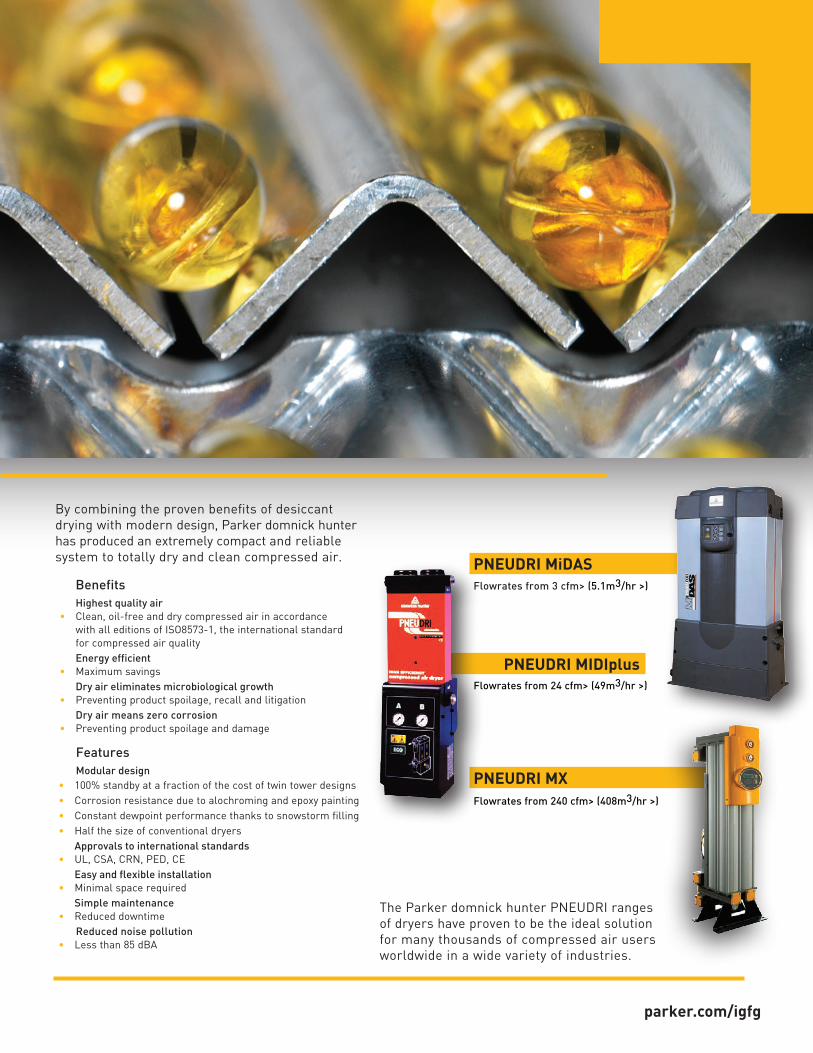
By combining the proven benefits of desiccant drying with modern design, Parker domnick hunter has produced an extremely compact and reliable system to totally dry and clean compressed air. PNEUDRI MiDAS
Flowrates from 3 cfm> (5.1m3/hr >)
PNEUDRI MIDIplus
PNEUDRI MX
Flowrates from 24 cfm> (49m3/hr >)
Flowrates from 240 cfm> (408m3/hr >)
BenefitsHighest quality air
• Clean, oil-free and dry compressed air in accordance with all editions of ISO8573-1, the international standard for compressed air qualityEnergy efficient
• Maximum savingsDry air eliminates microbiological growth
• Preventing product spoilage, recall and litigationDry air means zero corrosion
• Preventing product spoilage and damage
FeaturesModular design
• 100% standby at a fraction of the cost of twin tower designs• Corrosion resistance due to alochroming and epoxy painting• Constant dewpoint performance thanks to snowstorm filling• Half the size of conventional dryers
Approvals to international standards• UL, CSA, CRN, PED, CE
Easy and flexible installation• Minimal space required
Simple maintenance• Reduced downtime
Reduced noise pollution• Less than 85 dBA
The Parker domnick hunter PNEUDRI ranges of dryers have proven to be the ideal solution for many thousands of compressed air users worldwide in a wide variety of industries.
parker.com/igfg

PNEUDRI comprises of high tensile extruded aluminum columns each containing twin chambers filled with desiccant material which dries the compressed air as it passes through. One chamber is operational (drying), while the opposite chamber is regenerating using the Pressure Swing Desiccant (PSA) (heatless) method of drying.
A small volume of the dried compressed air is used to regenerate the saturated desiccant bed by expanding air from line pressure to atmospheric pressure, removing the water vapor adsorbed by the desiccant material, and therefore regenerating the dryer.
Modular design eliminates the need for complex valves and interconnecting piping which are used in conventional twin tower designs.
PNEUDRI - How it WorksWith the proven benefit of advanced aluminum forming technology, Parker domnick hunter has developed a twin tower desiccant dryer that is typically 60% of the size and weight of conventional designs.
These advanced desiccant dryers include ranges of heatless and PNEUDRI dryers which provide one of the most simple and cost-effective compressed air drying solutions.
Engineers at Parker domnick hunter have developed PNEUDRI using innovative aluminum forming technology, resulting in units that are typically 60% of the size and weight of conventional welded steel desiccant air dryers. Using a single, high tensile extruded aluminum column, the PNEUDRI modular design eliminates the need for complex valves or interconnecting piping.
Also, the length to diameter ratio of the internal voids and non-welded construction means that PNEUDRI does not require periodic inspections for insurance purposes, unlike traditional twin-tower air dryers that require out of service periods which can severely disrupt production schedules.
Dry Air Out
Wet Air In
Drying Columns
Upper DistributionManifold
Lower Distribution Manifold
Purge Air
Control Facia

Upper DistributionManifold
100% Stand-byCompared to traditional twin tower designs, 100% standby is available at a fraction of the cost as only one extra dryer bank is required.
Fits through a standard doorwayUnlike traditional twin tower designs, PNEUDRI dryers will fit through a standard doorway, eliminating the need for special access or facility structural dismantling during installation.
Unlike traditional twin tower dryer designs, PNEUDRI MAXI models can be multi-banked to provide extra compressed air drying capacity should demand increase in the future. There is no need to replace the dryer with a larger unit, additional capacity can be covered by simply adding extra bank(s), a feature only available with PNEUDRI.
Greater flexibility with multi-banking
Flexibility during maintenanceMulti-banking allows individual dryer banks to be easily isolated for routine service work, while maintaining your clean, dry air supply.
Only a desiccant dryer can provide the highest levels of dry compressed air.
parker.com/igfg

OIL-X FiltrationDesiccant dryers are designed for the removal of water vapor and not liquid water, water aerosols, oil, particulates or micro-organisms. Only by using Parker domnick hunter OIL-X pre and after filtration can the removal of these contaminants be assured and air quality in accordance with all editions of ISO8573-1 be guaranteed.
Modular Aluminum DesignAluminum extrusions are used throughout for drying chambers and distribution manifolds. This design allows the desiccant material to be retained within the drying chambers.'Snowstorm' filling, prevents movement of the desiccant material during operation and also eliminates desiccant attrition and breakdown which could lead to a loss of pressure dewpoint.
Adsorbent Desiccant MaterialSpecially selected desiccant materials provide:• Optimum desiccant and regeneration capacity -
to ensure consistent dewpoint• Low dusting - to prevent blockage of downstream filtration• High crush strength - to prevent breakdown
of the desiccant during operation• High resistance to aggressive and oil-free condensate -
for compatibility with all types of air compressor, their lubricants and condensate
'Snowstorm' Filling MethodUnique to Parker domnick hunter modular dryers is the snowstorm filling technique used to charge the drying chambers with adsorbent desiccant material. The benefits are:
• Achieves maximum packing density for the desiccant material, fully utilizing all of the available space envelope
• Prevents air channelling through the desiccant as experienced with twin tower designs. Due to channelling, twin tower designs require more desiccant to achieve an identical dewpoint, increasing physical size, operational and maintenance costs.
• Prevents desiccant attrition which can lead to dusting, blocked filters and loss of dewpoint
• Allows 100% of the available desiccant material to be used for drying, therefore reducing the amount of desiccant required and maintenance costs
• 100% of the desiccant is regenerated ensuring consistent dewpoint
• Provides a low, equal resistance to air flow allowing multiple drying chambers and multiple dryer banks to be used, a feature only available with PNEUDRI
Snowstorm Filled Bed
Consistent drying with no desiccant attrition
Loose Filled Bed
Inconsistent drying and desiccant attrition
1
2
3
4PNEUDRI - Four Key Features Guarantee Air Quality
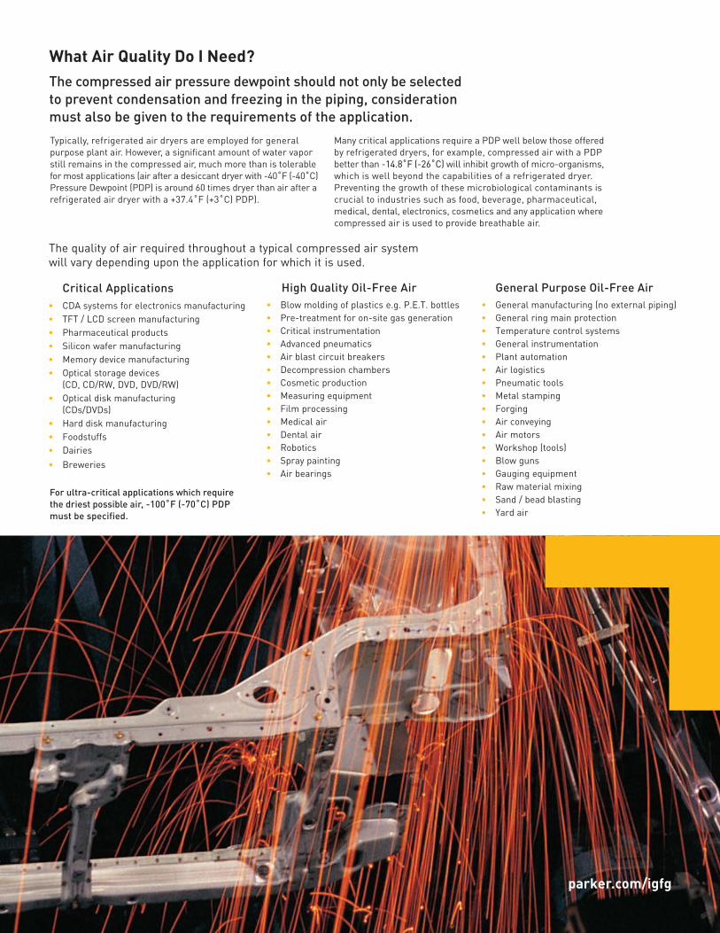
What Air Quality Do I Need?The compressed air pressure dewpoint should not only be selected to prevent condensation and freezing in the piping, consideration must also be given to the requirements of the application.Typically, refrigerated air dryers are employed for general purpose plant air. However, a significant amount of water vapor still remains in the compressed air, much more than is tolerable for most applications (air after a desiccant dryer with -40˚F (-40˚C) Pressure Dewpoint (PDP) is around 60 times dryer than air after a refrigerated air dryer with a +37.4˚F (+3˚C) PDP).
Many critical applications require a PDP well below those offered by refrigerated dryers, for example, compressed air with a PDP better than -14.8˚F (-26˚C) will inhibit growth of micro-organisms, which is well beyond the capabilities of a refrigerated dryer. Preventing the growth of these microbiological contaminants is crucial to industries such as food, beverage, pharmaceutical, medical, dental, electronics, cosmetics and any application where compressed air is used to provide breathable air.
The quality of air required throughout a typical compressed air system will vary depending upon the application for which it is used.
Critical Applications• CDA systems for electronics manufacturing• TFT / LCD screen manufacturing• Pharmaceutical products• Silicon wafer manufacturing• Memory device manufacturing• Optical storage devices
(CD, CD/RW, DVD, DVD/RW)• Optical disk manufacturing
(CDs/DVDs)• Hard disk manufacturing• Foodstuffs• Dairies• Breweries
High Quality Oil-Free Air• Blow molding of plastics e.g. P.E.T. bottles• Pre-treatment for on-site gas generation• Critical instrumentation• Advanced pneumatics• Air blast circuit breakers• Decompression chambers• Cosmetic production• Measuring equipment• Film processing• Medical air• Dental air• Robotics• Spray painting• Air bearings
General Purpose Oil-Free Air• General manufacturing (no external piping)• General ring main protection• Temperature control systems • General instrumentation• Plant automation • Air logistics• Pneumatic tools• Metal stamping• Forging• Air conveying• Air motors • Workshop (tools)• Blow guns• Gauging equipment• Raw material mixing• Sand / bead blasting• Yard air
parker.com/igfg
For ultra-critical applications which require the driest possible air, -100˚F (-70˚C) PDP must be specified.

Selecting the Right Dryer for Your Compressed Air SystemTo achieve the degree of air quality specified by ISO8573 - 1:2010, a careful approach to system design, commissioning and operation must be adopted. Purification equipment should be installed where the air is at the lowest possible temperature (i.e. downstream of after-coolers and air receivers). Point-of-use purification equipment should be installed as close as possible to the application.
Parker domnick hunter recommends that compressed air is treated:
• Prior to entry into the distribution system• At critical usage points and applications
This ensures that contamination already in the distribution system is removed.
1 Air Compressor
2 Wet Air Receiver
3 Condensate Drain
4 Water Separator
5 Coalescing Filters
6 Modular Desiccant Dryer
7 Dust Filter
8 Condensate Drainage
9 Oil / Water Separator
10 Dry Air Receiver
11 Oil Vapor Removal
12 Sterile Air Filter
13 On-site Nitrogen Gas Generator
14 Point of use Desiccant Dryer
15 Breathing Air Purifier
Key
General Purpose
Oil-Free Air Clean, Dry, Sterile Air for CriticalApplications
Clean, DryNitrogen
Clean, DryCompressed Air
Breathable Airwith CO/CO2
Reduction
Oil Vapor Removal
1
2
3
4
56
7
8
9
10
15
1213
14
11

0
FLOW cfm (m3/hr)
PNEUDRI MiDAS
PNEUDRI MIDIplus
PNEUDRI MX
294 (500) 589 (1000) 883 (1500) 1177 (2000) 1471 (2500)
THESE MODELS CAN BE MULTI-BANKED
1. Select the correction factor for maximum inlet temperature from the CFT table Correction Factor for 100°F (38°C) (round up to 104°F (40°C) = 1.04
2. Select the correction factor for minimum operating pressure from the CFP table Correction Factor for 116 psi g (8 bar g) (round down to 8 bar g) = 0.89
3. Select the correction factor for the required dewpoint from the CFD table Correction Factor for -40°F (-40°C PDP) = 1.00
4. Calculate the minimum drying capacity Minimum drying capacity = Compressed air flow rate x CFT x CFP x CFD Minimum drying capacity = 883 cfm (1500 m³/hr) x 1.04 x 0.89 x 1.00 = 817 cfm (1388 m³/hr) Model selected = MX106
5. Which controller is required? SMART controller is required therefore model selected = MXS106
6. Is DDS Energy Management System required? DDS Energy Management system is required therefore model selected = MXS106DS
Temperature Correction Factor CFT
Maximum Inlet Temperature
°F 104
°C 40
CFT 1.04
Pressure Correction Factor CFP
Minimum Inlet Pressure
psi g 116
bar g 8
CFP 0.89
Dewpoint Correction Factor CFD
Required Dewpoint
PDP °F -40PDP °C -40
CFD 1.00
If the minimum drying capacity exceeds the maximum values of the models shown within the tables, please contact Parker domnick hunter for advice regarding larger multi-banked dryers.
Which Dryer Do I Require?
To correctly select a dryer model, the flow rate of the dryer must be adjusted for the minimum operating pressure and maximum operational temperature of the system. If the dewpoint required is different to the standard dewpoint of the dryer then the flow rate must also be adjusted for the required outlet dewpoint.
Selection ExampleSelecting a dryer for a compressor producing at full load 883 cfm (1500 m³/hr) at 120 psi g (8.3 bar g) with 100°F (38°C) air inlet temperature and a pressure dewpoint of -40°F (-40°C).
parker.com/igfg
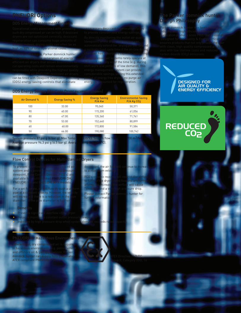
The Parker domnick hunter Design PhilosophyParker domnick hunter has been supplying industry with high efficiency filtration and purification products since 1963. Our philosophy ‘Designed for Air Quality & Energy Efficiency’ ensures products that not only provide the user with clean, high quality compressed air, but also with low lifetime costs and reduced carbon dioxide (CO2) emissions.
Air Demand % Energy Saving % Energy SavingP/A Kw
Environmental Saving P/A Kg CO2
100 33.00 95,040 50,371
90 40.00 115,200 61,056
80 47.00 135,360 71,741
70 53.00 152,640 80,899
60 60.00 172,800 91,584
50 66.00 190,080 100,742
System pressure 87 psi g (6 bar g). Max Temp 95°F (35°C). System flow 1000 cfm (1700 m3/hr). Average pressure 94.3 psi g (6.5 bar g). Average Temp 86°F (30°C).
DDS Energy Saving (Heatless Dryer example shown)
PNEUDRI OptionsDDS Energy Management SystemsOperational costs associated with providing such dry compressed air can be high. If desiccant dryers are not optimized correctly, desiccant regeneration can consume huge amounts of energy; indeed, drying costs can often be as high as 80% of total operational costs.
To address this issue, Parker domnick hunter has developed a new generation of energy efficient air dryers that allows businesses to cut operating costs and remain environmentally responsible while providing the highest quality compressed air. PNEUDRI desiccant air dryers can be fitted with Dewpoint Dependent Switching (DDS) energy saving controls that eliminate
unnecessary desiccant regeneration cycles to provide considerable energy savings.
By directly monitoring the outlet air quality (dewpoint) of the dryer, the system can automatically extend the “drying period” beyond a normally fixed cycle time if the on-line drying chamber has adsorptive capacity remaining.As compressed air systems rarely operate at full rated capacity all of the time (e.g. during shift work and periods of low demand), this energy management system can provide considerable savings. During this extended period of energy free drying, no purge air energy is consumed for regeneration.
PNEUDRI for Hazardous EnvironmentsWhere clean, dry compressed air is required in hazardous environments, e.g. petrochemical and offshore oil & gas applications, Parker domnick hunter can supply fully pneumatic ATEX compliant PNEUDRI dryers.
ATEX Directive 94/9/EC Group II, Category 2GD, T6
Flow Control Devices for Multi-Banked Dryers
To prevent overflowing your compressed air system and to assist in maintaining pressure dewpoint, Flow Control Devices (FCD’s) are available for multi-banked PNEUDRI DH, PNEUDRI MX and PNEUDRI MPX models.
For a set flowrate, air will flow through a uniform pipe at a constant velocity. However, the velocity will increase if there is a reduction in the pipe diameter. If the pipe diameter is further
decreased, the air flow will continue to increase to a maximum velocity.
FCD’s or sonic nozzles will restrict the airflow to 125% of the dryers rated flow and any further attempt to increase the airflow will cause “choking” and a very high pressure drop.
Please contact Parker domnick hunter for further information.
Benefits• Prevents significant overflow of the dryer.• Helps to maintain a constant outlet pressure dewpoint.• Indicates by high pressure drop when system demand exceeds rated capacity.

Model Pipe SizeInlet Flowrates
cfm L/S m3/min m3/hr
DAS1 3/8 " 3 1 0.09 5.1
DAS2 3/8 " 5 2 0.14 8.5
DAS3 3/8 " 8 4 0.23 13.6
DAS4 3/8 " 10 5 0.28 17.0
DAS5 3/8 " 13 6 0.37 22.1
DAS6 3/8 " 15 7 0.43 25.5
DAS7 3/8 " 20 9 0.57 34.0
• Stated flows are for operation at 100 psi g (7 bar g) with reference to 68°F (20°C), 1 bar a, 0% relative water vapor pressure. For flows at other pressures, apply the correction factors shown.
Dryer Performance
Model*Dewpoint (Standard) ISO8573-1:2010
Classification (standard)
*Dewpoint (Option 1) ISO8573-1:2010 Classification
(Option 1)ºF ºC ºF ºC
DAS -40 -40 Class 2 -100 -70 Class 1
Technical Data
Model
Min Operating Pressure
Max Operating Pressure
Min Inlet Temperature
Max Inlet Temperature
Max Ambient Temperature
psi g bar g psi g bar g °F °C °F °C °F °C
DAS 58 4 175 12 35 2 122 50 131 55
ModelElectrical Supply
(Standard) Tolerance ± 10%
Electrical Supply (Optional)
Tolerance ± 10%Thread Connection
Noise Level (average)
dB(A)
DAS 115 V/ 1ph / 60Hz 230 V/ 1ph / 50Hz NPT or BSPP <75
Electronic Controller
Options
Function
Power On Indication
Service Interval Indication
DAS • •
• For fully pneumatic applications, a PNEUDRI MINI range is available. Please contact Parker domnick hunter for further information.
Correction FactorsTemperature Correction Factor CFT
Maximum Inlet Temperature
°F 77 86 95 104 113 122
°C 25 30 35 40 45 50
CFT 1.00 1.00 1.00 1.04 1.14 1.37
Pressure Correction Factor CFP
Minimum Inlet Pressure
psi g 58 73 87 102 116 131 145 160 174
bar g 4 5 6 7 8 9 10 11 12
CFP 1.60 1.33 1.14 1.00 1.03 0.93 0.85 0.78 0.71
Dewpoint Correction Factor CFD Standard Option 1
Required Dewpoint
PDP °F -40 -100
PDP °C -40 -70
CFD 1.00 1.43
Model Filter Pipe Size NPT
Inlet General Purpose Pre-filter
Inlet High Efficiency Filter
Outlet Dust Filter
DAS1 3/8" AOP0010BNFI Included Included
DAS2 3/8" AOP0010BNFI Included Included
DAS3 3/8" AOP0010BNFI Included Included
DAS4 3/8" AOP0010BNFI Included Included
DAS5 3/8" AOP0010BNFI Included Included
DAS6 3/8" AOP0010BNFI Included Included
DAS7 3/8" AOP0010BNFI Included Included
Weights and Dimensions
Model Pipe Size
DimensionsWeight
Height (H) Width (W) Depth (D)
ins mm ins mm ins mm lbs Kg
DAS1 3/8 " 16.6 422 11.4 289 5.9 149 24.2 11
DAS2 3/8 " 19.7 500 11.4 289 5.9 149 28.7 13
DAS3 3/8 " 24.2 616 11.4 289 5.9 149 35.3 16
DAS4 3/8 " 27.2 692 11.4 289 5.9 149 39.7 18
DAS5 3/8 " 33.3 847 11.4 289 5.9 149 44.1 20
DAS6 3/8 " 35.7 906 11.4 289 5.9 149 50.7 23
DAS7 3/8 " 43.2 1098 11.4 289 5.9 149 61.7 28
Recommended Filtration
Product Selection
PNEUDRI MiDAS
H
DAS1-7
W D
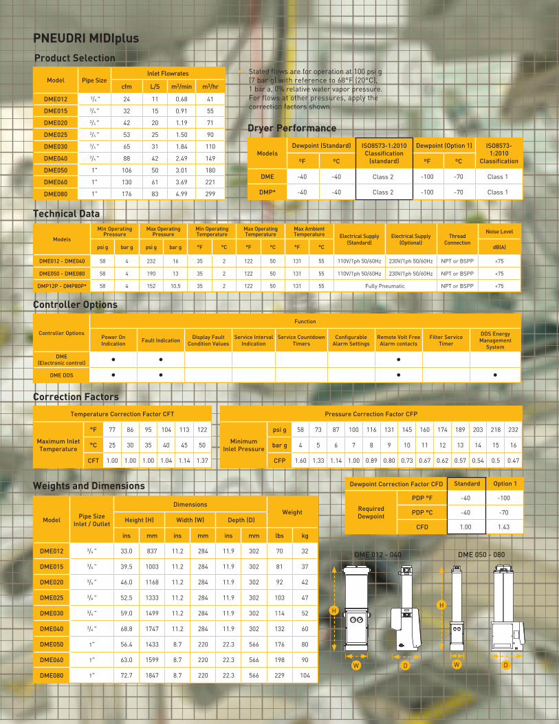
PNEUDRI MIDIplus
• Stated flows are for operation at 100 psi g (7 bar g) with reference to 68°F (20°C), 1 bar a, 0% relative water vapor pressure. For flows at other pressures, apply the correction factors shown.
Product Selection
Model Pipe SizeInlet Flowrates
cfm L/S m3/min m3/hr
DME012 3/4 " 24 11 0.68 41
DME015 3/4 " 32 15 0.91 55
DME020 3/4 " 42 20 1.19 71
DME025 3/4 " 53 25 1.50 90
DME030 3/4 " 65 31 1.84 110
DME040 3/4 " 88 42 2.49 149
DME050 1" 106 50 3.01 180
DME060 1" 130 61 3.69 221
DME080 1" 176 83 4.99 299
Dryer Performance
ModelsDewpoint (Standard) ISO8573-1:2010
Classification (standard)
Dewpoint (Option 1) ISO8573-1:2010
Classification ºF ºC ºF ºC
DME -40 -40 Class 2 -100 -70 Class 1
DMP* -40 -40 Class 2 -100 -70 Class 1
Technical Data
Models
Min Operating Pressure
Max Operating Pressure
Min Operating Temperature
Max Operating Temperature
Max Ambient Temperature Electrical Supply
(Standard)Electrical Supply
(Optional)Thread
Connection
Noise Level
psi g bar g psi g bar g °F °C °F °C °F °C dB(A)
DME012 - DME040 58 4 232 16 35 2 122 50 131 55 110V/1ph 50/60Hz 230V/1ph 50/60Hz NPT or BSPP <75
DME050 - DME080 58 4 190 13 35 2 122 50 131 55 110V/1ph 50/60Hz 230V/1ph 50/60Hz NPT or BSPP <75
DMP12P - DMP80P* 58 4 152 10.5 35 2 122 50 131 55 Fully Pneumatic NPT or BSPP <75
Controller Options
Function
Power On Indication Fault Indication Display Fault
Condition ValuesService Interval
IndicationService Countdown
TimersConfigurable
Alarm SettingsRemote Volt Free
Alarm contactsFilter Service
Timer
DDS Energy Management
System
DME (Electronic control) • • •
DME DDS • • • •
Controller Options
Temperature Correction Factor CFT
Maximum Inlet Temperature
°F 77 86 95 104 113 122
°C 25 30 35 40 45 50
CFT 1.00 1.00 1.00 1.04 1.14 1.37
Pressure Correction Factor CFP
Minimum Inlet Pressure
psi g 58 73 87 100 116 131 145 160 174 189 203 218 232
bar g 4 5 6 7 8 9 10 11 12 13 14 15 16
CFP 1.60 1.33 1.14 1.00 0.89 0.80 0.73 0.67 0.62 0.57 0.54 0.5 0.47
Correction Factors
Dewpoint Correction Factor CFD Standard Option 1
Required Dewpoint
PDP °F -40 -100
PDP °C -40 -70
CFD 1.00 1.43Model Pipe Size
Inlet / Outlet
DimensionsWeight
Height (H) Width (W) Depth (D)
ins mm ins mm ins mm lbs kg
DME012 3/4 " 33.0 837 11.2 284 11.9 302 70 32
DME015 3/4 " 39.5 1003 11.2 284 11.9 302 81 37
DME020 3/4 " 46.0 1168 11.2 284 11.9 302 92 42
DME025 3/4 " 52.5 1333 11.2 284 11.9 302 103 47
DME030 3/4 " 59.0 1499 11.2 284 11.9 302 114 52
DME040 3/4 " 68.8 1747 11.2 284 11.9 302 132 60
DME050 1" 56.4 1433 8.7 220 22.3 566 176 80
DME060 1" 63.0 1599 8.7 220 22.3 566 198 90
DME080 1" 72.7 1847 8.7 220 22.3 566 229 104
Weights and Dimensions
DME 012 - 040 DME 050 - 080
H
W D
H
W D
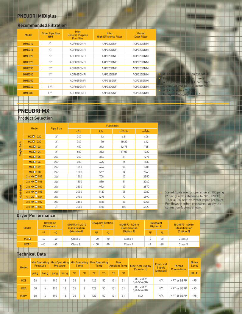
• ATEX compliant option available.• For hazardous environments,
a fully pneumatic ATEX compliant version of PNEUDRI is available.
• ATEX Directive 94/9/EC Group II, Category 2GD, T6.
Model Filter Pipe Size NPT
Inlet General Purpose
Pre-filter
Inlet High Efficiency Filter
Outlet Dust Filter
DME012 3/4" AOP020DNFI AAP020DNFI AOP020DNMI
DME015 3/4" AOP020DNFI AAP020DNFI AOP020DNMI
DME020 3/4" AOP020DNFI AAP020DNFI AOP020DNMI
DME025 3/4" AOP020DNFI AAP020DNFI AOP020DNMI
DME030 3/4" AOP020DNFI AAP020DNFI AOP020DNMI
DME040 3/4" AOP025DNFI AAP025DNFI AOP025DNMI
DME050 1" AOP025ENFI AAP025ENFI AOP025ENMI
DME060 1 1/2" AOP030GNFI AAP030GNFI AOP030GNMI
DME080 1 1/2” AOP030GNFI AAP030GNFI AOP030GNMI
Recommended Filtration
PNEUDRI MIDIplusSi
ngle
Ban
k
Model Pipe SizeFlowrates
cfm L/s m3/min m3/hr
MX 102C 2" 240 113 6.81 408
MX 103C 2" 360 170 10.22 612
MX 103 2" 450 213 12.78 765
MX 104 2" 600 283 17.03 1020
MX 105 21/2" 750 354 21 1275
MX 106 21/2" 900 425 26 1530
MX 107 21/2" 1050 496 30 1785
MX 108 21/2" 1200 567 34 2040
• Stated flows are for operation at 100 psi g (7 bar g) with reference to 68°F (20°C), 1 bar a, 0% relative water vapor pressure.For flows at other pressures, apply the correction factors shown.
PNEUDRI MXProduct Selection
Dryer Performance
Model
Dewpoint (Standard) ISO8573-1:2010
Classification (standard)
Dewpoint (Option 1) ISO8573-1:2010
Classification (Option 1)
Dewpoint (Option 2) ISO8573-1:2010
Classification (Option 2)ºF ºC ºF ºC ºF ºC
MX -40 -40 Class 2 -100 -70 Class 1 -4 -20 Class 3
MXP* -40 -40 Class 2 -100 -70 Class 1 -4 -20 Class 3
Technical Data
Model
Min Operating Pressure
Max Operating Pressure
Min Operating Temp
Max Operating Temp
Max Ambient Temp Electrical Supply
(Standard)
Electrical Supply
(Optional)
Thread Connections
Noise Level
psi g bar g psi g bar g °F °C °F °C °F °C dB (A)
MXS 58 4 190 13 35 2 122 50 131 51 85 - 265 V 1ph 50/60Hz N/A NPT or BSPP <75
MXA 58 4 190 13 35 2 122 50 131 51 85 - 265 V 1ph 50/60Hz N/A NPT or BSPP <75
MXP* 58 4 190 13 35 2 122 50 131 51 N/A N/A NPT or BSPP <75
Mul
ti-B
ank
2 x MX 105 21/2" 1500 708 43 2550
2 x MX 106 21/2" 1800 850 51 3060
2 x MX 107 21/2" 2100 992 60 3570
2 x MX 108 21/2" 2400 1133 68 4080
3 x MX 106 21/2" 2700 1275 77 4590
3 x MX 107 21/2" 3150 1488 89 5355
3 x MX 108 21/2" 3600 1700 102 6120

Controller Options
Controller Option
Function
Power on Indication
Fault Indication
Display Fault Condition
Values
Service Interval
Indication
Service Countdown
Timers
Configurable Alarm
Settings
Remote Volt Free Alarm
Contacts
Filter Service Timer
DDS Energy Management
System
SMART • • • •SMART DDS • • • • •ADVANCED • • • • • • • • •
Correction Factors
Temperature Correction Factor CFT
Maximum Inlet Temperature
°F 77 86 95 104 113 122
°C 25 30 35 40 45 50
CFT 1.00 1.00 1.00 1.04 1.14 1.37
Pressure Correction Factor CFP
Minimum Inlet Pressure
psi g 4 5 6 7 8 9 10 11 12 13
bar g 58 73 87 100 116 131 145 160 174 189
CFP 1.60 1.33 1.14 1.00 0.89 0.80 0.73 0.67 0.62 0.57
Dewpoint Correction Factor CFD Standard Option 1 Option 2
Required Dewpoint
PDP °F -40 -100 -20
PDP °C -40 -70 -4
CFD 1.00 1.43 0.91
Weights and Dimensions
ModelPipe Size
Inlet / Outlet
DimensionsWeight
Height (H) Width (W) Depth (D)
ins mm ins mm ins mm lbs kg
MX 102C 2" 64.8 1647 27.0 687 21.7 550 518 235
MX 103C 2" 64.8 1647 33.7 856 21.7 550 696 316
MX 103 2" 74.5 1892 33.7 856 21.7 550 782 355
MX 104 2" 74.5 1892 40.3 1025 21.7 550 992 450
MX 105 21/2" 74.5 1892 47.0 1194 21.7 550 1197 543
MX 106 21/2" 74.5 1892 53.6 1363 21.7 550 1404 637
MX 107 21/2" 74.5 1892 60.3 1532 21.7 550 1611 731
MX 108 21/2" 74.5 1892 67.0 1701 21.7 550 1818 825
MX 110 - 112
Model Filter Pipe Size NPT
Inlet General Purpose
Pre-filter
Inlet High Efficiency Filter
Outlet Dust Filter
MX 102C 2" AOP040HNFI AAP040HNFI AOP040HNFI
MX 103C 2" AOP040HNFI AAP040HNFI AOP040HNFI
MX 103 2" AOP040HNFI AAP040HNFI AOP040HNFI
MX 104 2 1/2" AOP045INFI AAP045INFI AOP045INFI
MX 105 2 1/2” AOP050INFI AAP050INFI AOP050INFI
MX 106 2 1/2” AOP050INFI AAP050INFI AOP050INFI
MX 107 2 1/2” AOP055INFI AAP055INFI AOP055INFI
MX 108 2 1/2” AOP055INFI AAP055INFI AOP055INFI
Recommended Filtration
Dryer Model Controller Model Number of Drying Banks
Number of Drying Columns
MX S = SmartA = Advanced
No of individual dryers in installation
Number of columns per dryer bank
MX S 3 08
DS = DDS Fitted(DDS standard with
Advanced Controllers)
DS
DDS Energy Management
Dryer Coding Example
• ATEX compliant option available.• For hazardous environments, a
fully pneumatic ATEX compliant version of PNEUDRI is available.
• ATEX Directive 94/9/EC Group II, Category 2GD, T6.
WD
H
parker.com/igfg
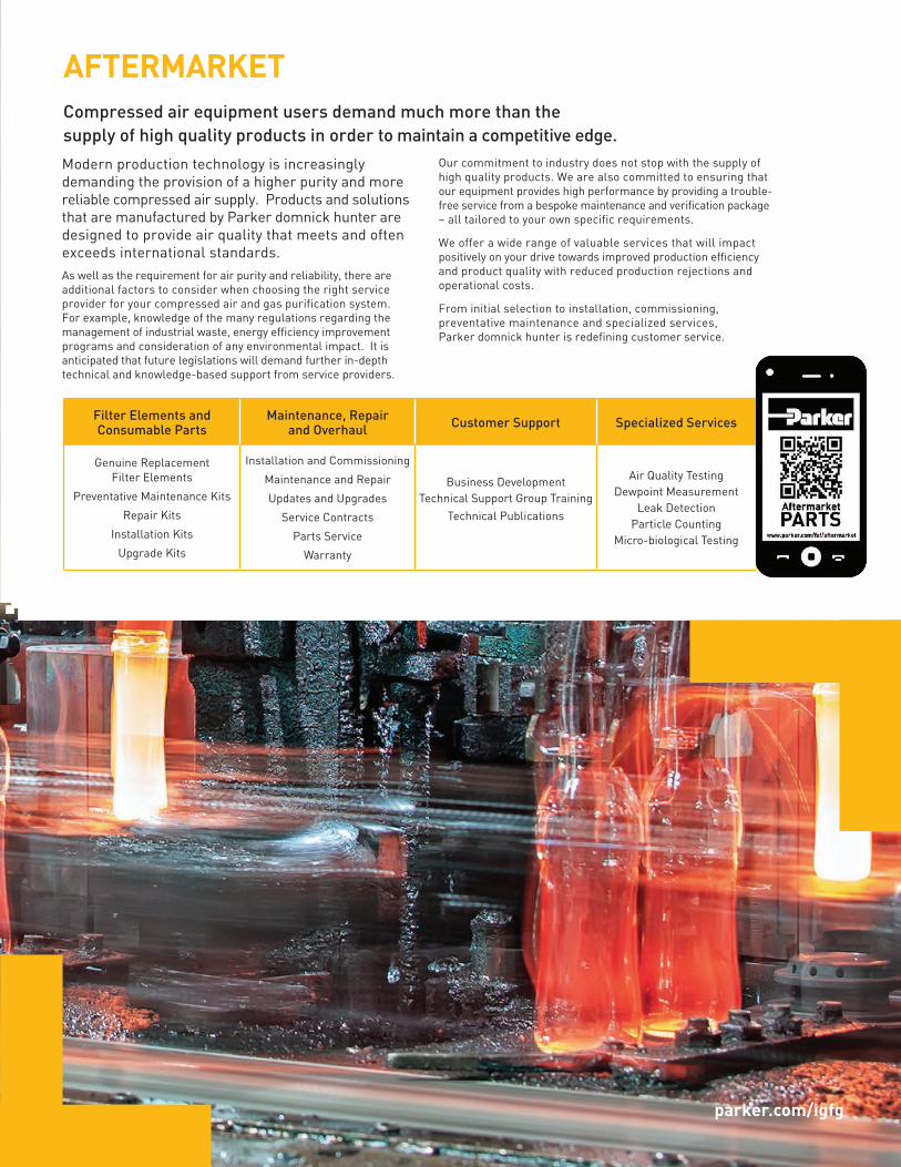
AFTERMARKETCompressed air equipment users demand much more than the supply of high quality products in order to maintain a competitive edge.
Filter Elements and Consumable Parts
Maintenance, Repair and Overhaul Customer Support Specialized Services
Genuine Replacement Filter Elements
Preventative Maintenance Kits
Repair Kits
Installation Kits
Upgrade Kits
Installation and Commissioning
Maintenance and Repair
Updates and Upgrades
Service Contracts
Parts Service
Warranty
Business DevelopmentTechnical Support Group Training
Technical Publications
Air Quality TestingDewpoint Measurement
Leak DetectionParticle Counting
Micro-biological Testing
Modern production technology is increasingly demanding the provision of a higher purity and more reliable compressed air supply. Products and solutions that are manufactured by Parker domnick hunter are designed to provide air quality that meets and often exceeds international standards. As well as the requirement for air purity and reliability, there are additional factors to consider when choosing the right service provider for your compressed air and gas purification system. For example, knowledge of the many regulations regarding the management of industrial waste, energy efficiency improvement programs and consideration of any environmental impact. It is anticipated that future legislations will demand further in-depth technical and knowledge-based support from service providers.
Our commitment to industry does not stop with the supply of high quality products. We are also committed to ensuring that our equipment provides high performance by providing a trouble-free service from a bespoke maintenance and verification package – all tailored to your own specific requirements.
We offer a wide range of valuable services that will impact positively on your drive towards improved production efficiency and product quality with reduced production rejections and operational costs.
From initial selection to installation, commissioning, preventative maintenance and specialized services, Parker domnick hunter is redefining customer service.
Parker Hannifin CorporationIndustrial Gas Filtrationand Generation Division4087 Walden AvenueLancaster, NY 14086phone 800 343 4048www.parker.com/igfg
© 2017 Parker Hannifin Corporation. Product names are trademarks or registered trademarks of their respective companies
Worldwide Filtration Manufacturing Locations
BRO_dH-PNEUDRI_102017
North America
Compressed Air Treatment
Industrial Gas Filtration and Generation DivisionLancaster, NY 716 686 6400 www.parker.com/igfg
Haverhill, MA 978 858 0505 www.parker.com/igfg
Engine Filtration
Racor Modesto, CA 209 521 7860 www.parker.com/racor
Holly Springs, MS 662 252 2656 www.parker.com/racor
Hydraulic Filtration
Hydraulic & Fuel FiltrationMetamora, OH 419 644 4311 www.parker.com/hydraulicfilter
Laval, QC Canada 450 629 9594 www.parkerfarr.com
VelconColorado Springs, CO 719 531 5855 www.velcon.com
Process Filtration
domnick hunter Process FiltrationSciLogOxnard, CA 805 604 3400 www.parker.com/processfiltration
Water Purification
Village Marine, Sea Recovery, Horizon Reverse OsmosisCarson, CA 310 637 3400 www.parker.com/watermakers
Europe
Compressed Air Treatment
domnick hunter Filtration & Separation Gateshead, England +44 (0) 191 402 9000 www.parker.com/dhfns
Parker Gas SeparationsEtten-Leur, Netherlands +31 76 508 5300 www.parker.com/dhfns
Hiross Airtek Essen, Germany +49 2054 9340 www.parker.com/hzfd
Padova, Italy +39 049 9712 111 www.parker.com/hzfd
Engine Filtration & Water Purification
Racor Dewsbury, England +44 (0) 1924 487 000 www.parker.com/rfde
Racor Research & DevelopmentStuttgart, Germany +49 (0)711 7071 290-10
Hydraulic Filtration
Hydraulic Filter Arnhem, Holland +31 26 3760376 www.parker.com/hfde
Urjala, Finland
+358 20 753 2500
Condition MonitoringParker KittiwakeWest Sussex, England +44 (0) 1903 731 470 www.kittiwake.com
Process Filtration
domnick hunter Process FiltrationParker Twin Filter BVBirtley, England +44 (0) 191 410 5121 www.parker.com/processfiltration
Asia Pacific
Australia Castle Hill, Australia +61 2 9634 7777 www.parker.com/australia
China Shanghai, China +86 21 5031 2525 www.parker.com/china
IndiaChennai, India +91 22 4391 0700 www.parker.com/india
Parker FowlerBangalore, India +91 80 2783 6794 www.johnfowlerindia.com
Japan Tokyo, Japan +81 45 870 1522 www.parker.com/japan
Korea Hwaseon-City +82 31 359 0852 www.parker.com/korea
SingaporeJurong Town, Singapore +65 6887 6300 www.parker.com/singapore
Thailand Bangkok, Thailand +66 2186 7000 www.parker.com/thailand
Latin AmericaParker Comercio Ltda. Filtration Division Sao Paulo, Brazil +55 12 4009 3500 www.parker.com/br
Pan American Division Miami, FL 305 470 8800 www.parker.com/panam
AfricaAeroport Kempton Park, South Africa +27 11 9610700 www.parker.com/africa