FMH Part 2 Quality assurance in Nuclear Medicine Imaging units
70
FMH Part 2 Quality assurance in Nuclear Medicine Imaging units Legal requirements… Silvano Gnesin PhD. Prof. Francis R. Verdun Institute of Radiation Physics 1007 Lausanne
Transcript of FMH Part 2 Quality assurance in Nuclear Medicine Imaging units
FMH Part 2
Quality assurance in Nuclear Medicine Imaging units
Legal requirements…
Silvano Gnesin PhD.
Prof. Francis R. Verdun
Institute of Radiation Physics
1007 Lausanne

Content
Quality assurance (QA)
- Legal requirements
- Why; who; when; how
ORaP – Art. 74.7 (intervention of a medical physicist)
Technical notices
CT
Dose indicators
DRL concept
2/54
Why QA
Identify deviation from normal :
- Device dependent / environment dependent
Guarantee stability of performance
Base for Image Quality (IQ) optimization
Legal requirement (FBPH)
3/53
Who performs QA
Usually the tecnologist (stability tests)
- Supervision by a medical physicist
Vendor technical support (Acceptance / Periodical maintenance)
- Supervision by a medical physicist
4/53

5/54
Principle
Three types of tests Acceptance test + reference measurements
Before 1st patient
Manufacturer (better if a medical physicists is available)
Stability test (Routinely) (User)
Maintenance + Status test + Update of reference Manufacturer (every 6 months)
Reference Values
6/54
When QA: Timing requirements
Stability tests (routinely)
Daily
Weekly
Every six months
Maintenance– Status test – Reference
Every six months

Medical physicist involvement Legal background
Orap – Art. 74.7 74.7 Pour les applications en médecine nucléaire et en radiologie
interventionnelle par radioscopie ainsi que pour la tomodensitométrie, le titulaire de l'autorisation doit faire appel périodiquement à un physicien médical selon l'al. 4.
Compliance with Euratom 97/43 Limitation
Justification
Optimization
Technical notices
Unit requirements
7/54

Medical physicist requirement
8/54
Medical physicist requirement
9/53
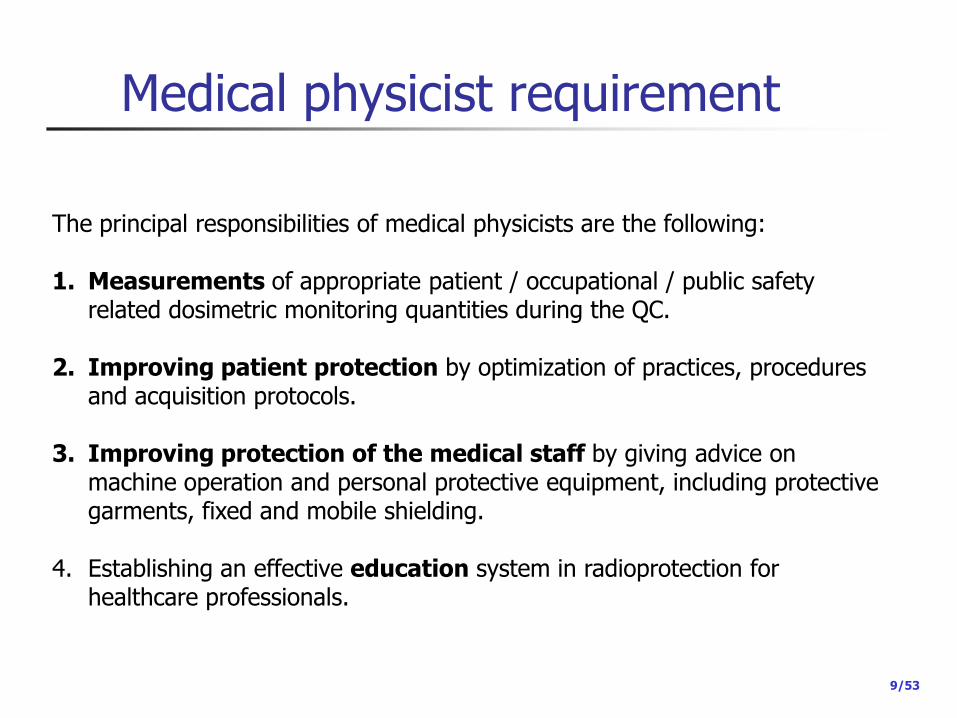
The principal responsibilities of medical physicists are the following: 1. Measurements of appropriate patient / occupational / public safety
related dosimetric monitoring quantities during the QC.
2. Improving patient protection by optimization of practices, procedures and acquisition protocols.
3. Improving protection of the medical staff by giving advice on machine operation and personal protective equipment, including protective garments, fixed and mobile shielding.
4. Establishing an effective education system in radioprotection for healthcare professionals.

Recommendation (FOPH)
10/54
Recommended hiring times of medical physicists (days/year)

Goals
Should not duplicate manufacturer’s tasks
But some basic measurements can be done
Check if:
The balance between patient dose and image quality is optimal
Optimize staff dose
Work in close collaboration with the staff
Continuous education
Radiation protection
Optimal use of the imaging unit
11/54

Requirements concerning units Nuclear Medicine
12/54
13/54
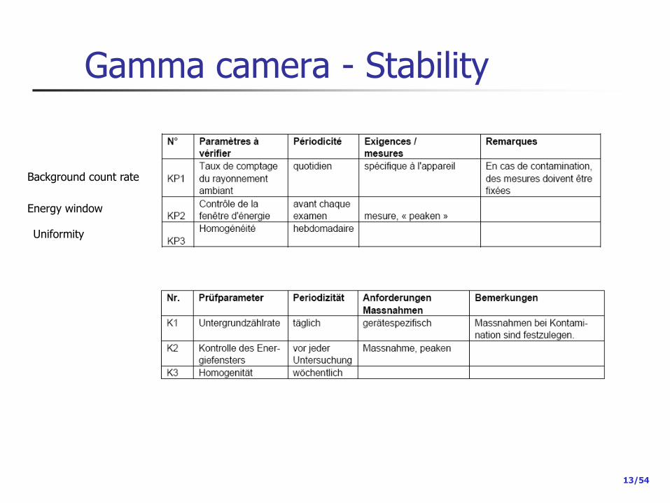
Gamma camera - Stability
Background count rate
Energy window
Uniformity
14/54
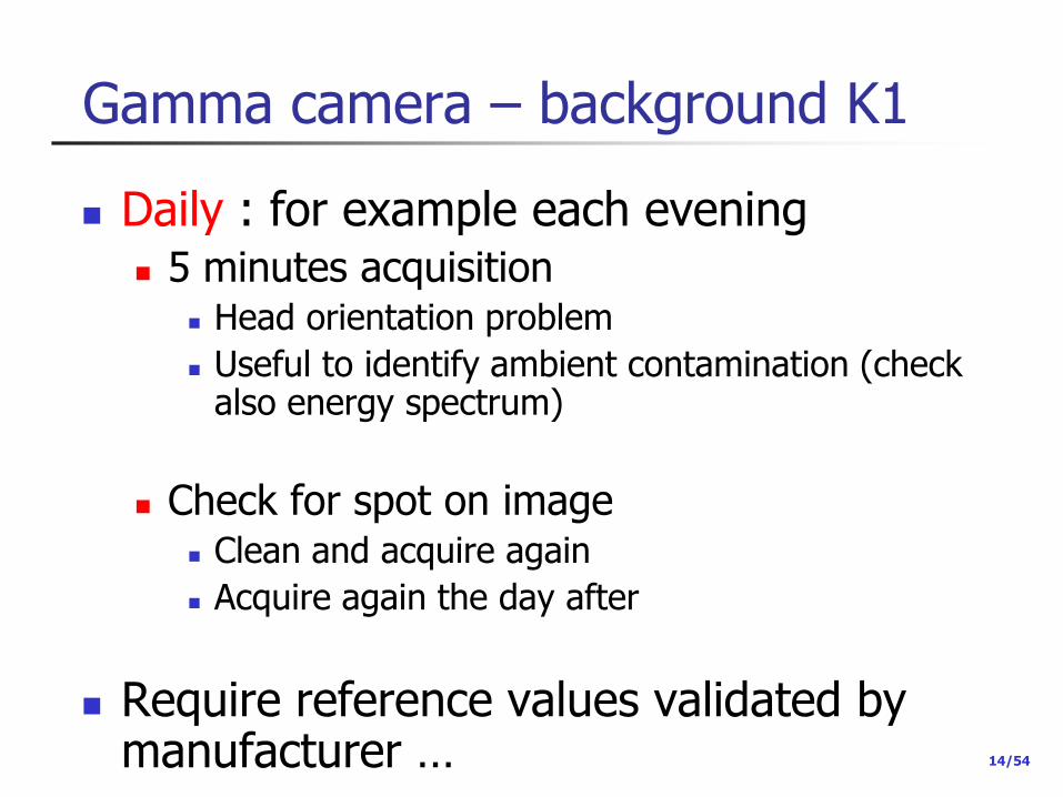
Gamma camera – background K1
Daily : for example each evening 5 minutes acquisition
Head orientation problem
Useful to identify ambient contamination (check also energy spectrum)
Check for spot on image Clean and acquire again
Acquire again the day after
Require reference values validated by manufacturer …

15/35
Gamma camera – Energy window K2 Before each acquisition
Why?
Mistuned Energy window Loss of counts
Sub-optimal scatter correction
Image quality problems possible (loss of uniformity)

16/54
Gamma camera – Stability (K3)
Homogeneity
The matrix size matter
Number of counts – matrix size
1Mio in 512x512
262144 pixels 3.8 counts/pixel
s = 1.9 50% uncertainty
1Mio in 64x64
4096 pixels 244 counts/pixel
s = 15.6 6% uncertainty
If restricted number of counts
Be careful on matrix size
At least 1000 counts/pixel
s = 31.6 3% uncertainty

17/54
Gamma camera - Stability
Assessment
Subjective
Narrow window
Objective (Integral and Differential Uniformity)
IU Global evaluation DU Local evaluation

18/54
Gamma camera - Stability
Example
19/35
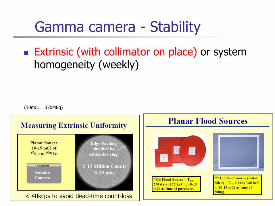
Gamma camera - Stability
Extrinsic (with collimator on place) or system homogeneity (weekly)
< 40kcps to avoid dead-time count-loss
(10mCi = 370MBq)
20/54
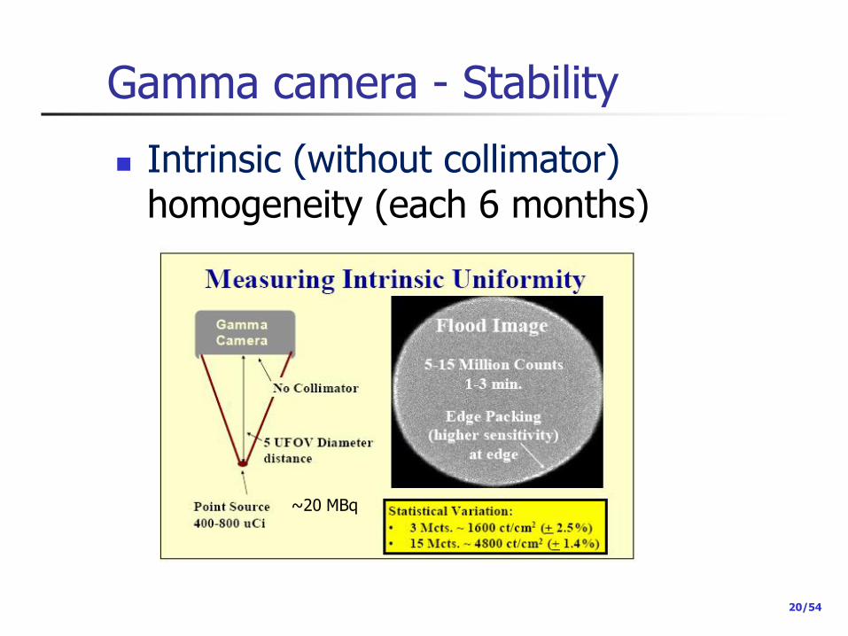
Gamma camera - Stability
Intrinsic (without collimator) homogeneity (each 6 months)
~20 MBq

21/54
Gamma camera - Stability
Be careful on the fact that:
22/54
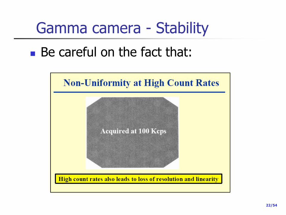
Gamma camera - Stability
Be careful on the fact that:
23/35
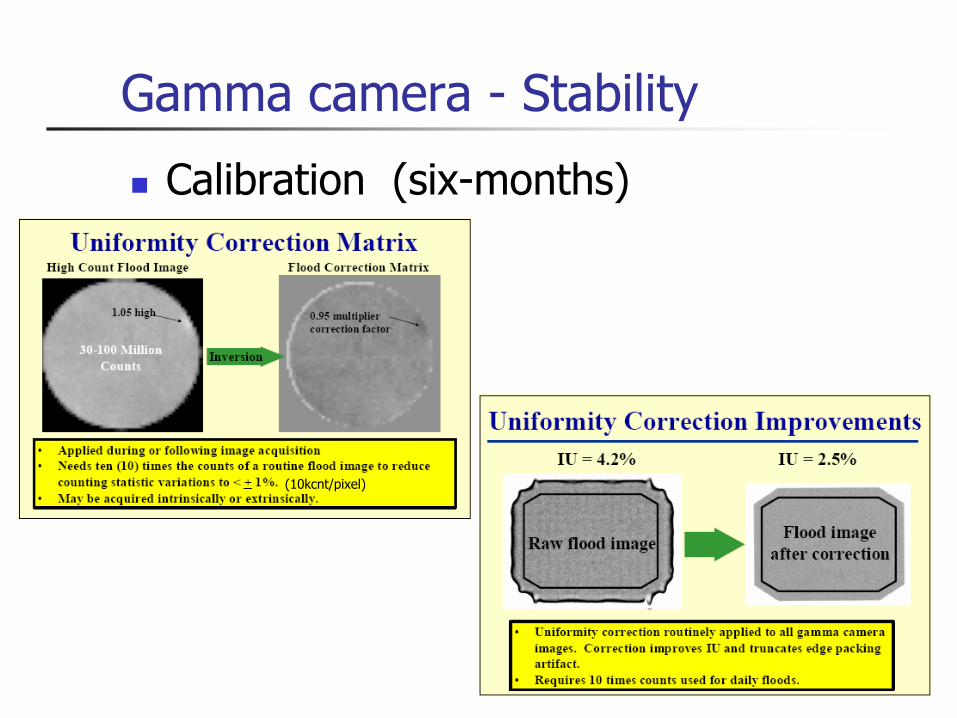
Gamma camera - Stability
Calibration (six-months)
(10kcnt/pixel)

24/54
Gamma camera - Stability

25/53
Gamma camera - Stability
Calibration
P. Zanconico, Routine Quality Control of Clinical Nuclear Medicine Instrumentation: A Brief Review J. Nucl. Med. 49 (2008)
Full calibration by applying all correction Vendor @ periodic maintenance (every 6 months)

26/54
Gamma camera - Stability Summary
Intrinsic (without collimator) calibration requires
Precise point source and scatter free condition
Beam as parallel as possible (5 FOV far point-like source)
Extrinsic (with collimator on place)
Planar flood source
Required for each collimator (LE, ME, HE)
Includes intrinsic calibration
At least weekly

27/54
Gamma camera – Stability reference levels and action levels
http://www.aapm.org/meetings/amos2/pdf/29-7895-49774-307.pdf
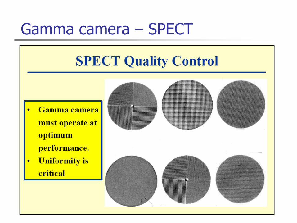
Gamma camera – SPECT
29/35
Gamma camera
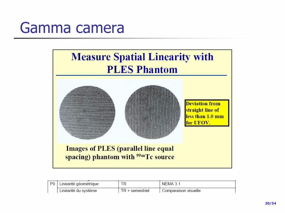
30/54
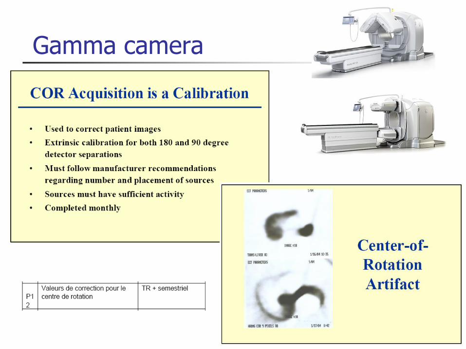
Gamma camera

31/54
Gamma camera
Visual assessment

32/54
Gamma camera – SPECT
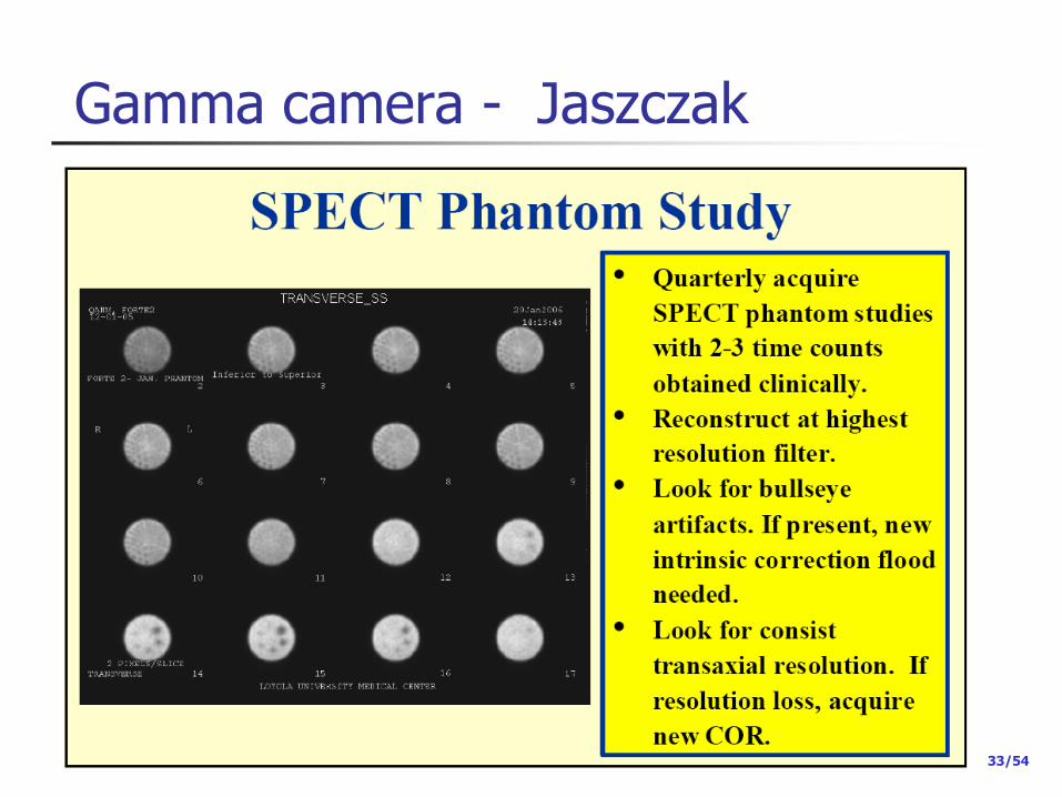
33/54
Gamma camera - Jaszczak
34/35
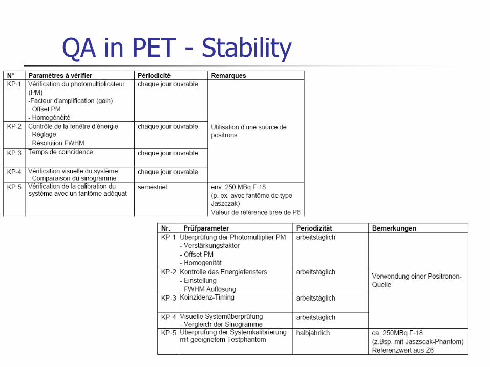
QA in PET - Stability

35/53
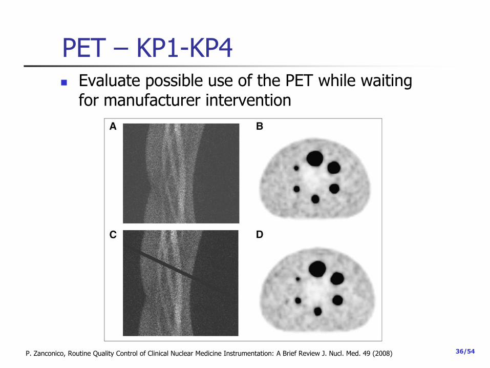
PET – KP1-KP4
Done automatically during calibration
Should be documented
Axial direction
Acceptable blank scan
One block out of tolerance
P. Zanconico, Routine Quality Control of Clinical Nuclear Medicine Instrumentation: A Brief Review J. Nucl. Med. 49 (2008)
36/54
PET – KP1-KP4 Evaluate possible use of the PET while waiting
for manufacturer intervention
P. Zanconico, Routine Quality Control of Clinical Nuclear Medicine Instrumentation: A Brief Review J. Nucl. Med. 49 (2008)

37/54
PET – Stability – KP 5
Image quality (each 6 month)
38/54
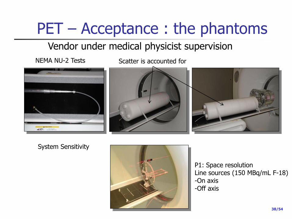
PET – Acceptance : the phantoms
P1: Space resolution Line sources (150 MBq/mL F-18) -On axis -Off axis
System Sensitivity
NEMA NU-2 Tests Scatter is accounted for
Vendor under medical physicist supervision

39/54
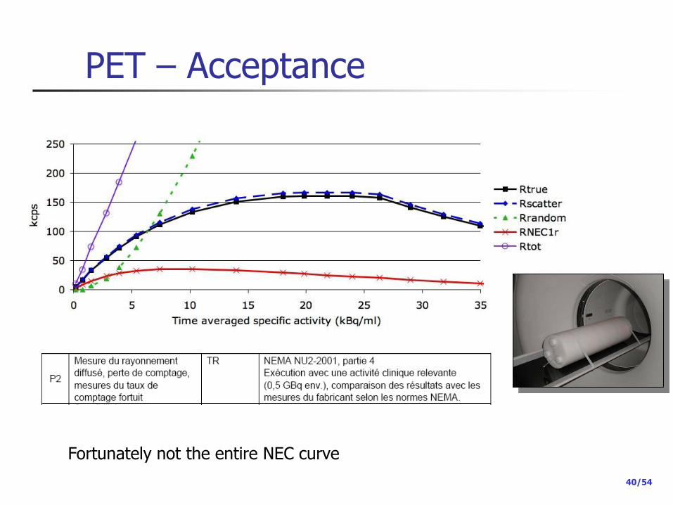
PET – Acceptance
40/54
PET – Acceptance
Fortunately not the entire NEC curve
41/54
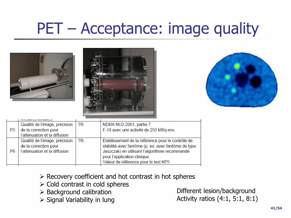
PET – Acceptance: image quality
Recovery coefficient and hot contrast in hot spheres Cold contrast in cold spheres Background calibration Signal Variability in lung
Different lesion/background Activity ratios (4:1, 5:1, 8:1)

42/54
PET - CT Legal CT requirements need to be satisfied also
Image fusion to be controlled
Attenuation correction to be controlled
CT in SPECT/CT and PET/CT are considered as stand-alone CT
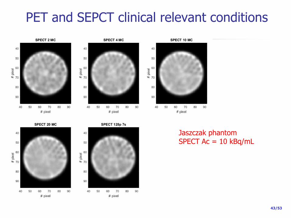
PET and SEPCT clinical relevant conditions
43/53
Jaszczak phantom SPECT Ac = 10 kBq/mL
44/53
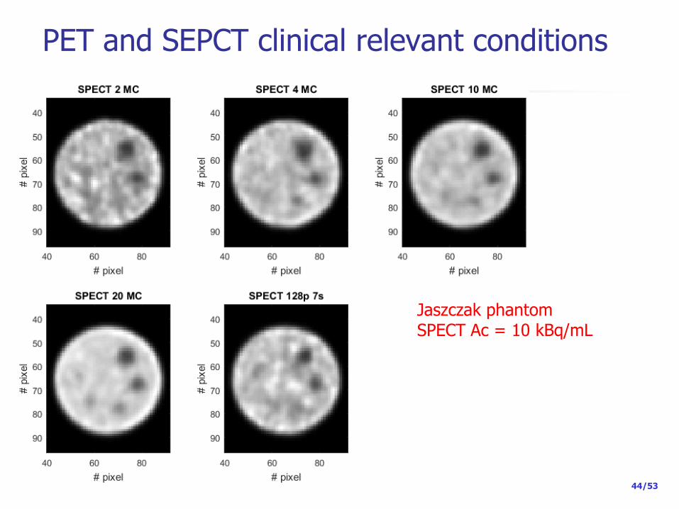
PET and SEPCT clinical relevant conditions
Jaszczak phantom SPECT Ac = 10 kBq/mL

45/53
PET and SEPCT clinical relevant conditions NEMA NU2 phantom SPECT Ac = 10 kBq/mL

46/53
PET and SEPCT clinical relevant conditions
SPECT
PET
PET
PET

47/53
PET and SEPCT clinical relevant conditions
Optimization of acquisition/reconstruction protocols… for both PET and SPECT according to clinical requirements Reduce dose to the patient ? in PET it seems to be possible -New technologies (iterative reconstruction with TOF + PSF) -Large detector rings -SiPM detector (coming now in the market)
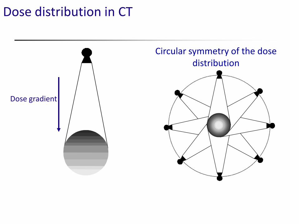
Dose distribution in CT
Circular symmetry of the dose distribution
Dose gradient

The CT dose Index (CTDI) dose units: Energy/mass = J/Kg = Gy (usually mGy)
Use pencil chamber to measure dose from single rotation including scatter tail
C. McCollough et Al, Radiology 2011; 259:311–316
D(z) = axial (z) dose profile
nT = nominal axial beam width
100 mm sensitive pencil length

Average dose and diameter
32 cm
16 cm
20
20
20 20 10
40
40
40 40 40

CTDIw
Weighted CTDI (CTDIw)
Dose indicator in PMMA cylinders
Ø 16 cm : Adult (head neck) – Pediatric
Ø 32 cm : Adult (body)
CTDIw = 1/3 CTDIcenter + 2/3 CTDIperiphery
Same scan parameters CTDIw,16 cm ~ 2 x CTDIw,32cm
nCTDIw = CTDIw /mAs in a 360 tube rotation

CTDIw - CTDIvol
Sequential acquisition
CTDIw = nCTDIw x mAs
mAs for one 360° tube rotation
Helical acquisition
CTDIvol = CTDIw / pitch
Pitch :
Table displacement in1 tube rotation(mm)
X-ray beam collimation (mm)
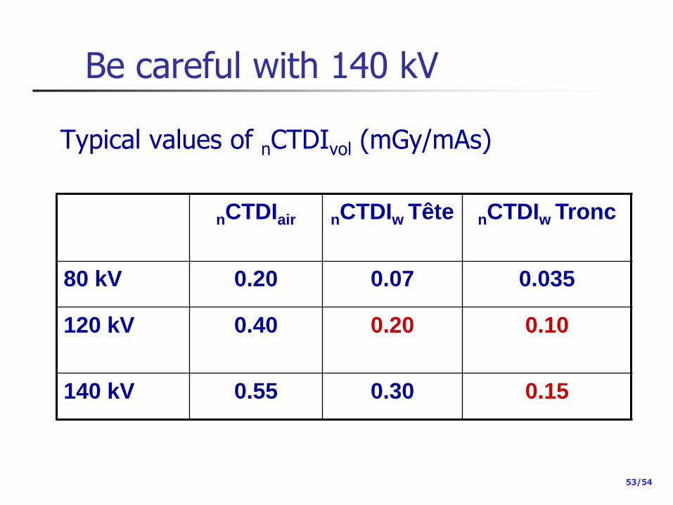
Be careful with 140 kV
53/54
nCTDIair nCTDIw Tête nCTDIw Tronc
80 kV 0.20 0.07 0.035
120 kV
0.40 0.20 0.10
140 kV 0.55 0.30 0.15
Typical values of nCTDIvol (mGy/mAs)
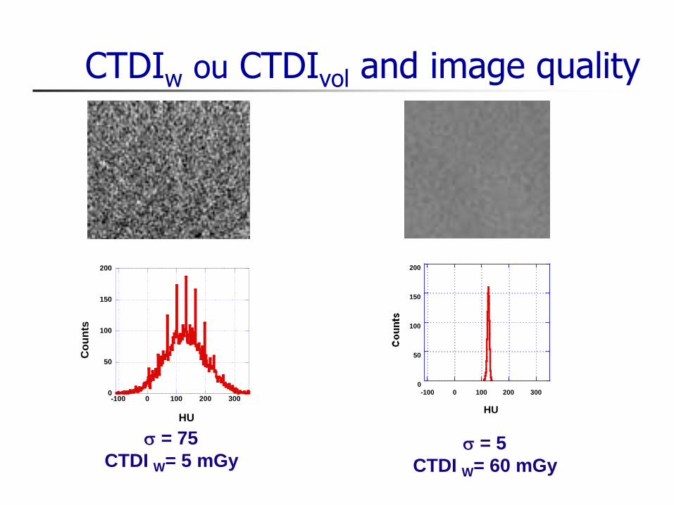
CTDIw ou CTDIvol and image quality
0
50
100
150
200
-100 0 100 200 300
HU
0
50
100
150
200
-100 0 100 200 300
Co
un
ts
HU
s = 75
CTDI W= 5 mGy s = 5
CTDI W= 60 mGy
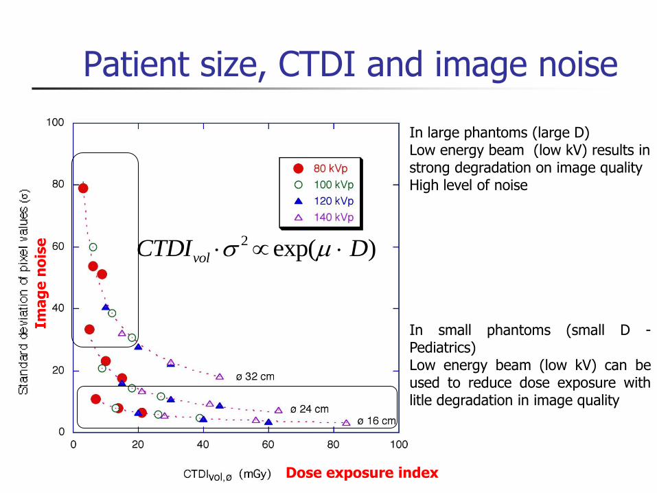
Patient size, CTDI and image noise
2 exp( )volCTDI Ds
In small phantoms (small D - Pediatrics) Low energy beam (low kV) can be used to reduce dose exposure with litle degradation in image quality
In large phantoms (large D) Low energy beam (low kV) results in strong degradation on image quality High level of noise
Ima
ge
no
ise
Dose exposure index
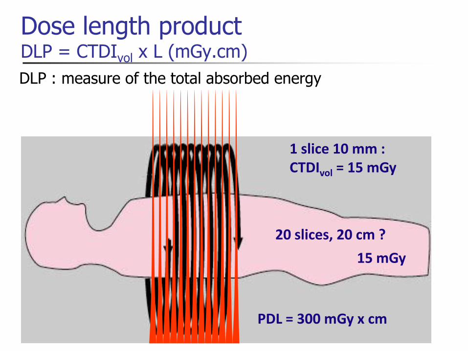
Dose length product DLP = CTDIvol x L (mGy.cm)
1 slice 10 mm : CTDIvol = 15 mGy
PDL = 300 mGy x cm
20 slices, 20 cm ?
15 mGy
DLP : measure of the total absorbed energy
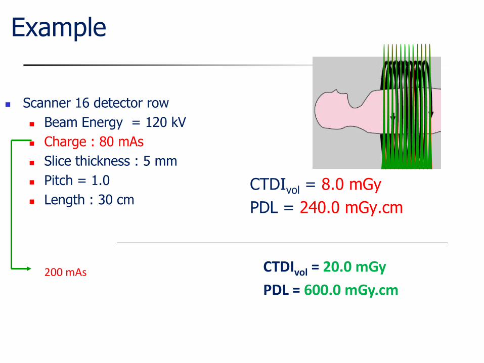
Example
Scanner 16 detector row
Beam Energy = 120 kV
Charge : 80 mAs
Slice thickness : 5 mm
Pitch = 1.0
Length : 30 cm CTDIvol = 8.0 mGy
PDL = 240.0 mGy.cm
CTDIvol = 20.0 mGy
PDL = 600.0 mGy.cm 200 mAs

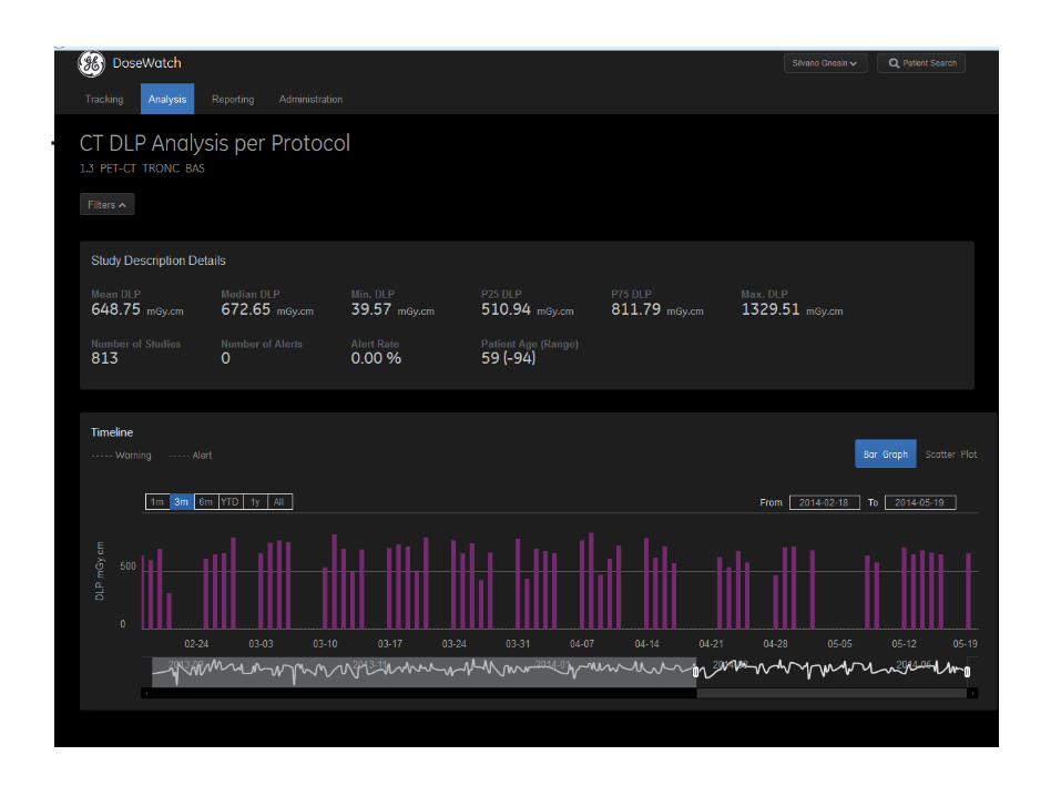
Where to find the information
58/54
CTDI : average dose within a slice image noise level
DLP : total number of photons Effective dose

CT : what is low dose ?
59/54

Dose reference levels (DRL) – NRD - DRW

DRL CT in nuclear medicine (PET/CT) Survey 2016/2017
61/53

62/53
DRL CT in nuclear medicine (SPECT/CT) Survey 2016/2017

SSDE (Size Specific Diameter equivalent)
Scout acquisition Equivalent diameter
AAPM Report No. 204
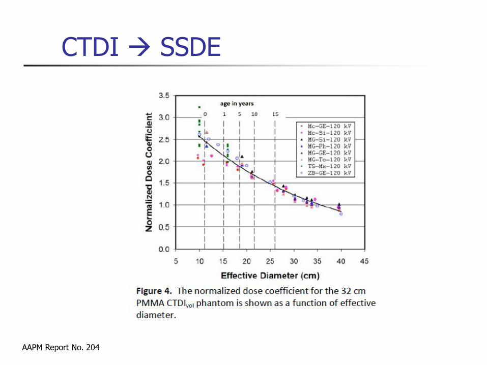
AAPM Report No. 204
CTDI SSDE

2010 survey – SPECT/CT*
65/54
< CTDIvol > : 2.3 mGy
domaine : 1 – 10 mGy
< PDL > : 56 mGy.cm
Domaine : 20 – 400 mGy.cm
E : 1.0 mSv [0.3 – 6.8]
*Hans Roser, Basel, preliminary results

2010 survey – PET/CT*
66/54
*Hans Roser, preliminary results
< CTDIvol > : 5.5 mGy
Domaine : 1 – 15 mGy
< PDL > : 456 mGy.cm
Domaine : 20 – 1400 mGy.cm
E : 7.8 mSv [0.3 – 23.8]

67/53
Annexe 4
L-08-01 CPR-PDL Long. CTDIv ol Long. CTDIv ol
NRD [MBq] [mGy.cm] [mm] [mGy] [mm] [mGy]
Tc-99m Colonne
vertébrale
264-275 350 664 542 8.16
DPD/MDP/H
DP
Bassin/hanc
he
274 220 306 (3) 253 8.26
Cf. Annexe 3
Genoux 98 100 306 (3) 253 8.26
Pieds 98-233 100 306 (3) 253 8.26
Parathyroïde 555 490 Tc-99m MIBI Cou 98 100 235 (5) 237 10.1 194 111.1 5.72
Poumon 180 148 Tc-99m
MAA
Thorax 275-946 120 314 72 2.29 315 94 2.98
Tc-99m MIBI
(1) (Cardiolite) 130-180
Cf. Annexe 3
Tc-99m ECD
(Neurolie)
Récepteurs
tumoraux
200 Cf. Annexe 3 I-123 MIBG Thorax et
abdomen
319-389 140 432 142 3.29 419 125 2.98
In-111
Octreoscan
388 115.7 2.98
2.98 (4)125 (4)419 (4)
CHUV - GE Infinia Hawkeye 4
PDL
[mGy.cm]
2.9
CPR CHUV - GE Discovery 670
Récepteurs
tumoraux
180 Cf. Annexe 3 Thorax et
abdomen
319-389 140 410 119
Cerveau 800 (2) Crane 160-239 180
Système
osseux
700
Myocarde 300+900 Partie
inferieure du
thorax
ExamenActivité appl.
70kg [MBq]
Produit
Radiopharm
aceutique
Partie du
corps
CPR Long.
[mm]
PDL
[mGy.cm]
(1) L’imagerie Myocardique en SPECT/CT n’est plus d’actualité au sein du service. A sa place PET/CT Rb82 .(2) L’imagerie SPECT du cerveau adopte une correction de l'atténuation basée sur la méthode de Chang. Le CT n’est pas effectué.(3) Champ de vue souvent étendu pour correspondre au champ de vue de la gamma-caméra.(4) Procédure standard pour la correction d'atténuation et le repérage anatomique. Longueur de scan correspondant au champ de vue de la gamma caméra. Le rapport PDL / Longueur reste largement à l'avantage du protocole CHUV.(5) Procédure pré-chirurgicale. Champ de vue étendu pour les besoins du chirurgien. Rapport PDL / Longueur constant.

69/53
From DLP to effective dose
PDL 1 = CTDIw x L1
L1
PDL 2 = CTDIvol x L2
L2
PDL 3 = CTDIvol x L3 L3
Conversion factor =
E = S Ei
x 0.0023 = E1
x 0.0054
x 0.017
x 0.015
x 0.019
= E2
= E3
Dose length product x Effective dose
70/58
Conclusion
Problems
Some manufacturers are reluctant to perform the required tests
Check If requirements are fulfilled
If range of acceptance values are provided (especially for stability tests)
Acceptance test included in purchase contract
Be careful when quoting “low dose” CT
Advantages
Strategy compatible with international standards
Quantitative measurements available
Stability tests : simple and not time consuming