FME for Data Analytics Workflows - Safe...
127
FME ® for Data Analytics Workflows Training Manual 2013-SP3 Edition
Transcript of FME for Data Analytics Workflows - Safe...

FME® for Data Analytics Workflows
Training Manual 2013-SP3 Edition

ii
Safe Software Inc. makes no warranty either expressed or implied, including, but not limited to, any implied warranties of merchantability or fitness for a particular purpose regarding these materials, and makes such materials available solely on an “as-is” basis.
In no event shall Safe Software Inc. be liable to anyone for special, collateral, incidental, or consequential damages in connection with or arising out of purchase or use of these materials. The sole and exclusive liability of Safe Software Inc., regardless of the form or action, shall not exceed the purchase price of the materials described herein.
This manual describes the functionality and use of the software at the time of publication. The software described herein, and the descriptions themselves, are subject to change without notice.
Any spatial data included in this material is intended for training use only. It is not meant to accurately reflect any real life situation and may have been altered in some way from the original source data.
Much of the data used here originates from public domain data made available by the City of Austin and Travis County, Texas. The datasets can be found at: ftp://ftp.ci.austin.tx.us/GIS-Data/Regional/coa_gis.html
Copyright © 1994–2013 Safe Software Inc. All rights are reserved.
Revisions Every effort has been made to ensure the accuracy of this document. Safe Software Inc. regrets any errors and omissions that may occur and would appreciate being informed of any errors found. Safe Software Inc. will correct any such errors and omissions in a subsequent version, as feasible. Please contact us at:
Safe Software Inc. Suite 2017, 7445 – 132nd Street Surrey, BC Canada V3W1J8
fax: 604-501-9965 e-mail: [email protected]
www.safe.com
Safe Software Inc. assumes no responsibility for any errors in this document or their consequences, and reserves the right to make improvements and changes to this document without notice.
Trademarks FME® and SpatialDirect® are registered trademarks of Safe Software Inc. All brand or product names are trademarks or registered trademarks of their respective holders and should be noted as such.
Document Information Document Name: FME for Data Analytics Workflows FME Version: FME Desktop 2013-SP3 Build 13528 32-bit Operating System: Windows 7 SP-1, 64-bit Updated: August 2013

FME Desktop Training Manual
Welcome to Safe Software
Course Overview ............................................................................................................................. iii
Who Am I? .............................................................................................................................................. iii Certified FME Trainers ............................................................................................................................ iii Course Goal ............................................................................................................................................ iii Course Structure ..................................................................................................................................... iii FME Version ........................................................................................................................................... iii Sample Data ........................................................................................................................................... iii
About the Manual ............................................................................................................................ iv Icons ....................................................................................................................................................... iv
Course Resources ............................................................................................................................ v On Your Training Computer ..................................................................................................................... v On Your Virtual Machine .......................................................................................................................... v Course Etiquette ...................................................................................................................................... v
About Safe Software ....................................................................................................................... vi History of Safe Software ......................................................................................................................... vi The Safe Software Vision… .................................................................................................................... vi The Safe Software Mission Statement… ................................................................................................ vi
Introductions ................................................................................................................................... vii Who are you?......................................................................................................................................... vii What formats interest you? .................................................................................................................... vii What do you hope to achieve during this course? ................................................................................. vii Have you used FME before? ................................................................................................................. vii

FME Desktop Training Manual
ii Course Overview

FME Desktop Training Manual
Course Overview iii
Course Overview This is an introductory-level, general training course for users of FME working on Data Analytics workflows
Who Am I? This is the instructor’s chance to introduce herself or himself. Certified FME Trainers Your FME training instructor may possess FME certified trainer status, indicating Safe Software’s guarantee of quality for your FME training course. If you have comments or concerns about your training then please contact us via our website (www.safe.com/contact), or else through our Training Manager directly at [email protected] Course Goal This training course provides a framework for understanding FME, upon which a user can base their work. We find users come to master one function, but go home with many new FME uses! The training will introduce basic concepts and terminology, help students become efficient users of FME, and direct you to resources to help apply the product to your own needs. Course Structure The course is made up of three main sections. These sections are:
• Data Translation Basics • Data Transformation • Translation Components
The instructor may choose to cover as many of these sections as they feel are required, or possible in the time permitted. They may also cover the course content in a different order and will skip or add new content to better customize the course to your needs FME Version This training material is designed specifically for use with FME2013-SP3. You may not have some of the functionality described if you use an older version of FME. Sample Data The sample data required to carry out the examples and exercises in this document can be obtained from: www.safe.com/fmedata

FME Desktop Training Manual
iv About the Manual
About the Manual The FME Desktop training manual and exercise workbook are yours to keep. They include detailed material to help you remember your training.
This manual forms the basis for FME Desktop training – in-person or online – but is also useful reference material for future work you may undertake with FME. Icons In the training manual you may see the following icons… Tip: Additional advice to help apply the knowledge you have learned.
Caution: A warning where misuse of FME could lead to difficulties.
Example or Exercise: An example or exercise that the instructor will use to demonstrate a particular point or feature of FME. You may work through the example with the instructor or on your own.
Advanced Exercise: Extra challenges for students who are quick to finish and want to take an exercise a little bit further.
New: A feature new to, or significantly changed in, the most recent version of FME. Q&A: Questions about the course content and how it is applied.
Important hints and tips appear in a box like this, to separate them from ordinary content. Also, people from the city of Interopolis will also appear from time-to-time to give you advice and dispense FME-related wisdom.

FME Desktop Training Manual
Course Resources v
Course Resources A number of sample datasets and workspaces will be used in this course.
On Your Training Computer The data used in this training course is based on datasets from the fictional City of Interopolis. Most exercises ask you to assume the role of a city planner and solve a particular problem using both the City’s corporate data and data provided by external agencies. Resources for the examples and exercises in the manual can be found at the following locations:
Location Resource
C:\FMEData\Data Datasets belonging to the City of Interopolis and local organizations and companies
C:\FMEData\Resources Resources used in the training such as datasets that don’t fit into the City of Interopolis
C:\FMEData\Workspaces Workspaces used in the student exercises. There are subfolders for each session
C:\FMEData\Output The location in which to write exercise output. There are subfolders for each session
< documents>\My FME Workspaces The default location to save FME workspaces On Your Virtual Machine If you are taking FME Desktop training online, you may be provided with a virtual machine hosted in the cloud. If so, you should find all of the above resources, plus a copy of the FME release used in the training, just as if you were working on a physical computer. You should also find a digital copy of this manual, either on the computer desktop or in the documents folder. Please alert your instructor if any item is missing from your setup. Course Etiquette For online courses, please consider other students and test your virtual machine connection before the course starts. The instructor cannot help debug connection problems during the course!
For live courses, please respect other students’ needs by keeping noise to a minimum when using a mobile phone or checking e-mail.

FME Desktop Training Manual
vi About Safe Software
About Safe Software Safe Software: Achieve total spatial data mastery!
History of Safe Software Safe Software Inc. is the maker of FME® and the global leader in spatial data transformation technology that helps GIS professionals and organizations master their data interoperability challenges. A common question is, “where did the names ‘Safe Software’ and ‘FME’ come from?” Safe Software was founded way back in 1993 by Don Murray and Dale Lutz. Back then, there was a format called the Spatial Archive and Interchange Format (SAIF). Since “SAIF” is pronounced “safe,” we decided to take the name Safe Software as a play on the SAIF format name. FME officially stands for the Feature Manipulation Engine, and reflects its ability to transform data. By 2008, we had shortened it to “FME,” since by then most everyone knew what we were talking about, and to be honest, it was a mouthful. Another common question is, “what happened to your hair?”, but that’s a story for another time! Today, FME is used by thousands of customers in over 116 countries in a wide variety of industries. Our channel partner network has more than 100 value-added resellers across six continents. The Safe Software Vision…
The Safe Software Mission Statement…
‘Our vision is to be the global leader in spatial data transformation, to knock down every last barrier to free and unrestricted spatial data use.’
‘Our mission is to help organizations use spatial data more easily and efficiently.’

FME Desktop Training Manual
Introductions vii
Introductions Safe Software’s standalone, web-based, and embedded software products are used by a worldwide network of clients from a wide range of organizations and industries.
Who are you? What formats interest you? What do you hope to achieve during this course? Have you used FME before? This is your chance to introduce yourself to the rest of the class. You may want to mention the organization you represent, what experience you have using FME, and which formats and functionality you’re most interested in.
Please think of the environment and don’t print this manual unless you really need to. Using a digital copy or sharing with a colleague will help save paper. And don’t forget to recycle printed copies when you are finished with them!
You can find an online version of this manual by browsing the Safe Software training catalog at:
http://www.safe.com/learning/training/course-schedule/course-catalog/ …and clicking on the links marked “Resource Centre”.

FME for Data Analytics Workflows Training Manual
Data Translation Basics
Introduction to FME ................................................................................................................................. 3
What is FME? ................................................................................................................................................. 3 How Does FME Work? ................................................................................................................................... 3
FME Editions and Licensing.................................................................................................................... 4 FME Desktop Editions .................................................................................................................................... 4 FME Licensing ................................................................................................................................................ 4 Operating Systems ......................................................................................................................................... 4
FME Desktop Components ..................................................................................................................... 5 FME Applications ............................................................................................................................................ 5 Other FME Components ................................................................................................................................. 5
Introduction to FME Workbench ............................................................................................................. 6 What is FME Workbench? .............................................................................................................................. 6 Major Components of FME Workbench .......................................................................................................... 7 Window Control .............................................................................................................................................. 8 Generating a Translation .............................................................................................................................. 10 The New Workspace..................................................................................................................................... 10
Appendix A ............................................................................................................................................ 15 Useful Terminology ....................................................................................................................................... 15

FME for Data Analytics Workflows Training Manual
Page 1-2 Data Translation Basics

FME for Data Analytics Workflows Training Manual
Data Translation Basics Page 1-3
Introduction to FME
FME is specifically designed for Data Transformation. Its key characteristics illustrate why it is so suitable for this role.
What is FME? FME (Feature Manipulation Engine) was designed as a Data Transformation tool to break down barriers to spatial data interoperability. In fact, it is often classed as a Spatial ETL application. ETL stands for Extract, Transform and Load. It is a data warehousing tool that extracts data from a source, transforms it to fit the users’ needs and loads it into a destination or data warehouse. A Spatial ETL tool is the geographic equivalent of ETL. While an ETL tool will process the various column types that are in a non-spatial database or system, a Spatial ETL tool must also have the spatial operations - geoprocessing capabilities that change the structure and representation of spatial data – needed to move data from one spatial database or GIS to another. How Does FME Work? FME has a number of key characteristics: Centralized FME is a central engine among an array of supported format. Data can be read from any format and written to any other. Adding support for a new format is as simple as plugging it into the FME engine. FME can support both raster and vector formats (among many others) under the same centralized model. Semantic FME has a rich data model designed to cover all possible geometry and attribute types. When limitations in the destination (output) format cause incompatibility, FME automatically compensates to create a seamless translation process. Transformational The ‘T’ in ETL is what plain format-translation tools lack. FME provides tremendous transformation functionality, resulting in output that can be much greater than the sum of the inputs, and allowing data to be transformed from one type (for example, GIS) to another (for example, CAD).

FME for Data Analytics Workflows Training Manual
Page 1-4 Data Translation Basics
FME Editions and Licensing
FME comes in a range of different editions that vary according to the needs of the user.
FME Desktop Editions FME is available in a number of editions. Each edition has a different set of functions and formats available, but includes all the features from lesser editions. FME Base edition This is an entry-level FME edition that supports 40 formats and a set of basic transformation tools. FME Professional edition This is a general purpose FME edition with more formats and the full set of transformation tools. Esri/Intergraph editions These editions add support for formats tied to a specific application; for example the Esri edition includes support for Geodatabase and the Intergraph edition support for writing GeoMedia. Oracle/SQL Server/DB2 editions These editions add support for mostly database formats; for example the Oracle edition includes support for writing to Oracle Spatial databases. Smallworld This edition adds support for GE Smallworld reading and writing. Always check www.safe.com for the latest info on which editions support which formats. FME Licensing A common mistake is to think each edition is a different download/installer file. This is not true. All editions of FME Desktop have the same installer, with different functionality being unlocked by different licenses. FME has two licensing methods: Node-Locked (Fixed) License A node-locked license is for use with FME on a specific computer only. The license cannot be transferred to another computer except by a special request to Safe Software. Floating (Concurrent) License Floating licenses are held on a server and issued to individual users as they start up FME. This is useful for the situation where there are many FME users, but not all using FME at the same time. Operating Systems FME is available on both 32 and 64-bit platforms. See the web site for more information on 64-bit.

FME for Data Analytics Workflows Training Manual
Data Translation Basics Page 1-5
FME Desktop Components FME comprises a number of spatial data handling components. Everything here is included with every edition of FME Desktop.
FME Applications There are three key applications within the FME Desktop suite; FME Workbench, FME Data Inspector, and FME Quick Translator. FME Workbench FME Workbench has an intuitive point-and-click graphic interface to enable translations to be graphically described as a flow of data. FME Workbench is the primary tool for data translations in FME.
FME Data Inspector The FME Data Inspector utility allows quick viewing of data in any of the FME supported formats. It is used primarily for data validation and quality assurance by allowing the previewing of data before translation or its reviewing after translation.
FME Quick Translator The FME Quick Translator is used for quick format translations, or for running more sophisticated translations created in FME Workbench. Other FME Components Additional components are also included as part of FME Desktop (Professional Edition or higher). FME Command Line Engine The FME Command Line Engine enables translations to be initiated at the command line level. FME Application Extenders FME Application Extenders are FME components embedded into other GIS applications. These commonly enable a GIS product to view datasets not native to that application. FME Plug-In SDK The FME Plug-In SDK allows developers to add formats and functionality to the FME core.

FME for Data Analytics Workflows Training Manual
Page 1-6 Data Translation Basics
Introduction to FME Workbench Workbench is FME’s primary tool for data translations. Its intuitive point-and-click graphic interface allows translations to be graphically described as a flow of data.
What is FME Workbench? FME Workbench is an application for defining data translation and transformation processes. With Workbench, underlying FME functionality is exposed in an intuitive interface that allows users to graphically define a custom dataflow from source, through transformation, to destination. Workbench has tools for defining the source and destination dataset structure (or schema), and also for manipulating the geometry and attributes of spatial data. Workbench is fully integrated to interact with other FME applications such as the FME Data Inspector and other products such as FME Server, and is the authoring tool for FME Server models. Starting FME Workbench Find FME Workbench in the FME Desktop sub-menu in the Windows start menu. Click on the sub-menu entry to start Workbench.
Workbench is located under the FME Desktop entry in the Windows start menu.
When FME Workbench starts, it opens with a startup screen shown as a tabbed window. This window has shortcuts to tools for defining a translation, and also shows information to help get users started with FME.
The startup tab links to a live web page and therefore the display will change over time as new information and resources are shown. A second tab – Main – displays a canvas where the actual translation will be graphically defined.

FME for Data Analytics Workflows Training Manual
Data Translation Basics Page 1-7
Major Components of FME Workbench The FME Workbench user interface has a number of major components.
Menu bar and Toolbar The menu bar and toolbar contain a number of tools: for example, tools for navigating around the workspace, controlling administrative tasks, and adding or removing Reader (source) datasets. Canvas The FME Workbench canvas is where users graphically define a translation. This definition is called a “workspace” and can be saved for re-use later. By default the workspace reads from left to right; data source on the left, transformation tools in the center, and data destination on the right. Connections between each item represent the flow of data and may branch in different directions or even lead to a dead-end if required.
Navigator The navigator is an explorer type tool that is used to define source and destination datasets, plus all other parameters that apply to reading and writing these datasets. Transformer Gallery The transformer gallery is a tool for the location and selection of FME transformation tools. Translation Log The log window (translation log) shows a report on translation results. Information includes any warning or error messages, translation status, length of translation, and number of features processed. Overview Window (Not shown above) The overview window shows a small-scale view of the current FME workspace, and is therefore most useful when a large workspace is being worked upon.
Terminology: To be precise the application itself is called Workbench, but the process defined in the canvas window is called a “Workspace”. The terms are so similar that they are easily confused. The difference is minor so it doesn’t really matter, but listen to certain instructors grind their teeth when you get it wrong!

FME for Data Analytics Workflows Training Manual
Page 1-8 Data Translation Basics
Window Control All windows in the Workbench interface can be detached from a fixed position and deposited in a custom location by clicking on the frame of the window and dragging it into a new position. The windows can even float outside of the main Workbench window.
Stacking windows (such as the Navigator and Transformer Gallery) means one appears either vertically above the other (on the left or right hand side of Workbench) or horizontally next to each other (at the top or bottom of Workbench). The functionality to stack or tab windows is controlled by the way the window is dragged and dropped into a new position. If a window is dragged and dropped on top of an existing window, then the two will become tabbed. If a window is dragged and dropped beside an existing window (or between two existing windows), then they will become stacked. Here a user is stacking the Transformer Gallery between two other windows on the left-hand side of Workbench.
Here a user is choosing to arrange the Transformer Gallery and Log Window in a tabbed configuration.
The result will look like this:
Functionality: The F11 button toggles the Workbench canvas between full screen mode and back again. Shift+F11 does the same thing, but leaves the menubar and toolbar available for use. Try it and see for yourself!

FME for Data Analytics Workflows Training Manual
Data Translation Basics Page 1-9
Miss Vector says… ‘Attention please! It’s time for a quiz to see what you’ve learned so far. Turn to a fellow student and answer these questions between you.’
Which of the following words describe FME Desktop? 1) Distributed 2) Semantic 3) Transformational 4) Centralized Which of the following applications are parts of FME Desktop? 1) FME Workbench 2) FME Server 3) FME Quick Translator 4) FME Data Inspector Which of the following tools is not found in FME Workbench? 1) A data inspection tool 2) A source data selection tool 3) A destination data selection tool 4) Data manipulation tools Which of the following windows are on the Workbench interface? 1) Navigator 2) Transformer Gallery 3) Log Window 4) Display Control Window

FME for Data Analytics Workflows Training Manual
Page 1-10 Data Translation Basics
Generating a Translation The Generate Workspace dialog condenses all the initial translation choices into a single dialog box. This is the preferred workspace creation tool. It can be accessed through the Getting Started menu in the Workbench start tab, or by using the shortcut key Ctrl+G.
The Generate Workspace dialog has fields for the Reader and Writer Formats and Datasets. These prompts have a drop-down menu and ‘Intelli-complete’ properties to assist in selecting a format. The red fields indicate mandatory fields. Users must enter data in these fields to continue. Notice that the OK button is de-activated until the mandatory fields are complete. There are also buttons for checking and/or altering parameters for each dataset, and a button for previewing the data in the FME Data Inspector.
Feature Types Dialog Whichever method of workspace creation is used, whenever a Reader (source) Dataset contains a number of different layers the user is prompted to select which layers they want to translate. This is achieved through the Select Feature Types dialog. In FME ‘Feature Type’ is another term for ‘layer’. Only selected layers show in the workspace. Here, for example, the user has chosen to include all available layers within the workspace:
It’s always worth checking the parameters at this point. Although most parameters are exposed in the Workbench Navigator window, and can be set there, some parameters affect how the translation workspace will be created and so need adjusting before you accept this dialog.
Terminology: In most cases FME uses the terms ‘Reader’ and ‘Writer’ instead of ‘Source’ and ‘Destination’. Session 3 explains the why. For now, just note that a Reader reads datasets and a Writer writes datasets, and these terms are analogous to source/destination and input/output.
In the Generate Workspace dialog, why might it be useful to set the data format before browsing for the source data? Try browsing for a dataset before setting the format type and see if you can detect the difference.

FME for Data Analytics Workflows Training Manual
Data Translation Basics Page 1-11
The New Workspace A new workspace reads from left to right, from a Reader, through a transformation, to a Writer. One could also think of these as the Extract-Transform-Load stages of a spatial ETL process. A new workspace resembles this example. FME places annotation to emphasize the E-T-L structure (Source > Flow > Destination). Arrows denote the direction of data flow, from source to destination. Running the Translation The green arrow (or ‘play’ button) on the Workbench toolbar starts a translation.
There are also options under File on the menu bar to either ‘Run’ or ‘Prompt and Run’ a translation. The File menu with run options include shortcut keys that can be used – the F5 key to simply run a translation and Ctrl+R to prompt and run a translation. Saving the Translation Workspaces can be saved to a file so that they can be reused at a later date. Simply use File > Save (shortcut = Ctrl+S) or File > Save As… to save the translation. The default file extension is .fmw. Double-clicking a *.fmw file in Explorer starts FME Workbench and opens up the workspace.
Firefighter Mapp says…
‘The file menu (File > Open Recent) shows a list of previously used workspaces. This list is expandable to up to a towering 15 entries.’
Functionality: The ‘Run’ option carries out a translation using the same parameters and settings used previously. The ‘Prompt and Run’ option prompts for new values for parameters and settings. Regardless of this, however, the ‘Run’ option must still prompt for parameters that have not yet been filled in and don’t have default values.

FME for Data Analytics Workflows Training Manual
Page 1-12 Data Translation Basics
Translation Results After running a translation statistics relating to the output results are found in the Workbench log window. The translation log reveals whether the translation succeeded or failed, how many features were read from the source and written to the destination, and how long it took to perform the translation. In this example the log file reveals that 2319 features were read from a MicroStation dgn CAD file. These features were written to a GML output file. The overall process was a success (with 1 warning). The elapsed time for the translation was 4.6 seconds.
Terminology: When a translation is run immediately in Workbench or Quick Translator, without further adjustment, it’s known as a ‘Quick Translation.’ Because FME is a ‘semantic’ translator, with an enhanced data model, the output from a quick translation is as close to the source data in structure and meaning as possible.
Functionality: Text in the log window that represents a URL or Email address automatically gets a hyperlink added to it. That way you can just click on it in the log window to activate its target.

FME for Data Analytics Workflows Training Manual
Data Translation Basics Page 1-13
Let’s see how intuitive FME’s interface is by doing some example translations with minimal instruction. Start FME Workbench and use it to carry out this conversion of spatial data: Reader Format MapInfo TAB (MFAL) Reader Dataset C:\FMEData\Data\Parks\city_parks.tab Writer Format MapInfo MIF/MID Writer Dataset C:\FMEData\Output\DAOutput\ For now, ignore the Workflow Options and leave the default of ‘Static Schema’. Run the translation. Locate the destination data in Windows Explorer to prove that it’s been written.
Example 1: Quick Translation
Scenario FME user; City of Interopolis, Planning Department
Data City Parks
Overall Goal Translate the city parks data from MapInfo TAB to GML format
Demonstrates Quick Translation in FME Workbench
Finished Workspace C:\FMEData\Workspaces\DAManual\Example1aComplete.fmw C:\FMEData\Workspaces\DAManual\Example1bComplete.fmw
Functionality: You can easily locate the output from a translation by right-clicking on the Feature Type object on the canvas, and choosing the option “Open Containing Folder”

FME for Data Analytics Workflows Training Manual
Page 1-14 Data Translation Basics
The Generate Workspace dialog has two important buttons that can be used to check the Parameters being used. So now let’s try a translation of non-spatial data, using these parameters to affect how the data is read and written. Start FME Workbench and open the Generate Workspace dialog (Ctrl+G) to define this translation: Reader Format Comma Separated Value (CSV) Reader Dataset C:\FMEData\Resources\XML\FMECourses.csv Writer Format Microsoft Excel Writer Dataset C:\FMEData\Output\DAOutput\Courses.xls Before closing the dialog, click on the Parameters button for the CSV Reader:
Notice that there are a great number of parameters that can be set at this point. For now click the option “File Has Field Names”. Pay particular attention to the difference that parameter makes to the CSV File Preview. Click OK to close the Reader parameters dialog. Now click the Excel Writer Parameters button. There are fewer parameters for the Excel writer, but they are no less important. In particular the ability to add data (by setting Overwrite Existing File to No) is very useful, as is the parameter to use an existing spreadsheet as a template file.
Keep the existing parameters and click OK to close the dialog. Click OK again to generate the workspace. Save the workspace (Ctrl+S) and then run it (Ctrl+R). Examine the output (and compare it to the input) to ensure it is correct.

FME for Data Analytics Workflows Training Manual
Data Translation Basics Page 1-15
Appendix A
There are many terms used in FME that may not be familiar to you. This Appendix to the training manual is intended to help.
Useful Terminology Here’s a short list of terms that are commonly used in the world of FME: Canvas The window in FME Workbench in which Workspaces are created. Dataset A set of data with a common theme. A file, folder, database, etc. Feature The smallest item of data. May also be known as an object, entity, or element. Feature Connection A connection between different objects in a Workspace. Feature Type A collection of features in a Dataset. May also be known as a layer, level, table, feature class, category, or feature object. FME Data Inspector A tool for inspecting spatial and non-spatial datasets FME Workbench A tool for creating Workspaces to translate and transform spatial and non-spatial datasets Transformers Tools in FME Workbench that are used in a Workspace to transform (manipulate, modify, etc.) features, their geometry, or their attributes. Workspace A model for translating and transforming data, defined as a data flow diagram in the Canvas window of FME Workbench.

FME for Data Analytics Workflows Training Manual
Data Transformation
Data Transformation ......................................................................................................................... 3
What is Data Transformation? ................................................................................................................. 3 Data Transformation Types ..................................................................................................................... 3
Structural Transformation ................................................................................................................. 4 Schema Concepts .................................................................................................................................... 4 Schema Editing ........................................................................................................................................ 5 Editable Components ............................................................................................................................... 6 Schema Mapping ..................................................................................................................................... 7 Feature Mapping in FME Workbench ...................................................................................................... 8 Attribute Mapping in FME Workbench ..................................................................................................... 8
Introduction to Data Inspection ....................................................................................................... 14 What is Data Inspection? ....................................................................................................................... 14
Introduction to the FME Data Inspector ......................................................................................... 14 What is the FME Data Inspector? .......................................................................................................... 15 Major Components of the FME Data Inspector ...................................................................................... 16
Using FME Data Inspector ............................................................................................................. 17 Viewing Data .......................................................................................................................................... 17 Inspecting Data ...................................................................................................................................... 18 Table View Window ............................................................................................................................... 19 Filtering Data.......................................................................................................................................... 20 Display Control....................................................................................................................................... 21
Data Inspection Using FME Workbench ........................................................................................ 24 Using an Inspector Transformer............................................................................................................. 24 Placing an Inspector Transformer .......................................................................................................... 24
Transformation Using Transformers............................................................................................... 26 What is a Transformer? ......................................................................................................................... 26 Transformer Parameters ........................................................................................................................ 26 Color-Coded Properties Buttons ............................................................................................................ 27 Transformer Ports .................................................................................................................................. 28
Content Transformation .................................................................................................................. 29 What is a Feature? ................................................................................................................................. 29 Geometric Transformation ..................................................................................................................... 30 Attribute Transformation ........................................................................................................................ 31
Transformers used in Series .......................................................................................................... 32 Chaining Transformers .......................................................................................................................... 32
Transformer Handling ..................................................................................................................... 35 Transformer Gallery ............................................................................................................................... 35 Quick Add .............................................................................................................................................. 36 Drag-and-Insert ...................................................................................................................................... 37 Quick Connect ....................................................................................................................................... 38 Transformer Description Window ........................................................................................................... 40 Transformer Deletions ........................................................................................................................... 42
Transformers used in Parallel ........................................................................................................ 43 Multiple Streams .................................................................................................................................... 43
Coordinate System Transformation................................................................................................ 47 Coordinate System Basics ..................................................................................................................... 47 Coordinate System Settings .................................................................................................................. 47

FME for Data Analytics Workflows Training Manual
Page 2-2 Data Transformation

FME for Data Analytics Workflows Training Manual
Data Transformation Page 2-3
Data Transformation Data Transformation is the ability to manipulate data during Format Translation – even to the extent of having an output greater than the sum of the inputs!
What is Data Transformation? Data Transformation is FME’s ability to manipulate data. The transformation step occurs during the process of format translation. Data is read, transformed, and then written to the new format; the classic ETL (Extract-Transform-Load) configuration, as shown in the graphic below. Notice here how the attributes A, B, and C are transformed into a new set of attributes called W, X, Y and Z. The arrows indicate the translation is also bi-directional.
Sometimes FME automatically manipulates the data, as part of its semantic capabilities, renaming attributes, adjusting geometry, and splitting up data into several layers in order to ensure that the output from a Format Translation meets the specification of the destination format. Data Transformation Types Data transformation can be subdivided into two distinct types: Structural Transformation and Content Transformation. Structural Transformation This type of transformation is perhaps better called ‘reorganization’. It refers to the ability of FME to channel data from source to destination in an almost infinite number of arrangements. This includes the ability to merge data, divide data, re-order data, and define custom data structures. Transforming the structure of a dataset is carried out by manipulating its schema. Content Transformation This type of transformation is perhaps better called ‘revision’. It refers to the ability to alter the substance of a dataset. Manipulating a feature’s geometry or attribute values is the best example of how FME can transform content. Content transformation can take place independently or alongside structural transformation.

FME for Data Analytics Workflows Training Manual
Page 2-4 Data Transformation
Structural Transformation Transforming a dataset’s structure requires knowledge of schemas and how to use FME to manipulate them.
Schema Concepts A schema is the structure of a dataset or, more accurately, a formal definition of a dataset’s structure. The term Data Model may be more familiar, but at Safe Software we stick to the term ‘schema’. Each dataset has its own unique structure (schema) that includes feature types (layers), permitted geometries, user-defined attributes, and other rules that define or restrict its content. One could call this a ‘physical’ schema since it’s a physical representation of the data. How Does FME Represent Schemas? When a new workspace is created, FME scans all of the source datasets. From this it creates a visual representation of the data’s schema on the left side of the canvas. On the right side, it creates a visual representation of how this schema will be duplicated in the chosen output format. Here are source and destination schemas as they are represented in Workbench. Each object on the canvas is a separate Feature Type within a dataset. The workspace reads from left to right. At this point, the Reader schema represents ‘what we have’; that is, FME’s view of the source datasets. The Writer schema represents ‘what we want’; the data required by the user. To be technical, destination schemas could be called ‘logical’ schemas because they don’t physically exist at this point. Until the workspace is run, they’re just one potential output. By default, the Writer Schema is a mirror image of the source; differences only occur when demanded by limitations of the selected destination format. This allows Quick Translation to occur with no further editing of the translation by the user.
Source Dataset Schema Destination Dataset Schema
FME for Data Analytics Workflows Training Manual
Data Transformation Page 2-5
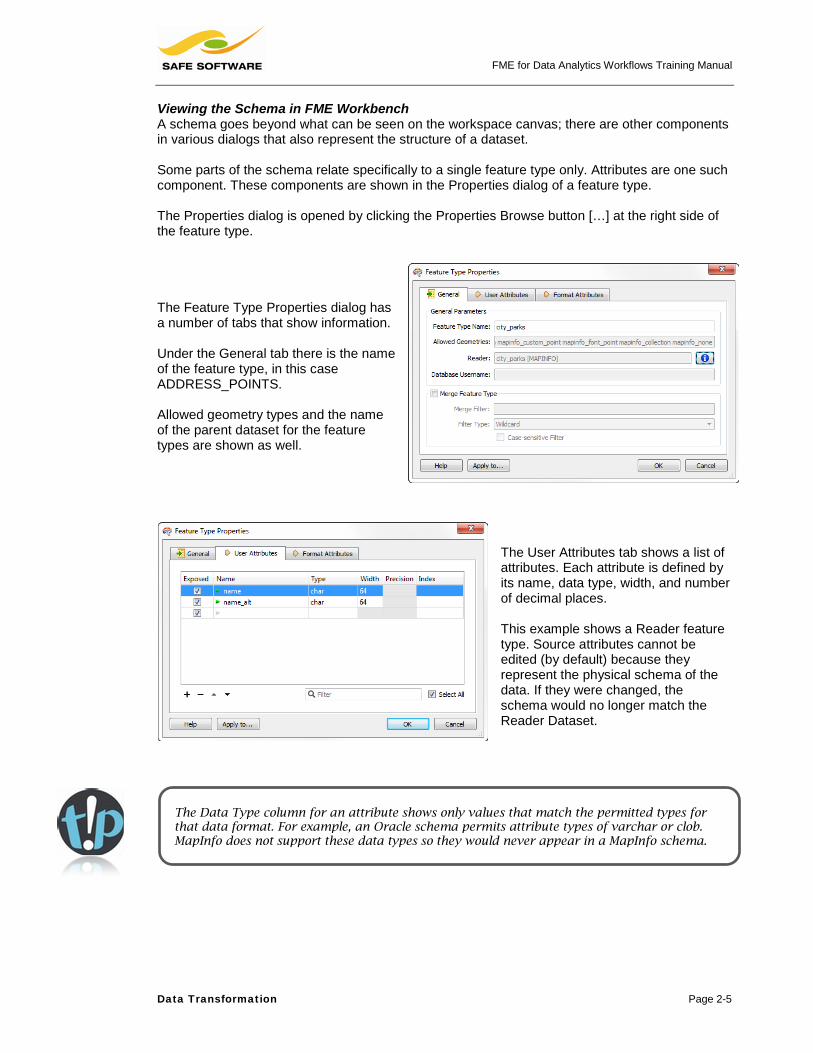
Viewing the Schema in FME Workbench A schema goes beyond what can be seen on the workspace canvas; there are other components in various dialogs that also represent the structure of a dataset. Some parts of the schema relate specifically to a single feature type only. Attributes are one such component. These components are shown in the Properties dialog of a feature type. The Properties dialog is opened by clicking the Properties Browse button […] at the right side of the feature type. The Feature Type Properties dialog has a number of tabs that show information. Under the General tab there is the name of the feature type, in this case ADDRESS_POINTS. Allowed geometry types and the name of the parent dataset for the feature types are shown as well.
The User Attributes tab shows a list of attributes. Each attribute is defined by its name, data type, width, and number of decimal places. This example shows a Reader feature type. Source attributes cannot be edited (by default) because they represent the physical schema of the data. If they were changed, the schema would no longer match the Reader Dataset.
The Data Type column for an attribute shows only values that match the permitted types for that data format. For example, an Oracle schema permits attribute types of varchar or clob. MapInfo does not support these data types so they would never appear in a MapInfo schema.

FME for Data Analytics Workflows Training Manual
Page 2-6 Data Transformation
Schema Editing As noted, initially the Writer Schema in a workspace is a mirror image of the source. However, in many cases the user requires the output to have a different data structure. Schema Editing is the process of altering the destination schema to customize the structure of the output data. One good example is renaming an attribute field in the output. After editing, the source schema still represents ‘what we have’, but the destination schema now truly does represent ‘what we want’. Editable Components There are a number of edits that can be performed, including, but not limited to the following. Attribute Renaming Attributes on the destination schema can be renamed, such as renaming ADDRESS to BUILDING_NUMBER. To rename an attribute open the Feature Type Properties dialog and click the User Attributes tab. Click the attribute to be renamed and enter the new name. Attribute Type Changes Any attribute on the writer schema can have a change of type; for example, changing ID from an integer to a float. To change an attribute type open the Feature Type Properties dialog and click the User Attributes tab. Use the Data Type field to change the type of an attribute.
Feature Type Renaming To rename a destination feature type (for example, rename ADDRESS_POINTS to ADDRESSES) open the Feature Type Properties dialog. Click the General tab. Click in the Feature Type Name field and edit the name as required. Geometry Type Changes To change the permitted geometry for a feature type, (for example, change the permitted geometries from lines to points) open the Feature Type Properties dialog. Click the General tab. Choose from the list of permitted geometries. Note: This field is only available where the format requires a decision on geometry type.
FME for Data Analytics Workflows Training Manual
Data Transformation Page 2-7
Schema Mapping Schema Mapping forms the basis for data restructuring. In FME Workbench, one side of the workspace shows the source schema (what we have) and the other side shows the destination schema (what we want). Initially the two schemas are automatically joined when the workspace is created, but when edits occur then these connections are usually lost. Schema mapping is the process of connecting the source schema to the destination schema in a way that ensures the correct Reader features are sent to the correct Writer feature types and the correct Reader attributes are sent to the correct Writer attributes. Feature Mapping Feature mapping is the process of connecting source feature types to destination feature types. Attribute Mapping Attribute Mapping is the process of connecting source attributes to destination attributes.
In Workbench’s intuitive interface, the most common way to make feature type and attribute connections is by dragging connecting lines between these parts of the schema. Domain Mapping Some formats support Domains, which are a way of defining what values are allowed in a particular attribute. With Coded Domains (where each value is given a Code Number), mapping is sometimes required to convert values from the Code number to the descriptive value, or vice versa. Domain mapping is also required when attributes need to change from one domain to another.
Ms. Analyst says…
‘You can think of Schema Editing and Mapping as reorganizing data.
A good analogy is a wardrobe full of clothes. When the wardrobe is reorganized you throw out what you no longer need, reserve space for new stuff that you’re planning to get, and move existing items into a more usable arrangement.
The same holds true for spatial data restructuring: it’s the act of reorganizing data to make it more usable”

FME for Data Analytics Workflows Training Manual
Page 2-8 Data Transformation
Feature Mapping in FME Workbench Feature Mapping is carried out by clicking the output port of a source feature type, dragging the arrowhead across to the input port of a destination feature type, and releasing the mouse button. Here a connecting line from source to destination feature type is created by dragging the arrowhead from the source to the destination. Attribute Mapping in FME Workbench Attribute Mapping is performed by clicking the output port of a source attribute, dragging the arrowhead to the input port of a destination attribute, and releasing the mouse button.
Here feature mapping has been carried out already and attribute connections are being made. Notice the green, yellow, and red color-coding that indicates which attributes are connected. Green ports indicate a connected attribute. Yellow ports indicate a source attribute that’s unconnected to a destination. Red ports indicate a destination attribute that’s unconnected to a source.
Feature mapping connections (or links) are shown with a thick, black arrow. Attribute mapping connections are shown with a thinner, gray arrow. Attributes with the same name in source and destination are connected automatically, even though a connecting line might not be visible; the port color is the key. Names are case-sensitive, therefore ROADS is not the same as roads or Roads It is permitted to map ‘what we have’ to ‘what we want’ in any way that is desired.
Here a user needs a single layer called Transportation in their output, and so is merging two input Feature Types (Rail and Roads) into one output Feature Type (Transportation).

FME for Data Analytics Workflows Training Manual
Data Transformation Page 2-9
Example 2 – Reading Data
Scenario FME user; City of Interopolis, Planning Department
Data CSV format dataset of Cell Phone towers
Overall Goal Create spatial data and extract information for use in Data Analytics
Demonstrates Reading data. Using a Transformer. Sending data for inspection.
Starting Workspace None
Finished Workspace C:\FMEData\Workspaces\DAManual\Example2Complete.fmw
Description This example is the first in a series that join together to create a larger FME-based project. The source data is a CSV dataset containing information about cell phone towers. Fields include signal quality plus an X/Y coordinate for each tower. The idea is to turn the CSV file contents into proper spatial data and create a set of statistical information from the attributes. Example 2 Reads the CSV dataset into FME and sets up parameters that control how the data is read. Converts X/Y coordinates into true spatial geometry and sets up sampling of the data. Example 3 Visually inspects the data against the backdrop of a base map of state/county boundaries. Example 4 Creates a grid suitable for aggregating the cell towers into groups for analysis Example 5 Aggregates data from the cell towers onto the grid square that they fall into Example 6 Reprojects the data so that grid size can be expressed as feet/metres, not decimal degrees. Example 7/8 Adds a writer to output the data to a MapInfo format, and previews what that output will look like. Example 9 Calculates statistics about the cell towers for use in Data Analytics workflows Example 10 Merges the cell tower statistical data onto the spatial (grid) features Example 11 Creates published parameters that give the end-user control over the translation process. Example 12 Provides further user control, cleans up the data schema, and styles the output data symbology

FME for Data Analytics Workflows Training Manual
Page 2-10 Data Transformation
1) Start Workbench Start FME Workbench if it isn’t already. If you already have a workspace open then select the option “Blank workspace” under “Getting Started” on the Start tab; otherwise just click on the tab marked “Main” It is common practice to build a translation from scratch, rather than using the Generate Workspace dialog. 2) Add the CSV File Open Windows Explorer and browse to the source data at: C:\FMEData\Resources\DA\CellSignal.csv Drag the file from the Explorer window and drop it onto the FME Workbench canvas. The “Add Reader” dialog will open and be filled in automatically with these parameters: Reader Format Comma Separated Value (CSV) Reader Dataset C:\FMEData\Resources\DA\CellSignal.csv Before the translation is created, we need to check the parameters for this Reader. Click on the “Parameters…” button to open the parameters dialog. Because the first line contains the field names for the data, put a check mark in the box labelled “File Has Field Names”.
Now set the “Maximum Lines to Scan” parameter to 1000. This speeds up creation of the workspace by limiting the amount of data scanned to determine the schema.
Because the CSV data includes spatial information – in the form of longitude and latitude attributes – we can have FME convert the data directly to a spatial form. To do so, locate “longitude” and “latitude” in the Attributes section of the dialog. Click in the Type field and change the attribute types to x_coordinate and y_coordinate respectively.
If all your datasets have field names then set this as the default and save time in the future.

FME for Data Analytics Workflows Training Manual
Data Transformation Page 2-11
Click OK to close the parameters dialog. Back in the Add Reader dialog, set the Coordinate System to LL84. Like a data format you can do this by typing in the name, selecting it from the drop-down list, or browsing for it in a gallery (click the […] button).
Leave the “Workflow Options” parameter as “Individual Feature Types”, although the “Single Merged Feature Types” option would also work for this translation. Click OK to close the dialog and add the Reader to the empty workspace.
The Feature Type added to the workspace should look like this:
If it looks like this then you forgot to check the “File Has Field Names” parameter.
If you do get this incorrect, you can fix the problem by deleting and then replacing the Reader. Ask your instructor if you need help.
3) Save the Workspace It’s important to save your workspace early on in the design process. This creates a recovery file and enables Workbench to back up the workspace periodically. Then, should anything untoward occur - like a power failure or operating system crash – you will be able to recover unsaved changes. So, save the workspace using File > Save from the menubar or the shortcut, Ctrl+S.

FME for Data Analytics Workflows Training Manual
Page 2-12 Data Transformation
4) Limit the number of features read For this example, we only want to read in some sample data – to ensure the translation works before reading the entire file. In the Navigator window, click on the expand icons to show the Advanced Parameters for the CSV Reader. Double-click on “Max Features to Read” and set it to 1000.
Terminology: Feature Type is the FME term that describes an identifiable subset of records. Common alternatives for this term are ‘layer’, ‘table’, ‘feature class’, and ‘object class’. Each layer of data in a dataset is represented by a separate Feature Type in the workspace. So a database with tables “Roads”, “Rivers”, and “Rail” is depicted by three Feature Types with those names. However, because CSV datasets have no way of internally subdividing data into layers, we call it a “fixed schema” dataset. There can be no layers in a CSV file so we simply call the Feature Type “CSV”.
Terminology: As you’ll see in the next section, there is a direct connection between the Feature Types on the canvas and the Reader in the Navigator window. Any Reader parameters you change in the Navigator have an effect on how the Feature Type is read.

FME for Data Analytics Workflows Training Manual
Data Transformation Page 2-13
5) Add Inspector Transformer A workspace can be run without having a Writer with which to create output. Instead the data can be transmitted directly to the FME Data Inspector application. Right-click on the title bar of the Reader feature type and select the option Connect Inspectors. An Inspector transformer is connected to the output port(s) of the feature type. Now, when data reaches this point, it is sent to the FME Data Inspector. 6) Run the Translation Click on the green play button on the toolbar. Alternative methods are File > Run (from the menubar) or the F5 key. The data is read, converted from non-spatial to spatial, and sent to the FME Data Inspector, which will open automatically at the end of the translation.
7) Advanced Task An alternative to the “Max Features to Read” parameter is a transformer called the Sampler. As an advanced task, reset the Max Features to Read parameter (delete its value). Click on the connection between feature type and Inspector and type “Sampler” to place a Sampler transformer. Choose the SAMPLED port when prompted.
Now click the yellow […] button to open the parameters dialog for the Sampler and examine the different parameters. Set up the transformer to read only the first 1,000 features. Now run the translation again. Having looked at the Sampler parameters, and having run the workspace, what do you think the relative advantages of each technique are? Discuss with your instructor.

FME for Data Analytics Workflows Training Manual
Page 2-14 Data Transformation
Introduction to Data Inspection Inspecting spatial data prior to, during, or after the translation is a helpful way to verify that the process is operating as expected.
What is Data Inspection? One piece of FME marketing material once stated:
‘To ensure that you're dealing with the right information you need a clear view of your data at every stage of the transformation process.’
Data Inspection meets this need. It is the act of viewing data for verification and debugging purposes, before, during, or after a translation. What Can Be Inspected? A number of different facets to spatial data may be inspected, including the following:
• Geometry: Is the geometry in the correct spatial location? Are the geometry types correct? • Symbology: Is the color, size, and style of each feature correct? • Attributes: Are all the required attributes present? Are all integrity rules being followed? • Data Format: Is the data in the expected format? • Data Schema: Is the data subdivided into the correct layers, categories or classes? • Data Quantity: Does the data contain the correct number of features? • Process Output: Has the translation process restructured the data as expected?
Chef Bimm says…
‘I have a great recipe for loading CAD files into a Building Information Model. Previewing the ingredients… I mean data… lets me detect problems before they affect the translation.
Features in the wrong source layer could need the whole process to be repeated. Data Inspection saves me that hassle.’
See Appendix A for a list of which geometries the FME data model supports.

FME for Data Analytics Workflows Training Manual
Data Transformation Page 2-15
Introduction to the FME Data Inspector The FME Data Inspector is a utility for viewing spatial data.
As you may have noticed, FME Workbench does not include any data viewing functionality. This inspection role is carried out by a complementary application, the FME Data Inspector. What is the FME Data Inspector? The FME Data Inspector (sometimes called the ‘Viewer’ or ‘Visualizer’) is a utility that allows viewing of data in any of the FME supported formats. It is used primarily to preview data before translation or to verify it after translation. The Data Inspector can also be used to check data at any point during a translation; as you use FME you’ll find this is useful for step-by-step examination of complex translations. FME Data Inspector is tied closely to FME Workbench so that Workbench can send data directly to the Inspector. What the FME Data Inspector Is Not! FME Data Inspector isn’t designed to be a form of GIS or mapping application. It has no all-around analysis functionality, and the tools for symbology modification and printing are rudimentary and intended for data validation rather than producing map output. Starting the FME Data Inspector To start FME Data Inspector, from the Windows start menu click FME Desktop, then on the sub-menu click FME Data Inspector.
FME for Data Analytics Workflows Training Manual
Page 2-16 Data Transformation
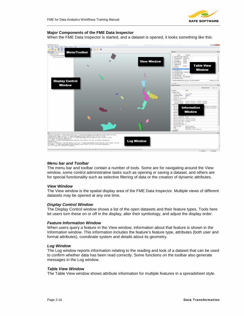
Major Components of the FME Data Inspector When the FME Data Inspector is started, and a dataset is opened, it looks something like this:
Menu bar and Toolbar The menu bar and toolbar contain a number of tools. Some are for navigating around the View window, some control administrative tasks such as opening or saving a dataset, and others are for special functionality such as selective filtering of data or the creation of dynamic attributes. View Window The View window is the spatial display area of the FME Data Inspector. Multiple views of different datasets may be opened at any one time. Display Control Window The Display Control window shows a list of the open datasets and their feature types. Tools here let users turn these on or off in the display, alter their symbology, and adjust the display order. Feature Information Window When users query a feature in the View window, information about that feature is shown in the Information window. This information includes the feature’s feature type, attributes (both user and format attributes), coordinate system and details about its geometry. Log Window The Log window reports information relating to the reading and look of a dataset that can be used to confirm whether data has been read correctly. Some functions on the toolbar also generate messages in the Log window. Table View Window The Table View window shows attribute information for multiple features in a spreadsheet style.

FME for Data Analytics Workflows Training Manual
Data Transformation Page 2-17
Using FME Data Inspector With FME Data Inspector it’s easy to open and view any number of datasets and to query features within them.
Viewing Data FME Data Inspector provides two methods for viewing data: opening or adding. Opening a Dataset Datasets can be opened in the FME Data Inspector in a number of ways.
• Selecting File > Open Dataset from the menu bar • Selecting the toolbar button Open Dataset. • Dragging and Dropping a file onto any window (except the View window) • From within Workbench
Opening data from within FME Workbench is achieved by simply right-clicking on a canvas feature type (either source or destination) and choosing the option ‘Inspect'. All of these methods cause a dialog to open in the FME Data Inspector in which to define the dataset to view. In the case of the Drag-and-Drop and Workbench Inspect methods, the dialog is automatically filled in by FME.
Adding a Dataset Opening a dataset causes a new View tab to be created and the data displayed. To open a dataset within an existing view tab requires use of tools to add a dataset.
• Selecting File > Add Dataset from the menu bar • Selecting the toolbar button Add Dataset • Dragging and Dropping a file onto the view
window

FME for Data Analytics Workflows Training Manual
Page 2-18 Data Transformation
Inspecting Data Once data has been opened in the FME Data Inspector, there are a number of tools available for altering the view or querying features. Windowing tools are:
• Pan • Zoom In • Zoom Out • Zoom to a selected feature • Zoom to the full extent of the data • Rotate/Orbit (3D data only)
Querying tools are
• Query an individual feature • Query all non-geometry features • Query with conditions
Querying a single feature updates the display in the Information window: The upper part reports on the general properties of the feature; for example which type (layer) it belongs to and which coordinate system it is in. The middle part reports the attributes associated with the feature. This includes user attributes and format attributes (for example fme_type). The lower part reports the geometry of the feature. It lists all of the individual geometries that make up the feature, and all of the coordinates that are part of those geometries. It also includes details about textures attached to features.

FME for Data Analytics Workflows Training Manual
Data Transformation Page 2-19
Table View Window The Table View window is a spreadsheet-like view of the user attributes that exist on all features on a particular feature type. Compared to the Feature Information Window it displays less information, but in a nicer way and for multiple features simultaneously.
A different tab is available for each of the Features Types open in the view window. Clicking on a tab shows the features for that Feature Type. Data for any tab can be filtered using the Filter fields just above the tab name. Like any such tool, the columns can be resized by dragging the separator bar, and data can be sorted by clicking on the column header. Right-clicking on the column header allows you to choose different methods of sorting: Additionally, the View Window is connected to the Table View, so that features queried in the View Window are highlighted in the Table View, and vice versa.
The main View Window can be made to display the Table View– rather than spatial data – by using this tool on the toolbar. To revert to a spatial view simply click on either of the two buttons to its left (the 2D/3D view buttons)

FME for Data Analytics Workflows Training Manual
Page 2-20 Data Transformation
Filtering Data The Filter button on the toolbar opens up a dialog within which conditions can be set on which spatial features to display. The dialog is similar to the Tester transformer (if you are familiar with that). It can be used to set up conditions around attributes or FME functions, and has a number of different operators such as equals (=), greater than (>), begins with, contains, etc. For example, here the user is setting up a filter to only display EMS facilities in a 911 dataset:
Here the user has set up a test using an FME Function. They are filtering the data to only display features with an area of less than 400,000 (the units being referred to will depend on what coordinate system is used).
The filtering tool is applied to ALL feature types, not just a single one.

FME for Data Analytics Workflows Training Manual
Data Transformation Page 2-21
More Data Inspector Functionality The FME Data Inspector has a number of controls to assist in showing the data in an orderly manner.
Display Control Managing the display of features is carried out in the Display Control window. Datasets and feature types are shown in the same order in the view window as they appear in the Display Control window. Each Dataset and feature type can be dragged above any other to promote its display order in the View window.
Display Status Each level of the Display Control window has a checkbox to turn data on and off at that level. Turning off a higher level in the hierarchy turns off everything below it. For example, clearing the checkbox for View 1 turns off data for the entire view. Clearing a dataset checkbox turns off data in the view for that particular dataset only. The Display Control window also gives a count of how many features there are for each View/Dataset/Feature Type. Filtering does not affect these numbers. Symbology Each feature type can be assigned a different color or style that applies to all geometries. At a lower level each separate geometry type can be assigned a different color or style.
Feature Types can only be ordered within their container Dataset. You cannot mix them up by having one feature above another dataset, with the rest of the feature types below.
Mr. R.G.B. Color says…
‘Click on the color icon:
It will open a dialog in which to change feature color. Be sure to select the Override Source option first!’

FME for Data Analytics Workflows Training Manual
Page 2-22 Data Transformation
The previous example opened its results in the FME Data Inspector. Now let’s use that application to study the results and what they contain. 1) Use Windowing Tools Use the windowing tools in the Data Inspector to zoom into the data points.
2) Query a Feature Query a feature by clicking on to it. Look in the Feature Information window to find out details about its properties, attributes, and geometry. 3) Add a Dataset To act as a reference to locate the new data, let’s add a map showing local government boundaries. Choose File > Add Dataset from the menubar (or use an alternate method such as Ctrl+D). In the Add Dataset dialog, enter the following: Reader Format MapInfo TAB (MFAL) Reader Dataset C:\FMEData\Data\GovtBoundaries\US Census Counties.zip Note that, as this is a zip file, you’ll need to change the file extension you are browsing for. Click OK to add the dataset then click the “Zoom to full extents” button to get the full picture. 4) Set Symbology If the county boundaries overlay the point features then there are two solutions. Firstly you can drag the point features above the counties in the Display Control Window.
Alternatively, you can change the drawing style of the county features by reducing the Alpha Channel value.
Example 3: Data Inspection
Scenario FME User; City of Interopolis, Planning Department
Data CSV format dataset of Cell Phone Towers, AutoCAD Map3D Object Data dataset
Overall Goal Inspect results of example 2
Demonstrates Data Inspection
Functionality: You can use the shift and control keys to switch from query mode to zoom mode, without having to use the toolbar.

FME for Data Analytics Workflows Training Manual
Data Transformation Page 2-23
5) Inspect Attributes Examine data in the Table View window. To do so, click the toolbar button to switch it into the main View Window. Notice the different tabs for the data received from Workbench and for the layer in the MapInfo TAB dataset.
Click the different tabs in turn, to inspect the attribute data for each of the Feature Types. Notice what happens when no attribute data is available. Click the CSV tab (which represents the name of the Inspector transformer added in Workbench). Click on the column header named “recorded_tstamp” to sort data in order of date. 6) Locate Features Switch back to the 2D spatial view. Click on the top record in the Table View window and see where it is highlighted on screen. This will be the feature with the oldest timestamp. Click on some features in the View Window to see them highlighted in the Table View. 7) Filter Data Click the funnel icon in the toolbar to open the dialog for filtering data. Set up a test clause that shows data from the 4th December. Then use the Negate option to show data that is not time-stamped the 4th of December.
8) Advanced Task The FME Data Inspector allows background data to be added to the display. Select Tools > FME Options from the Inspector menubar. Experiment with adding background data; either Stamen Maps or – if you have an account – ArcGIS online. Notice that you need to reopen the main datasets (or re-run the workspace) in order to view the background data.

FME for Data Analytics Workflows Training Manual
Page 2-24 Data Transformation
Data Inspection Using FME Workbench Besides ‘Redirect to Inspection Application’, Workbench can route data to FME Data Inspector from individual transformers.
Using an Inspector Transformer An Inspector is a Workbench transformer – with its own distinctive look and style – that causes data entering it to be directed to FME Data Inspector. An Inspector transformer differs from the Redirect to Inspection Application setting because the transformer can be applied at any point in a translation (not just at the very end) and does not prevent the data being output to the writer. It also lets a user be more selective about which features should be inspected.
Here data is being directed away to the Inspector after the Aggregator, but before the AreaCalculator. Note: An Inspector transformer can even be connected directly to a source Feature Type, in order to view the data immediately after it has been read by FME.
Placing an Inspector Transformer There are a number of ways to place an Inspector transformer. From the Transformer Gallery The Inspector – like any other transformer – appears in the Transformer Gallery and can be placed and connected in a workspace in the same way.
From the Menu bar An Inspector can also be placed using Insert > Inspector on the Workbench menu bar.

FME for Data Analytics Workflows Training Manual
Data Transformation Page 2-25
On the Canvas Probably the best way to apply an Inspector – and the simplest – is to right-click the output port of an object in Workbench and select the Connect Inspector option.
Copying the previous example, the user wants to output data from the Aggregator to FME Data Inspector. The user right-clicks where it says “AGGREGATE” and chooses the option Connect Inspector.
Notice how an Inspector is named automatically using the transformer and output port names. This is a big advantage of using this method.
Notice that in the FME Data Inspector > Display Control window, the feature type is named the same as the Inspector within the workspace. This helps the user to identify data when multiple Inspectors are applied.
Functionality: Note that the Inspector transformer only opens the FME Data Inspector when there are features to view. If there are zero features, then the Inspector will not open!

FME for Data Analytics Workflows Training Manual
Page 2-26 Data Transformation
Transformation Using Transformers Besides Schema Editing and Schema Mapping, transformation can be carried out using objects called Transformers.
What is a Transformer? As the name suggests, a transformer is an FME Workbench object that carries out transformation of features. A number of different transformers exist to carry out different operations. Transformers usually appear in the canvas window as rectangular, light-blue objects, although there are some transformers that vary from the norm with special shapes and colors. Transformers are connected somewhere between the source and destination feature types, so that data flows from the reader feature types, through a transformation process, and on to the writer. Transformer Parameters Each transformer may have a number of parameters – also known as settings. Access the settings by either clicking the Properties button at the top right of each transformer or by right-clicking a transformer and selecting the Properties option. Both options are shown here.

FME for Data Analytics Workflows Training Manual
Data Transformation Page 2-27
Color-Coded Properties Buttons The Properties button on a transformer is color-coded to reflect the status of the settings, described below.
A blue Properties button indicates that the default transformer settings have been checked and amended as required, and that the transformer is ready to use. A yellow Properties button indicates that the default settings have not yet been checked. The transformer can be used in this state, but the results may be unpredictable.
A red Properties button indicates that there is at least one setting for which FME cannot supply a default value. The setting must be provided with a value before the transformer can be used.
Incomplete transformers (those with a red Properties button) are also highlighted in red on the Navigator.
First-Officer Transformer says…
‘When you have a red-flagged transformer, your translation just won’t fly. You need to fix the settings before you can get off the ground.’

FME for Data Analytics Workflows Training Manual
Page 2-28 Data Transformation
Transformer Colors Transformers are all color-coded.
All regular transformers are colored blue like this AreaCalculator transformer.
Custom transformers have two different states: embedded or linked. Embedded custom transformers are colored green whereas linked custom transformers are colored cyan. Don’t worry if you don’t know what a custom transformer is yet; they’re covered later.
Some transformers, such as the Inspector, have their own distinctive icon.
Transformer Ports Far from having just a single input and/or output, a transformer can have multiple input ports, multiple output ports, or both. This Counter transformer has a single input and output port.
This Clipper has multiple input and output ports. Notice too that not all of them are – or need to be – connected.
This Terminator has just a single input port...
…whereas this Creator has only a single output port!

FME for Data Analytics Workflows Training Manual
Data Transformation Page 2-29
Content Transformation Content transformations are those that operate on the geometry or attribute content of a dataset.
What is a Feature? A feature in FME is an individual item within the translation. Typically a GIS or cartographic feature consists of a geometric representation plus a set of related attributes. FME is capable of restructuring either of these components.
Sometimes content transformation operates on single features, sometimes on multiple features at once.
Ms. Analyst says…
“You can think of Content Transformation as altering or editing data.
The wardrobe analogy still works here. You might take your clothes from the wardrobe to clean them, or alter them, or repair them, or dye them a new color, or all sorts of other tasks, before returning them to their place.
The same holds true for spatial data transformation: it’s the act of fixing up your data to be cleaner and in the style you really want”
A feature in FME is the fundamental (that is, smallest) unit of FME data. Features in FME have a flexible, generic representation; in other words they have a basic FME definition that is unrelated to the format from which they originated.

FME for Data Analytics Workflows Training Manual
Page 2-30 Data Transformation
Geometric Transformation Geometric Transformation is the act of restructuring the spatial component of an FME feature. In other words, the physical geometry of the feature undergoes some form of change to produce a different output. Some examples of geometric transformation include the following:
• Generalization – a cartographic process that restructures data so it’s easily visualized at a given map scale.
• Warping – adjustment of the size and shape of a set of features to more closely match a
set of reference data.
• Topology Computation – conversion of a set of linear features into a node/line structure.
Line Intersection is another example of geometric transformation. Here roads have been intersected with rivers to produce points that mark the location of bridges.

FME for Data Analytics Workflows Training Manual
Data Transformation Page 2-31
Attribute Transformation Attribute Transformation is the act of restructuring the non-spatial component of an FME feature. In other words, the attributes relating to the physical geometry undergo some form of change to produce a different output. Some examples of attribute transformation are:
• Concatenation – joining together of two or more attributes • Splitting – splitting one attribute into many, which is the opposite of Concatenation • Measurement – measuring a feature’s length or area to create a new attribute
• ID Creation – creating a unique ID number for a particular feature
Attribute concatenation as an example of attribute transformation. Each line of the address is concatenated to return a single line address.
Address1 Suite 2017, + Address2 7445-132nd Street, + City Surrey, + Province British Columbia, + PostalCode V3W 1J8 = Address Suite 2017, 7445-132nd Street, Surrey, British Columbia, V3W 1J8 The most common FME translation is from Esri Shape to…… Esri Shape. In other words, users are using FME for the transformation instead of the translation capabilities!
Mr. CAD says…
‘Did you know, the most common FME translation is from Esri Shape to…… Esri Shape. In other words, users are using FME for the transformation instead of the translation capabilities!
!’

FME for Data Analytics Workflows Training Manual
Page 2-32 Data Transformation
Transformers used in Series Much like a set of components in an electrical circuit, a series of Workbench Transformers can be connected together to have a cumulative effect on a set of data.
Chaining Transformers Despite the large number of transformers available in FME, users frequently find that a single transformer does not meet their requirements. In this situation, a combination or chain of transformers must be used. A string of transformers that graphically represent an overall workflow is a key concept of FME. In this example a DuplicateRemover transformer removes duplicate polygon features. A Dissolver transformer merges each remaining (unique) polygon with its neighbor where there is a common boundary. Finally each merged area gains an ID number from the Counter transformer.

FME for Data Analytics Workflows Training Manual
Data Transformation Page 2-33
Example 4: Content Transformation with Transformers
Scenario FME user; City of Interopolis, Planning Department
Data CSV format dataset of Cell Phone towers
Overall Goal Create spatial data and extract information for use in Data Analytics
Demonstrates Use of transformers in series
Starting Workspace C:\FMEData\Workspaces\DAManual\Example4Begin.fmw
Finished Workspace C:\FMEData\Workspaces\DAManual\Example4Complete.fmw
The data we are working with is now a series of point features with various attribute values that can be used for analytics. However, a typical requirement when handling sets of point features is to aggregate them spatially, into districts, in order to summarize statistics for that district. In this case there’s no existing geographical boundaries we can group against (the county boundaries we looked at earlier don’t have an even enough distribution of points) so we’ll create our own grid. 1) Start Workbench Start Workbench (if necessary) and open the workspace from Example 2. Alternatively you can open C:\FMEData\Workspaces\DAManual\Example4Begin.fmw Delete any existing Inspector transformers, as we’ll be modifying the output now. 2) Place a 2DGridAccumulator Place a 2DGridAccumulator transformer in the workspace. Remember, you can do this by clicking on a blank spot on the Canvas, and typing: 2DGrid… Once the 2DGridAccumulator is added to the Canvas, click-and-drag it towards the Reader feature type. A little pink dot will appear on the upper-left corner of the transformer when you move it. Place that pink dot over the feature type output port (or the following connector) and release the mouse button.

FME for Data Analytics Workflows Training Manual
Page 2-34 Data Transformation
3) Set 2DGridAccumulator Parameters Open the parameters dialog for the 2DGridAccumulator by clicking the red [!] button.
Set the parameters to create polygons with a column width and row height of 0.01 (remember we are using decimal degrees here). Make sure the grid type parameter is set to Polygons (not Points). Click OK to accept the parameters.
4) Run Workspace Connect Inspector transformers to the Reader feature type and 2DGridAccumulator output ports (if one is not already connected) and run the workspace. Can you see what the result of this is? We now have a grid of features that can be used to group/aggregate information for the cell towers.
It’s a common technique in FME – especially when you are new to the product – to place one or two transformers and then run the workspace; just to make sure they are doing what you expect. It’s much easier to ‘debug’ any problems when you work this way, rather than creating an entire workspace and then realizing that something is not working as expected.

FME for Data Analytics Workflows Training Manual
Data Transformation Page 2-35
Transformer Handling It’s important to know all the ways to locate, place, and connect transformers.
At this point it’s worth reviewing the different ways of handling transformers within Workbench. Transformer Gallery The transformer gallery is a window through which to locate and place transformers. Along with the Transformer Description window it plays a key part in basic transformer placement. The Transformer Gallery is divided into different sections and categories to help users find transformers. Expanding the Categorized folder displays the various categories. Expanding the All folder displays FME’s full list of transformers (400+). Another way to locate a transformer in the gallery is to type a keyword into the search field. The transformer description window provides help for the currently selected transformer. It also provides a link to articles and examples on FMEpedia. Here the Filters category of transformers is open and the AttributeFilter transformer is selected.
How to use the Transformer Gallery After a transformer is located in the gallery, it can be double-clicked it to place it on the canvas. Alternatively, it can be placed by dragging and dropping it onto the workspace canvas. Many users drag and drop transformers because that gives them greater control over where the transformer is positioned initially. When placed, users can add transformers into a workflow by dragging connections onto the transformer’s input ports and dragging connections from the transformer’s output ports. Here a SurfaceDraper transformer has been placed and connected.

FME for Data Analytics Workflows Training Manual
Page 2-36 Data Transformation
Quick Add Quick Add is a way to search for and add transformers to the workspace. This makes it easily more convenient than the Transformer Gallery for most uses. How to Use Quick Add Quick Add is a dialog on the workspace canvas that is used to search for a transformer by name. To use it, click an area of blank space on the workspace canvas and type a letter on the keyboard; for example, a. At this point a small dialog opens that looks like this.
Continue to type (for example the letter t), and a list of transformers with names that match the typed content starts to appear.
The more letters typed, the smaller the list gets until the required transformer can be located.
Pressing Enter (the return key) or clicking the transformer name causes it to be placed on the workspace canvas. Notice that it is pre-selected, so that pressing the return key again will now open the parameters dialog for the transformer.
Sister Intuitive says…
“Quick Add is one of my favorite things about FME. And notice that if you press the Tab key in Quick Add mode, you switch from a transformer name search to a transformer description search. That’s truly heavenly!”

FME for Data Analytics Workflows Training Manual
Data Transformation Page 2-37
Drag-and-Insert
Here a user wants to insert this AttributeCopier transformer into the pipeline. This functionality is activated automatically when a transformer is dragged across the canvas and shows as a small pink colored spot on the transformer’s left-hand side.
Now the user starts to drag the transformer and the pink spot appears.
Drag the transformer until the pink spot covers an existing connection. That connection becomes highlighted to indicate it is where the transformer is to be inserted.
Now the user drags the pink spot over the existing connection, which becomes highlighted.
Release the transformer to drop it into position and connect it automatically. The user releases the transformer and it is inserted into the pipeline.
Don’t forget drag-and-insert (or even drag-connect) works on any workspace object, including feature types. With this ability a feature type can be attached onto a transformer instead of the other way around
Doctor Workbench says…
“If you see pink spots, don’t worry! It’s not a disease… it’s the FME drag-and-insert functionality for speedier transformer placement!”

FME for Data Analytics Workflows Training Manual
Page 2-38 Data Transformation
Quick Connect Quick Connect is a way of making connections between transformers and feature types that does not involve dragging links between the two. All the user needs to do is click the appropriate input and output ports, and a connection is made. Hover over an output port and it is highlighted in blue.
Select the port and it is highlighted orange. The cursor also changes shape.
Hover over an input port and it now highlights blue.
Select the port and the connection is complete.
When to use Quick Connect Quick Connect is the best method to use when connecting two objects at far ends of a large workspace. Without Quick Connect the user would need to zoom out to a level at which both objects could be seen. This makes it difficult to create the connection. With Quick Connect the two objects do not need to be on screen simultaneously. A user can click on the first port (at any zoom level) and use window panning tools to move to the next port.

FME for Data Analytics Workflows Training Manual
Data Transformation Page 2-39
Combining Quick Add, Drag-Insert and Quick Connect Perhaps the best thing about these transformer shortcuts is that they are all fully integrated, so that Quick Add can be used in combination with either of the Drag-and-Insert and Quick Connect methods of placing transformers. This integration operates in a number of ways. If a connection is selected on the canvas already, when a transformer is placed using Quick Add the transformer is inserted automatically into that connection.
For example, the user first selects an existing link.
Now they select a transformer with Quick Add.
Then the new transformer is inserted directly into the chosen connection.
If a port is already selected on the canvas, the new transformer is inserted automatically or attached onto all connections on that port. Here the user has selected an existing port:
Quick Add adds the new transformer into both links emerging from the chosen port.

FME for Data Analytics Workflows Training Manual
Page 2-40 Data Transformation
If a transformer or source Feature Type is already selected on the canvas, then the new transformer is connected automatically after the existing transformer.
Using Quick Add a source Feature Type is selected while a transformer is added.
The new transformer is placed and connected to the selected Feature Type. Because the new transformer is pre-selected automatically, the user can now continue adding transformers.
The second transformer is added after the first, and so on.
Transformer Description Window As mentioned, it’s possible now to keep the Transformer Gallery closed for most of the time, and to use Quick Add functionality instead. What really makes this feasible is that the Transformer Description is split off as a separate window. Then the Transformer Gallery may be closed and the Transformer Description window retained. Additionally, the Transformer Description window shows HTML-based help for whatever transformer is selected on the workspace canvas.

FME for Data Analytics Workflows Training Manual
Data Transformation Page 2-41
Inserting Multi-Port Transformers When a transformer has only a single input and output port, FME is able to determine immediately the drag-n-insert connections to make. However, many transformers possess more than a single input or output port and, therefore, an automatic connection cannot be made. In these cases, the user is prompted to define what connections are required through a dialog. Here the transformer to be inserted is a Clipper. The Clipper has two input ports and three output ports.
When the Clipper is dropped into position, FME opens a dialog and prompts the user to select which input and output ports are to be connected.
When the user clicks OK, Workbench makes the connection as defined by the selected ports.

FME for Data Analytics Workflows Training Manual
Page 2-42 Data Transformation
Transformer Deletions FME doesn’t only provide tools for adding transformers efficiently; it also has powerful tools for removing them too. Transformers can be deleted either by selecting the transformer and pressing the <delete> key, or by right-clicking the transformer and choosing Delete. Smart Delete When a transformer is removed, FME doesn’t just leave a gap, but instead tries to reconnect the surrounding objects. This technology is called Smart Delete. When objects are automatically reconnected in this way, the connections are colored green so the user is aware of what has happened. They are also automatically selected. Therefore the user can just press <delete> for a second time to remove them. Here a user wishes to remove the Tester transformer:
They select the Tester, press the delete key and Smart Delete removes the transformer and reconnects the surrounding objects. If the user does not require the new connections they can simply press the delete key again.
To bypass the Smart Delete function, press the <shift> key while deleting an object.

FME for Data Analytics Workflows Training Manual
Data Transformation Page 2-43
Transformers used in Parallel FME Workbench permits multiple data streams, each of which passes through its own set of transformers.
Multiple Streams A key concept in FME is the ability to create multiple processing streams within a workflow or to bring several streams together into one.
Creating Multiple Streams Splitting data occurs with any transformer with multiple output ports (example 2 is a good illustration of this point) but can also be achieved by simply making multiple connections out of a single output port. When using multiple ports the data is being split amongst the different streams. However, when using multiple connections from a single port, the data is being duplicated rather than being split. In effect it creates a set of data for each connection.
Here 50 road features are being read but, because there are multiple connections from the feature type, multiple copies of the data are being created. Multiple streams are useful when a user needs to process the same data, but in a number of different ways.
Bringing Together Multiple Streams When multiple streams are brought into the same input port no merging takes place. The data is simply accumulated into a single stream.
Here three streams of 50 features each, converge upon a single AreaCalculator:INPUT port. Notice how no merging has taken place; the data simply accumulates into 150 output features. To carry out actual merging of data requires a specific transformer such as the FeatureMerger.
Similar terms to ‘stream’ are ‘flows’, ‘pipes’, or ‘pipelines’.

FME for Data Analytics Workflows Training Manual
Page 2-44 Data Transformation
Example 5: Content Transformation with Parallel Transformers
Scenario FME user; City of Interopolis, Planning Department
Data CSV format dataset of Cell Phone towers
Overall Goal Create spatial data and extract information for use in Data Analytics
Demonstrates Use of transformers in parallel
Starting Workspace C:\FMEData\Workspaces\DAManual\Example5Begin.fmw
Finished Workspace C:\FMEData\Workspaces\DAManual\Example5Complete.fmw
The previous example created a grid by which point feature data could be aggregated into areas. The next task is to transfer all of the information from the points onto their related grid square. 1) Start Workbench Start Workbench (if necessary) and open the workspace from Example 4. Alternatively you can open C:\FMEData\Workspaces\DAManual\Example5Begin.fmw Delete any existing Inspector transformers, as we’ll be modifying the output now. 2) Place a PointOnAreaOverlayer Add a PointOnAreaOverlayer transformer. This transformer carries out a spatial analysis and copies attribute data from points onto their surrounding areas. The difference this time is that we’ll connect this transformer in parallel to an existing stream. Connect the output port of the Reader feature type to the POINT input port of the PointOnAreaOverlayer. Connect the GRID output port of the 2DGridAccumulator to the AREA input port of the PointOnAreaOverlayer. 3) Set Parameters Open the PointOnAreaOverlayer parameters dialog. Enter a list name of mylist. Click OK to accept the changes.

FME for Data Analytics Workflows Training Manual
Data Transformation Page 2-45
4) Run Translation Connect Inspector transformers where you think necessary to inspect the output of this step. Run the workspace and inspect the grid features to see what the result of this action is. 5) Remove Unwanted Attributes FME translations perform faster, and produce cleaner results, when you can remove any unrequired data. In this case, the output area features have a lot of attributes. We’ll remove the ones we don’t need and keep only _column, _row, _overlaps, and list{}. You can clean up attributes with either an AttributeRemover or AttributeKeeper transformer. In this case we’ll use the AttributeKeeper as there are fewer attributes that we want to keep than we want to remove, and this transformer will be easier to use.
Place an AttributeKeeper transformer and connect it to the AREA output port of the PointOnAreaOverlayer. Open the AttributeKeeper parameters dialog. Select _column, _overlaps, and _row as the attributes to keep. Select mylist{} as the list to keep.
Terminology: A List in FME is a mechanism that allows multiple values per attribute. For example, the attribute myAttribute can only contain a single value. However, the list attribute myList{}.myAttribute can contain multiple values as: myList{0}.myAttribute myList{1}.myAttribute myList{2}.myAttribute etc.
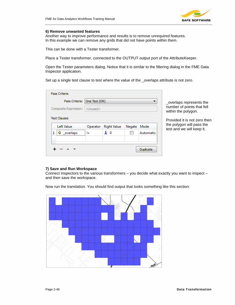
FME for Data Analytics Workflows Training Manual
Page 2-46 Data Transformation
6) Remove unwanted features Another way to improve performance and results is to remove unrequired features. In this example we can remove any grids that did not have points within them. This can be done with a Tester transformer. Place a Tester transformer, connected to the OUTPUT output port of the AttributeKeeper. Open the Tester parameters dialog. Notice that it is similar to the filtering dialog in the FME Data Inspector application. Set up a single test clause to test where the value of the _overlaps attribute is not zero.
_overlaps represents the number of points that fell within the polygon. Provided it is not zero then the polygon will pass the test and we will keep it.
7) Save and Run Workspace Connect Inspectors to the various transformers – you decide what exactly you want to inspect – and then save the workspace. Now run the translation. You should find output that looks something like this section:

FME for Data Analytics Workflows Training Manual
Data Transformation Page 2-47
Coordinate System Transformation To be located in a particular space on the Earth’s surface the majority of spatial data is related to a particular coordinate system.
Coordinate System Basics Each feature that is processed by FME is coordinate system aware; that is, it knows what coordinate system it belongs to at all times. This helps prevent confusion when reading multiple datasets that belong to different coordinate systems.
Coordinate System Settings Each source reader and destination writer within FME is assigned a coordinate system. That coordinate system is set in the navigation pane of Workbench.
Here the source coordinate system has been defined as TX83-CF and the destination as UTM83-13F. When a translation is carried out where the source and the destination coordinate systems differ in this way, FME automatically restructures the data, at the end of the translation, so that the output is in the correct location.
Automatic Detection of Coordinate Systems Some data formats are capable of containing information about the coordinate system in which they are held. Shape format is one example of this. FME can be set to detect any such information. Because the source Reader coordinate system is marked <not set>, FME will try to determine the coordinate system from the source dataset. Because the destination Writer coordinate system is marked <not set>, FME will not reproject the data. Instead FME writes the data using the same coordinate system as the source data.
Terminology: Some users call this location of data a ‘projection’, but projection is just one component of a definition within space. A true definition includes projection, datum, ellipsoid, units, and sometimes a quadrant, which together is called a ‘Coordinate System’.

FME for Data Analytics Workflows Training Manual
Page 2-48 Data Transformation
Example 6: Basic Reprojection
Scenario FME user; City of Interopolis, Planning Department
Data CSV format dataset of Cell Phone towers
Overall Goal Create spatial data and extract information for use in Data Analytics
Demonstrates Spatial Data Reprojection
Starting Workspace C:\FMEData\Workspaces\DAManual\Example6Begin.fmw
Finished Workspace C:\FMEData\Workspaces\DAManual\Example6Complete.fmw Decimal degrees are not a very good method to define the size of the grid being created. A more natural measure would be either feet or metres. Let’s reproject the data so we can do just that. 1) Start Workbench Start Workbench (if necessary) and open the workspace from Example 5. Alternatively you can open C:\FMEData\Workspaces\DAManual\Example6Begin.fmw Delete any existing Inspector transformers, as we’ll be modifying the output now. 2) Double-check Reader Coordinate System On the Navigator locate the CSV reader, and expand its list of parameters. Locate the parameter labelled ‘Coordinate System’. The original value should be LL84. If the value is not LL84, then double-click the parameter to open an editor dialog and enter the coordinate system name LL84 (or select it from the Coordinate System Gallery using the Browse button).
Remember, when a Reader’s Coordinate System parameter is defined as “<not set>” FME will automatically try to determine the correct coordinate system from the dataset itself. When the source dataset is in a format that does NOT store coordinate system information (as CSV format will not) then you MUST set this parameter when you wish to reproject data derived from this reader; otherwise FME will not know how to carry out the reprojection and an error will occur. Incidentally, there is a one-to-one relationship between Reader and coordinate system; so each Reader feature type must be the same coordinate system. This is different to a Writer – which can be more granular – and where each feature type can have its own coordinate system!

FME for Data Analytics Workflows Training Manual
Data Transformation Page 2-49
3) Add a Reprojector Transformer To have data reprojected mid-translation requires the use of a transformer; in this case we’ll use the Reprojector transformer. Add a Reprojector transformer onto the canvas. It will need to be connected after the Reader feature type, but to both the parallel outputs from that object. However, this can be easily done. Drag the transformer until the pink dot lies over the green output port arrow on the 2DPointReplacer. Then release the mouse button: Drag the Reprojector again into a clear space, and rearrange the other transformers around it. That section of the workspace will now look like this:
Open the Reprojector’s parameters dialog. The Source Coordinate System parameter can be left as Read from feature, as we already checked that the incoming data is properly tagged with its correct coordinate system Set the Destination Coordinate System to TX83-C. Click OK to accept the changes.
4) Update the 2DGridAccumulator Open the parameters dialog for the 2DGridAccumulator. Set the Column Width and Row Height to 1000 (metres) instead of 0.01 (decimal degrees). Re-run the translation. If you still have the previous view still open in the FME Data Inspector, then switch between the views to see what changes have occurred (you may need to zoom in closely to tell what has changed).

FME for Data Analytics Workflows Training Manual
Translation Components
Translation Components .................................................................................................................. 3
Key Components ..................................................................................................................................... 3 Managing Components .................................................................................................................... 7
Component Management Tools ............................................................................................................... 7 Create Workspace ................................................................................................................................... 8 Add Reader/Writer ................................................................................................................................... 9 Add Feature Types ................................................................................................................................ 10 Import Feature Types ............................................................................................................................. 15 Remove Reader/Writer .......................................................................................................................... 16 Remove Feature Types ......................................................................................................................... 16 Update Feature Types ........................................................................................................................... 17 Move Feature Types .............................................................................................................................. 17
Controlling Translations .................................................................................................................. 18 Parameters ............................................................................................................................................ 18 Top-Down Effect .................................................................................................................................... 19 Priority .................................................................................................................................................... 19 Locating Parameters .............................................................................................................................. 19
Workspace Parameters .................................................................................................................. 21 Basic Workspace Parameters ................................................................................................................ 21 Advanced Workspace Parameters ......................................................................................................... 22
Reader and Writer Parameters ...................................................................................................... 24 Reader Parameters ................................................................................................................................ 24 Writer Parameters .................................................................................................................................. 24
Feature Type Parameters .............................................................................................................. 27 Feature Type Parameters ...................................................................................................................... 27
Format Attributes ............................................................................................................................ 29 Format Attributes ................................................................................................................................... 29 FME Attributes ....................................................................................................................................... 30 Controlling Features with Format Attributes ........................................................................................... 31
Data Merging .................................................................................................................................. 38 FeatureMerger ....................................................................................................................................... 38
Parameter Documentation ............................................................................................................. 41 FME Readers and Writers Reference Manual ....................................................................................... 41 Reader/Writer Parameters ..................................................................................................................... 41 Feature Type Parameters ...................................................................................................................... 42 Format Attributes ................................................................................................................................... 42
Published Parameters .................................................................................................................... 43 Publishing Parameters ........................................................................................................................... 44 Using Published Parameters ................................................................................................................. 46
Conditional Actions ......................................................................................................................... 49 Conditional Filtering ............................................................................................................................... 49 Conditional Mapping .............................................................................................................................. 49

FME for Data Analytics Workflows Training Manual
Page 3-2 Format Translations

FME for Data Analytics Workflows Training Manual
Format Translations Page 3-3
Translation Components An FME translation is made up of a number of different components.
There are many different components that go to make up a translation. For each component there are tools within FME to create, add, or remove them; and parameters in Workbench in order to control them. In particular, each component has very specific terminology applied to it, and it’s useful to have a full understanding of this terminology, especially when working with multiple datasets. Key Components The list of key components in an FME translation is as follows:
• Workspace • Readers and Writers • Feature Types • Features
It’s important to notice that all these components exist in a related hierarchy. Hierarchy is an important concept because it affects how components are added to a translation, and – more importantly – parameters at one level of the hierarchy can affect components at a different level.
This section covers “official” FME components only. For example, it won’t cover any user-defined Python scripting that might be used to exert control over several workspaces. However, it’s easy to look at this hierarchy diagram and imagine where such custom components might fit it.

FME for Data Analytics Workflows Training Manual
Page 3-4 Format Translations
Workspace A workspace is the primary element in an FME translation and is responsible for storing a translation definition. A workspace is held as a file with an .fmw file extension. It can be run in either the Quick Translator or FME Workbench, but can only be opened for editing in Workbench. Think of a workspace as the container for all the functionality of a translation. Readers and Writers A Reader is the FME term for the component in a translation that reads a source dataset. Likewise, a Writer is the component that writes to a destination dataset. Each reader and writer in a workspace handles just a single format of data. To read or write multiple formats requires the use of multiple readers and/or writers.
Readers and writers don’t appear as objects on the Workbench canvas, but are represented by entries in the Navigator window. Each reader and writer appears as a separate entry in the list. Each item in the Navigator window is represented by an icon. The icons for readers and writers look like this:
The format of each reader and writer is denoted by the format keyword. In this example the reader format is SQL Server Spatial, and the writer format is PostGIS. The “MySourceData” and “MyDestinationData” parts of the screenshot are the names of the datasets being read/written. When multiple datasets are read they are all listed, like in this AutoCAD reader.

FME for Data Analytics Workflows Training Manual
Format Translations Page 3-5
Feature Types Feature Type is the FME term that describes an identifiable subset of records. Common alternatives for this term are ‘layer’, ‘table’, ‘feature class’, and ‘object class’. A Feature Type as a translation component is simply a defined layer in the process. If a specific layer is not defined by a feature type, then that data will not be either read and/or written. Feature Types are represented by objects in the Workbench canvas, so it is easy to see at a glance which layers are represented, and where they are connected to in the translation.
In this workspace, feature types represent layers of source data called Buildings, Rail, Rivers, Roads, and Schools. The workspace canvas contains a different object for each feature type in both reader and writer.
Beside canvas objects, feature types can be found listed in the Navigator window. They are the only component to be listed in two places in this way. This is because each feature type is always associated with a Reader/Writer A writer feature type icon looks like this:
Features Features are the smallest single components of an FME translation. They aren’t individually represented within a workspace, except by the feature counts on a completed translation. Here 2,186 road features were translated.
Don’t confuse the term ‘Feature Type’ with ‘Geometry Type’. Feature Type means “layer”; Geometry Type means “lines”, “points”, “polygons”.

FME for Data Analytics Workflows Training Manual
Page 3-6 Format Translations
One-To-Many Relationships The hierarchical relationship between workspace, readers, writers, feature types, and features is always one-to-many (1:M) with the level beneath:
Notice how a single workspace can contain any number of readers and writers, each reader can contain a number of feature types, and each feature type can contain any number of features within it.

FME for Data Analytics Workflows Training Manual
Format Translations Page 3-7
Managing Components There are a number of tools for creating or adding components to a translation.
Component Management Tools All of the tools for managing components (creating, adding, or deleting) in a translation can be found on the FME Workbench menubar, as well as in some context-menus.

FME for Data Analytics Workflows Training Manual
Page 3-8 Format Translations
The list of tools for managing components in an FME translation is as follows:
• Create Workspace • Add Reader/Writer • Add Feature Types • Import Feature Types • Remove Reader/Writer • Remove Feature Types • Update Feature Types • Move Feature Types
Create Workspace The most common way to start creating a translation definition is to create a workspace through one of the tools in FME Workbench. File > New on the menubar opens up the Create Workspace dialog and provides a list of methods for creating a new workspace, or even starting out with a template workspace from an online source. Creating a workspace through the Generate options is a simple way to define a translation because it includes reader, writer and feature type components in the setup process.

FME for Data Analytics Workflows Training Manual
Format Translations Page 3-9
Add Reader/Writer Adding a reader or writer to a workspace is a common requirement. There are several reasons:
• The Generate Workspace dialog only adds a single Reader and Writer
• Each Reader and Writer handles only one
format of data.
• Different datasets (of the same format) may require handling with different parameters
Therefore handling multiple formats of data – such as a workspace that reads Smallworld, DXF, and Geodatabase; and writes to both Oracle and a text file – requires multiple readers/writers.
Additional readers are added to a translation using Readers > Add Reader from the menubar. Similarly, additional writers are added using Writers > Add Writer
Adding a reader has this effect on the hierarchy diagram: Be aware that adding Readers and Writers can also add Feature Types to the workspace too, as is explained in the next section.

FME for Data Analytics Workflows Training Manual
Page 3-10 Format Translations
Add Feature Types Adding feature types can take place either when adding a reader/writer, or by a manual process. In general, manually adding a feature type is only permitted on the writer side of a translation. That’s because the writer side is “What We Want” and is therefore open to manual editing. Adding a feature type manually has this effect on the hierarchy diagram.
Adding Feature Types with a Reader When adding a reader, FME will scan the chosen source data and prompt the user as to which source feature types should be added to the workspace.
Each chosen type – and not all have to be selected – will be represented by a feature type object below the new Reader.

FME for Data Analytics Workflows Training Manual
Format Translations Page 3-11
Adding Feature Types with a Writer When adding a writer, FME will offer a chance to manually add a new feature type.
Responding yes to this question opens up the dialog for manually defining a new feature type. Only one feature type can be added at this time. Additional ones must be added manually. No is the correct response when feature types are to be copied from a reader (see below) or imported from a different dataset (see next section). Adding Manually Feature Types can be added manually to a writer using Writers > Add Feature Type on the menubar.
Note that at least one writer must exist in the translation hierarchy; else this option will be greyed out.
Choosing to add a feature type adds one to the translation, and then causes the Feature Type Properties dialog to appear in order to edit the feature type properties. The General tab can be used to define the new feature type’s name The User Attributes tab can be used to define the new Feature Type’s attribute schema

FME for Data Analytics Workflows Training Manual
Page 3-12 Format Translations
Copying from a Reader In some cases a user will have a reader with multiple feature types, and wish to add the same ones to a writer. This is simply done by selecting the source feature types, right-clicking them, and using the option Duplicate (on Writer).
The command causes duplicates of the feature types to be added to the writer, and source/destination feature types to be automatically connected. Again, at least one writer must exist in the translation hierarchy; else this option will be greyed out.
In the hierarchy diagram, copying feature types looks like this:

FME for Data Analytics Workflows Training Manual
Format Translations Page 3-13
Demonstrates Writing Data
Starting Workspace C:\FMEData\Workspaces\DAManual\Example7Begin.fmw
Finished Workspace C:\FMEData\Workspaces\DAManual\Example7Complete.fmw Now we’ve read and processed the data, the natural progression is to write it to an output dataset. 1) Start Workbench Start Workbench (if necessary) and open the workspace from Example 6. Alternatively you can open C:\FMEData\Workspaces\DAManual\Example7Begin.fmw Delete any existing Inspector transformers, as we’ll be modifying the output now. 2) Add a Writer Add a writer by selecting Writers > Add Writer from the menubar. In the Add Writer dialog the following options: Writer Format MapInfo TAB (MFAL) Writer Dataset C:\FMEData\Output\DAOutput There are no parameters for the MapInfo writer, so that button will remain inactive. When prompted to add a new Feature Type, click No. A Feature Type is needed, but we will define one another way.
It may seem that nothing has happened – because there is no new content on the canvas – but a writer has been added and can be seen in the Navigator window.
Example 7: Writing to MapInfo
Scenario FME user; City of Interopolis, Planning Department
Data CSV format dataset of Cell Phone towers
Overall Goal Create spatial data and extract information for use in Data Analytics

FME for Data Analytics Workflows Training Manual
Page 3-14 Format Translations
3) Define Feature Type We’ll define a Feature Type on the writer that is a copy of the reader one. Right-click the CSV Reader Feature Type and choose Duplicate (on Writer). The source feature type will be duplicated on the writer and automatically connected.
However, we don’t require a connection from the source, but from the Tester transformer, so delete any connection made to the Writer Feature Type, and connect it to the Tester PASSED output port.
4) Run translation Save the workspace and then run the translation. Open the output dataset in the FME Data Inspector to examine the contents. Notice that any attributes with have a value of -9999. This is the default MapInfo value for an empty attribute. All attributes are empty because we’ve turned them into a list, but haven’t yet updated the schema to match.

FME for Data Analytics Workflows Training Manual
Format Translations Page 3-15
Import Feature Types To understand importing feature types, it’s important to recognize that “schema” is a separate entity, capable of being used and copied independently of any actions on the data itself. What the import tool does is essentially take a dataset’s schema, and add it to a workspace. For example, a user has a workspace reading from a spatial database. It only needs to read from a single table (roads), so there is a single Reader representing the database, and a single Feature Type representing the table. However, at some future point the user decides the workspace also needs to read from a second table (‘rail’).
The simplest solution is to use the command Readers > Import Feature Types…
The import tool will take the schema definition of the database table ‘rail’ and add it to the workspace. This is particularly important for a reader, because there is no “Add Feature Type” tool for a reader; the reason being that a source schema represents “What We Have” and adding user-defined definitions doesn’t reflect that reality. Interestingly, the import tool can import schemas from a dataset without that dataset being part of the actual translation. Even a different format is no impediment to using a schema this way. For example, a user may wish to store table definitions in XML, importing feature types from the XML schema for use in writing to another format. A Spatial Data Infrastructure (SDI) with a rigidly defined schema, but open format specification, might be one use of this scenario.
It’s always preferable to import feature types, or copy them from an existing Reader, rather than manually add them. That’s because a manual process is slower and more prone to user error; especially when case sensitivity is an issue.

FME for Data Analytics Workflows Training Manual
Page 3-16 Format Translations
Remove Reader/Writer Tools exist to remove a reader or writer from a workspace, both on the menubar and in context menus in the Navigator window.
Note that whenever a reader or writer is removed, then all the related feature types will also be removed.
Remove Feature Types This remove feature types function works at a lower level of the hierarchy than reader/writer removal, and just removes one or more feature types from the translation. There is a menubar tool, but the easier method is to select the feature type(s) in the canvas and simply press the delete key on the keyboard. Whenever all feature types are deleted from a Reader or Writer then FME will prompt the user to decide whether to remove the Reader/Writer as well.
If the feature types are all removed, and yet the Reader or Writer is left in the translation, then the hierarchy diagram has a “dangling” Reader/Writer.
A dangling reader/writer isn’t a problem provided it’s only a temporary situation; i.e. the user intends to now import or add new feature types. The workspace should not be run in this condition! Performance suffers because all the source data is still being read. With a dangling reader it is discarded immediately, but with a dangling writer it is read and transformed too.

FME for Data Analytics Workflows Training Manual
Format Translations Page 3-17
Update Feature Types A frequent problem occurs when – after setting up a workspace – the structure of the source data changes; for example, a new attribute is added or the data type of an existing attribute is changed. Because feature type definitions in Workbench can be adversely affected by underlying data changes, FME provides a way to update a workspace based on a new data structure. Readers > Update Feature Types and Writers > Update Feature Types are the tools available to do this. Both are a little like the Import Feature Type tool, except that the external schema is used to update a translation component of the same name, rather than to add a new one.
Move Feature Types As previously noted, a schema can be considered an independent object capable of being used for any reader/writer. This means there is no reason why feature types can’t be moved from one writer to another, as and when required. Whenever there are two or more writers, the Dataset setting in the writer Feature Type properties becomes active. By changing this, the feature type is moved from one writer to another.
Moving a feature type is not a common procedure, but it’s a very useful time-saver when necessary.
Use caution here – especially with CSV and Excel datasets. If you update a Reader/Writer using different parameters, then problems can occur when the translation is run. The safest solution is to delete the Reader/Writer and replace it with a new one.

FME for Data Analytics Workflows Training Manual
Page 3-18 Format Translations
Controlling Translations
Successfully translating from one format to another requires a firm grasp on all the parameters that control the translation.
Parameters are what control a translation.
In the hierarchy of different translation components, each different level of the hierarchy has a set of parameters that belong to it. So there are:
• Workspace Parameters • Reader Parameters • Writer Parameters • Feature Type Parameters • Format Attributes (Feature Parameters)
Having parameters right down to the feature level provides a huge degree of control over every aspect of a translation.
Chef Bimm says…
“Parameters in a translation are like the options when you order a coffee.
You get to choose what ingredients you start with, how they are combined, and what the end result of the process will be like. For example, the parameters in my coffee are decaf, grandé, extra-hot, no-whip, 2%, half-sweet, gingerbread latté! I always was very demanding.”

FME for Data Analytics Workflows Training Manual
Format Translations Page 3-19
Top-Down Effect The basic rule is that any higher-level parameter affects every component below it. For example, a Workspace Parameter affects all Readers and Writers, all Feature Types that belong to those Readers/Writers, and all features that belong to the Feature Types. A Reader Parameter affects all Feature Types that belong to that particular reader, but not Feature Types belonging to another Reader.
Priority Priority is important because, in some cases, the same parameter exists at different levels. Perhaps the best example of this is database writing mode. Database writing mode (Insert, Update, or Delete) can be set firstly at the Writer level, in which case it applies to all tables and features. For example, if the writer level is set to INSERT then ALL features are written to tables as an insert. But database writing mode can also be set at the Feature Type level, in which case it applies only to features written to that table. This allows different tables to have different modes. Finally, database writing mode can be set on individual features. Different features can be used to insert, update, or delete records – simultaneously – in the same table. Interestingly, the higher-up parameter only applies when the lower-down parameters are not set. When the same parameter is set at different levels, then the lower-level parameter wins out. For example, a Writer might be set as INSERT mode; but a table is set to UPDATE mode. In that case the feature type level parameter wins out, and features are written to that table as an update.
To carry on Chef Bimm’s analogy, if you load a coffee machine with Decaffeinated coffee, then all of the drinks will be decaffeinated (Workspace Parameter).
But, each drink can still separately include cream and sugar (Feature Type Parameter)
Again it may help to return to the coffee maker analogy.
The coffee machine may have a temperature option to set the temperature of drinks. This parameter (being at the top level) will apply to all drinks.
However, there may also be a temperature override button as a drink is prepared. Therefore, although the same temperature option occurs at each level, the lower level parameter takes priority (i.e. it overrides the higher-up parameter).

FME for Data Analytics Workflows Training Manual
Page 3-20 Format Translations
Locating Parameters This diagram shows where the parameters are located for each translation component. Feature Types are interesting because their parameters are found in both the Navigator Window and the Feature Type Properties dialogs.
Parameter Location Workspace Parameters Navigator Window Reader and Writer Parameters Navigator Window Feature Type Parameters Navigator Window and Feature Type Properties dialog Format Attributes Feature Type Properties dialog As will be shown, although parameters to control features are exposed in the Feature Type Properties dialog, they are usually set using a transformer.

FME for Data Analytics Workflows Training Manual
Format Translations Page 3-21
Workspace Parameters Workspace parameters relate to the workspace as a whole.
Workspace parameters (settings) are all of the parameters that relate to a workspace as a whole. They apply to the current workspace only and may change between workspaces. Workspace parameters are shown and set in the Navigator Window.
The Workspace Parameters section contains settings that have an effect on how the translation is performed. Settings that provide information about a workspace such as Workspace Name and Workspace Description, but have no effect on the translation, are found in the Workspace Properties section. For ease-of-use, workspace parameters are divided into two sections: basic and advanced.
Don’t confuse Workspace Parameters with another set of Navigator items called Workspace Properties. Workspace Properties are a set of metadata fields, including Workspace Name and Workspace Description, and have no direct effect on how a translation is carried out.

FME for Data Analytics Workflows Training Manual
Page 3-22 Format Translations
Basic Workspace Parameters There are a number of basic workspace parameters. The most important one is Destination Redirect. Destination Redirect The Destination Redirect parameter overrides the Writer defined in the workspace. It causes FME to send the translation output elsewhere and no data is written to the destination datasets. To write output again the user must remove the redirect by choosing the No Redirect setting.
The destination redirect options are: Redirect to Inspection Application: Output is sent directly to the FME Data Inspector. Redirect to FFS File: Output is sent to an FFS (FME Feature Store) file. Disable Output: Output is ignored and not used (similar to a NULL format writer).
‘Redirect to Inspection Application’ can also be found on the menu bar, under the Writers menu.

FME for Data Analytics Workflows Training Manual
Format Translations Page 3-23
Advanced Workspace Parameters The advanced workspace parameters are perhaps not as valuable in everyday use, but have great importance in specific scenarios. Some particularly important ones are: Ignore Failed Readers This YES/NO parameter tells FME whether to continue a translation when reading a dataset fails. For example, if the wrong password is entered so that FME cannot read from a database, should the translation continue with any other datasets that FME was able to read from? Reprojection Engine Different GIS applications have slightly different algorithms for reprojecting data between different coordinate systems. To ensure that the data FME writes matches exactly to existing data, this parameter permits a user to use the reprojection engine from a different application.
A user with ArcGIS installed is choosing to use that package’s engine for reprojecting the spatial data.
Password It‘s often desirable to pass a workspace to an FME user for them to run, but not to edit. A password-protected workspace cannot be opened for editing in Workbench without the password. It can, however, still be run within the FME Universal Translator or from the command line. Also, developers or consultants may want to pass on a workspace to an FME user without revealing the contents. Password protecting a workspace causes it to be encoded so that its contents cannot be read in a standard text editor. Check for Missing Attribute References This parameter determines what happens when an attribute used to supply a value is deleted or otherwise removed, so that it becomes unavailable. In most cases the workspace user will wish to be alerted to this problem, so the default for this parameter is “Yes”. However, in some cases – for example as can occur in an older workspace – the attribute is not really “missing” but just invisible to FME. In this scenario, where the author is certain that such attributes do exist, then he/she may set this parameter to “No” to avoid unwanted error messages. Start-up and Shutdown Scripts These parameters deliver the ability to run a TCL or Python script before or after an FME translation. Script parameters in the workspace settings dialog: Potential uses of such scripts include:
• To check a database connection before running the translation
• To move data prior to or after the translation • To write the translation results to a custom log or send them as e-mail to an administrator • To run scripts from other applications; for example Esri ArcObjects Python scripts

FME for Data Analytics Workflows Training Manual
Page 3-24 Format Translations
Reader and Writer Parameters Each reader or writer added to a workspace is controlled by a number of settings and parameters that are available.
Reader and Writer parameters are those that control how data is read and written. Because these parameters refer to specific components and characteristics of the related format, no two formats will have the same set of control parameters. Also, because different parameters may be required, even the reader and writer of a single format may have different sets of parameters. For ease-of-use, parameters are divided into two sections: basic and advanced. Reader Parameters Reader parameters are shown and set in the Navigator Window. To edit a parameter, double-click it. A dialog opens up where the parameter’s value may be set.
Doctor Workbench says…
‘Some Reader (and Writer) parameters are ONLY accessible through the Parameters button when you initially create a workspace or add the Reader/Writer to an existing workspace. That’s because they affect how the schema is read and therefore how the workspace is constructed. It’s like preparing a patient for surgery. Once the workspace (patient) is created (prepped) those parameters aren’t available because you’re past the point where they would have any effect. Of course, sometimes you get such a parameter wrong, in which case you simply recreate the workspace. Or find yourself a new patient!

FME for Data Analytics Workflows Training Manual
Format Translations Page 3-25
Writer Parameters Writer parameters are shown and set in the Navigator Window. To edit a parameter, double-click it. A dialog opens up where the parameter’s value may be set.
Parameter Priority It’s worth emphasizing that, because Readers and Writers are at a relatively high level in the translation hierarchy, their parameters apply to everything beneath them; that is, ALL features types and ALL features. Database Password is a good example of a Reader/Writer-level parameter. A database user password is something that applies to ALL tables being read. There isn’t a different password per table! Therefore it is a Reader/Writer level parameter.

FME for Data Analytics Workflows Training Manual
Page 3-26 Format Translations
Demonstrates Previewing Data
Starting Workspace C:\FMEData\Workspaces\DAManual\Example8Begin.fmw
Finished Workspace C:\FMEData\Workspaces\DAManual\Example8Complete.fmw
Sometimes it’s better to run a workspace without writing any output – for example when you are testing a workspace and don’t want to overwrite existing data (particularly in a database). FME allows you to do this by automatically redirecting the output elsewhere. 1) Start Workbench Start Workbench (if necessary) and open the workspace from Example 7. Alternatively you can open C:\FMEData\Workspaces\DAManual\Example8Begin.fmw 2) Redirect to Inspector In the Navigator window, locate and check the workspace parameter ‘Destination Redirect’. At the moment it will be set to ‘No Redirect’. Changing this setting to ‘Redirect to Inspection Application’ is the equivalent to using Writers > Redirect to Inspection Application. In fact, you can try this to show how changing one automatically affects the other. Changing the Destination Redirect setting to ‘Disable Output’ prevents writing any data to the destination dataset or to FME Data Inspector. In effect, you’re running the workspace up until the writers take effect, testing the reading and transformation steps of the translation. Experiment with setting the Destination Redirect option to either Redirect to Inspection Application or Disable Output, and running the workspace. Do you notice anything about what attributes exist compared to inspecting the actual output dataset?
Example 8: Data Previews
Scenario FME user; City of Interopolis, Planning Department
Data CSV format dataset of Cell Phone towers
Overall Goal Create spatial data and extract information for use in Data Analytics
Notice that disabling the output or redirecting it to the Data Inspector, does not remove any existing output dataset. i.e. if you have already written the data, running the workspace again with disabled output will NOT remove the output from the previous run. In short, FME will never delete a dataset unless it is overwriting that file.

FME for Data Analytics Workflows Training Manual
Format Translations Page 3-27
Feature Type Parameters Each reader or writer added to a workspace is controlled by a number of settings and parameters that are available.
Feature Type Parameters Feature Types are at a lower level in the hierarchy than readers and writers. Therefore, Feature Type parameters don’t apply to datasets as a whole, but only to individual feature types within a dataset. They provide a degree of individual control over reading and writing different layers or tables. Reader Feature Type Parameters Reader feature type parameters apply to reading of specific layers/tables. A general rule is that database formats have reader feature type parameters, but few file-based formats do.
Feature Type Parameters can also be accessed through the Feature Type Properties dialog. Notice the tab named Format Parameters. Not all feature types have parameters, so this tab is not always present.

FME for Data Analytics Workflows Training Manual
Page 3-28 Format Translations
Writer Feature Type Parameters Writer feature type parameters apply to writing of specific layers/tables. Again, most database formats have writer feature type parameters, but a high proportion of file-based formats also have these.
Create Spatial Index is a good example of a feature type parameter. The decision about whether or not to apply an index is made on a table-by-table basis. Not all tables may require an index. There can be a different index per table. Therefore this is a feature type parameter. If it were a writer-level parameter, then ALL tables would get an index; not necessarily what the user wants. Conversely, no password parameter is listed because it applies to the entire database, not the individual tables.

FME for Data Analytics Workflows Training Manual
Format Translations Page 3-29
Format Attributes Besides ‘user attributes’ there is a whole range of attributes created by FME: Format Attributes
Although features are the lowest level in the hierarchy of translation components, it’s very useful to be able to control and manipulate individual features. However, control of features isn’t done using parameters, but instead with a constituent part of features called Format Attributes. Format Attributes A format attribute is a built-in, FME-generated attribute. It represents part of the structure of a feature for any given format; i.e. information that isn’t generally carried as part of the geometry or as a user attribute. The color of a feature is one example of information held by format attributes. FME uses these format attributes to keep track of such information and make sure it is passed on correctly to a destination dataset. Format attributes are most obvious when viewing a dataset with FME Data Inspector. Querying a feature causes both user attributes and format attributes to be reported. For example, inspecting AutoCAD Map3D Object data in the FME Data Inspector will show many format attributes, such as:
• autocad_color: Color of the feature • autocad_entity: Type of geometry • autocad_od_entity_key: Object Data ID • autocad_source_filename: Source file
Other features, such as a point geometry, might have a format attribute to record rotation, while an arc feature would have format attributes to record arc length and angle. Notice how the attribute name starts with a format keyword, to differentiate the same format attributes for different formats of data.

FME for Data Analytics Workflows Training Manual
Page 3-30 Format Translations
FME Attributes A particular set of Format Attributes has the prefix fme_. These attributes represent the data as it is perceived by FME and are sometimes known as FME Attributes or Generic FME Attributes. When a translation is carried out, the following occurs:
• FME reads the source data and stores information about its features as format attributes. These format attributes reflect the data that is stored in the original source data.
• FME converts the source data’s format attributes into FME Attributes. These FME attributes reflect the source data as it is perceived within FME.
• FME writes the destination data by creating a new set of format attributes. These format attributes reflect the information as it will be stored in the destination data.
This is why, when a user inspects data, there are two sets of attributes. In the previous screenshot were both autocad_color and fme_color; the latter is the FME representation of the former. Using this method, FME can convert from one format to another, without having to separately map the source format attributes to the destination format attributes for every format. FME merely converts everything to an FME standard and then from there to the Writer Format.
Reading Writing
Format Attribute FME Attribute Format Attribute
Source Data Within FME Destination Data
Reading Writing
igds_color 3
fme_color 1,0,0
kml_linestyle_color ff0000ff
Source Data Within FME Destination Data

FME for Data Analytics Workflows Training Manual
Format Translations Page 3-31
Controlling Features with Format Attributes A user can make use of these attributes to carry out certain tasks by making the attributes part of the workspace. As mentioned, a user doesn’t have direct control over features with parameters, but instead uses format attributes. However, to avoid cluttering the workspace these attributes are not all visible by default. To make them visible is known as “exposing” them, and involves the Feature Types Properties dialog. Exposing Format Attributes To expose a format attribute, open the Feature Type Properties dialog, and click the ‘Format Attributes’ tab. Locate the Format Attribute to expose and check the box provided. Click OK to make the format attribute available for use within Workbench.
Format attributes might be a single attribute (for example, igds_style) or they might be a list-based format attribute, for example (igds_tag_names{})
Firefighter Mapp says…
‘An alternate method is to use the AttributeExposer transformer.’

FME for Data Analytics Workflows Training Manual
Page 3-32 Format Translations
Filtering with Format Attributes One primary use of format attributes is as a means of filtering and directing source data within a workspace. For example, suppose features in a source AutoCAD dataset are not divided into different layers as they should be. Because the user is able to determine the proper layer from maybe the color of the feature or the size of a text entity, they can expose the format attributes autocad_color or autocad_text_size, and use them to interpret the correct layer. Most “filter” transformers (described in more detail in Chapter 6) can be used to process data in this way. List Format Attributes A List attribute is an FME structure that allows multiple values for each attribute. For example, an area of forestry might have a list of tree types (Pine, Oak, Cedar) in which case a list attribute in FME might be something like: parcelList.treeType{0} = Pine, parcelList.treeType{1} = Oak, parcelList.treeType{2} = Cedar This is important here because some format attributes can also be a list type of attribute. In this example, the user has exposed the list format attribute igds_tag_names{} When they attempt to use that attribute in a Tester transformer, they are prompted to choose which element in the list is to be tested. Because transformer dialogs ask which element in a list is to be used, it’s not necessary to have to expose multiple elements solely to get access to a single one.

FME for Data Analytics Workflows Training Manual
Format Translations Page 3-33
Transforming with Format Attributes The other primary use of format attributes is to transform the data itself. When writing data, FME attributes are turned into format attributes that reflect the data as it’s supposed to be written. However, a user can override this process by predefining the value of these attributes before they are sent to the writer. In other words, setting a format attribute may cause a transformation in the data to take place. Either the writer format attribute (here kml_linestyle_color) or the equivalent FME attribute (here fme_color) may be set to achieve the same end. A user can define either attribute because if fme_color is set it is converted to kml_linestyle_color as normal, and if kml_linestyle_color is set then FME knows not to over- write it. If a user manages to define both a format attribute and its FME equivalent, then the format attribute takes precedence and is used. For example, set fme_color and kml_linestyle_color, and the kml attribute gets priority. This only really becomes a problem when reading and writing the same format, and the same format attributes exists on both reader and writer. In that case use the format attribute; it’s not safe to use the FME equivalents.
Transformation
User-Defined
Reading Writing
igds_color 3
fme_color 1,0,0
kml_linestyle_color ffff7f3f
Source Data Within FME Destination Data
fme_color 0.25,0.5,1.0

FME for Data Analytics Workflows Training Manual
Page 3-34 Format Translations
Transformers for Setting Format Attributes Format Attributes can actually be a little tricky to set. Once a format attribute is exposed on a reader feature type, then an AttributeCreator transformer can be used to change its value. But this won’t have any effect unless the translation is reading and writing from the same format. On the other hand, exposing a format attribute on a writer feature type doesn’t make that attribute available in the workspace in the same way (i.e. it isn’t exposed back upstream). So, the most common method is to use the AttributeCreator transformer, but actually create the writer attribute and set it; for example create autocad_block_name and set a value for it.
The other common method is to use a constant, where format attributes exposed on a destination can be set by right-clicking the attribute and choosing ‘Set to Constant Value’. Used this way, the action is more like a Feature Type parameter; that is, it applies to all features written to that feature type.
Besides setting format attributes manually like this, there are a number of FME transformers that are designed to be merely a more user-friendly front end to setting a format attribute.
The FeatureColorSetter (for example) “Assigns color to incoming features”, but in reality all it does is set a new value for the format attributes fme_color, fme_fill_color, etc.
The DGNStyler helps a user to define the symbology of features to be written to a MicroStation Design File. It is really just a more pleasant way of using format attributes. Similar transformers are:
• DWGStyler • KMLPropertySetter • KMLStyler • MapInfoStyler • PDFStyler

FME for Data Analytics Workflows Training Manual
Format Translations Page 3-35
Now it’s time to start processing the attributes to be analyzed. In this example, we will clean up the attributes, concatenate some values, and average others. Of course, we will use Format Attributes and Lists as part of this example, to demonstrate their use. 1) Start Workbench Start Workbench (if necessary) and open the workspace from either Example 7 or Example 8. Alternatively you can open C:\FMEData\Workspaces\DAManual\Example9Begin.fmw Turn off the Destination Redirect setting, if you still have it applied. 2) Concatenate Attributes Firstly we’ll create an attribute that concatenates all the Station IDs of points that overlapped with a particular grid square. We can do this with a transformer called the ListConcatenator. Add a ListConcatenator transformer between the Tester PASSED output port and the writer Feature Type. Open the parameters dialog. Select mylist{}.StationID as the List Attribute to concatenate. Set a comma character (,) as the Separator Character. Set the Destination Attribute as StationIDs
Example 9: Calculate Statistical Information
Scenario FME user; City of Interopolis, Planning Department
Data CSV format dataset of Cell Phone towers
Overall Goal Create spatial data and extract information for use in Data Analytics
Demonstrates Transformation, List Attributes, Best Practice
Starting Workspace C:\FMEData\Workspaces\DAManual\Example9Begin.fmw
Finished Workspace C:\FMEData\Workspaces\DAManual\Example9Complete.fmw

FME for Data Analytics Workflows Training Manual
Page 3-36 Format Translations
3) Concatenate Attributes - 2 Repeat step 2, but this time concatenate list{}.num_measures into an attribute called MeasureCount. NB: Ctrl+D is a good shortcut for duplicating the existing ListConcatenator. 4) Tidy Workspace Now let’s tidy up the workspace in accord with the principles of FME Best Practice.
Open a transformer’s parameter dialogs and you will see that the name of the transformer can be changed. This allows it to be more descriptive of the actual task being carried out. Open each ListConcatenator parameters dialog in turn. Rename them to:
• Concatenate Station IDs • Concatenate Measures
Now select both ListConcatenator transformers on the canvas simultaneously. Right-click them and choose the option to “Create Bookmark”. A bookmark, like its real-world namesake, is a means of putting a marker down for easy access. With FME the bookmark covers an area of workspace that is usually carrying out a specific task, so a user can pick it out of a larger set of transformers and move to it with relative ease. Set a name for the bookmark (e.g. Concatenators). That part of the workspace will now look something like this:
FME Best Practice says that a good style of design makes it easier to navigate and understand an existing workspace, and thus simplifies the editing process; much the same way as a computer programmer adding comments to explain his actions This is useful because workspaces are rarely static or used repeatedly without being edited; sooner or later the source or destination schema will change, or edits will be needed to take advantage of new or updated FME functionality. At that point a clear layout will be invaluable!

FME for Data Analytics Workflows Training Manual
Format Translations Page 3-37
5) Calculate Averages To find the average power and quality for each grid square, it’s easier to calculate this using the points themselves – so we aren’t dealing with a list. As long as we have the grid ID attached to each point (the PointOnAreaOverlayer already gives us this) then there is no problem. Place a StatisticsCalculator into the workspace. Attach it to the POINT output port on the PointOnAreaOverlayer transformer.
6) Set Parameters Open the parameters dialog for the StatisticsCalculator. For the Group-By parameter, select the attributes _column and _row This will create a group-by, where each calculation is carried out uniquely for each grid square. For the Attributes to Analyze parameter, select the attributes Power and Quality. For the remaining parameters, removing the attribute name will stop that value being calculated. Because we don’t need them, remove the attributes for: _median _count _numeric_count _range _stdev _mode Leave other parameters as they are. Click OK to close the dialog. 7) Run the Workspace Connect an Inspector transformer to the StatisticsCalculator COMPLETE output port. Save the workspace and then run it. The output point features will display a set of statistics related to all points in that particular grid square. If the max, mean, min and sum values are all equal, then don’t worry. It just means you have selected a tower that is the only one in its grid!

FME for Data Analytics Workflows Training Manual
Page 3-38 Format Translations
Data Merging The ability to merge and join records is an important skill when using FME to handle spatial data.
In the Data Transformation chapter, we learned that when multiple streams are brought into the same input port no merging takes place. The data is simply accumulated into a single stream. To carry out actual data merging requires a transformer called the FeatureMerger. FeatureMerger The FeatureMerger joins two streams of data together. The join occurs based on a common attribute value whose relationship is defined within the transformer parameters.
The FeatureMerger is for when both sets of data are being read in a workspace. It takes input into two ports - Requestor and Supplier - and merges information from each supplier onto the requestor with the same ID number.
The FeatureMerger is not the only transformer that can read and combine data together. Other transformers with a similar capability are the Joiner, the FeatureReader, the SQLExecutor, and the InlineQuerier. For a comparison of these different transformers, see the FME Evangelist Article: http://evangelism.safe.com/fmeevangelist79/

FME for Data Analytics Workflows Training Manual
Format Translations Page 3-39
The averages per grid square have been defined. Now it’s time to merge that information onto the grid squares themselves. We’ll do this with a FeatureMerger transformer. 1) Start Workbench Start Workbench (if necessary) and open the workspace from Example 9. Alternatively you can open C:\FMEData\Workspaces\DAManual\Example10Begin.fmw 2) Merge Attributes We can do a non-spatial (FeatureMerger) join this time because we have a common set of attributes; _row and _column, so add a FeatureMerger transformer to the workspace. Connect the OUTPUT port from the second ListConcatenator to the REQUESTOR input port. These are the features that are requesting information. Connect the COMPLETE port from the StatisticsCalculator to the SUPPLIER input port. These are the features that will supply information. The FeatureMerger MERGED output port should now be the one feeding the output Feature Type, like so:
Example 10: Merge Data Streams
Scenario FME user; City of Interopolis, Planning Department
Data CSV format dataset of Cell Phone towers
Overall Goal Create spatial data and extract information for use in Data Analytics
Demonstrates Merging Data. Join Attributes.
Starting Workspace C:\FMEData\Workspaces\DAManual\Example10Begin.fmw
Finished Workspace C:\FMEData\Workspaces\DAManual\Example10Complete.fmw

FME for Data Analytics Workflows Training Manual
Page 3-40 Format Translations
3) Set FeatureMerger Parameters Open the FeatureMerger parameters dialog. Click Requestor > Set to Attribute Value > _column Click Supplier > Set to Attribute Value > _column Click Requestor > Set to Attribute Value > _row Click Supplier > Set to Attribute Value > _row
The Feature Merge Type parameter should be set to Attributes Only. Process Duplicate Suppliers should be set to No. In this case there will be duplicates (if there is more than one point per grid square) but they are all supplying the same attribute values, so duplicates can be ignored. The Parameters part of this dialog will now look like this:
4) Run Workspace Save and run the workspace. Be sure to direct the output to the Data Inspector, as the writer Feature Type is not yet set up to record these results. Each grid square will not have a set of statistics relating to the point features within it:
The ability to select multiple join attributes in a FeatureMerger is new to 2013-SP3.

FME for Data Analytics Workflows Training Manual
Format Translations Page 3-41
Parameter Documentation The FME Readers and Writers Reference Manual documents all of the parameters available for each format, from the reader and writer level down to format attributes for controlling features.
FME Readers and Writers Reference Manual The FME Readers and Writers Reference Manual is part of the help system included with FME Workbench. It is where the parameters for each level of the translation hierarchy are documented. This manual lists – format by format – what parameters exist for the reader, writer, feature types and features. Importantly, each parameter includes a description of what it does, and in some cases what values are acceptable. Reader/Writer Parameters Taking the format Autodesk AutoCAD Map 3D Object Data as an example, the Reader and Writer parameters are listed under the Reader and Writer sections.
For example, there the different values for the Object Data Reading Mode parameter are listed and explained.
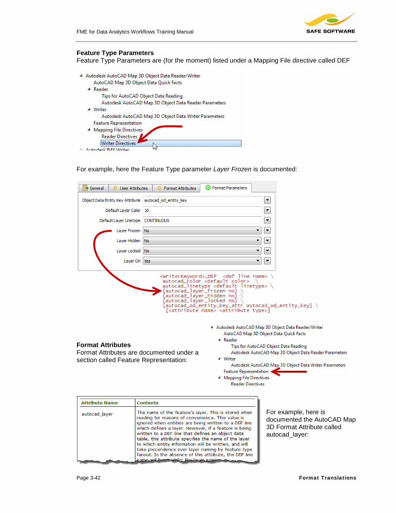
FME for Data Analytics Workflows Training Manual
Page 3-42 Format Translations
Feature Type Parameters Feature Type Parameters are (for the moment) listed under a Mapping File directive called DEF
For example, here the Feature Type parameter Layer Frozen is documented:
Format Attributes Format Attributes are documented under a section called Feature Representation:
For example, here is documented the AutoCAD Map 3D Format Attribute called autocad_layer:

FME for Data Analytics Workflows Training Manual
Format Translations Page 3-43
Published Parameters Publishing parameters is a method by which FME prompts to change read and write control parameters at runtime.
As shown, each different level of translation hierarchy has a related set of control parameters. However, there are two potential users of FME; a workspace author and the end-user. Ideally, if the end-user wanted to change one or more of these parameters, they should not need to edit the workspace in the same way that an author would. Published Parameters provide this functionality. Publishing parameters is a way to prompt the end user to enter a value, in much the same way that FME will prompt for any undefined mandatory parameters. Prompting the user for values thus avoids the need to make manual edits in the workspace. Any setting that can be defined through the Navigator window is capable of being set as a published parameter. This includes most workspace parameters, all reader and writer parameters, and all feature type parameters.
Chef Bimm says…
“Think of Published Parameters as your coffee options printed on the side of a paper cup.
They are a way for a customer to have their wishes defined without setting the machine themself”.
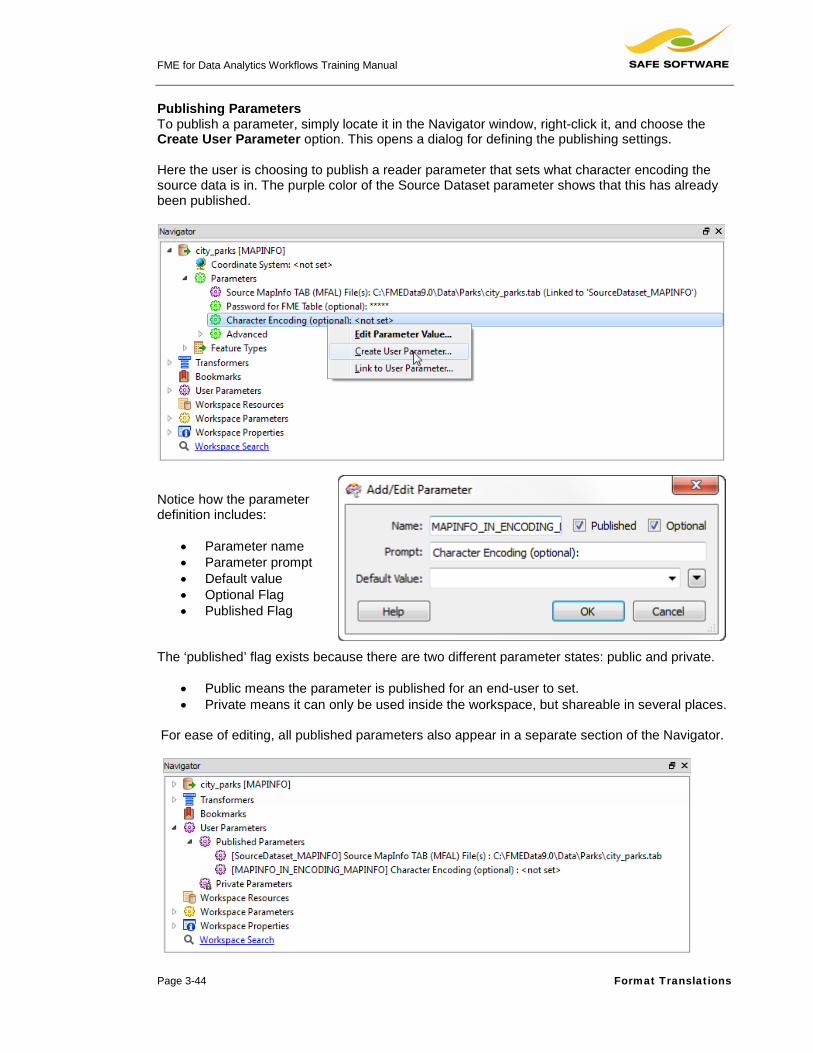
FME for Data Analytics Workflows Training Manual
Page 3-44 Format Translations
Publishing Parameters To publish a parameter, simply locate it in the Navigator window, right-click it, and choose the Create User Parameter option. This opens a dialog for defining the publishing settings. Here the user is choosing to publish a reader parameter that sets what character encoding the source data is in. The purple color of the Source Dataset parameter shows that this has already been published.
Notice how the parameter definition includes:
• Parameter name • Parameter prompt • Default value • Optional Flag • Published Flag
The ‘published’ flag exists because there are two different parameter states: public and private.
• Public means the parameter is published for an end-user to set. • Private means it can only be used inside the workspace, but shareable in several places.
For ease of editing, all published parameters also appear in a separate section of the Navigator.

FME for Data Analytics Workflows Training Manual
Format Translations Page 3-45
Publishing Workspace Parameters To publish a workspace parameter simply locate the parameter in the Navigator, right-click, and choose Create User Parameter. The limitation here is that many basic parameters (such as Destination Redirect or Workspace Password) can’t be published because it doesn’t make sense to do so. In such cases that option is simply left off the menu: Publishing Reader/Writer Parameters Publishing Reader and Writer parameters is the most common use of this functionality. It is achieved by using the same right-click context menu in the Navigator window.
Notice that some parameters are automatically published by FME. That’s because these are common parameters the user will often need to set; for example reader input file and writer output file locations.
If it’s not appropriate for a user to select these, then the published parameters can be simply removed. Publishing Feature Type Parameters For Feature Type parameters, it’s important to notice that these can only be published in the Navigator window. There are NO right-click > publish options in the Feature Type Properties dialog.
First-Officer Transformer says…
‘Besides translation components for reading and writing, you can also publish parameters for transformers; again by locating the parameter to be published in the Navigator window, right-clicking, and choosing Create User Parameter.’

FME for Data Analytics Workflows Training Manual
Page 3-46 Format Translations
Using Published Parameters Published parameters are activated whenever a workspace is run using the option File > Prompt and Run Translation from the menu bar in FME Workbench. The shortcut for this command is Ctrl+R and there is a related Prompt and Run button on the toolbar.
When a workspace is run in prompt mode, the user receives a dialog prompting them to enter new values.
Running a workspace in the FME Quick Translator always prompts for parameters; which is why it’s so suitable for non-FME-authoring end-users to run a workspace. Published Parameters on the Command Line In the same way that FME translations can be run from the command line, they can be passed values to published parameters on the command line using the syntax:
--<Parameter Name> <Parameter Value> Notice that the parameter name matches that supplied in the published parameter definition.
As usual, the log window reveals the command line used in the above translation.
The command line in the Log window specifically states ‘Windows command-line’. The biggest difference between Windows and UNIX shells is how parameters with spaces in them are quoted.
Note: The simpler File > Run (shortcut F5) will not prompt for values, but re-use existing ones.

FME for Data Analytics Workflows Training Manual
Format Translations Page 3-47
Published Parameters will let us give the end user control over how the translation works. 1) Start Workbench Start Workbench (if necessary) and open the workspace from Example 10. Alternatively you can open C:\FMEData\Workspaces\DAManual\Example11Begin.fmw 2) Publish Parameter One thing we want to do is let the user specify the size of the grid squares used to aggregate the point data. This can be done with a Published Parameter. In the Navigator window browse to the 2DGridAccumulator transformer and expand its list of parameters. Right click on ‘Column Width’, and select ‘Create user parameter’. When prompted, set up the following parameters:
Type = float Name = GridSize Published = yes Optional = no Prompt = Grid size in meters Default value = 1000
Example 11: Allow User Control
Scenario FME user; City of Interopolis, Planning Department
Data CSV format dataset of Cell Phone towers
Overall Goal Create spatial data and extract information for use in Data Analytics
Demonstrates Published Parameters
Starting Workspace C:\FMEData\Workspaces\DAManual\Example11Begin.fmw
Finished Workspace C:\FMEData\Workspaces\DAManual\Example11Complete.fmw

FME for Data Analytics Workflows Training Manual
Page 3-48 Format Translations
3) Link Parameter Because we only want square grid sizes, Row Height can share the same published parameter as Column Width; otherwise they would need one each and the user have to enter the same information twice. So, right click on Row Height, and select “Link to user parameter”. When prompted, and select “GridSize” as the user parameter to link to.
4) Publish Parameter – 2 The user may also want to select how many lines (features) are read from the CSV file. Again in the Navigator, locate the CSV reader “Max Features to Read” parameter, right-click it, and then select ‘Create user parameter’. The default values will work. 5) Run the Translation Save the translation. This time run it using the Prompt and Run Button (or File > Prompt and Run from the menu bar, or the shortcut key Ctrl+R). Experiment using different values for each of the two new published parameters. 6) Advanced Task As a couple of advanced tasks:
• Remove the existing published parameters for Source CSV File and Destination MapInfo Directory. We don’t want the end user to be setting these.
• Edit the definitions of the two published parameters you just created. Is there a better
parameter type you could use instead of Float and Integer? Would a drop-down list (Choice) work? Or maybe a Slider type would be useful?

FME for Data Analytics Workflows Training Manual
Format Translations Page 3-49
Conditional Actions Conditional Actions are where the behaviour of an FME transformer is dictated by the result of a test or condition.
Conditions can be described as IF THIS, THEN THAT, sometimes with an ELSE tacked on. For example, IF you've attended this FME training course, THEN you'll know there is a section on Conditions, ELSE you will be unaware of how useful Conditions are! The majority of cases are either for Filtering or for Mapping. Conditional Filtering Filtering (or Branching) uses conditions to subdivide data as it flows through a workspace. An analogy is: IF you are a BUS, THEN follow this road, ELSE, IF you are a CAR, THEN follow this road, ELSE, IF you are a TRUCK, THEN follow this road. In FME the GeometryFilter transformer is a good example. It has multiple output ports, each of which carries data off in a different direction. Check out the Filters category of the Transformer Gallery for more examples. In the GeometryFilter the conditions for dividing data are defined by FME. But in other transformers the decision about which features are output to which port is decided by a user-defined test. The Tester transformer, among many others, is the prime example of this.
Conditional Mapping Attribute Mapping is another common use for conditions in FME. Data doesn't get divided but instead an attribute is set to define the result. To use the same analogy: IF you are a BUS, THEN you get a red sticker, ELSE, IF you are a CAR, THEN you get an orange sticker, ELSE, IF you are a TRUCK, THEN you get a green sticker. Conditional Mapping is - like conditional filtering - where the user defines the tests and conditions for the mapping to occur. Again there are many transformers that can do this.
Although we use the term “mapping”, virtually any transformer in FME that creates an attribute will let you do so conditionally. The prime example is the AttributeCreator. Conditions are set in transformers on the drop-down menu for attribute values:

FME for Data Analytics Workflows Training Manual
Page 3-50 Format Translations
One other published parameter we could create is the ability to decide whether grid size is to be provided in feet or metres. But this sets up a condition that the 2DGridAggregator must handle. 1) Start Workbench Start Workbench (if necessary) and open the workspace from Example 11. Alternatively you can open C:\FMEData\Workspaces\DAManual\Example12Begin.fmw 2) Create Published Parameter In the Navigator window, locate the list of User Parameters. Right-click on the User Parameters heading and choose the option Add Parameter. Define a new parameter as follows: Type: Choice Name: GridUnits Published: Yes Optional: No Prompt: Units for Grid Size For Configuration, click the […] button to open the configuration dialog. Create two choices: Feet and Metres. Click OK to accept the list, then again to create the new Parameter. 3) Organize Parameters In the list of Published Parameters, delete the ones for Source and Destination datasets (if you haven’t already). Reorganize the order of the remaining parameters (you can use a drag-and-drop action) to be:
• GridSize • GridUnits • MAX_FEATURES
Edit the prompt for the GridSize parameter to remove the “in Metres” part. The user now has a choice.
Example 12: Handle Unit Choices and Clean Up Workspace
Scenario FME user; City of Interopolis, Planning Department
Data CSV format dataset of Cell Phone towers
Overall Goal Create spatial data and extract information for use in Data Analytics
Demonstrates Conditional Processing, Published Parameters, Schema Editing, Data Styling
Starting Workspace C:\FMEData\Workspaces\DAManual\Example12Begin.fmw
Finished Workspace C:\FMEData\Workspaces\DAManual\Example12Complete.fmw

FME for Data Analytics Workflows Training Manual
Format Translations Page 3-51
4) Setup 2DGridAccumulator Now open the parameters dialog for the 2DGridAccumulator transformer. It will have changed its appearance because two of the parameters have been published, and will now look like this.
Click the drop-down arrow for the Column Width parameter, and choose the option Set to Conditional Value.
In the Parameter Condition Definition dialog, double-click in the first Test Condition Field: This now opens up a test dialog, very similar to the Tester transformer or Data Inspector filter tool.
For the Left Value select Parameter > GridUnits, for the operator choose Equals (=). For the Right Value manually type in the word Metres. In the Output Value field (at the foot of the dialog) select Link to Parameter > GridSize Essentially this mapping says, IF the chosen units=Metres, THEN grid size remains unchanged. Click OK to close this dialog.

FME for Data Analytics Workflows Training Manual
Page 3-52 Format Translations
Back in the Parameter Condition Definition dialog, we can now just set up an ELSE action. There’s no need to do another test because if the chosen units aren’t metres, then they must be feet. So, double-click in the Else Output Value field and from the drop-down list select Open Arithmetic Editor. The transformer expects metres, so if the user is entering feet we need to do a calculation to correct it. In the arithmetic editor, expand the list of Published Parameters and double-click on GridSize to add it to the arithmetic expression. Then manually type in: /3.2808 This sets up the expression to be $(GridSize) / 3.2808
3.2808 is the number of feet in a metre. The result will be the user’s feet value, converted into metres, which is the units used in the dynamic Coordinate System. Now the user can enter their grid size in feet or metres and have it work correctly. Click OK, then once more to return to the main 2DGridAccumulator parameter dialog. Then repeat this step for the Row Height parameter, after which the dialog will look like this: Click OK to close it.

FME for Data Analytics Workflows Training Manual
Format Translations Page 3-53
5) Clean Up Schema There’s just one last task to do before we can run the workspace for real: clean up the output schema. At the moment it has none of the attributes defined to store the required output. Open the properties dialog for the Writer feature type. Click on the User Attributes tab and delete all the existing attributes. Then add a set of new attributes as follows: StationIDs char 255 MeasureCount char 255 PowerMin float PowerMax float PowerMean float QualityMin float QualityMax float QualityMean float
Then connect up the appropriate attributes from the FeatureMerger to the Feature Type (for example connect Quality._min to QualityMin.

FME for Data Analytics Workflows Training Manual
Page 3-54 Format Translations
6) Run Workspace Ensure that Writers > Redirect to Inspection Application is turned off. Delete any remaining Inspector transformers. Now save the workspace and then run it using File > Prompt and Run. Experiment with using different values for grid size and units. What do you notice about the performance compared to the grid size? Inspect the output in the FME Data Inspector to ensure it is correct. Congratulations! You have now finished this project! 7) Advanced Tasks OK, there are a couple of other things we can do to finish up. Manual attribute mapping – i.e. dragging connections like we just did – is frowned upon in FME because such connections are liable to be broken. So, right-click on the dark connection between the FeatureMerger and the writer Feature Type and choose the option Replace with AttributeCopier. Can you see what has happened? The fragile links have been replaced by a more robust transformer mapping. The other task we can do is add a MapInfoStyler transformer, just before the writer Feature Type, in order to style the data to look good in MapInfo; so try that.
And, finally, if you are up for the challenge, you can try running the workspace on the entire set of features. You can do this by simply deleting whatever value is in the Max Features to Read parameter and leaving it empty. On my computer, with a 5000 metre grid, it ran in four minutes.