F²MC-8FX FAMILY - Fujitsu Global Difference between Mode 0 and Mode 1 .....14 3.1.4 Communication...
50
Fujitsu Microelectronics (Shanghai) Co., Ltd. Application Note MCU-AN-500006-E-11 F²MC-8FX FAMILY 8-BIT MICROCONTROLLER MB95200H/210H SERIES LIN-UART APPLICATION NOTE
Transcript of F²MC-8FX FAMILY - Fujitsu Global Difference between Mode 0 and Mode 1 .....14 3.1.4 Communication...

Fujitsu Microelectronics (Shanghai) Co., Ltd. Application Note
MCU-AN-500006-E-11
F²MC-8FX FAMILY 8-BIT MICROCONTROLLER
MB95200H/210H SERIES
LIN-UART
APPLICATION NOTE

LIN-UART V1.1 Revision History
MCU-AN-500006-E-11 – Page 2
Revision History
Date Author Change of Records
2008-03-20 Glede.Luo V1.0, First draft
2008-07-22 Glede.Luo V1.1, Communication data bit description was modified. The baud rate measurement in LIN slave mode was modified.
This manual contains 50 pages.
© 2008 Fujitsu Microelectronics (Shanghai) Co., Ltd.
1. The products described in this manual and the specifications thereof may be changed without prior notice. To obtain up-to-date information and/or specifications, contact your Fujitsu sales representative or Fujitsu authorized dealer.
2. Fujitsu will not be liable for infringement of copyright, industrial property right, or other rights of a third party caused by the use of information or drawings described in this manual.
3. The contents of this manual may not be transferred or copied without the express permission of Fujitsu.
4. The products contained in this document are not intended for use with equipments which require extremely high reliability such as aerospace equipments, undersea repeaters, nuclear control systems or medical equipments for life support.
5. Some of the products described in this manual may be strategic materials (or special technology) as defined by the Foreign Exchange and Foreign Trade Control Law. In such cases, the products or portions thereof must not be exported without permission as defined under the law.

LIN-UART V1.1 Contents
MCU-AN-500006-E-11 – Page 3
Contents
REVISION HISTORY............................................................................................................ 2
CONTENTS .......................................................................................................................... 3
1 INTRODUCTION.............................................................................................................. 5
2 FUNCTIONS OF LIN-UART............................................................................................. 6
2.1 Block Diagram......................................................................................................... 6
2.2 Basic Functions....................................................................................................... 7
2.3 Registers of LIN-UART............................................................................................ 8
2.4 Interface to LIN-UART............................................................................................. 9
2.4.1 RS232 ....................................................................................................... 9
2.4.2 LIN........................................................................................................... 10
2.5 Baud Rate Generator Register (BGR) ................................................................... 11
3 ASYNCHRONOUS MODE (OPERATING MODE 0, 1) .................................................. 12
3.1 Operations in Asynchronous Mode........................................................................ 12
3.1.1 Transmit/Receive Data Format ................................................................ 12
3.1.2 Parity ....................................................................................................... 13
3.1.3 Difference between Mode 0 and Mode 1 ................................................. 14
3.1.4 Communication Setting Sequence for Asynchronous Mode..................... 15
3.2 Example Code in Asynchronous Mode (mode 0)................................................... 16
4 SYNCHRONOUS MODE (OPERATING MODE 2)......................................................... 17
4.1 Operation of Synchronous Mode (Operating Mode 2) ........................................... 17
4.1.1 Transmit/Receive Data Format ................................................................ 17
4.1.2 Clock Inversion Function.......................................................................... 17
4.1.3 Communication Setting for Synchronous Mode ....................................... 18
4.2 Example Code in Synchronous Mode (mode 2) .................................................... 19
5 LIN-BUS MODE (OPERATING MODE 3) ...................................................................... 19
5.1 Overview of LIN-Bus ............................................................................................. 19
5.1.1 Short LIN Specification ............................................................................ 19
5.2 Work on LIN-Master .............................................................................................. 19
5.2.1 LIN Master ............................................................................................... 19
5.2.2 Example Code ......................................................................................... 19
5.3 Work on LIN-Slave ................................................................................................ 19
5.3.1 LIN Slave................................................................................................. 19
5.3.2 Detecting LIN Synchronization Break....................................................... 19

LIN-UART V1.1 Contents
MCU-AN-500006-E-11 – Page 4
5.3.3 Baud Rate Measurement ......................................................................... 19
5.3.4 Example Code ......................................................................................... 19
6 ADDITIONAL INFORMATION ....................................................................................... 19
7 APPENDIX..................................................................................................................... 19
7.1 Figures .................................................................................................................. 19
7.2 Sample Code ........................................................................................................ 19
7.2.1 Project1 Name: UART_Asynchronous ..................................................... 19
7.2.2 Project2 Name: UART_Synchronous....................................................... 19
7.2.3 Project3 Name: UART_LIN_Master ......................................................... 19
7.2.4 Project4 Name: UART_LIN_Slave ........................................................... 19

LIN-UART V1.1 Chapter 1 Introduction
MCU-AN-500006-E-11 – Page 5
1 Introduction
This application note describes how to use the LIN-UART in various modes.
This note describes functions of the LIN-UART and their operation modes and gives some example code. The LIN-UART has four operating modes. Operating mode 0 is asynchronous (normal mode), operating mode 1 is asynchronous (multiprocessor mode), operating mode 2 is synchronous (normal mode) and operating mode 3 is asynchronous (LIN mode).

LIN-UART V1.1 Chapter 2 Functions of LIN-UART
MCU-AN-500006-E-11 – Page 6
2 Functions of LIN-UART
This section describes functions of the LIN-UART
The LIN (Local Interconnect Network)-UART is a general-purpose serial data communication interface for synchronous or asynchronous (start-stop synchronization) communication with external devices. In addition to a bi-directional communication function (normal mode) and master/slave communication function (multiprocessor mode: supports both master and slave operation), the LIN-UART also supports the special functions used by the LIN bus.
2.1 Block Diagram
Figure 2.1-1 shows the internal block diagram of the LIN-UART.
Figure 2.1-1 : LIN-UART Block Diagram

LIN-UART V1.1 Chapter 2 Functions of LIN-UART
MCU-AN-500006-E-11 – Page 7
2.2 Basic Functions
The LIN-UART operates in four different modes. The operating mode is selected by the MD0 and MD1 bits in the LIN-UART serial mode register (SMR). Mode 0 and mode 2 are used for bi-directional serial communication; mode 1 for master/slave communication; and mode 3 for LIN master/slave communication.
Data length
Operating mode
No parity With parity
Synchronous method
Stop bit length
Data bit format
0 Normal mode 7 bits or 8 bits Asynchronous
1 Multiprocessor
mode 7 bits or
8 bits +1* - Asynchronous
1 bit or 2 bits
2 Normal mode 8 bits Synchronous None, 1 bit,
2 bits
LSB first MSB first
3 LIN mode 8 bits - Asynchronous 1 bit LSB first
Figure 2.2-1 : LIN-UART Operating Modes
- : Unavailable
*: "+1" is the address/data selection bit (AD) used for communication control in multiprocessor mode.
The MD0 and MD1 bits in the LIN-UART serial mode register (SMR) are used to select the following LIN-UART operating modes.
MD1 MD0 Mode Type
0 0 0 Asynchronous (Normal mode)
0 1 1 Asynchronous (Multiprocessor mode)
1 0 2 Synchronous (Normal mode)
1 1 3 Asynchronous (LIN mode)
Figure 2.2-2 : LIN-UART Operating Modes
• Mode 1 supports both master and slave operation in multiprocessor mode. • The communication format of Mode 3 is fixed at: 8-bit data, no parity, stop bit 1, LSB-first.

LIN-UART V1.1 Chapter 2 Functions of LIN-UART
MCU-AN-500006-E-11 – Page 8
2.3 Registers of LIN-UART
This section lists registers of the LIN-UART.
• Register List of LIN-UART
Figure 2.3-1 : Register List of LIN-UART
Figure 2.3-1 shows all registers of the LIN-UART. For detailed information, please check Chapter 16 of the MB95200 Series Hardware Manual.

LIN-UART V1.1 Chapter 2 Functions of LIN-UART
MCU-AN-500006-E-11 – Page 9
2.4 Interface to LIN-UART
2.4.1 RS232
The LIN-UART in asynchronous mode can be interfaced to the RS-232 bus through a transceiver. The transceiver provides the ability to receive and transmit messages over the bus. Figure 2.4-1 shows interfacing of MB95200 microcontroller to transceiver MAX3232CSE. The R1IN input and T1OUT output of the transceiver is connected to the TXD and RXD signals of the female DB-9 connector respectively.
Value of the capacitor used depends on the supply voltage VCC. For details, please refer to the datasheet of MAX3232CSE.
Figure 2.4-1 : LIN-UART Interface to RS-232 Bus
Note:
The circuit is a typical application when the LIN-UART is connected to different voltage conditions.

LIN-UART V1.1 Chapter 2 Functions of LIN-UART
MCU-AN-500006-E-11 – Page 10
2.4.2 LIN
The LIN-UART in LIN mode can be interfaced to the LIN bus through a transceiver. The transceiver provides the ability to receive and transmit messages over the bus. Figure 2.4-2 shows interfacing of MB95200 microcontroller to transceiver TLE7259. The Bus output/input of the transceiver is connected to Bus input/output signal of the female DB-9 connector. VBAT supply needs to be chosen within a range of 8V to 18V. Jumper J1 needs to be closed in the case of LIN-Master and opened in the case of LIN-Slave.
Figure 2.4-2 : LIN-UART Interface to LIN Bus
Note:
It is recommended using this circuit if the LIN-UART is connected to TLE7259.

LIN-UART V1.1 Chapter 2 Functions of LIN-UART
MCU-AN-500006-E-11 – Page 11
2.5 Baud Rate Generator Register (BGR)
The two 15-bit reload counters are set by the LIN-UART baud rate generator registers 1, 0 (BGR 1, BGR 0) respectively. The equation for the baud rate is shown below.
Reload value:
v: Reload value b: Baud rate MCLK: Machine clock, or external clock frequency
Calculation example: Assuming that the machine clock is 10MHz, the internal clock is used, and the baud rate is set to 19200 bps: Reload value:
Thus, the actual baud rate can be calculated as shown below.
Note:
The reload counter stops if the reload value is set to “0”. Therefore, set the smallest reload value to “1”.
For transmission/reception in asynchronous mode, since five times of oversampling has to be done before the reception value is determined, the reload value must be set to at least “4”.

LIN-UART V1.1 Chapter 3 Asynchronous Mode (Operating Mode 0, 1)
MCU-AN-500006-E-11 – Page 12
3 Asynchronous Mode (Operating Mode 0, 1)
This section introduces how to set LIN-UART registers when the LIN-UART operates in asynchronous mode: mode 0 (normal mode) or mode 1 (multiprocessor mode)
3.1 Operations in Asynchronous Mode
3.1.1 Transmit/Receive Data Format
Transmit/receive data always begins with a start bit ("L" level), followed by a specified data bits length and ends with at least one stop bit ("H" level).
The bit transfer direction (LSB-first or MSB-first) is determined by the BDS bit in the LIN-UART serial status register (SSR). When the parity bit is used, it is always placed between the last data bit and the first stop bit.
Figure 3.1-1 : Transmit/Receive Data Format (Operating Mode 0, 1)
Note:
If the BDS bit in the LIN-UART serial status register (SSR) is set to "1" (MSB-first), the bits are processed in the following order: D7, D6 ......D1, D0 (P).
LIN-UART V1.1 Chapter 3 Asynchronous Mode (Operating Mode 0, 1)
MCU-AN-500006-E-11 – Page 13
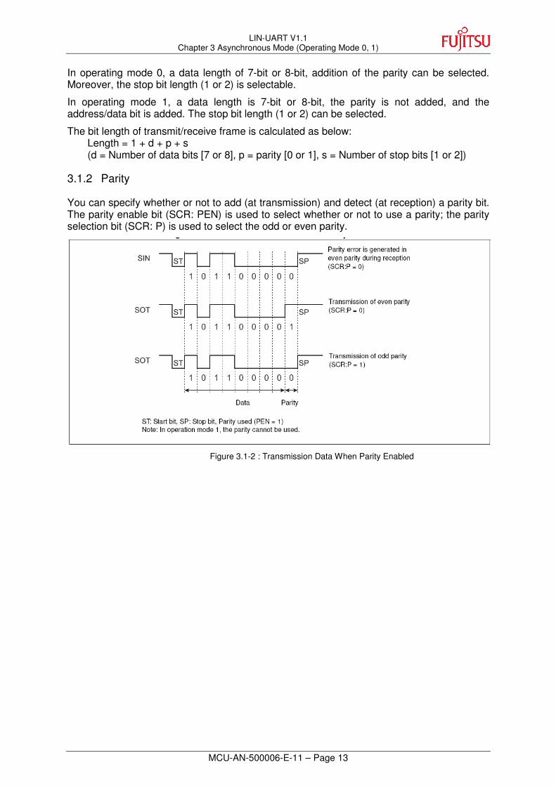
In operating mode 0, a data length of 7-bit or 8-bit, addition of the parity can be selected. Moreover, the stop bit length (1 or 2) is selectable.
In operating mode 1, a data length is 7-bit or 8-bit, the parity is not added, and the address/data bit is added. The stop bit length (1 or 2) can be selected.
The bit length of transmit/receive frame is calculated as below: Length = 1 + d + p + s (d = Number of data bits [7 or 8], p = parity [0 or 1], s = Number of stop bits [1 or 2])
3.1.2 Parity
You can specify whether or not to add (at transmission) and detect (at reception) a parity bit. The parity enable bit (SCR: PEN) is used to select whether or not to use a parity; the parity selection bit (SCR: P) is used to select the odd or even parity.
Figure 3.1-2 : Transmission Data When Parity Enabled

LIN-UART V1.1 Chapter 3 Asynchronous Mode (Operating Mode 0, 1)
MCU-AN-500006-E-11 – Page 14
3.1.3 Difference between Mode 0 and Mode 1
Mode 0 and Mode 1 have two differences between them: hardware connection and communication data format.
• Hardware connection
Mode 0 is normal mode. It allows bidirectional communication function. For bidirectional communication, interconnect two CPUs as shown in Figure 3.1-3.
Figure 3.1-3 : Connection of Bidirectional Communication in LIN-UART Mode 0
Operating mode 1 is multiprocessor mode. The LIN-UART allows communication between multiple CPUs connected in master/slave mode. It can be used as a master or slave.
Multiprocessor mode (mode 1) communication system is configured by connecting between one master CPU and multiple slave CPUs with two common communication lines, as shown in Figure 3.1-4.
Figure 3.1-4 : Connection of LIN-UART Multiprocessor Mode Communication
• The data format of communication
• The parity
Mode 0: With parity
Mode 1: No parity
• A/D (address/data bit)
Mode 0: No address/data bit. The bidirectional transmission data do not transmit address/data bit of the two CPUs.
Mode 1: With address/data bit. The multiprocessor mode communication is started by transmitting address data from the master CPU. The master CPU communicates with the slave CPU when the address matches an assigned address of the slave CPU.

LIN-UART V1.1 Chapter 3 Asynchronous Mode (Operating Mode 0, 1)
MCU-AN-500006-E-11 – Page 15
3.1.4 Communication Setting Sequence for Asynchronous Mode
To communicate in asynchronous mode, the following sequence settings are required.
• LIN-UART baud rate generator register 1, 0 (BGR1, BGR0) Set the dedicated baud rate reload counter to a required value.
• LIN-UART serial mode register (SMR) MD1, MD0: “00B” (Mode 0) MD1, MD0: “01B” (Mode 1) SCKE : “1”: Uses the dedicated baud rate reloads counter “0”: Inputs external clock SOE : “1”: Enables transmission/reception “0”: Enables reception only
• LIN-UART serial control register (SCR) TXE : “1”: Enables transmission “0”: Disables transmission RXE : “1”: Enables reception “0”: Disables reception AD : “1”: Address frame “0”: Data frame CL : “1”: Data length selection 8 bit “0”: Data length selection 7 bit CRE : “1”: Since the error flag is cleared, transmission/reception is stopped. “0”: No effect PEN : “1”: Adds/detects parity bit “0”: Not use parity bit P : “1”: Even parity “0”: Odd parity SBL : “1”: Stop bit length 2 “0”: Stop bit length 1
• LIN-UART serial status register (SSR) BDS : “1”: MSB-first “0”: LSB-first RIE : “1”: Enables reception interrupt
“0”: Disables reception interrupt TIE : “1”: Enables transmit interrupt,
“0”: Disables transmit interrupt
• LIN-UART extended communication control register (ECCR) SSM : “0”: Not use start/stop bit (normal),
“1”: Uses start/stop bit (extended function), MS : “0”: Transmission side of serial clock (serial clock output),
“1”: Reception side of serial clock (input serial clock from the transmission side of serial clock)

LIN-UART V1.1 Chapter 3 Asynchronous Mode (Operating Mode 0, 1)
MCU-AN-500006-E-11 – Page 16
3.2 Example Code in Asynchronous Mode (mode 0)
The example code describes how to use the LIN-UART and set its registers in operation mode 0.
Note:
The full example code is referred to as project 1 UART_Asynchronous.
/***********************************************************************
/* The MCU operates in mode0 (asynchronous mode).
/* The baud rate = 9600b, MCLK = 8MHZ.
***********************************************************************/
/***********************************************************************
NAME : UART_init ()
FUNCTION: Initialize the LIN-UART in operation mode 0(asynchronous mode)
***********************************************************************/
void UART_init (void)
{
BGR1 = 0x03; // BGR1 = 0x03 (8MHz, 9600Baud)
BGR0 = 0x40; // BGR0 = 0x40 (8MHz, 9600Baud)
SMR = 0x05; // enable SOT, Reset, asynchronous mode 0
SSR = 0x00; // clear flags, no interrupt
SCR = 0x13; // enable transmit
}
/***********************************************************************
NAME : UART_ readbyte ()
FUNCTION: receive a byte
***********************************************************************/
char UART_readbyte (void)
{
while (! SSR_RDRF); // wait, until a byte is received
return (RDR_TDR); // return the received byte
}
/***********************************************************************
NAME : UART_ sendbyte ()
FUNCTION: transmit a byte
***********************************************************************/
void UART_sendbyte (char ch)
{
while (! SSR_TDRE); // wait, until a byte is transmited
RDR_TDR= ch; // transmit the byte (ch)
}

LIN-UART V1.1 Chapter 4 Synchronous Mode (Operating Mode 2)
MCU-AN-500006-E-11 – Page 17
4 Synchronous Mode (Operating Mode 2)
This section introduces how to set LIN-UART registers when the LIN-UART operates in synchronous mode (mode 2)
4.1 Operation of Synchronous Mode (Operating Mode 2)
4.1.1 Transmit/Receive Data Format
In synchronous mode, 8-bit data is transmitted and received; the addition of the start bit and the stop bit can be selected(ECCR: SSM). When the start/stop bits are added to the data format (ECCR: SSM = 1), the addition of the parity bit can also be selected (SCR: PEN).
Figure 4.1-1 : Transmit/Receive Data Format (Operating Mode 2)
4.1.2 Clock Inversion Function
When the SCES bit in the LIN-UART extended status control register (ESCR) is "1", the serial clock is inverted. If the reception side of serial clock is selected, the LIN-UART samples data at the falling edge of the received serial clock. If the transmission side of serial clock is selected, the mark level is set to "0" when the SCES bit is "1".
Figure 4.1-2 : Transmission Data Format during Clock Inverted

LIN-UART V1.1 Chapter 4 Synchronous Mode (Operating Mode 2)
MCU-AN-500006-E-11 – Page 18
4.1.3 Communication Setting for Synchronous Mode To communicate in synchronous mode, the following settings are required.
• LIN-UART baud rate generator register 1, 0 (BGR1, BGR0) Set the dedicated baud rate reload counter to a required value.
• LIN-UART serial mode register (SMR) MD1, MD0: “10B” (Mode 2) SCKE : “1”: Uses the dedicated baud rate reloads counter “0”: Inputs external clock SOE : “1”: Enables transmission/reception “0”: Enables reception only
• LIN-UART serial control register (SCR) TXE : “1”: Enables transmission “0”: Disables transmission RXE : “1”: Enables reception “0”: Disables reception AD : “1”: Address frame “0”: Data frame CL : “1”: Data length selection 8 bit “0”: Data length selection 7 bit CRE : “1”: Since the error flag is cleared, transmission/reception is stopped. “0”: No effect PEN : “1”: Adds/detects parity bit “0”: Not use parity bit P : “1”: Even parity “0”: Odd parity SBL : “1”: Stop bit length 2 “0”: Stop bit length 1
• LIN-UART serial status register (SSR) BDS : “1”: MSB-first “0”: LSB-first RIE : “1”: Enables reception interrupt
“0”: Disables reception interrupt TIE : “1”: Enables transmit interrupt,
“0”: Disables transmit interrupt
• LIN-UART extended communication control register (ECCR) SSM : “0”: Not use start/stop bit (normal),
“1”: Uses start/stop bit (extended function), MS : “0”: Transmission side of serial clock (serial clock output),
“1”: Reception side of serial clock (input serial clock from the transmission side of serial clock)

LIN-UART V1.1 Chapter 4 Synchronous Mode (Operating Mode 2)
MCU-AN-500006-E-11 – Page 19
4.2 Example Code in Synchronous Mode (mode 2)
The example codes describe how to use the LIN-UART and set its registers in operating mode 2(synchronous mode).
Note:
The full example code is referred to as project 2 UART_Synchronous.
/***********************************************************************
/* The MCU operates in mode2 (synchronous mode).
/* The baud rate = 9600b, MCLK = 8MHZ.
***********************************************************************/
/***********************************************************************
NAME : UART_init ()
FUNCTION: Initialize the LIN-UART in operation mode 2(synchronous mode)
***********************************************************************/
void UART_init (void)
{
BGR1 = 0x00; // BGR1 = 0x00 (SCK = 500 KHz, 9600 Baud)
BGR0 = 0x33; // BGR0 = 0x33 (SCK = 500 KHz, 9600 Baud)
SMR = 0x87; // enable SOT, Reset, synchronous mode
SSR = 0x00; // clear flags, no interrupt
ECCR_SSM = 1; // have ST/STP bit
SCR = 0xc3; // enable transmit, add parity
}
/***********************************************************************
NAME : UART_ readbyte ()
FUNCTION: receive a byte
***********************************************************************/
void UART_sendbyte (char ch)
{
while (! SSR_TDRE); // wait, until a byte is transmited
RDR_TDR= ch; // transmit the byte (ch)
}
/***********************************************************************
NAME : UART_ sendbyte ()
FUNCTION: transmit a byte
***********************************************************************/
char UART_readbyte_wait (void)
{
while (! SSR_RDRF); // wait, until a byte is received
return (RDR_TDR); // return the received byte }

LIN-UART V1.1 Chapter 5 LIN-Bus Mode (Operating Mode 3)
MCU-AN-500006-E-11 – Page 20
5 LIN-Bus Mode (Operating Mode 3)
This section introduces how to set LIN-UART registers when the LIN-UART operates in LIN-Bus mode (operating mode 3).
5.1 Overview of LIN-Bus
5.1.1 Short LIN Specification A LIN message frame consists of a header and a response as shown in the graph below:
Figure 5.1-1 : LIN Message Frame
Except for the synchronization break, all fields are simple 8N1L data, which means 1 start bit, 8 data bits (LSB first), no parity, 1 stop bit. This break is specified as below:
Figure 5.1-2 : Synch Break Field Cycle
Figure 5.1-3 : Synch Break Field

LIN-UART V1.1 Chapter 5 LIN-Bus Mode (Operating Mode 3)
MCU-AN-500006-E-11 – Page 21
As the synchronization field is a simple 0x55 byte (LSB first), it consists of 5 dominant and 5 recessive bits:
Figure 5.1-4 : Synch Field Data Format
All other fields are also simple 8N1L data whose contents do not need special processing by the hardware.

LIN-UART V1.1 Chapter 5 LIN-Bus Mode (Operating Mode 3)
MCU-AN-500006-E-11 – Page 22
5.2 Work on LIN-Master
5.2.1 LIN Master
The LIN master controls the entire sub bus. The master starts a LIN message frame with the LIN synchronization break, followed by the synchronization field 0x55 and the identifier field.
The length of the break can be set with the control bits LBL0, LBL1 in the extended status/control register (ESCR) of the LIN-UART.
Figure 5.2-1 : Communication Data Bit
* based on master’s own time base
The following graph shows the timing of different settings:
Figure 5.2-2 : Timing setting
Because transmitting this break LIN-UART has to be in LIN-mode (mode 3), the LBR control bit in the extended communication control register (ECCR) has to be set to “1”. At the next internal serial clock cycle the break signal will be generated.
At this moment “normal” 8N1L transmission is blocked, but the 0x55 byte for the synchronization field can be set at this time. After the break a recessive level is set to the serial output and is held for 1 bit time. Then the synchronization field (0x55) starts.

LIN-UART V1.1 Chapter 5 LIN-Bus Mode (Operating Mode 3)
MCU-AN-500006-E-11 – Page 23
The following graph illustrates this timing:
Figure 5.2-3 : Timing Setting
Since the LIN is single wire network, the master can read back its own transmissions. Therefore enabling the reception after a LIN-break detection (which was set by the master itself) is recommended. The master then receives the synchronization field as a normal 0x55 data and thus is synchronized with the protocol.
Note, that after a complete LIN-message, the reception has to be disabled again so that the LIN-break can be detected without getting a framing error.

LIN-UART V1.1 Chapter 5 LIN-Bus Mode (Operating Mode 3)
MCU-AN-500006-E-11 – Page 24
5.2.2 Example Code
The example code describes how to set LIN-UART registers when the LIN-UART operates as LIN-Master (LIN asynchronous mode/mode 3).
Note:
The full example code is referred to as project 3 UART_LIN_Master.
/**********************************************************************
/* The MCU operates in mode3 (LIN mode).
/* The baud rate = 9600b, MCLK = 8MHZ.
**********************************************************************/
/**********************************************************************
NAME : InitUart ()
FUNCTION: Initialize UART asynchronous LIN mode
**********************************************************************/
void InitUart (void)
{
BGR1 = 0x03; // BGR1 = 0x03 (8MHz, 9600Baud)
BGR0 = 0x40; // BGR0 = 0x40 (8MHz, 9600Baud)
SSR = 0x02; // enable reception interrupt
SCR = 0x01; // enable transmit
ESCR = 0x30; // set LIN break 16 bit times
}
/**********************************************************************
NAME : Start_LIN_Message ()
FUNCTION: initialize ESCR and LIN_State
**********************************************************************/
void Start_LIN_Message (void)
{
ESCR_LBD = 0; // clear possible LIN-Break detection
ESCR_LBIE = 1; // enable LIN Break detection (for read back)
ECCR = 0x40; // Generate LIN-Break
}
/**********************************************************************
NAME : __interrupt void IRQ_LIN_RX ()
FUNCTION: transmit and receive data in interrupt function
**********************************************************************/
__interrupt void IRQ_LIN_RX (void)
{
if (ESCR_LBD) // LIN Break Detection (Read back)?
{
ESCR_LBD = 0; // Clear flag
}
else if (SSR_RDRF) // Reception?
{
Rx_Data = RDR_TDR; // Get reception data
}
else // Not recognized interrupt cause
{
SSR_RIE = 0; // disable reception interrupt
}
}

LIN-UART V1.1 Chapter 5 LIN-Bus Mode (Operating Mode 3)
MCU-AN-500006-E-11 – Page 25
5.3 Work on LIN-Slave
5.3.1 LIN Slave
A LIN slave is connected to the entire LIN sub bus. To react to a LIN break is stringent. The identifier field then locates a specified slave for responding.
To receive the identifier correctly each slave has to adjust to the LIN master’s baud rate. Therefore the slave has to measure the LIN synchronization field. The result of this measurement is used for the slave baud rate’s adjustment.
Note that this measurement is necessary only when the slave baud rate differs up to ±15% from the master baud rate (e. g. when RC oscillator is used for slave clock). Because the LIN-UART is synchronizing its internal clock with the falling edge of the start bit, and samples each bit in the middle of the bit time, a theoretical deviation of about ±5% is tolerable (for 8N1 data format). The following illustration is an example for 115.2kbit/s:
Figure 5.3-1 : 8N1 Data Format

LIN-UART V1.1 Chapter 5 LIN-Bus Mode (Operating Mode 3)
MCU-AN-500006-E-11 – Page 26
5.3.2 Detecting LIN Synchronization Break
The threshold time of the detection is 11 1/2 dominant bits:
Figure 5.3-2 : LIN Synchronization Break
If the LIN break detection interrupt is enabled (ESCR_LBIE = 1) and the normal data reception is disabled (SCR_RXE = 0), a reception interrupt is generated when the ESCR_LBD bit is set by the hardware.
Note that if a recessive stop bit is expected to be normal, data reception has to be disabled to avoid a framing error (and an additional interrupt) at bit time 9. Even if no interrupt is generated, the LBD flag has to be cleared by writing “0” to it after a break has been detected.

LIN-UART V1.1 Chapter 5 LIN-Bus Mode (Operating Mode 3)
MCU-AN-500006-E-11 – Page 27
5.3.3 Baud Rate Measurement
If the LIN-UART has detected a LIN Break it waits for the synchronization field. Within this field an internal signal is generated from the first falling edge to the 5th falling edge. The following graph illustrates this:
Figure 5.3-3 : First Falling Edge of LIN
This internal signal is connected to an Input Capture Unit (ICU) of the MCU. For the connection between ICU and LIN UART, please refer to the hardware manual.
The ICU has to be set to “both edge” detection ( ). At edge 1 an interrupt is initiated. The user program has to store the actual value of the ICU counter. At edge 5 the second interrupt is initiated. The actual value minus the stored divided by 8 is the new baud rate.
This simple algorithm without rounding is accurate enough, so that the calculation result directly can be stored into the baud rate reload counter register. The uncertainty is about 1 LSB anyway, but always within the allowed ±5% tolerance.
The calculation of baud rate is illustrated below using the operation of the LIN-UART as an example. When the LIN-UART detects the first falling edge of the synch field, set the internal signal to be input to the 8/16-bit composite timer to "H", and then start the 8/16-bit composite timer. The internal signal becomes "L" at the fifth falling edge. The 8/16-bit composite timer must be set to the input capture mode. In addition, the 8/16-bit composite timer interrupt must be enabled and the 8/16-bit composite timer must be set to detect both edges. The time at which the input signal input to the 8/16-bit composite timer is eight times the baud rate.
The baud rate setting can be found by the following equations.
When the counter of the 8/16-bit composite timer does not overflow:
BGR value = (b - a) / 8 – 1
When the counter of the 8/16-bit composite timer has overflowed:
BGR value = (max + b - a) / 8 - 1
max: Maximum value of free-run timer
a: TII0 data register value after the first interrupt
b: TII0 data register value after the second interrupt

LIN-UART V1.1 Chapter 5 LIN-Bus Mode (Operating Mode 3)
MCU-AN-500006-E-11 – Page 28
5.3.4 Example Code
The example codes describe how to set the LIN-UART registers when the LIN-UART operates as LIN-Slave (LIN asynchronous mode/mode 3).
Note:
The full example code is referred to as project 4 UART_LIN_Slave.
/***********************************************************************
/* The MCU operates as LIN mode (LIN-Slave).
/* The baud rate = 9600b, MCLK = 8MHZ.
**********************************************************************/
/**********************************************************************
NAME : InitUart ()
FUNCTION: Initialize the UART in asynchronous LIN mode
**********************************************************************/
void InitUart (void)
{
BGR1 = 0x03; // BGR1 = 0x03 (8MHz, 9600Baud)
BGR0 = 0x40; // BGR0 = 0x40 (8MHz, 9600Baud)
SMR = 0xC5; // enable SOT, Reset, LIN mode
SSR = 0x02; // enable reception interrupt
SCR = 0x01; // enable transmit
ESCR = 0x80; // enable LIN break detection interrupt
}
/**********************************************************************
NAME : __interrupt void IRQ_LIN_RX ()
FUNCTION: transmit and receive data in interrupt function
**********************************************************************/
__interrupt void IRQ_LIN_RX (void)
{
if (ESCR_LBD) // LIN Break Detection (Read back)?
{
ESCR_LBD = 0; // Clear flag
}
else if (SSR_RDRF) // Reception?
{
Rx_Data = RDR_TDR; // Get reception data
}
else // Not recognized interrupt cause
{
SSR_RIE = 0; // disable reception interrupt
}
}

LIN-UART V1.1 Chapter 6 Additional Information
MCU-AN-500006-E-11 – Page 29
6 Additional Information
For more information on FUJITSU microcontroller products, please visit the following websites at:
Simplified Chinese Version: http://www.fujitsu.com/cn/fmc/services/mcu/mb95200/
English Version: http://www.fujitsu.com/cn/fmc/en/services/mcu/mb95200/

LIN-UART V1.1 Chapter 7 APPENDIX
MCU-AN-500006-E-11 – Page 30
7 APPENDIX
7.1 Figures
Figure 2.1-1 : LIN-UART Block Diagram ................................................................................ 6
Figure 2.2-1 : LIN-UART Operating Modes ............................................................................ 7
Figure 2.2-2 : LIN-UART Operating Modes ............................................................................ 7
Figure 2.3-1 : Register List of LIN-UART................................................................................ 8
Figure 2.4-1 : LIN-UART Interface to RS-232 Bus.................................................................. 9
Figure 2.4-2 : LIN-UART Interface to LIN Bus ...................................................................... 10
Figure 3.1-1 : Transmit/Receive Data Format (Operating Mode 0, 1) ................................... 12
Figure 3.1-2 : Transmission Data When Parity Enabled ....................................................... 13
Figure 3.1-3 : Connection of Bidirectional Communication in LIN-UART Mode 0 ................. 14
Figure 3.1-4 : Connection of LIN-UART Multiprocessor Mode Communication .................... 14
Figure 4.1-1 : Transmit/Reception Data Format (Operating Mode 2).................................... 17
Figure 4.1-2 : Transmission Data Format during Clock Inverted........................................... 17
Figure 5.1-1 : LIN Message Frame....................................................................................... 19
Figure 5.1-2 : Synch Break Field Cycle ................................................................................ 19
Figure 5.1-3 : Synch Break Field.......................................................................................... 19
Figure 5.1-4 : Synch Field Data Format ............................................................................... 19
Figure 5.2-1 : Communication Data Bit ................................................................................ 19
Figure 5.2-2 : Timing setting................................................................................................. 19
Figure 5.2-3 : Timing Setting ................................................................................................ 19
Figure 5.3-1 : 8N1 Data Format ........................................................................................... 19
Figure 5.3-2 : LIN Synchronization Break............................................................................. 19
Figure 5.3-3 : First Falling Edge of LIN................................................................................. 19

LIN-UART V1.1 Chapter 7 APPENDIX
MCU-AN-500006-E-11 – Page 31
7.2 Sample Code
7.2.1 Project1 Name: UART_Asynchronous
NAME : UART_Asynchronous
FUNCTION: receive a byte or transmit a byte when the LIN-UART operates in
asynchronous mode (mode 0).
main.c
#include "mb95200.h"
/******************************************************************************
NAME : UART_init ()
FUNCTION: Initialize the LIN-UART in operating mode 0(asynchronous mode)
******************************************************************************/
void UART_init (void)
{
BGR1 = 0x03; // BGR1 = 0x03 (8MHz, 9600Baud)
BGR0 = 0x40; // BGR0 = 0x40 (8MHz, 9600Baud)
SMR = 0x05; // enable SOT, Reset, asynchronous mode 0
SSR = 0x00; // clear flags, no interrupt
SCR = 0x13; // enable transmission, disable reception
}
/******************************************************************************
NAME : UART_ sendbyte ()
FUNCTION: transmit a byte
******************************************************************************/
void UART_sendbyte (char ch)
{
while (! SSR_TDRE); // wait, until a byte is transmitted
RDR_TDR= ch; // transmit the byte
}
/******************************************************************************
NAME : UART_ readbyte ()
FUNCTION: receive a byte
******************************************************************************/

LIN-UART V1.1 Chapter 7 APPENDIX
MCU-AN-500006-E-11 – Page 32
char UART_readbyte (void)
{
while (! SSR_RDRF); // wait, until byte is received
return (RDR_TDR); // return the received byte
}
/******************************************************************************
NAME : main ()
FUNCTION: asynchronously transmit a byte or receive a byte
******************************************************************************/
void main (void)
{
char rec_data = 0; // define a receive variable
char tra_data = 2; // define a transmit variable
DDR0_P00 = 1; //P00 output
DDR0_P05 =1; //P05 output
DDR0_P06 = 0; //P06 input
DDR0_P03 = 1; //P03 output
DDR0_P04 = 0; //P04 input
AIDRL = 0xff; //Port input enabled
PDR0_P00 = 0x00;
PDR0_P05 = 0x01;
UART_init (); //initialize LIN-UART
while (1)
{
UART_sendbyte (tra_data); //transmit a byte
rec_data = UART_readbyte (); //receive a byte
asm("\tNOP");
asm("\tNOP");
}
}

LIN-UART V1.1 Chapter 7 APPENDIX
MCU-AN-500006-E-11 – Page 33
7.2.2 Project2 Name: UART_Synchronous
NAME : UART_Synchronous
FUNCTION: transmit a byte or receive a byte when the LIN-UART operates in
synchronous mode (mode 2).
main.c
#include "mb95200.h"
/******************************************************************************
NAME : UART_init ()
FUNCTION: Initialize the LIN-UART in operating mode 2(synchronous mode)
******************************************************************************/
void UART_init (void)
{
BGR1 = 0x00; // BGR1 = 0x00 (SCK = 500 KHz, 9600 Baud)
BGR0 = 0x33; // BGR0 = 0x33 (SCK = 500 KHz, 9600 Baud)
SMR = 0x87; // enable SOT, Reset, synchronous mode
SSR = 0x00; // clear flags, no interrupt
ECCR_SSM = 1; // have ST/STP bit
SCR = 0xc3; // enable transmit, Odd parity
}
/******************************************************************************
NAME : UART_ readbyte ()
FUNCTION: received a byte
******************************************************************************/
char UART_readbyte (void)
{
while (! SSR_RDRF); // wait until a byte is received
return (RDR_TDR); // return the received byte
}
/******************************************************************************
NAME : UART_ sendbyte ()
FUNCTION: transmit a byte
******************************************************************************/
void UART_sendbyte (char ch)

LIN-UART V1.1 Chapter 7 APPENDIX
MCU-AN-500006-E-11 – Page 34
{
while (! SSR_TDRE);
RDR_TDR= ch; //transmit data
}
/******************************************************************************
NAME : main ()
FUNCTION: synchronously transmit a byte or receive a byte
******************************************************************************/
void main (void)
{
unsigned char rec_data = 0;
DDR0_P00 = 1; //P00 output
DDR0_P05 = 1; //P05 output
DDR0_P06 = 0; //P06 input
DDR0_P03 = 1; //P03 output
DDR0_P04 = 0; //P04 input
AIDRL = 0xff; //Port input enabled
PDR0_P00 = 0x00;
PDR0_P05 = 0x01;
UART_init ();
while (1)
{
asm("\tNOP");
UART_sendbyte(0xaa);
rec_data = UART_readbyte ();
asm("\tNOP");
asm("\tNOP");
}
}

LIN-UART V1.1 Chapter 7 APPENDIX
MCU-AN-500006-E-11 – Page 35
7.2.3 Project3 Name: UART_LIN_Master
NAME : UART_LIN_Master
FUNCTION: Receive or transmit data when the LIN-UART operates as master in LIN mode
main.c
#include "mb95200.h"
#define DATALENGTH 8
#define SLAVESEND 0x7D
#define MASTERSEND 0xFE
volatile unsigned char LIN_State, Rx_Error, Rx_Data, Master_Send;
volatile unsigned char LIN_Header, LIN_Count, LIN_Checksum;
volatile unsigned char LIN_Data[DATALENGTH];
volatile unsigned char counter;
/******************************************************************************
NAME : InitUart ()
FUNCTION: Initialize UART in asynchronous LIN mode
******************************************************************************/
void InitUart3(void)
{
BGR1 = 0x03; // BGR1 = 0x03 (8MHz, 9600Baud)
BGR0 = 0x40; // BGR0 = 0x40 (8MHz, 9600Baud)
SMR = 0xC5; // enable SOT, Reset, LIN mode
SSR = 0x02; // enable reception interrupt
SCR = 0x01; // enable transmission
ESCR = 0x30; // set LIN break 16 bit times
}
/******************************************************************************
NAME : wait ()
FUNCTION: delay time
******************************************************************************/
void wait(unsigned long j)
{

LIN-UART V1.1 Chapter 7 APPENDIX
MCU-AN-500006-E-11 – Page 36
while(j--)
{
asm("\tNOP");
WDTC=0x35; //Clear watch dog timer
}
}
/******************************************************************************
NAME : Start_LIN_Message ()
FUNCTION: initialize ESCR and LIN_State
******************************************************************************/
void Start_LIN_Message(void)
{
ESCR_LBD = 0; // clear possible LIN-Break detection
ESCR_LBIE = 1; // enable LIN Break detection (for read back)
ECCR = 0x40; // Generate LIN-Break
LIN_State = 1;
}
/******************************************************************************
NAME : main()
FUNCTION: main loop, Initialize I/O port and the main function attempter work
******************************************************************************/
void main(void)
{
SYCC=0x00; //MCLK = source clock = 8Mhz (Main CR)
InitUart3();
LIN_Data[0] = 0x00; // LIN data sent by master task
LIN_Data[1] = 0xAA;
LIN_Data[2] = 0xED;
LIN_Data[3] = 0x77;
LIN_Data[4] = 0xDD;
LIN_Data[5] = 0x11;

LIN-UART V1.1 Chapter 7 APPENDIX
MCU-AN-500006-E-11 – Page 37
LIN_Data[6] = 0x88;
LIN_Data[7] = 0x00;
PDR0 = 0xFF; // Port 0:
DDR0 = 0x2C; //SCK Lin transceiver enable (P02); SOT output (P03); SIN input (P04)
AIDRL = 0xFC;
LIN_State = 0; // Set waiting
Rx_Error = 0;
counter = 0;
WDTC=0x35; //Clear watch dog timer
InitIrqLevels(); // initialize Interrupt level register and IRQ vector table
__EI(); // global interrupt enable
__set_il(3); // set global interrupt mask to allow all IRQ levels
while (!Rx_Error)
{
wait(10000);
LIN_Header = MASTERSEND; // Master transmits data to slave
Master_Send = 1;
Start_LIN_Message();
if (!Rx_Error)
{
wait(10000);
LIN_Header = SLAVESEND; // Master wants data from slave
Master_Send = 0;
Start_LIN_Message();
}
if (++counter == 10)
counter = 0;
PDR0=PDR0^0x20; //toggle LED2
WDTC=0x35; //Clear watch dog timer
}

LIN-UART V1.1 Chapter 7 APPENDIX
MCU-AN-500006-E-11 – Page 38
while(1)
{
wait(30000);
PDR0=PDR0&0xDF; //LED2 on
wait(10000);
WDTC=0x35; //Clear watch dog timer
}
}
/******************************************************************************
NAME : __interrupt void IRQ_LIN_RX ()
FUNCTION: transmit and receive data in interrupt function
******************************************************************************/
__interrupt void IRQ_LIN_RX (void)
{
if (ESCR_LBD) // LIN Break Detection (Read back)?
{
ESCR_LBD = 0; // Clear flag
if (LIN_State == 1)
{
SCR_RXE = 1; // Enable reception
RDR_TDR = 0x55; // Send synch field
LIN_State = 2;
LIN_Checksum = 0;
}
else
{
Rx_Error = 1; // Unexpected reception of break
}
}
else if (SSR_RDRF) // Reception?
{
Rx_Data = RDR_TDR; // Get receive data
if (SSR_ORE || SSR_FRE) // Reception errors?

LIN-UART V1.1 Chapter 7 APPENDIX
MCU-AN-500006-E-11 – Page 39
{
Rx_Error = 2;
}
else if (LIN_State == 2) // Synch field read back?
{
if (Rx_Data != 0x55)
{
Rx_Error = 3;
}
else
{
RDR_TDR= LIN_Header; // Send LIN_Header
LIN_State = 3;
}
}
else if (LIN_State == 3) // Header read back?
{
if (Rx_Data != LIN_Header)
{
Rx_Error = 4;
}
else
{
if (Master_Send) // Master wants to send?
{
RDR_TDR= LIN_Data[LIN_Count]; // Send LIN Data
LIN_Checksum = LIN_Data[LIN_Count];
}
LIN_State = 4;
}
}
else if (LIN_State == 4) // LIN Data read back / Slave Data

LIN-UART V1.1 Chapter 7 APPENDIX
MCU-AN-500006-E-11 – Page 40
{
if (Master_Send) // Master sent data?
{
if (Rx_Data != LIN_Data[LIN_Count])
{
Rx_Error = 5;
}
LIN_Count++;
if (LIN_Count == DATALENGTH) // End of message reached?
{
LIN_Count = 0;
LIN_State = 5;
LIN_Checksum = LIN_Checksum ^ 0xFF;
RDR_TDR= LIN_Checksum;
}
else
{
RDR_TDR= LIN_Data[LIN_Count]; // Send next LIN Data
LIN_Checksum = LIN_Checksum + LIN_Data[LIN_Count];
}
}
else // Receive Data from Slave
{
LIN_Data[LIN_Count] = Rx_Data;
LIN_Checksum = LIN_Checksum + Rx_Data;
LIN_Count++;
if (LIN_Count == DATALENGTH) // End of message reached?
{
LIN_Count = 0;
LIN_State = 5;
LIN_Checksum = LIN_Checksum ^ 0xFF;
}

LIN-UART V1.1 Chapter 7 APPENDIX
MCU-AN-500006-E-11 – Page 41
}
}
else if (LIN_State == 5) // LIN Checksum read back / Slave Checksum
{
if (Rx_Data != LIN_Checksum)
{
Rx_Error = 6;
}
SCR_RXE = 0;
LIN_State = 0;
}
}
else // Not recognized interrupt cause
{
Rx_Error = 7;
SSR_RIE = 0; // disable reception interrupt
}
}

LIN-UART V1.1 Chapter 7 APPENDIX
MCU-AN-500006-E-11 – Page 42
vectors.c
#include "mb95200.h"
void InitIrqLevels(void)
{
ILR1 = 0x3f; // IRQ4: UART/SIO ch0
// IRQ5: 8/16-bit timer ch0 (lower)
// IRQ6: 8/16-bit timer ch0 (upper)
// IRQ7: LIN-UART (reception)
}
__interrupt void IRQ_LIN_RX (void);
__interrupt void DefaultIRQHandler (void);
#pragma intvect IRQ_LIN_RX 7 // IRQ7: LIN-UART (reception)
__interrupt
void DefaultIRQHandler (void)
{
__DI(); // disable interrupts
while(1)
__wait_nop(); // halt system
}

LIN-UART V1.1 Chapter 7 APPENDIX
MCU-AN-500006-E-11 – Page 43
7.2.4 Project4 Name: UART_LIN_Slave
NAME : UART_LIN_Slave
FUNCTION: Receive or transmit data when the LIN-UART operates as slave in LIN mode
main.c
#include "mb95200.h"
#define DATALENGTH 8
#define SLAVESEND 0x7D //bb 0x7D
#define MASTERSEND 0xFE //aa 0xFE
unsigned char temp1, temp0;
unsigned char cnt;
volatile unsigned char LIN_State, Rx_Error, Rx_Data, Master_Send;
volatile unsigned char LIN_Header, LIN_Count, LIN_Checksum;
volatile unsigned char LIN_Data[DATALENGTH];
volatile unsigned char ICU_State;
volatile unsigned char counter;
/******************************************************************************
NAME : InitUart ()
FUNCTION: Initialize UART asynchronous LIN mode
******************************************************************************/
void InitUart(void)
{
BGR1 = 0x03; // BGR1 = 0x03 (8MHz, 9600Baud)
BGR0 = 0x40; // BGR0 = 0x40 (8MHz, 9600Baud)
SMR = 0xC5; // enable SOT, Reset, LIN mode
SSR = 0x02; // enable reception interrupt
SCR = 0x01; // enable transmit
ESCR = 0x80; // enable LIN break detection interrupt
}
/******************************************************************************
NAME : InitCompTimer ()

LIN-UART V1.1 Chapter 7 APPENDIX
MCU-AN-500006-E-11 – Page 44
FUNCTION: Initialize timer register
******************************************************************************/
void InitCompTimer(void)
{
TMCR0 = 0x30;
T00CR0 = 0x0F;
T00CR1 = 0xA0;
ICU_State = 0; // State flag
}
/******************************************************************************
NAME : wait ()
FUNCTION: delay time
******************************************************************************/
void wait(unsigned long j)
{
while (j--)
{
asm ("\tNOP");
WDTC=0x35; //Clear watch dog timer
}
}
/******************************************************************************
NAME : main()
FUNCTION: main loop, Initialize I/O port and the main function attemper work
******************************************************************************/
void main(void)
{
SYCC=0x00; //MCLK = source clock = 8Mhz (Main CR)
InitUart();
InitCompTimer();
PDR0 = 0xFF; // Port 0:
DDR0 = 0x2C; //SCK Lin transceiver enable (P02); SOT output (P03); SIN input (P04)

LIN-UART V1.1 Chapter 7 APPENDIX
MCU-AN-500006-E-11 – Page 45
AIDRL = 0xFC;
PDR6_P63=1; //LED4 off
DDR6_P63=1; //output
WDTC=0x35; //Clear watch dog timer
InitIrqLevels(); // initialize Interrupt level register and IRQ vector table
__EI(); // global interrupt enable
__set_il(3); // set global interrupt mask to allow all IRQ levels
Rx_Error = 0;
LIN_State = 1;
counter = 0;
while (!Rx_Error)
{
asm("\tNOP");
WDTC=0x35; //Clear watch dog timer
}
while(1) // show error code on 7-seg display
{
wait(30000);
PDR0=PDR0&0xDF; //LED2 on
wait(10000);
}
}
/******************************************************************************
NAME : __interrupt void IRQ_LIN_RX ()
FUNCTION: transmit or receive data and deal with in interrupt function
******************************************************************************/
__interrupt void IRQ_LIN_RX(void)
{
if (ESCR_LBD) // LIN Break Detection?
{

LIN-UART V1.1 Chapter 7 APPENDIX
MCU-AN-500006-E-11 – Page 46
ESCR = 0x80; // Clear flag
if (LIN_State == 1)
{
SCR = 0x03; // Enable reception & transmission
LIN_State = 2; // ready to receive synch field
LIN_Checksum = 0;
LIN_Count = 0;
T00CR1 = 0xA0; // Clear possible ICU-IRQ
if (++counter == 10)
counter = 0;
PDR6=PDR6^0x08; //toggle LED4
}
else
{
Rx_Error = 1; // Unexpected reception of break
}
}
else if (SSR_RDRF) // Reception?
{
Rx_Data = RDR_TDR; // Get reception data
if (SSR_ORE || SSR_FRE) // Reception errors?
{
Rx_Error = 2;
}
else if (LIN_State == 2) // Synch field read?
{
T00CR1 = 0x00; // disable Capture-IRQ
if (Rx_Data != 0x55)
{
Rx_Error = 3;

LIN-UART V1.1 Chapter 7 APPENDIX
MCU-AN-500006-E-11 – Page 47
}
else
{
LIN_State = 3; // ready to receive header
}
}
else if (LIN_State == 3) // Header read?
{
LIN_Header = Rx_Data;
if (LIN_Header == SLAVESEND)
{
RDR_TDR = LIN_Data[LIN_Count]; // Send LIN Data
LIN_Count++;
}
LIN_State = 4;
}
else if (LIN_State == 4) // LIN Data read / write
{
if (LIN_Header == MASTERSEND) // Master sent data?
{
LIN_Checksum = LIN_Checksum + Rx_Data;
LIN_Data[LIN_Count] = Rx_Data;
LIN_Count++;
if (LIN_Count == DATALENGTH) // End of message reached?
{
LIN_Count = 0;
LIN_State = 5;
LIN_Checksum = LIN_Checksum ^ 0xFF;
}
}
else

LIN-UART V1.1 Chapter 7 APPENDIX
MCU-AN-500006-E-11 – Page 48
{
LIN_Checksum = LIN_Checksum + LIN_Data[LIN_Count];
RDR_TDR = LIN_Data[LIN_Count]; // Send next LIN Data
LIN_Count++;
if (LIN_Count == DATALENGTH) // End of message reached?
{
LIN_Count = 0;
LIN_State = 5;
LIN_Checksum = LIN_Checksum ^ 0xFF;
}
}
}
else if (LIN_State == 5) // LIN Checksum read / write
{
if (LIN_Header == MASTERSEND) // Master sent data?
{
if (Rx_Data != LIN_Checksum)
{
Rx_Error = 4;
}
}
else
{
RDR_TDR = LIN_Checksum; // Send Checksum
}
SCR_RXE = 0; // disable reception wait for LIN break
LIN_State = 1; // (new message)
}
}
else // Not recognized interrupt cause
{

LIN-UART V1.1 Chapter 7 APPENDIX
MCU-AN-500006-E-11 – Page 49
Rx_Error = 5;
SSR_RIE = 0; // disable reception interrupt
}
}
/******************************************************************************
NAME : __interrupt void IRQ_CompTimer ()
FUNCTION: use timer change flag bit
******************************************************************************/
__interrupt void IRQ_CompTimer(void)
{
if (ICU_State == 0) // Rising edge detected?
{
ICU_State = 1;
}
else // Falling edge (last edge) detected!
{
ICU_State = 0;
temp1= T01DR>>3;
BGR1 = temp1;
temp0= T00DR>>3;
BGR0 = temp0;
if(cnt<250)
cnt++;
}
if (T00CR1_IF)
Rx_Error = 6;
T00CR1 = 0xA0; // clear flag
}

LIN-UART V1.1 Chapter 7 APPENDIX
MCU-AN-500006-E-11 – Page 50
vectors.c
#include "mb95200.h"
void InitIrqLevels(void)
{
ILR1 = 0x73; // IRQ4: UART/SIO ch0
// IRQ5: 8/16-bit timer ch0 (lower)
// IRQ6: 8/16-bit timer ch0 (upper)
// IRQ7: LIN-UART (reception)
}
__interrupt void DefaultIRQHandler (void);
__interrupt void IRQ_LIN_RX(void);
__interrupt void IRQ_CompTimer(void);
#pragma intvect IRQ_CompTimer 5 // IRQ5: 8/16-bit timer ch0 (lower)
#pragma intvect IRQ_LIN_RX 7 // IRQ7: LIN-UART (reception)
__interrupt
void DefaultIRQHandler (void)
{
__DI(); // disable interrupts
while(1)
__wait_nop(); // halt system
}