Review of Flywheel Based Internal Combustion Engine Hybrid ...

HAL Id: hal-00674687https://hal.archives-ouvertes.fr/hal-00674687
Submitted on 27 Feb 2012
HAL is a multi-disciplinary open accessarchive for the deposit and dissemination of sci-entific research documents, whether they are pub-lished or not. The documents may come fromteaching and research institutions in France orabroad, or from public or private research centers.
L’archive ouverte pluridisciplinaire HAL, estdestinée au dépôt et à la diffusion de documentsscientifiques de niveau recherche, publiés ou non,émanant des établissements d’enseignement et derecherche français ou étrangers, des laboratoirespublics ou privés.
Flywheel energy storage systems in hybrid anddistributed electricity generation
Nicolas Bernard, Hamid Ben Ahmed, Bernard Multon, Corentin Kerzreho,Jerôme Delamare, Fabien Faure
To cite this version:Nicolas Bernard, Hamid Ben Ahmed, Bernard Multon, Corentin Kerzreho, Jerôme Delamare, et al..Flywheel energy storage systems in hybrid and distributed electricity generation. PCIM 2003, May2003, NURNBERG, Germany. 9p, 2003. <hal-00674687>
PCIM, Nürnberg, may 2003
FLYWHEEL ENERGY STORAGE SYSTEMS IN HYBRID AND DISTRIBUTED ELECTRICITY GENERATION
Nicolas BERNARD 1, Hamid BEN AHMED 1, Bernard MULTON 1, Corentin KERZREHO 2
Jerôme DELAMARE 3, Fabien FAURE 3
1 SATIE (Systems and Applications of Information and Energy Technologies) UMR CNRS 8029 Ecole Normale Supérieure de Cachan - Brittany Branch - Ker Lann Campus - 35170 Bruz, France
e-mail: [email protected]
2 Laboratoire de Mécanique de Rouen (LMR UMR CNRS 6138), INSA de Rouen Av. de l'Université, 76800 St. Étienne du Rouvray
3 Laboratoire d’Électrotechnique de Grenoble (LEG-ENSIEG UMR 5529), ENSIEG BP 36
38402 Saint Martin d’Hères Cedex Abstract: In this article, we will demonstrate the
benefit of the electromechanical storage of energy over long operating cycles (with time constants ranging from several minutes to a few hours), within the scope of decentralized electrical energy production. Both the principle and technology of the primary components used in an electromechanical accumulator will be presented herein. A number of well-known examples of systems will be shown in order to derive a summary state-of-the-art. We will then proceed by providing the example of a prototype developed at the SATIE Laboratory in the aim of designing a stationary accumulator for a domestic application requiring power on the order of one kilowatt.
Keywords: energy storage, flywheel, magnetic bearings, axial-field synchronous machine, distributed electricity
I. INTRODUCTION
Increasing reliance on renewable energy sources, coupled with the recent liberalization of the European electricity market, has generated major changes in this field. The development of many thousands of smaller generators (using wind power, photovoltaic power, etc.) appears to be improving both the safety of energy supplies and respect for the environment [1,2]. Electricity production is therefore tending towards a distributed generation in which energy storage plays a key role in balancing consumption and generation. On the other hand, expansion in the number of small- and medium-sized generating units, whether interconnected or not, will lead to much less flexibility in processing energy transfers and in time will necessitate the use of energy storage systems. Present within the distribution network, such systems need to be fast in order to ensure both stability and the capacity to function over long operating cycles (extending up to several hours), within a load-smoothing mode conducive to optimizing distribution facility design. They may be located at the level of either production systems or the high-power network (large-scale storage of the type pumped hydro, compressed air, flow batteries, etc.), or even at the
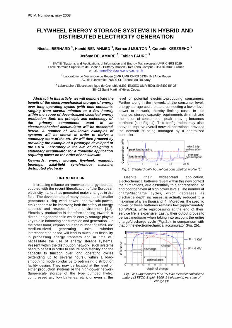
level of potential electricity-producing consumers. Further along in the network, at the consumer level, energy storage could enable connecting a lower level power to network, thereby limiting costs. In this instance, storage capacity requirements diminish and the notion of consumption peak shaving becomes pertinent (see Fig. 1). This configuration may also serve to improve overall network operations, provided the network is being managed by a centralized controller.
Fig. 1: Standard daily household consumption profile [3]
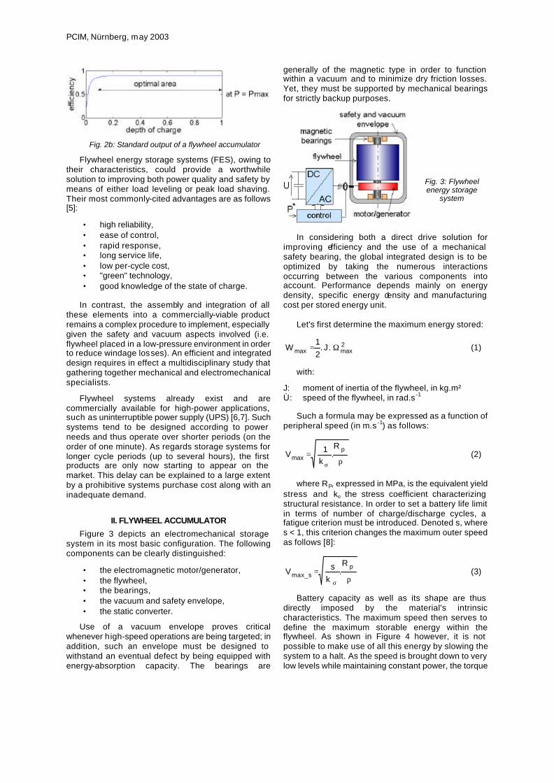
Despite their widespread application, electrochemical batteries reveal within this new context their limitations, due essentially to a short service life and poor behavior at high power levels. The number of charge/discharge cycles, which decreases as discharge depth increases, is actually reduced to a maximum of a few thousand [4]. Moreover, the specific power of these batteries remains low (approximately 10 Wh/kg), while reprocessing at the end of their service life is expensive. Lastly, their output proves to be just mediocre when taking into account the entire charge/discharge cycle (Fig. 2a), in comparison with that of the electromechanical accumulator (Fig. 2b).
Fig. 2a: Output curves for a 15-kWh electrochemical lead battery (STECO Saphir 3600, 24 elements) vs. state of
charge [3]
PCIM, Nürnberg, may 2003
Fig. 2b: Standard output of a flywheel accumulator Flywheel energy storage systems (FES), owing to
their characteristics, could provide a worthwhile solution to improving both power quality and safety by means of either load leveling or peak load shaving. Their most commonly-cited advantages are as follows [5]:
• high reliability, • ease of control, • rapid response, • long service life, • low per-cycle cost, • "green" technology, • good knowledge of the state of charge.
In contrast, the assembly and integration of all
these elements into a commercially-viable product remains a complex procedure to implement, especially given the safety and vacuum aspects involved (i.e. flywheel placed in a low-pressure environment in order to reduce windage losses). An efficient and integrated design requires in effect a multidisciplinary study that gathering together mechanical and electromechanical specialists.
Flywheel systems already exist and are commercially available for high-power applications, such as uninterruptible power supply (UPS) [6,7]. Such systems tend to be designed according to power needs and thus operate over shorter periods (on the order of one minute). As regards storage systems for longer cycle periods (up to several hours), the first products are only now starting to appear on the market. This delay can be explained to a large extent by a prohibitive systems purchase cost along with an inadequate demand.
II. FLYWHEEL ACCUMULATOR
Figure 3 depicts an electromechanical storage system in its most basic configuration. The following components can be clearly distinguished:
• the electromagnetic motor/generator, • the flywheel, • the bearings, • the vacuum and safety envelope, • the static converter.
Use of a vacuum envelope proves critical
whenever high-speed operations are being targeted; in addition, such an envelope must be designed to withstand an eventual defect by being equipped with energy-absorption capacity. The bearings are
generally of the magnetic type in order to function within a vacuum and to minimize dry friction losses. Yet, they must be supported by mechanical bearings for strictly backup purposes.
Fig. 3: Flywheel energy storage
system
In considering both a direct drive solution for
improving efficiency and the use of a mechanical safety bearing, the global integrated design is to be optimized by taking the numerous interactions occurring between the various components into account. Performance depends mainly on energy density, specific energy density and manufacturing cost per stored energy unit.
Let's first determine the maximum energy stored:
2maxmax . J .
21
W Ω= (1)
with:
J: moment of inertia of the flywheel, in kg.m² Ù: speed of the flywheel, in rad.s -1
Such a formula may be expressed as a function of
peripheral speed (in m.s -1) as follows:
ρ=
σ
pmax
R.
k1V (2)
where Rp, expressed in MPa, is the equivalent yield
stress and kσ the stress coefficient characterizing structural resistance. In order to set a battery life limit in terms of number of charge/discharge cycles, a fatigue criterion must be introduced. Denoted s, where s < 1, this criterion changes the maximum outer speed as follows [8]:
ρ=
σ
psmax_
R.
ksV (3)
Battery capacity as well as its shape are thus
directly imposed by the material's intrinsic characteristics. The maximum speed then serves to define the maximum storable energy within the flywheel. As shown in Figure 4 however, it is not possible to make use of all this energy by slowing the system to a halt. As the speed is brought down to very low levels while maintaining constant power, the torque

PCIM, Nürnberg, may 2003
of the motor/generator that actually performs the energy conversion becomes increasingly high.
By denoting r as the following ratio:
min
max
V
Vr= (4)
the useful energy Wu capable of being extracted
from the system (not including losses in the motor/generator) can then be written as:
2
2
maxur
1r.WW
−= (5)
An r = 3 ratio value, with system discharge depth set at 89%, would appear to offer a good compromise between the size of the operating range at maximum constant power for the motor/generator and maximum usable energy.
0,890,990,99
0,00,20,40,60,81,01,2
1 3 5 7 9
r
Wu/
Wm
ax
Fig. 4: Evolution in useful energy vs. r
The characteristics discussed above basically reflect the vantage point of the mechanics specialist, who considers energy to be the determinant dimensional data element. The electrical engineer, on the other hand, tends to rely upon power and torque in designing the electromechanical converter. Consequently, the ratio of motor-to-wheel volumes depends on the particular application (see Fig. 5). Over long-term cycling (i.e. load leveling and peak load shaving), wheel volume accounts for the major share of accumulator volume, which implies a situation of energy-based design. In contrast, for UPS-type applications, the wheel is small in size compared to the motor/generator: This situation implies a power-based design, whereby the rotor alone may actually constitute the flywheel.
Fig. 5: Long- and short-
term storage (energy accumulator on
the left, power accumulator on the
right)
The flywheel:
The compromise sought between accumulator performance and cost depends on the choice of material used in building the flywheel.
Material
Designation
Density
(kg/dm3)
Yield strength
(MPa)
Base material
price (€/kg)
High-strength steel
36 NiCrMo16 7.8 880 3
Titanium TA6V 4.42 1,950 30 Aluminum 2017 2.79 280 4.5 Composites E glass - epoxy 2.04 1,400 7.5
Table 1: Material data [9]
The specific energy density and energy density of
the flywheel alone are expressed as follows [9]:
ρ
σ= max
m .KMW (6)
max.KW
σ=ϑ ϑ (7)
The factors Km and Kυ depend on the wheel shape (Km = Kυ = 0.6 for a solid cylinder). According to these relations, the energy-related performance is primarily imposed via parameters Km, Kυ, σmax and ρ. The figure below presents three types of flywheel-motor/generator systems architecture. For each existing shape, factors km and kv display unique values [10,11].
Solid cylinder Hollow cylinder Constant
stress disc
Table 2: Basic system structures: flywheel and integrated motor/generator [9]
Fig. 6: Evolution in the values of both the mass energy coefficient (Km) and the volumic energy coefficient (Kv) for a
cylinder [9]

PCIM, Nürnberg, may 2003
Cost estimations, conducted by the American company Beacon Power, have served to distinguish two types of families, depending on the level of stored energy. For energy quantities less than a threshold of between 2 and 6 kWh, steel would seem to be a preferable material. Above this threshold, it becomes more attractive to use composite materials, in particular those with a carbon fiber base [12].
Motor/generator:
The necessity of introducing high speeds imposes certain constraints in the production of a motor/generator assembly. Windings and rotating contacts (brushes, etc.) are to be avoided, while the rotor must remain robust. Moreover, the operating range at maximum constant power must be as broad as possible (e.g. a ratio value of 3).
Good candidates for this purpose may be found among induction machines, switched reluctance devices or permanent magnet synchronous machines. Synchronous machines with a stator-wound inductor do however display the following advantages:
ð possibility of controlled dropout over a broad operating range at maximum constant power;
ð possibility of effectively optimizing energy output (minimization of both Joule losses and magnetic losses);
ð operability without magnetic losses in no load operation;
ð high level of design flexibility, hence easily-integrated.
Furthermore, it should be pointed out that in light of
research advances over the past thirty years, the proposed solutions are converging towards a synchronous motorization with both armature and field windings fixed in the airgap creating a homopolar flux; such a configuration proves favorable for reducing magnetic losses and for minimizing vibrations and acoustical noise.
For illustration purposes, two patent application examples (Figs. 7 and 8), featuring radial-field and axial-field structures of the synchronous type with fixed homopolar excitation, are presented below. On the structure displayed in Figure 7 (Clifton [13]), the outer part of the flywheel has been placed between two magnetic yoke frames containing the field and armature windings. The armature winding is made of litz wire in order to minimize magnetic losses.
Fig. 7: Structure corresponding to the patent application filed in 1999 by Clifton [13]
More recently, a structure composed of both field and armature windings fixed within the airgap [14] has been proposed. The stator comprises two rings consisting of spiral-coiled strips to limit magnetic losses. The armature winding is positioned on the outer ring and assumes the shape of a Gramme armature.
Fig. 8: Patent application filed in 2001 by Tupper [14] Bearings:
The simple and economical solution that calls for using just ball bearings cannot be envisaged in the majority of cases, given the constraints inherent in electromechanical storage. The need for high-speed operations, coupled with a lack of ensured centering and the exclusion of a lubricator for vacuum systems, does not as such enable guaranteeing a satisfactory level of performance and reliability.
The solution currently implemented within several systems consists of utilizing bearings that are either purely magnetic or hybrid, i.e. associating magnets for sustentation with ball bearings for guidance.
Magnetic bearings allow for free rotation of the
entire assembly around the principal axis of inertia and serve to minimize both friction and vibrations, which are sources of losses and noise. Moreover, they must ensure sustentation and centering.
The completely-passive solution (simple and inexpensive) would only use magnet-mounted assemblies and ferromagnetic circuits in performing these two functions would lead, according to Earnshaw's theorem [15], to a mode of operations incapable of being stabilized.
Fig. 9: Example of an active
centering device
(4-winding supply + 4 position sensors +
regulators)
On the other hand, the completely-active solution
(active means that all rotation and translation

PCIM, Nürnberg, may 2003
movements must be controlled), implemented exclusively with electromagnets (see Fig. 9), would provide for optimal control and engender high stiffness values, thereby accommodating high-speed operations. This solution however remains costly.
A semi-active, hybrid bearing solution would enable
striking a good compromise that combines simplicity, limited cost and low consumption [16,17]. In using this type of bearing, for example, an active radial position gets associated with a passive axial position obtained via the reluctant effect (Fig. 10).
Fig. 10: Example of a variable-reluctance
centering device
While this solution proves attractive by virtue of its
simplicity, the stiffness values obtained remain small, which introduces low-resonance frequencies into the system.
For systems where both the targeted sustained
masses and stiffnesses are sizable, the approach adopted calls for use of supra-conducting magnetic bearings with high critical temperature [18,19]. This cryogenic technology however is still in the experimental stages. Control:
A general control diagram has been depicted in Fig. 11 below.
SM
J
ine rtial
lo ad
DC
AC
Udc
Cu rrent
regu lator Pow er
re feren ce*
I * P* Pow er
contr ollerPWM
If *
,θ Ω
Fig. 11: General control diagram
Variable-speed synchronous machines are almost
always used nowadays in the commutation mode in order to prevent against any risk of stalling. In the particular case of the flywheel accumulator, characterized by high speed and high inertia, a high dynamic performance is not required. A single impulse per rotation sensor thus becomes possible. This solution is suitable and easy to implement and has already been proposed in [20]. The position can then be accurately extrapolated for high speeds and low accelerations. With one impulse, the angle error, at a given acceleration γ and given speed Ω0, is expressed as follows:
Ω−πγ+Ω
Ω+πγ−Ω
γπ=θ∆ 0
200
20 44
21
-2p
(8)
with p representing the number of pole pairs. Fig. 12 shows the angle error for two different standard accelerations. Over the speed range between 10,000 and 30,000 rpm, this error can be considered negligible. Such a control would then be entirely suitable.
00,001
0,0020,003
0,004
0,0050,006
0 10000 20000 30000 40000
speed (rpm)
angl
e er
ror
(°)
0,54 rd/s² 0,27 rd/s²
Fig. 12: Angle error with two different accelerations
An electromechanical energy accumulator is
controlled since a power command; a simple regulation loop that relies upon a corrector of the proportional-integral type [21], with current being controlled solely on the q axis, could be envisaged. Nonetheless, the ensuing operations (with id = 0) minimize only the Joule losses of the armature winding, which is not sufficient for the purposes of our application. At higher speeds, magnetic losses (eddy currents created inside the armature winding) actually become significant. It will thus be necessary to seek operations that minimize total losses by means of simultaneous action carried out on the three control parameter quantities (Fig. 13).
Fig. 13:
Control aimed at minimizing losses The benefit of the flux weakening combining both
action on the angle ψ and action on the excitation current If [22] has been demonstrated. A trio of optimal values, which depend on the particular operating point, is thereby obtained.
This theory however does not directly provide a solution to the task of instituting power control. As regards operating at minimal losses, two techniques nowadays are proposed.
The first, which stems from research conducted on the control of DC machines, consists of minimizing this power by acting on the control variables [23] through reliance upon DC bus power measurements. This

PCIM, Nürnberg, may 2003
method offers the advantage of not being influenced by variations in machine parameters, e.g. armature resistance. On the other hand, it serves as a source of instability and is capable of producing coupling oscillations when the dynamics sought lie at higher levels.
The second method consists of applying, on the basis of current and speed measurements, optimal control parameter quantities in light of the loss model. The control parameters are then generated by means of either computation ([24],[25],[26],[27]) or use of a data table. However, computation time is longer and neglected variations in machine parameters (e.g. temperature) could yield significant errors.
III. EXISTING SYSTEMS
A few American companies are currently leaders in the market. Active Power [6] and Piller [7] are manufacturing relatively slow-steel flywheels, mainly dedicated for UPS applications.
Fig. 14: The Active Power system 62.5 kW and 2.7 kWh - 7,700 rpm
330 kg
The other companies, Beacon Power [12], Urenco [28], Acumentric [29] and AFS-Trinity [30], tend to use high-speed composite materials (see Figs. 15-17).
Fig. 15: The Beacon Power Systems product
6 kWh and 2 kW - 22,500 rpm height: 120 cm, diameter: 68 cm,
mass: 800 kg underground installation
The American company Beacon Power is, to the
best of our knowledge and for the time being, the only manufacturer on the market to propose a line of high-energy high-performance systems (long cycles); these products rely upon carbon and fiberglass composite wheels with synchronous motorization and magnetic bearings. The accumulator presented in Fig. 15 is guaranteed for a 20-year service life.
The Urenco Company manufactures high-power systems (see Fig. 16) whose high-speed fiberglass wheels are sustained by the introduction of frictionless bearings based on gas centrifuge technology. These systems were recently installed for experimentation by supplying substations in the London Underground transit system (300 kW already installed). Within this context of electric vehicle traction, whereby consumption peaks during both startup and braking phases constitute major system constraints, storage components are becoming more widely envisaged in efforts to minimize installation space and cost requirements.
Fig. 16: The Urenco system 100 kW and 5 kWh - 42,000 rpm
total mass: 1,600 kg 1.6 m x 1.6 m x 0.9 m
10 million cycles (20-year design life)
At present, AFS-Trinity is working on 100 kW pre-production units that the company expects to begin shipping to strategic customer/distributors in early 2004.
Fig. 17:
The AFS-Trinity system 200 kW - 2 kWh
mass: 540 kg 40,000 rpm
100,000 cycles
IV. A LONG-CYCLE, LOW-COST ENERGY
STORAGE PROTOTYPE
A relatively low-cost and high-energy density solution has been investigated in our laboratory. For a stationary application, cost, reliability and operating safety were selected as the lead criteria. At the present time, only the systems designed on the basis of these criteria may be marketed in competition with more conventional storage systems (e.g. electrochemical batteries).
The prototype presented in this article has been designed from this perspective (its final layout has been established to accumulate 3 kWh of energy for 3-kW maximum power). Built in order to validate both the technological choices and the integration of the various

PCIM, Nürnberg, may 2003
structural components, this prototype enables studying a number of different configurations: ball bearing- or magnetic bearing-based rotor guidance, modifications to the motor-generator rotor. Its main physical characteristics are listed below:
Mass (wheel + discs) 29 kg Inertia 0.14 kg.m² Wheel diameter 0.2 m Maximum energy 250 W-h Maximum speed 20,000 rpm
Table 3: Primary data on the prototype developed
In the case of a stationary application, weight and volume represent secondary constraints. The choice of a solid cylinder made of steel manufactured in 35NiCrMo16 offers a good compromise between material and manufacturing process costs and efficiency (see Table 3). In addition, such a material, due to its magnetic properties, easily leads to generating an integrated design of both the motor/generator and the magnetic bearings. The manufacturing process, which is scaled-down, then proves simpler to implement and thereby increases reliability.
The design stage also incorporates the effects of fatigue induced by the charge/discharge cycles. As for the prototype, the maximum stress is 80 MPa, which yields a sufficient safety factor.
Fig. 18a: View of the completed structure
(not including the vacuum envelope)
Fig. 18b: View of the wheel along with the integrated
motor/generator rotor Mass: 30 kg
Magnetic bearings:
A hybrid solution involving semi-active bearings,
which strikes a good compromise combining simplicity, reduced cost and low consumption, has been developed [16]. In this structure (see Fig. 19), the flywheel is sustained by magnets in the form of rings (axial magnetization) and maintained around an unstable equilibrium position by a winding set at zero current, resulting in low consumption in the absence of perturbation. Centering is then conducted passively thanks to the reluctant effect with the help of concentric grooves (see Fig. 19), machined at both the rotor and stator. This solution however has shown some instabilities due to induced currents.
Fig. 19: The semi-active bearings studied (upper half-element)
The motor/generator:
The machine presented herein (see Figs. 20-23) is
an integrated synchronous motor/generator (see the Appendix for geometric dimensions). It represents a new integrated topology [31] and has been specifically designed for flywheel energy storage. The use of solid steel discs without any magnets or windings would appear mandatory due to the high speed required for this application. Furthermore, when a vacuum system is used, the behavior of brushes is poor, even with DC current and heat transfer since the rotor is limited by conduction through the brushes.
The field coil fed by a DC current creates a homopolar flux in the airgap and magnetizes the solid steel discs. The rotation creates a rotative axial field. The torque is generated by interaction between this field and the rotating field produced by the three-phase armature winding.
Fig. 20: Overview of the homopolar
axial synchronous
motor/generator
The steel discs, whose number of teeth equals the number of pole pairs, are submitted to mechanical stresses and have thus been studied for geometrical optimization (Fig. 21).
Fig. 21: Distribution of the stresses on a half-tooth computed using finite elements (tooth opening = 45°)
PCIM, Nürnberg, may 2003
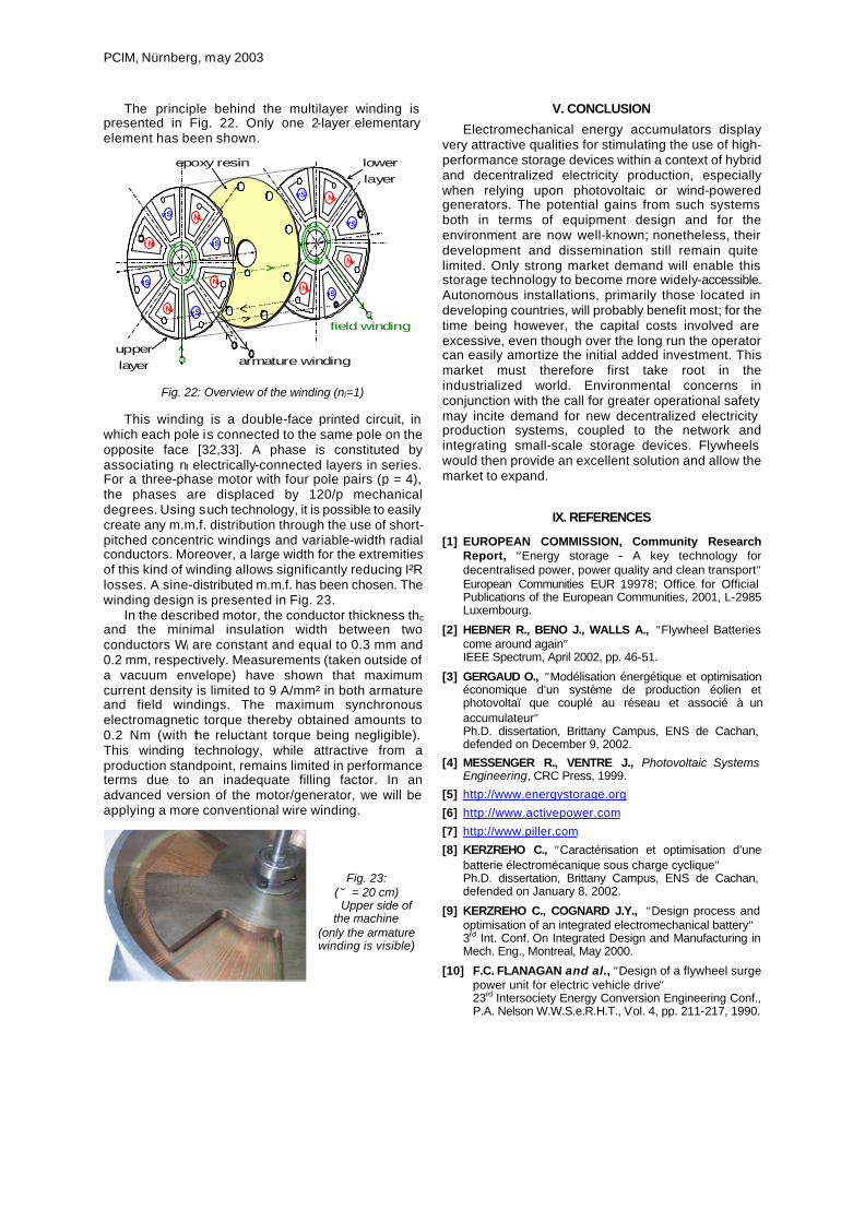
The principle behind the multilayer winding is presented in Fig. 22. Only one 2-layer elementary element has been shown.
N
S
S
NS
N
S
N
epoxy resin
N
S
S
SN
N S
N
lowerlayer
armature winding
field winding
upperlayer
Fig. 22: Overview of the winding (nl=1)
This winding is a double-face printed circuit, in which each pole is connected to the same pole on the opposite face [32,33]. A phase is constituted by associating nl electrically-connected layers in series. For a three-phase motor with four pole pairs (p = 4), the phases are displaced by 120/p mechanical degrees. Using such technology, it is possible to easily create any m.m.f. distribution through the use of short-pitched concentric windings and variable-width radial conductors. Moreover, a large width for the extremities of this kind of winding allows significantly reducing I²R losses. A sine-distributed m.m.f. has been chosen. The winding design is presented in Fig. 23.
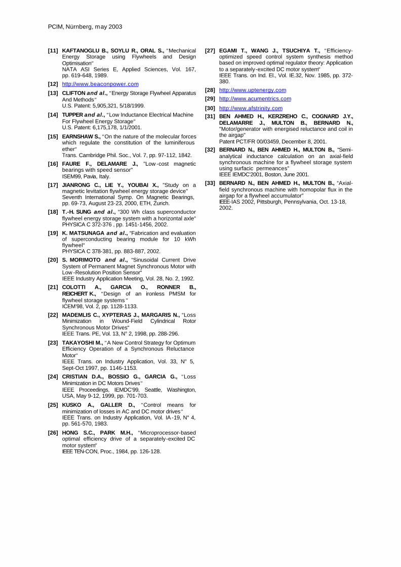
In the described motor, the conductor thickness thc and the minimal insulation width between two conductors Wi are constant and equal to 0.3 mm and 0.2 mm, respectively. Measurements (taken outside of a vacuum envelope) have shown that maximum current density is limited to 9 A/mm² in both armature and field windings. The maximum synchronous electromagnetic torque thereby obtained amounts to 0.2 Nm (with the reluctant torque being negligible). This winding technology, while attractive from a production standpoint, remains limited in performance terms due to an inadequate filling factor. In an advanced version of the motor/generator, we will be applying a more conventional wire winding.
Fig. 23: (∅ = 20 cm) Upper side of
the machine (only the armature winding is visible)
V. CONCLUSION
Electromechanical energy accumulators display very attractive qualities for stimulating the use of high-performance storage devices within a context of hybrid and decentralized electricity production, especially when relying upon photovoltaic or wind-powered generators. The potential gains from such systems both in terms of equipment design and for the environment are now well-known; nonetheless, their development and dissemination still remain quite limited. Only strong market demand will enable this storage technology to become more widely-accessible. Autonomous installations, primarily those located in developing countries, will probably benefit most; for the time being however, the capital costs involved are excessive, even though over the long run the operator can easily amortize the initial added investment. This market must therefore first take root in the industrialized world. Environmental concerns in conjunction with the call for greater operational safety may incite demand for new decentralized electricity production systems, coupled to the network and integrating small-scale storage devices. Flywheels would then provide an excellent solution and allow the market to expand.
IX. REFERENCES
[1] EUROPEAN COMMISSION, Community Research Report, ″Energy storage - A key technology for decentralised power, power quality and clean transport″ European Communities EUR 19978; Office for Official Publications of the European Communities, 2001, L-2985 Luxembourg.
[2] HEBNER R., BENO J., WALLS A., ″Flywheel Batteries come around again″ IEEE Spectrum, April 2002, pp. 46-51.
[3] GERGAUD O., ″Modélisation énergétique et optimisation économique d’un système de production éolien et photovoltaï que couplé au réseau et associé à un accumulateur″ Ph.D. dissertation, Brittany Campus, ENS de Cachan, defended on December 9, 2002.
[4] MESSENGER R., VENTRE J., Photovoltaic Systems Engineering, CRC Press, 1999.
[5] http://www.energystorage.org
[6] http://www.activepower.com
[7] http://www.piller.com
[8] KERZREHO C., ″Caractérisation et optimisation d’une batterie électromécanique sous charge cyclique″ Ph.D. dissertation, Brittany Campus, ENS de Cachan, defended on January 8, 2002.
[9] KERZREHO C., COGNARD J.Y., ″Design process and optimisation of an integrated electromechanical battery″ 3rd Int. Conf. On Integrated Design and Manufacturing in Mech. Eng., Montreal, May 2000.
[10] F.C. FLANAGAN and al., ″Design of a flywheel surge power unit for electric vehicle drive″
23rd Intersociety Energy Conversion Engineering Conf., P.A. Nelson W.W.S.e.R.H.T., Vol. 4, pp. 211-217, 1990.
PCIM, Nürnberg, may 2003
[11] KAFTANOGLU B., SOYLU R., ORAL S., ″Mechanical Energy Storage using Flywheels and Design Optimisation″
NATA ASI Series E, Applied Sciences, Vol. 167, pp. 619-648, 1989.
[12] http://www.beaconpower.com
[13] CLIFTON and al., ″Energy Storage Flywheel Apparatus And Methods″
U.S. Patent: 5,905,321, 5/18/1999.
[14] TUPPER and al., ″Low Inductance Electrical Machine For Flywheel Energy Storage″
U.S. Patent: 6,175,178, 1/1/2001.
[15] EARNSHAW S., ″On the nature of the molecular forces which regulate the constitution of the luminiferous ether″
Trans. Cambridge Phil. Soc., Vol. 7, pp. 97-112, 1842.
[16] FAURE F., DELAMARE J., "Low -cost magnetic bearings with speed sensor"
ISEM99, Pavia, Italy.
[17] JIANRONG C., LIE Y., YOUBAI X., "Study on a magnetic levitation flywheel energy storage device"
Seventh International Symp. On Magnetic Bearings, pp. 69-73, August 23-23, 2000, ETH, Zurich.
[18] T.-H. SUNG and al., “300 Wh class superconductor flywheel energy storage system with a horizontal axle“
PHYSICA C 372-376 , pp. 1451-1456, 2002.
[19] K. MATSUNAGA and al., “Fabrication and evaluation of superconducting bearing module for 10 kWh flywheel“
PHYSICA C 378-381, pp. 883-887, 2002.
[20] S. MORIMOTO and al., “Sinusoidal Current Drive System of Permanent Magnet Synchronous Motor with Low -Resolution Position Sensor“
IEEE Industry Application Meeting, Vol. 28, No. 2, 1992.
[21] COLOTTI A., GARCIA O., RONNER B., REICHERT K., ″Design of an ironless PMSM for flywheel storage systems ″
ICEM’98, Vol. 2, pp. 1128-1133.
[22] MADEMLIS C., XYPTERAS J., MARGARIS N., “Loss Minimization in Wound-Field Cylindrical Rotor Synchronous Motor Drives“
IEEE Trans. PE, Vol. 13, N° 2, 1998, pp. 288-296.
[23] TAKAYOSHI M., ″A New Control Strategy for Optimum Efficiency Operation of a Synchronous Reluctance Motor″
IEEE Trans. on Industry Application, Vol. 33, N° 5, Sept-Oct 1997, pp. 1146-1153.
[24] CRISTIAN D.A., BOSSIO G., GARCIA G., ″Loss Minimization in DC Motors Drives″
IEEE Proceedings, IEMDC’99, Seattle, Washington, USA, May 9-12, 1999, pp. 701-703.
[25] KUSKO A., GALLER D., ″Control means for minimization of losses in AC and DC motor drives″
IEEE Trans. on Industry Application, Vol. IA -19, N° 4, pp. 561-570, 1983.
[26] HONG S.C., PARK M.H., ″Microprocessor-based optimal efficiency drive of a separately-excited DC motor system″
IEEE TEN-CON, Proc., 1984, pp. 126-128.
[27] EGAMI T., WANG J., TSUCHIYA T., ″Efficiency-optimized speed control system synthesis method based on improved optimal regulator theory: Application to a separately-excited DC motor system″
IEEE Trans. on Ind. El., Vol. IE.32, Nov. 1985, pp. 372-380.
[28] http://www.uptenergy.com
[29] http://www.acumentrics.com
[30] http://www.afstrinity.com
[31] BEN AHMED H., KERZREHO C., COGNARD J.Y., DELAMARRE J., MULTON B., BERNARD N., "Motor/generator with energised reluctance and coil in the airgap"
Patent PCT/FR 00/03459, December 8, 2001.
[32] BERNARD N., BEN AHMED H., MULTON B., “Semi-analytical inductance calculation on an axial-field synchronous machine for a flywheel storage system using surfacic permeances”
IEEE IEMDC’2001, Boston, June 2001.
[33] BERNARD N., BEN AHMED H., MULTON B., “Axial-field synchronous machine with homopolar flux in the airgap for a flywheel accumulator”
IEEE-IAS 2002, Pittsburgh, Pennsylvania, Oct. 13-18, 2002.