
Flyin’ Miata ECU installation instructions for ‘96 & ‘97 ... · Flyin’ Miata ECU...
13
Flyin’ Miata ECU installation instructions for ‘96 & ‘97 Miatas Revision .6 2-3-05
Transcript of Flyin’ Miata ECU installation instructions for ‘96 & ‘97 ... · Flyin’ Miata ECU...
�
Flyin’ Miata ECU installationinstructions for ‘96 & ‘97 Miatas
Revision �.6�2-�3-05

2
ContentsSection �: Introduction ..........................................................................3Section 2: Mounting the FM ECU .........................................................4 Wide Band O2 Sensor (optional) .........................................4Section 3: Air Temperature Sensor .......................................................5Section 4: Fuel Injectors ......................................................................8Section 5: MAP Sensor ........................................................................9Section 6: Knock Sensor ....................................................................�0Section 7: Boost Control Solenoid ...................................................... ��Appendix A: .........................................................................................�3

3
Section 1: Introduction
The FM ECU completely replaces the factory Engine Control Unit (ECU) to take full control of the engine’s functions. The ECU fits into the factory ECU case and plugs into the factory ECU harness. The only wire splicing required for this ECU is to use the boost control solenoid to control turbo boost pressure.
For this wire splicing, we recommend, and include, heat shrinkable crimp connectors. A crimp connection is better both structurally and electrically than a solder connection. If you do not believe us, try to find one soldered connection in the entire wire harness in your Miata. The integrity of a crimp connection depends on the quality of the tools used for the installation. Go to Sears and invest in a high quality pair of wire crimping pliers. These can be bought for $25 to $30, and will quickly pay for themselves in this and future projects.
The included crimp connectors use a heat shrinkable coating. Once the wires are crimped in place, heat the connector with a heat gun (buy one of these at Sears with your crimping tool) to shrink down the outer covering. This will provide a water tight seal for the life of your car.
4
Section 2: Mounting the FM ECU
The factory ECU is found under the carpet behind the passenger seat.
Note: For European cars only! When fitting this ECU to a U.K. MX-5 please refer to Ap-pendix A before installation.
�) Disconnect the negative terminal on the battery.
2) Slide the passenger seat all the way forward the pull up the carpet behind the seat. The ECU is bolted to the rear bulkhead.
3) Remove the wire harness by pressing down on the tabs in the center of the connectors and pulling down on the plug. The ECU can now be removed from the car.
4) Take the ECU to a workbench where it can be worked on. Remove the phillips screws that hold the mounting brackets to the case as needed.
5) Remove the 4 phillips head screws holding the steel plate to the bottom of the ECU case. Remove the � phillips head screw that secures the ECU circuit board to the case.
6) Before mounting the new FM ECU a slot or hole must be made in the aluminum case to allow the ribbon cable to pass through. Make sure the opening has no sharp edges that could cut through the ribbon cable.
7) Plug one end of the ribbon cable in to the keypad and the other end into the ECU socket. Mount the FM ECU into the factory case. Put the steel cover back on the bottom side.
8) Mount the ECU back in the car and plug in the wire harness connectors.
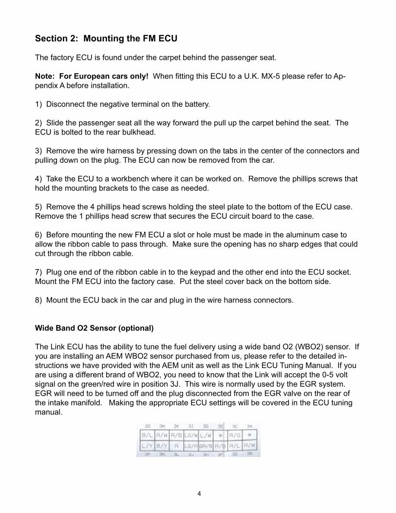
Wide Band O2 Sensor (optional)
The Link ECU has the ability to tune the fuel delivery using a wide band O2 (WBO2) sensor. If you are installing an AEM WBO2 sensor purchased from us, please refer to the detailed in-structions we have provided with the AEM unit as well as the Link ECU Tuning Manual. If you are using a different brand of WBO2, you need to know that the Link will accept the 0-5 volt signal on the green/red wire in position 3J. This wire is normally used by the EGR system. EGR will need to be turned off and the plug disconnected from the EGR valve on the rear of the intake manifold. Making the appropriate ECU settings will be covered in the ECU tuning manual.

5
Section 3: Air Temperature Sensor
Turbocharged Cars
NOTE: The intake air temperature sensor is a required part of the ECU and its function. The sensor must be installed properly in order for the ECU to function.
1) On FM turbo kits the temperature sensor fits inside the boss on the throttle inlet pipe. New turbo kits will have a slot machined in this part from the factory. On existing kits cut a �/�6" wide �/4" deep slot vertically in the boss as shown in the photos.
2) Take off the rubber hose that connects the IAC valve to the throttle body inlet pipe and drill a �/8” diameter hole in the side for the two wires from the air temperature sensor to come through.
3) On the air temperature sensor, tie both wires together in a single knot about 2" from the sensor board. Run the wires out of the hole in the IAC hose. Pull them through the hole until the knot stops the wires from going any farther.
4) Slide the air temperature sensor into the boss on the throttle body inlet pipe all the way down so that the ears on the board bottom in the two slots on the boss. Then slide the IAC hose over the top of the boss.
5) Secure the hose on the boss with a hose clamp. Seal the hole in the IAC hose with a small dab of silicone sealant.
6) Mount the throttle body pipe back on the car.

6
7) Cut the tinned ends off the wires on the air temperature sensor. Crimp the ring terminal to the black wire on the temperature sensor and connect it under the 6mm nut that holds a few other grounds to a bracket just below and inboard of the throttle body. (See photo on the previ-ous page.)
8) Crimp the bullet connector to the white wire.
9) On the top of the power steering pump is a Blue/Yellow wire. Pull this wire off the power steering pump by pulling it straight up. Connect the white wire from the air temperature sensor to the female bullet connector on this wire.
10) If the car is not fitted with power steering the Blue/Yellow wire may be tied off to the breather line behind the thermostat housing. Connect the white wire from the air temperature sensor to the female bullet connector on this wire.
��) If the Blue/Yellow wire is not in the wire harness a new wire will need to be run from the intake air temperature sensor to terminal 3P on the ECU. Contact FM for a metal terminal to insert the wire into the plastic plug.
Supercharged Cars
Warning: The intake air temperature sensor can only be used in the following location (after the blower) if the system uses an intercooler or water injection. On non-inter-cooled systems the temperature sensor must be mounted before the blower because the air exiting the blower will exceed 100*C and trigger the ECU’s intake over tempera-ture limit.
The intake air temperature sensor is a required part of the ECU and its function. The sensor must be installed properly in order for the ECU to function. In JR supercharged installations the air temperature sensor can be mounted in the dummy throttle body on the intake manifold as long as an intercooler is used.
�) Remove the dummy throttle body from the motor.
2) Drill a �/2” diameter hole in the dummy throttle body as shown in the photo on the next page. Drill two holes in the side of the body for the wires to go through.
3) Mount the intake air temperature sensor in the hole and run the wires out the two small holes. Secure the sensor in place with a small dab of silicone sealant.
4) Mount the dummy throttle body pipe back on the car.
5) Cut the tinned ends off the wires on the air temperature sensor. Crimp the ring terminal to the black wire on the temperature sensor and connect it under the 6mm nut that holds a few other grounds to a bracket just below and inboard of the throttle body.
6) Crimp the bullet connector to the white wire.

7
7) On the top of the power steering pump is a Blue/Yellow wire. Pull this wire off the power steering pump by pulling it straight up. Connect the white wire from the air temperature sensor to the female bullet connector on this wire.
8) If the car is not fitted with power steering the Blue/Yellow wire may be tied off to the breather line behind the thermostat housing. Connect the white wire from the air temperature sensor to the female bullet connector on this wire.
9) If the Blue/Yellow wire is not in the wire harness a new wire will need to be run from the intake air temperature sensor to terminal 3P on the ECU. Contact FM for a metal terminal to insert the wire into the plastic plug.
Normally Aspirated Cars
Since the intake system on a normally aspirated cars can vary greatly and there is no com-pression of the intake charge, the intake air temperature sensor can be mounted almost any where. For example, if an open element air filter is used, the sensor can be secured to the outer surface of the filter with a zip tie. On systems using the factory plastic cross over pipe, the sensor can be mounted somewhere in the pipe. Just make sure the sensor does not move or vibrate. It must be held securely in place.
Follow the wiring instructions for either the supercharger or turbocharger section.

8
Section 4: Fuel Injectors
This section covers replacing the stock fuel injectors with the PL550cc (low impedance) fuel injectors included in the FMII kit for boosted operation. This ECU has low impedance injector drivers. On normally aspirated installations the stock injectors will be used, so skip this section.
�) Remove the gas cap to relieve pressure in the fuel tank.
2) Unplug the electrical connectors for the fuel injectors.
3) The RC fuel injectors, provided by FM, use a different connectors than stock. Take the four new fuel injector connectors supplied with the fuel injectors and cut the wires down to 2” in length. We include enough spade connectors for you to keep the stock clips with the stock injectors for easy reversal if required.
4) Remove the three 8mm bolts holding the fuel rail in place. There are three black plastic spacers between the fuel rail and the head that will be loose when the bolts are removed, don’t lose them!
NOTE: Some fuel will spray out at this point so have a disposable towel ready and do NOT have a droplight nearby.
5) Once the bolts are out, wiggle the fuel rail off the injectors and pull the injectors out, being very careful not to lose the little black rings on the lower ends of the injectors. These rings will be re-used.
6) Prepare the new injectors by transferring the lower rings from the old injectors. Use a small amount of grease to make the rings slide on easier. Lubricate the o-rings at the top of the in-jector with grease as well to help them slide into the fuel rail. Be careful not to get any grease into the injectors.
7) Fit the new injectors into the holes in the cylinder head with the electrical connectors up. Slide the fuel rail down over the rubber o-rings. The o-rings fit tightly into the fuel rail, so push the fuel rail down firmly.
8) Install the 8mm bolts and the spacers to secure the fuel rail to the head.
9) Plug in the electrical connectors.

9
Section 5: MAP Sensor
The Flyin’ Miata ECU uses its own MAP (Manifold Absolute Pressure) sensor to measure the airflow so the factory mass air meter will no longer be used. On Flyin’ Miata turbo kits the pip-ing is already designed to eliminate the mass air meter. On supercharged and normally aspi-rated applications the installer will have to fabricate a pipe to take the place of the factory mass air meter. The mass air meter could be left in place, but it presents a considerable restriction to the intake air charge.
�) Plug the supplied rubber vacuum hose into the hose barb in the MAP sensor. Plug the RCA jack on the knock sensor wire into the MAP sen-sor. Plug the clip from the factory MAF sensor into the MAP sensor, with the clip side facing the sticker on the MAP sensor unit.
2) Mount the MAP sensor on the black plastic electrical cover on the driver’s inner fender by using the pro-vided double sided tape.
3) Run the vacuum hose and the knock sensor wire across the engine bay securing them to the metal vacuum line that goes to the brake booster. Let the knock sensor wire hang down on the passenger side of the engine. It will be connected in the next section.
4) The signal for the MAP sensor comes from the intake manifold. The hose to cut is shown in the photo below. It comes out of the intake manifold toward the cam cover, then turns forward to connect to the PRC valve. Cut this hose about �” from the manifold and insert the “T” fitting from the ECU.
5) Connect the vacuum hose from the MAP sensor, to the “T” fitting.

�0
Section 6: Knock Sensor
The knock sensor replaces the upper front mounting bolt on the passenger (right side) motor mount.
�) Remove the �0mm bolt in the upper forward corner of the motor mount.
2) Replace this bolt with the supplied adapter bolt and tighten to 20 ft/lbs.
3) Install the knock sensor with the supplied 8mm allen bolt. Tighten this bolt to �2 ft/lbs, using blue Locktite on the threads. PLEASE TORQUE CAREFULLY!
4) The harness for the knock sensor will be hang-ing down on this side of the engine from the pre-vious section. Plug the harness onto the knock sensor. The plug is rather tight so make certain it is fully engaged on the sensor.

��
Section 7: Boost Control Solenoid
The electrical signal for the boost solenoid will travel from the ECU through the Green/Yellow wire in the TEN terminal in the diagnostics connector. 12 volts will also be needed to power the solenoid. The air pressure signals to and from the boost control solenoid are best supplied with �/4” hose. FM turbo kits include this hose as part of the kit. If this installation is not using an FM turbo kit, get some �/4” hose for the signal lines. �) Mount the boost control solenoid to the air box as shown.
2) Open the bottom of the diagnostics con-nector to expose the wires. Cut the Green/Yellow and the White/Red wires as close to the connector as possible.
3) Using the supplied butt connectors, connect one wire from the boost control solenoid to the White/Red wire. Connect the other wire from the solenoid to the Green/Yellow wire. Use as much wire as necessary from the solenoid loom to reach the harness wires.
Note: See the diagram on the next page for the boost control hose routing.

�2
4) The boost control solenoid needs to sense the pressure created by the turbo. On our FM2 turbo kits a �/4” hose barb is mounted on the turbo for this purpose. Use the �/4" hose to con-nect the compressor barb to the EXH barb on the solenoid.
5) Connect the OUT barb on the solenoid to the wastegate actuator on the turbo using the supplied hose. The IN port on the solenoid vents to atmosphere. Leave it open.
6) Secure the connections of the hoses with zip ties. If these hoses blow off, control of the wastegate will be lost and the turbo will make enough boost to damage the engine.
The ECU installation is now complete. Refer to the ECU tuning manual to get the car up and running.

�3
Appendix A:Fuel pump wire change
On cars sold in the UK the ECU triggers the fuel pump from terminal �V. Cars sold in the U.S. (that Link used to design this ECU) trigger the fuel pump from terminal �U. The Link ECU has no circuit connection to terminal �V so the signal supplied on terminal �U must be transferred to terminal 1V. This can be done two different ways. Here are our recommendations.
�) Solder a jumper wire to the bottom of the circuit board connecting terminal �U to �V. This allows the stock wire harness to be left alone and the car returned to stock easily. To do this simply lay a solder bridge between the two pins on the bottom of the PC board. The pins are highlighted in the photo on the right.
2) Remove the �U and �V wires from the plastic plug and reverse them. This allows the ECU to remain unaltered.
Here is how the wires are moved. On the back (side that the wires go in) of the plas-tic connectors, a hinged flap on top and bottom of the connectors holds them in place. Slip a knife or thumbnail under both edges of the flaps to release them. This exposes the individual terminals.
Slip a sharp pointed tool, like a dental pick, into the back of the metal connectors above the wires that need to be moved (see picture). The tool must slide through the little loop of metal above the wire—this will release a plastic lock tab to let the connector pull out. Pull back on the tool and the wire and both will slide out the back of the plastic connector.