
Flux and torque control of switched reluctance machines
9
Flux and torque control of switched reluctance machines PG.Barrass B.C. Mecrow hidexing terms: Flux-linkage controller, Switched reluciunce muchine, Torque operution Abstract: The theory and implementation of a flux-linkage controller applied to a switched reluctance machine drive are described. Analysis of the simplified discrete time load model shows that a simple flux-linkage controller can produce a ‘dead-beat’ system response. Comparison of the response from a discrete time PID current controller, hysteresis current controller and the new flux-linkage controller, show that the flux controller has a much improved response. The experimental controller is used to control an IGBT converter, driving a commercial 7.5kW switched reluctance motor. A method of constant torque operation is introduced. This takes account of limitations imposed by the finite DC- link voltage and rotor speed when calculating the reference values. The method is b,ased on ‘flux ramps’, where the ramps are chosen to give constant shaft torque, and remain within the capabilities of the power converter. Correct selection of the flux ramps allows constant torque operation to be achieved over a wide speed and torque range. Measured results for the experimental drive demonstrate the low torque ripple achieved for motoring and generating operation over a range of speed and torque values. List of symbols D = controller gain G = plant gain H = system closed loop gain R = phase resistance T = sample interval V = phase voltage i = phase current n = sample number t = time z = discrete transfer function variable 0 IEE, 1998 IEE Proceedings online no. 19981926 Paper first received 28th August 1997 and in revised form 26th January 1998 P.G. Barrass is with Control Techniques, Newtown, Wales, UK B.C. Mecrow is with the Electric Machines and Drives Group, University of Newcastle upon Tyne, Newcastle upon Tyne, UIC CS = PWM duty cycle qj = machine phase flux-linkage 8 = rotor position co = rotor angular velocity 1 Introduction Phase current is often the controlled variable in electri- cal machine drives, so it seems natural to use closed loop current controllers. However, the highly nonlinear nature of switched reluctance machines makes optimi- sation of closed loop current controllers difficult. For voltage source converters, the directly controlled varia- ble applied to the machine is voltage, with current a function of the flux-linkage and rotor position. If the resistive voltage drop is neglected, flux-linkage is line- arly proportional to the applied volt-seconds. These considerations suggest that it may be more appropriate to design a controller based on flux-linkage, rather than current. A review of the work published on constant shaft torque operation of switched reluctance machines has revealed that the emphasis has been on low speed oper- ation using closed loop current controllers. The schemes have not generally taken account of the ability of the current controller to track the reference value. A flux-linkage controller can easily incorporate the limita- tions imposed by the DC-link voltage and rotor speed when calculating the flux reference values required for constant torque operation. 2 Current control methods The phase winding of a switched reluctance machine presents a highly nonlinear load to a current controller because the effective inductance of the phase varies with both rotor position and phase current. This has adverse implications for the two most popular types of current controller used in switched reluctance drives: hysteresis controllers and PID controllers with fixed frequency pulse width modulated (PWM) output. Hys- teresis controllers are simple to implement, uncondi- tionally stable and give a fast response to step changes. However, with a constant hysteresis band the switching frequency varies inversely with load inductance, mak- ing the trade-off of switching losses and current error band more difficult to optimise. Limits on maximum switching frequency, noise and system delays all place limits on the minimum current ripple which can be achieved. Constant switching frequency PID controllers make switching loss more controllable but it is very dif- 519 IEE Proc.-Electr. Power Appl., Vol. 145, No. 6. November 1998
Transcript of Flux and torque control of switched reluctance machines

Flux and torque control of switched reluctance machines
PG.Barrass B.C. Mecrow
hidexing terms: Flux-linkage controller, Switched reluciunce muchine, Torque operution
Abstract: The theory and implementation of a flux-linkage controller applied to a switched reluctance machine drive are described. Analysis of the simplified discrete time load model shows that a simple flux-linkage controller can produce a ‘dead-beat’ system response. Comparison of the response from a discrete time PID current controller, hysteresis current controller and the new flux-linkage controller, show that the flux controller has a much improved response. The experimental controller is used to control an IGBT converter, driving a commercial 7.5kW switched reluctance motor. A method of constant torque operation is introduced. This takes account of limitations imposed by the finite DC- link voltage and rotor speed when calculating the reference values. The method is b,ased on ‘flux ramps’, where the ramps are chosen to give constant shaft torque, and remain within the capabilities of the power converter. Correct selection of the flux ramps allows constant torque operation to be achieved over a wide speed and torque range. Measured results for the experimental drive demonstrate the low torque ripple achieved for motoring and generating operation over a range of speed and torque values.
List of symbols
D = controller gain G = plant gain H = system closed loop gain R = phase resistance T = sample interval V = phase voltage i = phase current n = sample number t = time z = discrete transfer function variable 0 IEE, 1998 IEE Proceedings online no. 19981926 Paper first received 28th August 1997 and in revised form 26th January 1998 P.G. Barrass is with Control Techniques, Newtown, Wales, UK B.C. Mecrow is with the Electric Machines and Drives Group, University of Newcastle upon Tyne, Newcastle upon Tyne, UIC
CS = PWM duty cycle qj = machine phase flux-linkage 8 = rotor position co = rotor angular velocity
1 Introduction
Phase current is often the controlled variable in electri- cal machine drives, so it seems natural to use closed loop current controllers. However, the highly nonlinear nature of switched reluctance machines makes optimi- sation of closed loop current controllers difficult. For voltage source converters, the directly controlled varia- ble applied to the machine is voltage, with current a function of the flux-linkage and rotor position. If the resistive voltage drop is neglected, flux-linkage is line- arly proportional to the applied volt-seconds. These considerations suggest that it may be more appropriate to design a controller based on flux-linkage, rather than current.
A review of the work published on constant shaft torque operation of switched reluctance machines has revealed that the emphasis has been on low speed oper- ation using closed loop current controllers. The schemes have not generally taken account of the ability of the current controller to track the reference value. A flux-linkage controller can easily incorporate the limita- tions imposed by the DC-link voltage and rotor speed when calculating the flux reference values required for constant torque operation.
2 Current control methods
The phase winding of a switched reluctance machine presents a highly nonlinear load to a current controller because the effective inductance of the phase varies with both rotor position and phase current. This has adverse implications for the two most popular types of current controller used in switched reluctance drives: hysteresis controllers and PID controllers with fixed frequency pulse width modulated (PWM) output. Hys- teresis controllers are simple to implement, uncondi- tionally stable and give a fast response to step changes. However, with a constant hysteresis band the switching frequency varies inversely with load inductance, mak- ing the trade-off of switching losses and current error band more difficult to optimise. Limits on maximum switching frequency, noise and system delays all place limits on the minimum current ripple which can be achieved. Constant switching frequency PID controllers make switching loss more controllable but it is very dif-
519 IEE Proc.-Electr. Power Appl., Vol. 145, No. 6. November 1998

ficult to optimise their time domain response. For a simple, non-adaptive controller the gains must be set such that the system is stable over the full range of sys- tem time constants. Whatever the point at which the response is optimised, the response at other points will tend to be over or under damped.
When using voltage source converters to drive electri- cal machines, the overall controlled variable is often phase current, although this is actually achieved by controlling the voltage and therefore phase flux-link- age. Thus the directly controlled machine variable is flux-linkage rather than current. For machine ratings of a few kW or more the voltage drop due to phase resistance is virtually negligible and flux-linkage is sim- ply equal to the applied volt-time integral. Phase cur- rent may be a nonlinear function of flux-linkage and time, but the flux-linkage is a linear function of voltage and time. As flux-linkage may be controlled directly, and from a control standpoint is not dependent on load nonlinearity and time constants, this suggests that superior control performance may be obtained by mak- ing flux-linkage the controlled variable.
Previous work by Lovatt [ 11 comparing a hysteresis current controller, PID current controller and flux-link- age controller showed that the flux controller per- formed better than the other types, particularly when compared over a wide dynamic range. The experimen- tal system was implemented using analogue electronics with a nonlinear inductor as a load. Flux-linkage feed- back was achieved by measuring inductor current, and estimating the flux-linkage from a three point piecewise linear approximation to the inductor characteristics.
This work extends the principles used by Lovatt by applying flux-linkage control to a rotating switched reluctance machine, rather than a fixed inductor. Lookup tables are used to estimate flux-linkage from measured phase current and rotor position, and an advanced digital controller is used to optimise the response.
3 Flux control
An ideal controller has infinite bandwidth, no delay, zero steady state error, no overshoot and maintains this response irrespective of changes in system parameters. A close approximation to this can be obtained from an auto-tuning, discrete time, dead-beat controller. This has a bandwidth of half the sample frequency, a delay
reference controller
rei, flux ref. gain limiter gain
of one sample interval and gives a unity gain step response free from overshoot or ringing.
W) D (a G(4 X(Z)
controller plant
Fig. 1 Unityfeedback system model
For the model shown in Fig. 1 to obtain a dead-beat response, the system must satisfy the following equation:
Rearrangement of eqn. 1 shows that the required con- troller characteristic is given by
1 1 Z - 1 G ( z )
D ( x ) = -. ___
For an inductive circuit with resistance R, carrying a current i, and applied voltage V, the flux-linkage is given by
t
$ ( t ) = / ( V - iR)dt (3) 0
If the resistive voltage drop is negligible compared to the applied voltage, then the discrete time transfer function for a sample interval of T using the forward difference method is:
(4)
Hence for dead-beat response the control transfer func- tion required is as follows:
1 2 - 1 1 2 - 1 G(z) 2 - 1 T T - (5) D ( z ) = -. - - -. - - - - 1 1
Thus a flux-linkage controller simply has to multiply the flux error by the sample frequency to obtain a dead-beat system response.
This shows that the controller has a very simple transfer function and forms the basis for a digital flux controlled drive. However the practical implementation has to compensate for the non-ideal nature of various parts of the system. The main departures from the ideal
motor
I
T rotor
Fig.2
.( O(t) position
position speed advance calculation
Motor flux controller transfer function block diagram
520 IEE Proc.-Electr. Power Appl., Vol. 145, No. 6, November 1998

system described above are that the flux-linkage is not measured directly, and there is a delay in the system from the sampling of variables to the application of voltage to the motor phase.
Implementation of the switched reluctance drive flux- linkage controller is shown as a transfer function block diagram in Fig. 2. This incorporates the controller, power converter, load machine and measurement blocks. In addition to the overall demand value, other parameters measured by the experimental flux-linkage controller are the phase currents, rotor position and DC-link voltage.
Flux reference values for each phase are found from lookup tables or equations which describe the reference waveshape. (Note that the reference waveshape need not be flux; current may be used instead, with the value converted into flux-linkage using the machine flux-link- agehrrent characteristics.) To help compensate for the overall system delays, the flux reference is calculated for the rotor position one step ahead. Rotor speed o is calculated from the rate of change of rotor position, and used to predict the rotor position at the next sam- ple time using the equation
where T and o are the sample interval and rotor angu- lar velocity respectively. The flux reference is then found as a function of predicted position from
The function F(0) may be implemented as an equation or lookup table.
The machine phase flux-linkage may be ascertained directly from integration of the terminal voltage, or indirectly from phase current and machine characteris- tics. The voltage integration method is prone to inte- gration drift at low speed, where the temperature variation of phase resistance can also become impor- tant, and hence the indirect method is employed. Phase current and rotor position are measured with a sample interval of T, and then the machine flux-linkagekurrent characteristics are used to determine the flux-linkage. This method requires a high resolution rotor position sensor and does not allow for any differences between static and dynamic flux-linkage characteristics. In the experimental system an absolute position sensor is used to give 10-bit resolution. The flux-linkagekurrent char- acteristics used are measured values for the machine.
It was shown in eqn. 5 that for a dead-beat response, the controller needs a transfer function of UT, so the required output voltage is given by
For the switching scheme implemented, the average output voltage over one period is proportional to the duty cycle 6 multiplied by the DC-link voltage Vdc, thus:
(9) v,* sn = - v d c
Voltage drop due to the phase winding resistance is compensated for by adding the appropriate voltage to the required output voltage. As shown in Fig. 2, the pulse width modulator gives one time sample delay between calculation of the required output voltage and application of the voltage to the phase windings.
IEE Proc.-Electr. Power AppL, Vol. 145, No. 6, November 1998
Current and rotor position are sampled at the start of the nth sample interval, and the actual flux q, is calculated. During this sample interval the applied voltage is Vn-l, so at the start of the next sample interval during which V, is actually applied, the flux will be qn plus Vn-,T. This is compensated for by subtracting the previous output voltage from the present value.
In Fig. 2 the motor is shown as a transfer function block, relating flux-linkage and rotor position to phase current. The flux-linkage lookup tables perform the inverse of this function and so the two blocks com- bined can be considered as a unity gain block in the feedback path. By representing the converter using the discrete time transfer function given in eqn. 4, and removing output limits and iR compensation, it can be shown that the forward path of the flux-linkage control loop has the following transfer function:
Closing the loop and incorporating the flux reference one step phase advance, the transfer function of the system is
(11) 1 - - -
1 T ( Z ) = Z .
(22 - 1) + 1 Z
The overall system transfer function is thus dead-beat. Computationally, the flux-controller is relatively sim- ple, involving only table lookup operations, addition and multiplication. No trigonometric or exponential functions are required. Furthermore, no tuning of gain parameters is required other than measuring the DC- link voltage.
4 Implementation
The experimental flux-linkage controlled drive system consists of a microprocessor based control system, power converter, switched reluctance test machine and DC load machine. The switched reluctance machine is a commercial three phase 12:8 design, housed in a D132 frame with a rated torque of 47". The switched reluctance machine flux-linkagehrrent char- acteristics were measured by integrating the applied voltage with the rotor mechanically locked in position. The drive is supplied from a rectified three phase sup- ply feeding a DC link capacitance of 3300pF. This large capacitance reduces the DC link voltage variation to less than 1OV. Power is supplied to the switched reluctance machine by an IGBT converter switching at lOkHz with a nominal DC-link voltage of 500V. The three phase currents are measured using Hall effect cur- rent transducers, the outputs of which are digitised using 12-bit analogue to digital converters, before being fed to the digital controller. An optical shaft encoder with a 10-bit, 1024 absolute position output is used to measure rotor angle. Most control tasks are imple- mented in software on a Texas Instruments TMS320C31 TM 32-bit floating point digital signal proc- essor (DSP). Input/output functions and PWM genera- tion are performed by a Motorola 68030TM microprocessor and TMS320E14'" DSP, with all three processors connected by a VME bus. Control software is written in assembler and C.
521
5 Experimental comparison of current and flux-
Four different phase current controllers have been implemented to compare the performance of conven- tional current controllers and the flux-linkage control- ler. Each controller is implemented digitally using the hardware described in Section 4. For all cases the con- troller sample rate and converter switching frequency is lOkHz, with a single cycle delay in the application of the demand voltage to the phase. The phase current reference is 20A for a conduction interval of 17.5 degrees of rotation, corresponding to 140 electrical degrees. At all other times the current reference is zero.
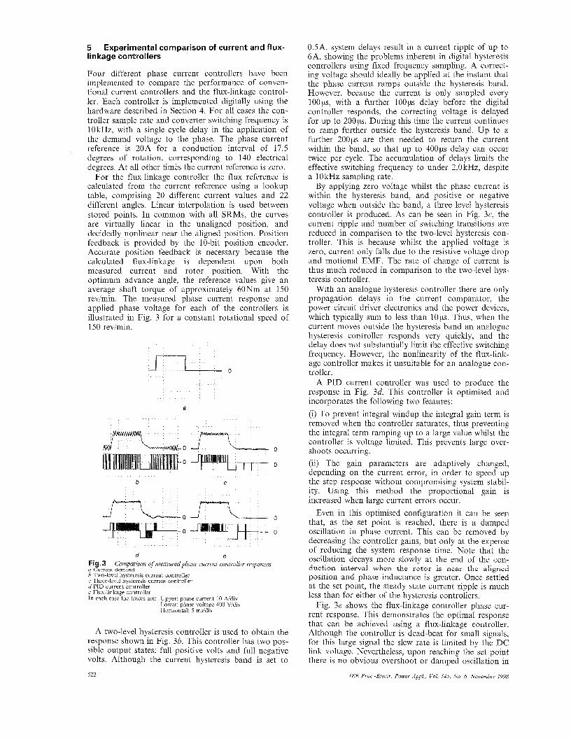
For the flux-linkage controller the flux reference is calculated from the current reference using a lookup table, comprising 20 different current values and 22 different angles. Linear interpolation is used between stored points. In common with all SRMs, the curves are virtually linear in the unaligned position, and decidedly nonlinear near the aligned position. Position feedback is provided by the 10-bit position encoder. Accurate position feedback is necessary because the calculated flux-linkage is dependent upon both measured current and rotor position. With the optimum advance angle, the reference values give an average shaft torque of approximately 60" at 150 rev/min. The measured phase current response and applied phase voltage for each of the controllers is illustrated in Fig. 3 for a constant rotational speed of 150 rev/min.
a
L - 0 L" 0 0
b C
0 0
d e Fig. 3 a Current dcmand b Two-level hysteresis current controller c Three-level hysteresis current controller d PID current controller e Flux-linkage controller In each case the traces are Upper phase current 10 Ndiv
Lower phase voltage 400 Vidiv Horizontal 5 msidiv
Comparison of measured phase current controller responses
A two-level hysteresis controller is used to obtain the response shown in Fig. 3b. This controller has two pos- sible output states: full positive volts and full negative volts. Although the current hysteresis band is set to
522
0.5A, system delays result in a current ripple of up to 6A, showing the problems inherent in digital hysteresis controllers using fixed frequency sampling. A correct- ing voltage should ideally be applied at the instant that the phase current ramps outside the hysteresis band. However, because the current is only sampled every loops, with a further 1 0 0 ~ delay before the digital controller responds, the correcting voltage is delayed for up to 2 0 0 ~ . During this time the current continues to ramp further outside the hysteresis band. Up to a further 2 0 0 ~ are then needed to return the current within the band, so that up to 4 0 0 ~ delay can occur twice per cycle. The accumulation of delays limits the effective switching frequency to under 2.0 kHz, despite a lOkHz sampling rate.
By applying zero voltage whilst the phase current is within the hysteresis band, and positive or negative voltage when outside the band, a three level hysteresis controller is produced. As can be seen in Fig. 3c, the current ripple and number of switching transitions are reduced in comparison to the two-level hysteresis con- troller. This is because whilst the applied voltage is zero, current only falls due to the resistive voltage drop and motional EMF. The rate of change of current is thus much reduced in comparison to the two-level hys- teresis controller.
With an analogue hysteresis controller there are only propagation delays in the current comparator, the power circuit driver electronics and the power devices, which typically sum to less than lops. Thus, when the current moves outside the hysteresis band an analogue hysteresis controller responds very quickly, and the delay does not substantially limit the effective switching frequency. However, the nonlinearity of the flux-link- age controller makes it unsuitable for an analogue con- troller.
A PID current controller was used to produce the response in Fig. 3d. This controller is optimised and incorporates the following two features: (i) To prevent integral windup the integral gain term is removed when the controller saturates, thus preventing the integral term ramping up to a large value whilst the controller is voltage limited. This prevents large over- shoots occurring. (ii) The gain parameters are adaptively changed, depending on the current error, in order to speed up the step response without compromising system stabil- ity. Using this method the proportional gain is increased when large current errors occur.
Even in this optimised configuration it can be seen that, as the set point is reached, there is a damped oscillation in phase current. This can be removed by decreasing the controller gains, but only at the expense of reducing the system response time. Note that the oscillation decays more slowly at the end of the con- duction interval when the rotor is near the aligned position and phase inductance is greater. Once settled at the set point, the steady state current ripple is much less than for either of the hysteresis controllers.
Fig. 3e shows the flux-linkage controller phase cur- rent response. This demonstrates the optimal response that can be achieved using a flux-linkage controller. Although the controller is dead-beat for small signals, for this large signal the slew rate is limited by the DC link voltage. Nevertheless, upon reaching the set point there is no obvious overshoot or damped oscillation in
IEE Proc.-Electr. Power Appl., Vol. 145, No. 6, November 1998

the phase current. As with the PID controller, steady state current ripple is very much less than for either of the hysteresis controllers.
6
Several publications have described methods for the instantaneous torque control of switched reluctance machines. The emphasis has been on low speed opera- tion, using closed loop current controllers. The meth- ods reviewed here can be summarised as follows: (i) Analytical waveform calculation. (ii) Control of switching angles. (iii) Constant rate of change of torque during phase commutation. (iv) Feedback linearisation. (v) Constant rate of change of current during phase commutation. (vi) Application of neural networks.
6. I Analytical waveform calculation and control of switching angles Work by Matsui et al. [2] models a switched reluctance machine as a synchronous reluctance machine and derives the phase currents required for constant torque by algebraic methods. In order to facilitate this analysis the machine is assumed to be magnetically linear and further assumptions are made about the ratios of phase self and mutual inductances. Amor et al. [3] also derive the phase currents required for constant torque opera- tion by analytical derivation, based on using the rate of change of co-energy, to calculate torque. CO-energy is calculated from flux-linkage characteristics, but as in [2], the machine is assumed to be magnetically linear in order to simplify the equations enough for an analyti- cal solution to be found. Switched reluctance machines are generally designed to saturate quite heavily in order to maximise output and so this assumption may not be valid for practical machines.
Jiang et al. [4] minimise torque ripple by control of the conduction and advance angles used for phase cur- rent control. Although torque ripple can be reduced by correct selection of the control angles, the minimum value is determined by the ripple in the machine torque/position characteristics with constant phase cur- rent excitation. No attempt is made to overcome this limitation by controlling the phase currents, so this method cannot be considered suitable for constant torque operation.
Review of constant torque methods
6.2 Constant rate of change of torque Methods based on a constant rate of change of torque during commutation between phases have been explored by Kavanagh et al. [5], Rochford et al. [6] and Schramm et al. [7]. In each case the machine static torque characteristics are measured directly, or calculated from other indirect measurements such as flux-linkage. The torque reference for each phase follows a ramp and pedestal waveshape, where the ramp rate and pedestal width are chosen to optimise the desired parameter. The desired phase currents are then found from the phase torque reference by
the phase current reference is passed to a closed loop current controller. In [6], an additional voltage feed- forward term is used in the current controller to
calculation off line, or from lookup tables. In each case
IEE Proc.-Electr. Power Appl., Vol. 145, No. 6, November 1998
improve control bandwidth. Operatior1 is only demonstrated for low speed operation, so that the phase current controller acts as an almost ideal current source.
6.3 Feedback linearisation Taylor [8 ] uses feedback linearisation in a switched reluctance drive to achieve a linear relationship between the demand and actual shaft torque. This is achieved by current shaping so that the current refer- ences are nonlinear functions of torque demand and position. The torque profile for each phase and the method of current reference calculation and phase cur- rent control are all implemented in the manner used in [5-71. Once again only low speed operation is consid- ered so that the real phase currents can track the refer- ences accurately.
6.4 Constant rate of change of current It is possible to have a constant current ramp, rather than a constant torque ramp during phase commutation and this is investigated by Wallace et al. [9, lo]. Current commutates between phases at the point where each gives the same torque per ampere. Either side of this position the incoming phase current ramps up linearly and the outgoing phase current ramps down linearly. The phase current reference for the active phase is calculated from machine static torque characteristics, and closed loop current controllers then impress these currents on each phase. As in [5-71, only low speed operation is considered so that the real phase currents track the reference accurately.
Work by Steiert et al. [ 111 also makes use of constant current ramps during commutation, but only at switch off. Advantage is taken of the lower phase inductance at the unaligned position so that the current bandwidth can be greater in this position than at the high induct- ance aligned position. A linear current ramp is used to reduce the current approaching the aligned position, with the ramp rate selected such that the voltage required does not exceed the nominal DC-link voltage. At other times during a cycle the phase current is cal- culated from machine torque characteristics to give constant shaft torque. Current reference values are stored in lookup tables and closed loop current con- trollers used to regulate the phase currents. Machine torque characteristics are determined from flux-linkage measurements made with sinusoidal voltage excitation by calculation of the co-energy. In contrast to the other methods reported in this Section, results are presented for a speed range of 100 to 1000 redmin.
6.5 Application of neural networks Reay et al. [12, 131 have published several papers on the application of neural networks to switched reluc- tance motor control. Neural network inputs are torque demand and rotor position, with phase current refer- ences as the outputs. During training of the network measured torque is also fed back as a network input. Training of the network is accomplished using initial estimates for phase currents, and torque transducer feedback to produce phase current references that result in constant shaft torque. After training, the resulting phase torque and current profiles are quite similar to those obtained with a constant torque ramp during phase commutation. The actual phase currents are regulated with closed loop current controllers.
523

Speed is not used as an input to the network so that only low speed operation is possible, although it was stated that further work would consider dild0, allowing speed to be taken into account.
6.6 Other methods It is also possible to calculate the phase currents required to obtain constant torque with minimum cop- per losses. Minimum RMS phase currents dictate that at any one rotor position, the phase which produces the greatest torque per ampere should produce the larg- est proportion of the required torque. At the point where two phases produce the same torque per ampere, the current in each phase will be equal. The nonlinear torque characteristics of the experimental machine mean that numerical methods must be used to find the phase currents corresponding to minimum loss.
A recent publication by Lovatt and Stephenson [14] uses the above method, with modifications to the cur- rent waveform to account for the limited voltage. Opti- mised current waveforms are produced using numerical optimisation routines, to show how smooth torque operation can be produced at both low and high speeds.
0
- 0 a
0
-0
- 0 b
0
- 0
C
hg.4 a Constant torque ramp method b Constant current ramp method c Minimum RMS current method Trace 1 phase current 10 Mdiv, Trace 2. flux-llnkage 1 W b i d m Trace 3 torque 25 Nmidiv, Horizontal 50 msidiv
Experimental constant torque waveforms for 30 Nm
6.7 Comparison of methods Several of the above methods have been implemented experimentally by the authors to compare various per- formance aspects. The drive hardware is as described in Section 4, and the flux-linkage controller presented in Section 3 is used to control phase currents. Fig. 4 shows the measured phase current, flux-linkage and electromagnetic torque for constant torque operation with constant torque ramps (based on the method used
524
by Schramm et al.), constant current ramps (based on the method used by Steiert et al.), and minimum RMS phase currents using a method devised by the authors.
Waveforms in Fig. 4 showing flux-linkage and torque are calculated in real time by the DSP controller from measured phase currents, using machine flux-linkage and torque characteristics stored in lookup tables. The torque spikes apparent in Fig. 4c are due to the rapid change in phase current required as torque production commutates from one phase to another. Due to the finite DC-link voltage the flux is unable to rise and fall at the desired rate and the resulting current error pro- duces a torque perturbation.
7 Flux control for constant torque
For constant torque operation it is desirable to have a fast, well damped current response with low steady state current ripple. It has been shown in Section 3 that a flux-linkage controller can offer improved perform- ance over a current controller and has a dynamic response well suited to constant torque operation. A flux-linkage controller also has an advantage over current controllers when extending constant torque operation to higher speed, as will be shown in this Section.
For a single phase carrying current i, resistance R, and flux-linkage q, the applied voltage V is given by
so the maximum rate of change of current is
Thus the maximum rate of change of current is a non- linear function of phase current and position. This non- linearity makes it difficult to determine phase current references that the current controller can track. In con- trast, if a flux controller is used then the maximum rate of change of flux is simply
If the resistive voltage drop is small compared with the DC-link voltage, then the rate of change of flux-linkage is simply equal to the DC-link voltage.
The maximum rate of change of flux-linkage is thus independent of phase current and rotor position, which simplifies the calculation of flux-linkage reference val- ues. It is therefore useful to have a relationship between rate of change of flux-linkage and rotor posi- tion. Neglecting the resistive voltage term in eqn. 12 we obtain:
The maximum rate of change of flux-linkage with respect to rotor position can therefore be found from the rotor angular velocity and the maximum available phase voltage. Because there is a simple fixed limit on the rate at which the flux reference may change, the limits of the flux controller are easily determined, in contrast to the equivalent case for a current controller.
For the switched reluctance machine used in this work the flux profile required to produce 30" in a
IEE Pvoc -Elect? Power AppL, Val 145, No. 6, November 1998

single phase is shown in Fig. 5. This figure also shows the flux profiles for the constant current ramp, con- stant torque ramp, and minimum RMS phase current methods, all for a constant shaft torque of 30". It is clear that the flux-linkage rises in a linear fashion over a large proportion of the torque producing period. The flux-linkage profile required for constant torque opera- tion consists of four sections: an initial rapid rise in flux-linkage, a modest fall as the torque per ampere increases rapidly, a constant rise in flux linkage as the rotor moves towards the aligned position, and finally, a rapid fall in flux-linkage at the end of the excitation period. Neglecting the resistive voltage drop, these peri- ods of linear flux ramp are achieved by application of a constant voltage to the phase. The gradient of the flux ramp determines the maximum speed at which it is pos- sible to track the constant torque characteristic for a given DC-link voltage.
braking or generating, the flux-linkage profile is reflected about the aligned position. In this case, the beginning of the conduction interval is from Bd to Be, rather than from Ox to Ou. To produce constant shaft torque the flux-linkage points must be chosen to meet several criteria: (i) The sum of torque produced by all machine phases should minimise the RMS torque ripple while main- taining the required average torque. (ii) The rate of change of flux-linkage between succes- sive points must not exceed the maximum value possi- ble for a given speed and DC-link voltage (eqn. 15). (iii) The flux-linkage at any point must not correspond to a phase current greater than the maximum rated value.
I 1.5 7
Bc Bd rotor position
Fig. 6 Flu-linkage profile composed of constant f l u ramps
rotor position Fi 5 Flm-linka e characteristics for 30 Nm constant torque operation wi% varwu contro 8 metho& and the machine Ju-linkage characteristic for a constant phase torque of 30" -0- torque ramp -0- current ramp -A- min. RMS current -x- flux for 30 Nm
There are two main differences between the flux-link- age waveforms for the three control methods shown in Fig. 5: the rotor positions at which the flux is ramped up and down at either end of the conduction period, and the shape of the flux-linkage curve during these ramps. It can be seen that the minimum RMS current method requires the flux to fall much more quickly at the end of the constant torque period than the constant current ramp method. As speed increases, there is a point when the controller can no longer produce the required rate of change of flux, and the output is satu- rated. Under these conditions the phase flux-linkage ramps up and down linearly at either end of the con- duction interval, and can be approximated by the pro- file shown in Fig. 6 . The flux-linkage profile is defined by five points (marked with circles) and the linear flux- linkage ramps which connect them. The main torque producing period is from Ou to Oc, during which time the flux demand follows the characteristic correspond- ing to constant torque. Commutation of torque pro- duction between phases occurs mainly over the periods Ox to Ou, and Oc to Od, although as speed increases commutation extends beyond these intervals.
The flux-linkage profile shown in Fig. 6 is represent- ative of typical low speed motoring waveforms and has a similar shape to that of the constant current ramp profile in Fig. 5. When producing negative torque for
IEE Proc.-Electr. Power Appl., Vol. 145, No. 6, November 1998
This is the basis of constant torque operation using flux ramps. Initial estimates for the flux-linkage points are based on tracking the machine constant torque flux characteristic from Bu to Be, with the ramps at either end having the maximum allowed rate of change as defined by eqn. 15. From the initial estimates, the refer- ence points (five angular positions and three flux-link- age values) are then optimised using genetic algorithms to minimise the torque ripple, while still meeting the specified criteria.
8 Genetic algorithm
Within the genetic algorithm, the fitness of a selection or organism is found from the following equation:
The ideal solution is one with zero torque ripple; the fittest organism is therefore the one with the lowest proportion of torque ripple.
There are three further criteria used to rate the fit- ness of an organism, but in this case they are used to reject organisms rather than grade them. if the required flux-linkage would result in a phase current greater than the maximum allowed, or if the rate of change of flux-linkage is greater than the maximum possible, or if the average torque is too high or low, then the fitness of that organism is set to a value which will force that organism to the bottom of the pile, and it will be dropped from the population in the next generation.
Rather than just using torque ripple to assess the fit- ness of an organism, better overall solutions may be found if the RMS phase current is considered as a fac- tor. This allows a waveform with much lower losses but only very slightly worse torque ripple to be selected for the next generation. Also, having a penalty propor- tional to the phase current overload or average torque error would prevent the rejection of organisms only
525

just outside the limits, but with a little modification, may provide the best solution. Further work in this area is required. Lack of space precludes a more detailed discussion of the genetic algorithm approach used, but further details are given in [15].
Experimental results for constant torque flux ramps
For a flux reference of the form shown in Fig. 6, the measured flux-linkage controller response is shown in Fig. 7. The phase flux-linkage waveform consists of four linear ramps, with the remainder of the period at zero. Flux-linkage is calculated in real time by the con- troller from measured phase currents and rotor posi- tion, using stored machine flux-linkageicurrent characteristics. The phase voltage trace is obtained by filtering the lOkHz PWM voltage signal with a 4 7 0 p continuous time low pass filter. Allowing for the effects of the filter lag, the phase voltage is almost constant over each flux ramp section and the amplitude is pro- portional to the flux ramp gradient.
Fig.7 Flux-linkuge controller response for a constant flux ramp refer- ence Trace 1: phase current 11, 10 Ndiv Trace 2: phase flux-linkage VI, 0.5 Wbidiv Trace 3: phase voltage VI, low pass filtered, approximately 400 Vidiv Horizontal: 2 msidiv
1 - 0
Fig.8 Optimisedjlux rumps for constant torque (operation at I10 rev/ min with and average shaft torque of 50 Nm) Trace 1 phase current 20 Ndiv, Trace 2 phase flux-linkage 1 Wb/div, Trace 3 torque 25 Nmidiv
By appropriate selection of the points on the flux- linkage waveform shown in Fig. 6, constant torque operation is achieved over a wide speed range. Fig. 8 shows operation at 110 revimin producing an average shaft torque of 50". As with previous results the phase flux-linkage is calculated in real time by the DSP controller. The shaft torque is calculated in a similar manner: from the measured phase currents the torque contribution of each phase is calculated from stored machine characteristics. These are then summed to give the total shaft torque. This method assumes there is no interaction between phases, due to magnetic saturation of the core back. In the experimental machine the sta- tor core back flux density never exceeded 77% of that in the stator teeth, even with two phases simultaneously excited, so the assumption was considered valid.
Two sets of results for constant torque operation are shown in Fig. 9. The upper set of results shows operation at 140 revimin with an average shaft torque of 15". if the phase current and flux-linkage profiles in Fig. 8 and the upper set in Fig. 9 are compared it is evident that although the speed in each case is similar, the flux-linkage profiles are very different. When producing 15" the flux has a short ramp down at the end of the torque-producing period, and a large current peak at the start of the period. At 50" it is not possible to simply 'scale up' this waveform as the peak current at the start of the period would exceed the power converter rating. The inability to produce most of the required torque early in the cycle means that the short fall must be made up at the end of the period, hence the long flux ramp down evident in Fig. 8.
-0
G- 0
- 0
-- 0
c cI_
- 0 Fig.9 Upper three traces operation at 140 revimin with an average shaft torque of 15 Nm, 20 msidiv Lower three traces operation at 530 revimin with an average shaft torque of - 20 Nm, 5 msidiv Traces 1 and 4 current 20A /div Traces 2 and 5 flux-linkage 1 Wbidiv Traces 3 and 6 torque 25 Nmldiv
Optimisedflux ramps for constunt torque
The lower set of results in Fig. 9 show operation as a generator with an average torque of -20" at 530 rev/ min. As the required torque opposes the direction of rotation, teeth are excited after they have passed through the aligned position. Peak flux now occurs at the start of the waveform with the current profile the 'mirror' of motoring operation. Note that the slightly higher DC-link voltage whilst generating is automati- cally taken into account by the flux controller.
In the flux profile of Fig. 8 the flux ramps at either end of the conduction period are seen to be quite short, whereas in the lower set of traces in Fig. 9 they are long, so that the final ramp down almost merges into the rest of the ramp down from peak flux. This is because at high speed the rate of change of flux over the main torque producing interval is almost equal to the maximum possible rate. It is thus not possible to ramp the flux down any faster at the end of the con- duction interval. As with motoring, the generating torque response shows that the shaft torque is almost constant with rotor position.
10
Constant torque operation is no longer possible at high speeds because there is insufficient time for the flux to slew to the desired value. Ultimately, a voltage square- wave is applied to the phase windings, and under these conditions operation is the same as would occur if using a current, rather than flux, controller. Although constant torque operation is no longer possible, a flux controller does have the advantage over a current con- troller that a flux offset can easily be added to the flux
Operation under full voltage control
526 IEE Proc -Electr. Power Appl., Vol. 145, No. 6, November 1998

reference. Neglecting resistive voltage drop, when a voltage squarewave is applied to a phase the flux-link- age follows a triangular waveshape. The minimum flux is usually controlled to be zero, but in the steady state the same volt-seconds can be used to produce a flux waveform with the same peak to peak value, but offset from zero. By offsetting the flux waveform from zero, it is possible to increase the area enclosed by the qj ~ i locus, thus producing more torque for the same peak current and peak to peak flux-linkage.
Simulated operation of the experimental machine, with peak current limited to 25A and a peak to peak flux-linkage of 0.47 Wb, shows that without a flux off- set the average torque is 17.4Nm, but by offsetting the flux by 0.1 Wb the average torque is increased to 22.8”. As the phase current is no longer discontinu- ous there is an increase in RMS phase current, in this case from 10.OA to 11.9A. The corresponding torque per ampere increases from 1.74NmiA to 1.91Nm/A. Thus, by offsetting the flux-linkage it has been possible to increase the torque per RMS ampere of phase cur- rent by 10%. Note that this concept is similar to that adopted by Li et al. [16], who add an additional wind- ing to give a current offset in the excitation pattern. In the present study, the current offset is replaced with a flux offset, because under voltage control there is no direct control of the current.
11 Conclusions
It has been shown that by replacing a closed loop cur- rent controller with a flux-linkage controller, excellent dynamic response can be achieved. By using a knowl- edge of the machine characteristics and a discrete time digital controller it is possible to implement a controller that maintains an optimal step response in current, and has a constant bandwidth and delay, despite a wide varial ion in load characteristics with phase current and rotor position. Although the flux-linkage controller gives a dead beat response, it does require knowledge of the machine characteristics and accurate rotor posi- tion information.
Previous work on constant torque operation has tended to concentrate on low speed operation and use closed loop current controllers. By using a flux-linkage controller and a flux reference composed of constant flux ramps, it is possible to calculate a flux reference that will give low torque ripple and take into account the speed of rotation and available DC-link voltage. This makes extension of constant torque operation to
higher speeds much simpler than with closed loop cur- rent controllers. Results using flux ramps show that it is possible to achieve virtually constant torque over a wide speed range for both motoring and generating conditions.
12 References
1
2
3
4
5
6
7
8
9
10
11
12
13
14
15
16
LOVATT, H.C.: ‘A flux controller that improves drive system performance by accounting for magnetic circuit saturation.’ IEE conference publication no. 377, 1993, Vol. 4, pp. 163-167 MATSUI. N.. AKAO. N.. and WAKINO. T.: ‘Highmecision torque control of reluctance motors’, ZEEE Trans. -ZnJ. Appl., 1991, 27, (3, pp. 902-907 _ _ AMOR, L.B., AKHRIF, O., DESSAINT, L.A., and OLIVIER, G.: ‘Adaptive non-linear torque control of a switched reluctance motor.’ Proceedings of 1993 American Control confer- ence, 1993, pp. 2831-2834 JIANG, Q., YE, J., and ZHOU, E.: ‘Control strategy to minimise torque ripples of switched reluctance motors.’ Proceedings of 1992 international conference on Electrical machines, 1992, Vol. 2, pp. 475 KAVANAGH, R.C., MURPHY, J.M.D., and EGAN, M.G.: Torque ripple minimisation in switched reluctance drives using self-learning techniques.’ Proceedings of 1991 Industrial electronics conference, 1991, Vol. 1, pp. 289-294 ROCHFORD, C., KAVANAGH, R.C., EGAN, M.G., and MURPHY, J.M.D.: ‘Development of smooth torque in switched reluctance motors using self-learning techniques.’ IEE conference publication no. 377, 1993, Vol. 6, pp. 1419 SCHRAMM, D.S., ,WILLIAMS, B.W., and GREEN, T.C.: ‘Optimum commutation - current profile on torque linearisation of switched reluctance motors.’ Proceedings of 1992 international conference on Electrical machines, 1992, Vol. 2, pp. 484 TAYLOR, D.G.: ‘An experimental study on composite control of switched reluctance motors’, IEEE Control Syst. Mag., 1991, 11, (2), pp. 31-36 WALLACE, R.S., and TAYLOR, D.G.: ‘A balanced commuta- tor for switched reluctance motors to reduce torque ripple’, IEEE Trans. Power Electron., 1992, 7, (4), pp. 617-626 WALLACE, R.S., and TAYLOR, D.G.: ‘Low-torque-ripple switched reluctance motors for direct-drive robotics’, ZEEE Trans. Robot. Autom., 1991, 7, (6), pp. 733-742 STEIERT, U,, and SPATH, H.: ‘Torque control of the doubly- salient reluctance motor’, Eur. Trans. Electr. Power Eng., 1993, 3,
REAY, D.S., GREEN, T.C., and WILLIAMS, B.W.: ‘Minimisa- tion of torque ripple in a switched reluctance motor using a neu- ral network.’ Proceedings of 3rd international conference on Artificial neural networks, 1993, pp. 224-226 REAY, D.S., GREEN, T.C., and WILLIAMS, B.W.: ‘Applica- tion of associative memory neural networks to the control of a switched reluctance motor.’ Proceedings of international confer- ence on Industrial electronics, control and instrumentation, 1993, pp. 200-206 LOVATT, H.C., and STEPHENSON, J.M.: ‘Computer opti- mised smooth-torque current waveforms for switched reluctance motors’, ZEE Proc., Electr. Power Appl., 1997, 144, (S), pp. 310- 316 BARRASS, P.G.: ‘High performance switched reluctance drives.’ PhD thesis, University of Newcastle upon Tyne, 1995 LI, Y., LLOYD, J.D., and HORST, G.E.: ‘Switched reluctance motor with DC assisted excitation.’ IEEE industrial application society conference, San Diego, October 1996, pp. 801-807
(4), pp. 265-272
IEE Proc.-Electr. Power Appl.. Vol. 145, No. 6, November 1998 521