Fluke 801 Army
22
THIS COPY IS A REPRINT, WHICH INCLUDES CURRENT PAGES FROM CHANGES 1 THROUGH 5 __________ *This bulletin supersedes TB 9-6625-994-50, 28 July 1969 and TB ORD 1026/981, 12 October 1964 including all changes. *TB 9-6625-1866-50 DEPARTMENT OF THE ARMY TECHNICAL BULLETIN CALIBRATION PROCEDURE FOR DIFFERENTIAL VOLTMETERS AN/USM-98, AN/USM-98A, AND AN/USM-98B (JOHN FLUKE MODELS 801, 801R, 801B, 801BR, 801B/AG) Headquarters, Department of the Army, Washington, DC 19 September 1970 ♦REPORTING OF ERRORS♦ You can help improve this publication by calling attention to errors and by recommending improvements and stating your reasons for the recommendations. Your letter or DA Form 2028, Recommended Changes to Publications, should be mailed directly to Commander, U.S. Army Aviation and Missile Command, ATTN: AMSAM-TMD-EP, Redstone Arsenal, AL 35898-5000. FAX to DSN 788- 2313 (commercial 256-842-2313). A reply will be furnished directly to you. Paragraph Page SECTION I. GENERAL Purpose and scope............................................... 1 2 Reporting of equipment publication improvements ................................................. 2 2 Descriptive data ................................................. 3 2 General Instructions ........................................... 4 3 Differences among models .................................. 5 4 II. CALIBRATION OF DIFFERENTIAL VOLTMETERS AND/USM-98 (J-F 801 and 801R) Equipment and accessory required..................... 6 4 Preliminary procedure ........................................ 7 4 Dc VTVM and null range .................................... 8 5 500-volt range and stability ................................ 9 7 50-volt range ................................................. 10 9 5-volt range ................................................. 11 9 0.5-volt range ................................................. 12 20
Transcript of Fluke 801 Army

THIS COPY IS A REPRINT, WHICH INCLUDES CURRENT PAGES FROMCHANGES 1 THROUGH 5
__________*This bulletin supersedes TB 9-6625-994-50, 28 July 1969 and TB ORD 1026/981, 12 October 1964 including all changes.
*TB 9-6625-1866-50DEPARTMENT OF THE ARMY TECHNICAL BULLETIN
CALIBRATION PROCEDURE FORDIFFERENTIAL VOLTMETERS
AN/USM-98, AN/USM-98A, AND AN/USM-98B(JOHN FLUKE MODELS 801, 801R,
801B, 801BR, 801B/AG)Headquarters, Department of the Army, Washington, DC
19 September 1970
♦♦REPORTING OF ERRORS♦♦You can help improve this publication by calling attention to errors and byrecommending improvements and stating your reasons for the recommendations.Your letter or DA Form 2028, Recommended Changes to Publications, should bemailed directly to Commander, U.S. Army Aviation and Missile Command,ATTN: AMSAM-TMD-EP, Redstone Arsenal, AL 35898-5000. FAX to DSN 788-2313 (commercial 256-842-2313). A reply will be furnished directly to you.
Paragraph PageSECTION I. GENERAL
Purpose and scope............................................... 1 2Reporting of equipment publicationimprovements ................................................. 2 2Descriptive data ................................................. 3 2General Instructions........................................... 4 3Differences among models .................................. 5 4
II. CALIBRATION OF DIFFERENTIALVOLTMETERS AND/USM-98 (J-F 801 and801R)
Equipment and accessory required..................... 6 4Preliminary procedure........................................ 7 4Dc VTVM and null range.................................... 8 5500-volt range and stability................................ 9 750-volt range ................................................. 10 95-volt range ................................................. 11 90.5-volt range ................................................. 12 20

TB 9-6625-1866-50
2
Paragraph PageVoltage dividers ................................................. 13 10Final procedure ................................................. 14 12
III. CALIBRATION OF DIFFERENTIALVOLTMETERS AN/USM-98A ANDAN/USM-98B (J-F 801B, J-F 801 BR, ANDJ-F 801B(AG)
Equipment and accessories required.................. 15 12Preliminary procedure........................................ 16 12Dc VTVM and null range.................................... 17 13500-volt range and stability................................ 18 1650-volt range ................................................. 19 165-volt range ................................................. 20 170.5-volt range ................................................. 21 18Voltage dividers ................................................. 22 19Final procedure ................................................. 23 20
SPECIFIC ITEM IDENTIFICATIONIdentification ................................................. 24 20Secondary transfer calibration standards set..... 25 20
SECTION IGENERAL
1. Purpose and Scope. This bulletin provides information for the periodic calibration ofDifferential Voltmeters AN/USM-98, AN/USM-98A, and AN/USM-98B (John Fluke Models801, 801R, 801B, 801BR, and 801B/AG). It is to be used by personnel trained and qualifiedin the use of calibration equipment.
2. Reporting of Equipment Publication Improvements. The reporting of errors,omissions, and recommendations for improving this publication by the individual useris encouraged. Reports should be submitted on DA Form 2028 (Recommended Changesto Publications) and forwarded direct to: Commander, US Army Missile MaterielReadiness Command, ATTN: DRSMI-MFPA, Redstone Arsenal, AL 35809.
3. Descriptive Data
a. Identification
Nomenclature DIFFERENTIAL VOLTMETERMilitary designation AN/USM-98, AN/USM-98A, and AN/USM-98B
Manufacturer John FlukeModel number 801, 801R, 801B, 801BR, and 801B/AG
Reference Manufacturer's instruction manual, TM 11-6625-599-12,and TM 11-6625-599-45

TB 9-6625-1866-50
3
b. Specifications
AN/USM-98 (J-F 801 AND J-F 801R):Input requirement1 100 to 130 vac, 60 Hz, 60 w
Stability of reference supply1 ±0.01% for change in line voltage (105 to 130 v); 0.01% perhour after warm-up (adjustable via front panel CAL
control).As a differential voltmeter:
Input voltage ranges 0 to 500 vdc in 4 rangesAccuracy ±0.05% from 0.1 to 500 vdc ±(0.1% of input voltage or ±0.05
mv whichever is greater below 0.1 vdc.Null voltage ranges 0 to ±10, 0 to ±1, 0 to ±0.1 and 0 to ±0.01 vdc
Dc input resistance1 Infinite at null (all ranges).
As a vacuum tube voltmeter:Basic input voltage ranges 0 to 500 vdc in 4 ranges
Accuracy ±4% of full scale (all ranges).Additional voltage ranges2 0 to 0.01, 0 to 0.1, 0 to 1, and 0 to 10 vdc.
AN/USM-98A and AN/USM-98B (J-F 801B, 801BR, and 801B/AG):Power input requirements 115 or 230 vac, ±10%, 50 to 440 Hz, approx. 70w. (801B and
B/AG, S/N 123 to 1632, operate only on power-linefrequencies of 50 to 60 Hz).
Stability of meter zero1 ±0.5% of full scale for ±10% line charge.
As a differential voltmeter:Input voltage ranges 0 to 500 vdc in 4 ranges
Accuracy ±0.05% from 0.1 to 500 vdc ±(0.05% +50µv) below 0.1 vdc.Null voltage ranges 0 to ±10, 0 to ±1, 0 to ±0.1 and, 0 to ±0.01 vdc.
Dc input resistance Infinite at null (all ranges).
As a vacuum tube voltmeter:Basic input voltage ranges 0 to 500 vdc in 4 ranges.
Accuracy ±3% of full scale (all ranges).Additional voltage ranges2 0 to 0.01, 0 to 0.1, 0 to 1, 0 to 10 vdc.
c. Calibration
Time required 3 hours (approx.)Technique Dc and low frequency
-------------------------------------------------------------------------------------
1 This specification is for information only and is not necessarily verified in this bulletin.2 These range are obtained by setting NULL switch to desired range and readout dials to zero.
4. General Instructions
a. DA Form 2416 (Calibration Data Card). During the use of this bulletin,annotate DA Form 2416 in accordance with TM 38-750.
b. Unit Under Test. Differential Voltmeters AN/USM-98 (John Fluke Model 801 and801R) will be referred to as UUT (unit under test) in section II. Differential voltmeters

TB 9-6625-1866-50
4
AN/USM-98A and AN/ USM-98B (John Fluke Models 801B, 801BR, and 80 1B/AG) will bereferred to as UUT in section III.
c. Equipment and Accessory Identification. The equipment and accessoriesreferred to throughout this bulletin are identified in tables 1, 2, 6 and 7 and section IV.
d. Equipment Setup. Disconnect instructions are not contained in this bulletin.
5. Differences Among Models. Differential Voltmeter 801R is a rack-mounted versionof the 801. AN/USM-98 is the military designation for the 801. Differential Voltmeter801B contains a standard cell; the 801B/AG contains a Zener diode. The 801BR is the rack-mounted version of the 801B. AN/USM-98A is the military designation for the 801B and801B/AG. The AN/USM-98B is similar to the 801B. Front panel designations may varyamong models.
SECTION IICALIBRATION OF DIFFERENTIAL VOLTMETERS
AN/USM-98 (J-F 801 AND 801R)
6. Equipment and Accessory Required. Table 1 lists minimum use specifications ofequipment required for calibration performance checks and adjustments. Table 2 lists therequired accessory. Tables 1 and 2 are provided to assist in the selection of requiredequipment and accessory. For specific item identification refer to section IV.
Table 1. Minimum Specifications of Equipment RequiredItem
Number Common Name Minimum Use SpecificationsA1 AUTOTRANSFORMER RANGE: 105 to 125 vac
ACCURACY: ±1%A2 DC VOLTAGE STANDARD RANGE: 0 to 520 v
ACCURACY: ±0.016%
Table 2. Accessory RequiredItem
Number Common Name DescriptionB1 CABLE 30-in., RG-58/U; double banana plug
terminations
7. Preliminary Procedure
NOTEPersonnel should familiarize themselves with the entirebulletin prior to performing calibration.
a. With no power applied to UUT, mechanically zero meter, using meter mechanicalzero adjustment screw.
TB 9-6625-1866-50
5
b. Connect UUT to autotransformer (A1, table 1) and adjust for 115 volts ac.
c. Turn VOLTS RANGE, switch to 500, NULL switch to VTVM, and all 5 attenuatorswitches to zero.
d. Set UUT power switch to ON and allow approximately 15 minutes for equipment towarm up and stabilize. If UUT is Model 801B 48 hours (in upright position) may berequired for stabilization of readings when UUT has been tilted more than 45°.
e. Set meter needle on zero with upper ZERO control.
f. Turn NULL switch first to 10 V and then to 1 V and check that meter needleremains on zero.
g. With NULL switch set to 0.1 V, adjust lower ZERO control to set meter needle onzero.
h. Turn NULL switch to 0.01 V and check that meter needle remains on zero.
i. Turn NULL switch to VTVM and VOLTS RANGE switch to .5.
NOTEWhen the UUT is not within tolerance, perform the specifiedadjustment and continue the performance check. When theUUT is not within tolerance and no adjustment is specified, thedeficiency must be corrected before continuing with theprocedure.
WARNINGHIGH VOLTAGE is used during the performance of thisprocedure. DEATH ON CONTACT may result if personnel failto observe safety precautions.
8. Dc VTVM and Null Range
a. Performance Check
(1) Connect dc voltage standard (A2, table 1) to UUT, using cable (B1, table 2).
(2) Adjust dc voltage standard for full-scale indication (+500) on UUT meter. Dcvoltage standard will indicate between 0.480 and 0.520 volts. If not, perform b(1) and (2)below.
(3) Reverse polarity of UUT input and adjust dc voltage standard for full-scale(-500) indication on UUT. Dc voltage standard will indicate between 0.480 and 0.520 volt.
(4) Reverse polarity of UUT input.

TB 9-6625-1866-50
6
(5) Repeat technique of (2) through (4) above for UUT switch settings andindications listed in table 3. Dc voltage standard will indicate within limits specified.
Table 3. Dc VTVMUnit under test Dc voltage standard indication (V dc)
VOLTS RANGE switch Meter indication Min Max5 500 4.80 5.205 400 3.80 4.205 300 2.80 3.205 200 1.80 2.205 100 0.80 1.20
50 500 48.0 52.0500 500 480.0 520.0
(6) Adjust dc voltage standard for 0 (zero) indication on UUT.
(7) Turn VOLTS RANGE switch to .5 and NULL, switch to .01 V.
(8) Adjust dc voltage standard for full-scale indication on UUT meter. Dc voltagestandard will indicate between 9.6 and 10.4 mv. If not, perform b(3) and (4) below.
(9) Reverse input polarity to UUT.
(10) Adjust dc voltage standard for full-scale indication on UUT meter. Dc voltagestandard will indicate between 9.6 and 10.4 mv.
(11) Reverse input polarity to UUT.
(12) Repeat technique of (7) through (11) above for UUT switch settings andindications listed in table 4.
Table 4. Null RangeUnit under test Dc voltage standard indication
NULL switch Indication Min Max.1 1 96 mv 104 mv
1 1 0.96 v 1.04 v10 1 9.6 v 10.4 v
(13) Turn UUT NULL switch to VTVM.
b. Adjustments
(1) Adjust dc voltage standard for 0.500 volt
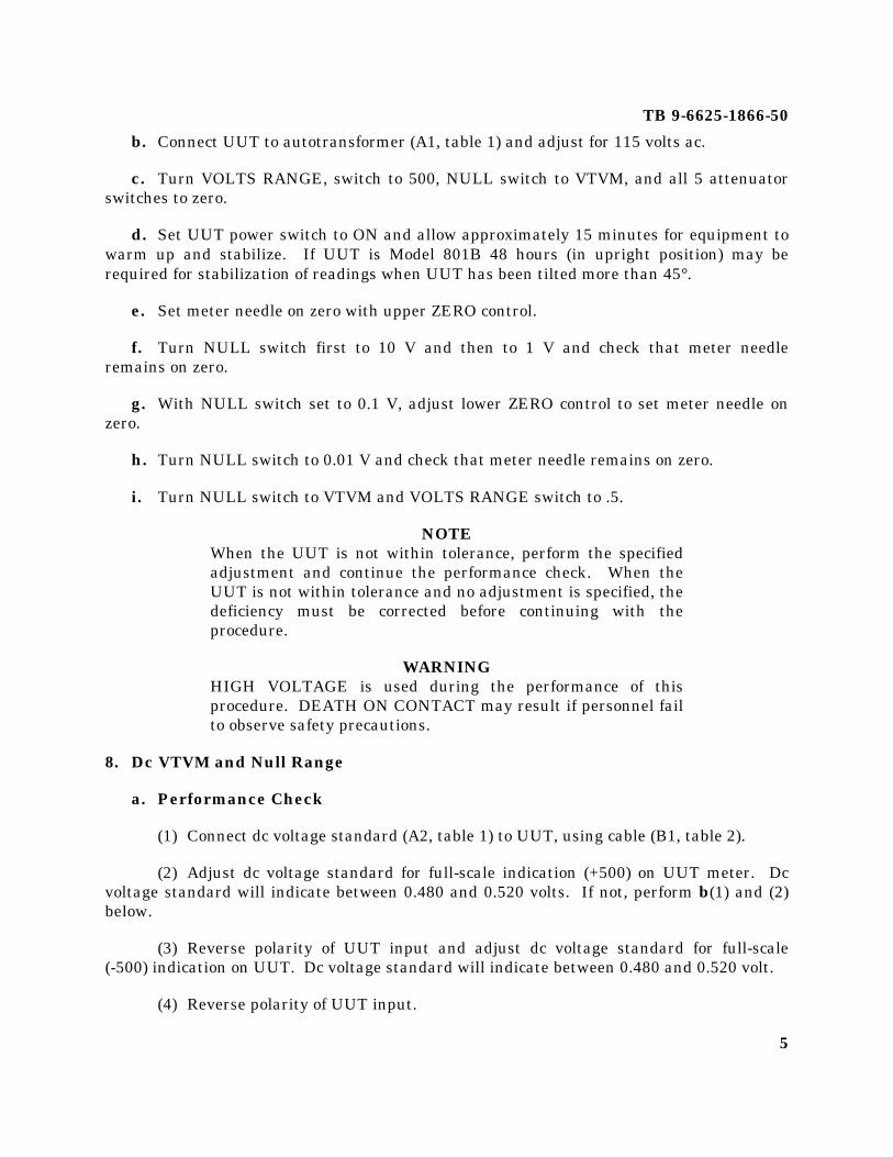
(2) Adjust P104 (fig. 1) until UUT indicates 500.
(3) Adjust dc voltage standard output to 10.00 mv.
(4) Adjust P103 (fig. 1) for full-scale indication on UUT.
TB 9-6625-1866-50
7
9. 500-Volt Range and Stability
a. Performance Check
(1) Turn UUT VOLTS RANGE switch to CAL and press and hold CAL PUSH (OPCAL to CAL) switch.
(2) Adjust ADJ CAL control for 0 (zero) indication on UUT meter. Observe thatADJ CAL control is within 90 degrees of center of its rotation. If not, perform b(1) and (2)below.
(3) Release CAL PUSH (OP-CAL, to OP) switch and turn VOLTS RANGE switch to500.
Figure 1. Differential voltmeter.

TB 9-6625-1866-50
8
(4) Repeat paragraph 7e through i. Connect dc voltage standard (A2, table 1) toUUT, using cable (B1, table 2).
(5) Turn UUT A, B, C, D, and E switches to 4, 9, 9, 9, and 10. Adjust dc voltagestandard for full-scale indication on UUT.
(6) Turn NULL switch to 10, 1, and .1 while adjusting dc voltage standard for 0(zero) indication on UUT meter. Dc voltage standard will indicate between 499.750 and500.250 volts. If not, perform b(3) through (9) below.
(7) While maintaining null on UUT with dc voltage standard, vary autotransformer(A1, table 1) from 105 to 125 Volts. Dc voltage standard output will remain between499.750 and 500.250 volts. If not, and no adjustment was performed in (6) above, performb(3) through (9) below.
(8) Adjust autotransformer output to 115 volts.
(9) Turn UUT NULL switch to VTVM.
(10) Adjust dc voltage standard for 0 (zero) indication on UUT meter.
b. Adjustments
(1) Center ADJ CAL knob.
(2) Press CAL PUSH switch while adjusting P6 (fig. 1) for zero indication on UUTmeter.
NOTESome models do not have CAL adjustment P6.
(3) Turn NULL switch to VTVM, and adjust dc voltage standard output to 500.000volts.
(4) Adjust ADJ CAL for null (0) indication on UUT NULL switch in 10, 1, .1 and .01V position.
(5) Turn NULL switch to VTVM.
(6) Adjust dc voltage standard for 0 (zero) volt.
(7) Turn VOLTS RANGE switch to CAL.
(8) Press and hold CAL PUSH (OP-CAL, to CAL) switch and adjust P2 (fig. 1) fornull on UUT.

TB 9-6625-1866-50
9
(9) Turn VOLTS RANGE switch to 500 and repeat a(5) and (6) above.
10. 50-Volt Range
a. Performance Check
(1) Turn, VOLTS RANGE switch to 50 and adjust dc voltage standard (A2, table 1)for full-scale indication on UUT meter.
(2) Turn NULL switch to 10, 1, and .1 while adjusting dc voltage standard for 0(zero) indication on UUT meter. Dc voltage standard will indicate between 49.975 and50.025 volts. If not, perform b below.
(3) Turn NULL switch to VTVM.
(4) Adjust dc voltage standard for 0 (zero) indication on UUT meter.
b. Adjustments
(1) Turn NULL switch to VTVM.
(2) Adjust dc voltage standard for 50.000 volts.
(3) Turn NULL switch to 10, 1, and .1 while adjusting P3 (fig. 1) for 0 (zero)indication on UUT meter.
11. 5-Volt Range
a. Performance Check
(1) Turn UUT VOLTS RANGE switch to 5.
(2) Adjust dc voltage standard (A2, table 1) for full-scale indication on UUT meter.
(3) Turn NULL switch to 10, 1, .1 and .01 while adjusting dc voltage standard for 0indication on UUT meter. Dc voltage standard will indicate between 4.9975 and 5.0025volts. If not, perform b below.
(4) Turn NULL switch to VTVM.
(5) Adjust dc voltage standard for 0 (zero) indication on UUT meter.
b. Adjustments
(1) Turn NULL switch to VTVM.
(2) Adjust dc voltage standard for 5.00000 volts.

TB 9-6625-1866-50
10
(3) Turn NULL switch to 10, 1, .1, and .01 while adjusting P4 (fig. 1) for 0 (zero)indication on UUT meter.
12. 0.5-Volt Range
a. Performance Check
(1) Turn VOLTS RANGE switch to .5.
(2) Adjust dc voltage standard (A2, table 1) for full-scale indication on UUT meter.
(3) Turn NULL switch to 10, 1, .1, and .01 while adjusting dc voltage standard for 0(zero) indication on UUT meter. Dc voltage standard will indicate between 0.49975 and0.50025 volt. If not, perform b below.
(4) Turn NULL switch to VTVM.
(5) Adjust dc voltage standard for 0 (zero) indication on UUT meter.
b. Adjustments
(1) Turn NULL switch to VTVM.
(2) Adjust dc voltage standard for 0.500000 volt.
(3) Turn NULL switch to 10, 1, .1 and .01 while adjusting P5 (fig. 1) for 0 (zero)indication on UUT meter.
13. Voltage Dividers
a. Performance Check
(1) Turn VOLTS RANGE switch to CAL and press and hold CAL PUSH (OP-CAL,to CAL) switch.
(2) Adjust CAL ADJ control for 0 (zero) indication on UUT meter.
(3) Release CAL PUSH (OP-CAL, to OP) switch.
(4) Turn VOLTS RANGE switch to 500 and A, B, C, D and E switches to 3, 9, 9, 9and 10.
(5) Adjust dc voltage standard (A2, table 1) to 400 volts.
(6) Turn NULL switch to 10, 1, .1, and .01 while adjusting dc voltage standard for 0(zero) indication on UUT meter for each NULL switch position. Dc voltage standard willindicate between 399.800 and 400.200 volts.
TB 9-6625-1866-50
11
(7) Turn NULL switch to VTVM.
(8) Adjust dc voltage standard for 0 (zero) indication on UUT meter.
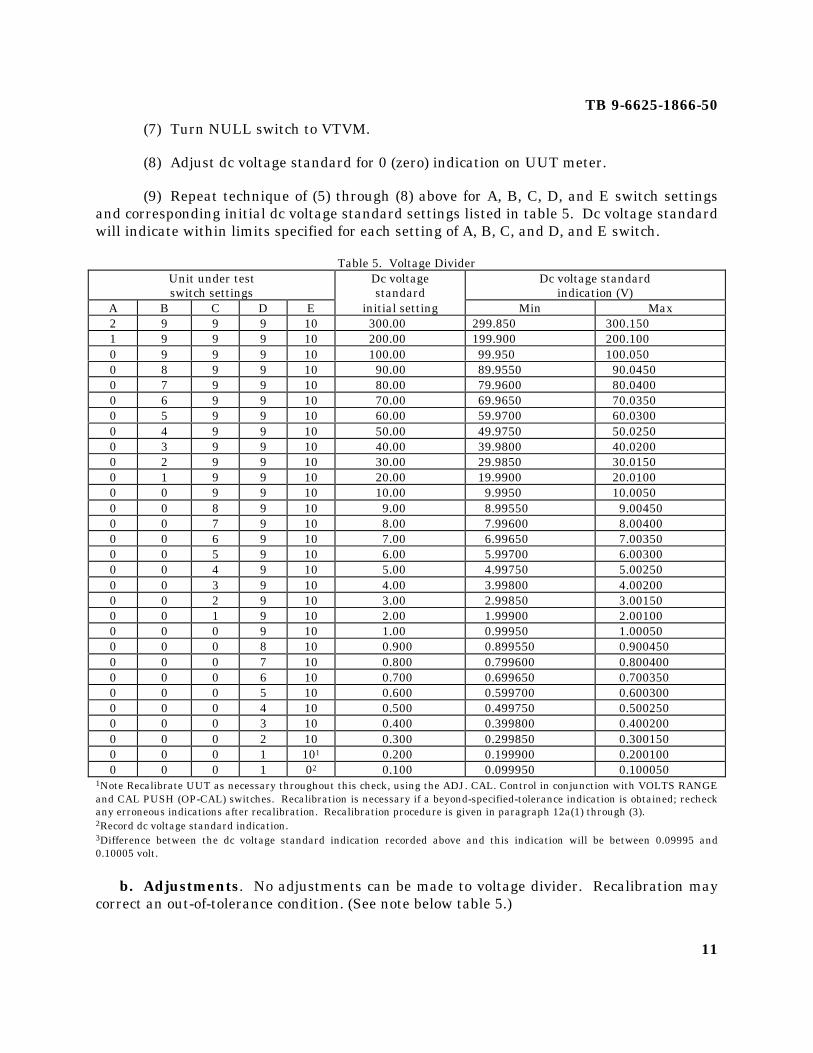
(9) Repeat technique of (5) through (8) above for A, B, C, D, and E switch settingsand corresponding initial dc voltage standard settings listed in table 5. Dc voltage standardwill indicate within limits specified for each setting of A, B, C, and D, and E switch.
Table 5. Voltage DividerUnit under test Dc voltage Dc voltage standardswitch settings standard indication (V)
A B C D E initial setting Min Max2 9 9 9 10 300.00 299.850 300.1501 9 9 9 10 200.00 199.900 200.1000 9 9 9 10 100.00 99.950 100.0500 8 9 9 10 90.00 89.9550 90.04500 7 9 9 10 80.00 79.9600 80.04000 6 9 9 10 70.00 69.9650 70.03500 5 9 9 10 60.00 59.9700 60.03000 4 9 9 10 50.00 49.9750 50.02500 3 9 9 10 40.00 39.9800 40.02000 2 9 9 10 30.00 29.9850 30.01500 1 9 9 10 20.00 19.9900 20.01000 0 9 9 10 10.00 9.9950 10.00500 0 8 9 10 9.00 8.99550 9.004500 0 7 9 10 8.00 7.99600 8.004000 0 6 9 10 7.00 6.99650 7.003500 0 5 9 10 6.00 5.99700 6.003000 0 4 9 10 5.00 4.99750 5.002500 0 3 9 10 4.00 3.99800 4.002000 0 2 9 10 3.00 2.99850 3.001500 0 1 9 10 2.00 1.99900 2.001000 0 0 9 10 1.00 0.99950 1.000500 0 0 8 10 0.900 0.899550 0.9004500 0 0 7 10 0.800 0.799600 0.8004000 0 0 6 10 0.700 0.699650 0.7003500 0 0 5 10 0.600 0.599700 0.6003000 0 0 4 10 0.500 0.499750 0.5002500 0 0 3 10 0.400 0.399800 0.4002000 0 0 2 10 0.300 0.299850 0.3001500 0 0 1 101 0.200 0.199900 0.2001000 0 0 1 02 0.100 0.099950 0.100050
1Note Recalibrate UUT as necessary throughout this check, using the ADJ. CAL. Control in conjunction with VOLTS RANGEand CAL PUSH (OP-CAL) switches. Recalibration is necessary if a beyond-specified-tolerance indication is obtained; recheckany erroneous indications after recalibration. Recalibration procedure is given in paragraph 12a(1) through (3).2Record dc voltage standard indication.3Difference between the dc voltage standard indication recorded above and this indication will be between 0.09995 and0.10005 volt.
b. Adjustments. No adjustments can be made to voltage divider. Recalibration maycorrect an out-of-tolerance condition. (See note below table 5.)
TB 9-6625-1866-50
12
14. Final Procedure
a. Deenergize and disconnect all equipment.
b. In accordance with TM 38-750, annotate and affix DA Label 80 (US Army CalibratedInstrument). When the TI receives limited or special calibration, annotate and affix DALabel 163 (US Army Limited or Special Calibration). When the TI cannot be adjustedwithin tolerance, annotate and affix DA Form 2417 (US Army Calibration System RejectedInstrument).
SECTION IIICALIBRATION OF DIFFERENTIAL VOLTMETERS AN/USM-98A AND AN/USM-
98B (J-F 801 B, J-F 801BR, AND J-F 801B/AG)
15. Equipment and Accessories Required. Table 6 lists minimum use specifications ofequipment required for calibration performance checks and adjustments. Table 7 listsrequired accessories. Tables 6 and 7 are provided to assist in the selection of requiredequipment and accessories. For specific item identification, refer to section IV.
Table 6. Minimum Specifications of Equipment RequiredItem
number Common name Minimum use specificationsA1 AUTOTRANSFORMER RANGE: 105 to 125 vac
ACCURACY: ±1%A2 DC VOLTAGE STANDARD RANGE: 0 to 515 v
ACCURACY: ±0.016%
Table 7. Accessories RequiredItem
number Common name DescriptionB1 CABLE 30-in., RG-58/U; double banana plug terminationsB2 LEAD 12-in., No. 18; single banana plug terminations (black)
16. Preliminary Procedure
NOTEPersonnel should familiarize themselves with the entirebulletin prior to performing calibration.
a. Remove protective cover from UUT as necessary to perform adjustments and replaceprotective cover to check parameter.
b. Connect UUT to autotransformer (A1, table 6).
c. Connect autotransformer to 115-volt ac source and adjust for 115 volts ac.
d. Mechanically zero UUT meter.

TB 9-6625-1866-50
13
c. Position UUT controls as listed in (1) through (4) below:
(1) RANGE switch to 5.
(2) NULL switch to .01.
(3) Polarity switch to + (positive).
(4) Voltage readout dials (A through E) to zero.
f. Set UUT power switch to on and allow at least 20 minutes for equipment to warm-up and stabilize.
g. Connect lead (B2, table 7) between UUT input terminals.
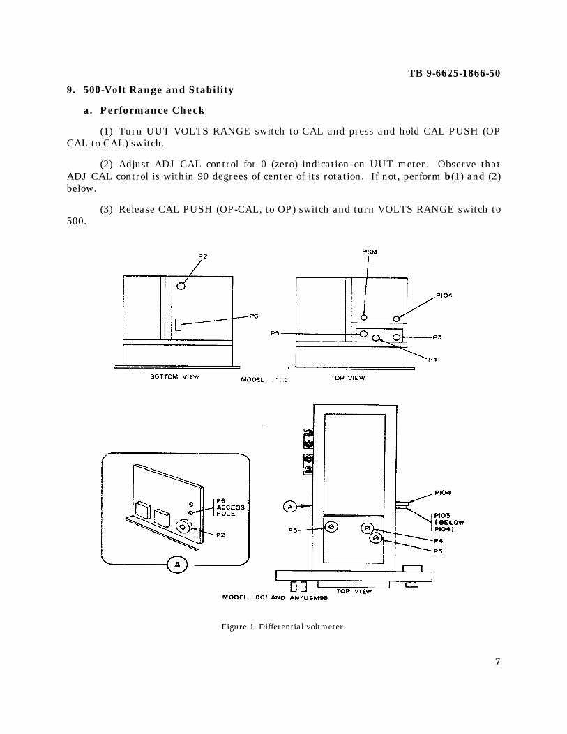
h. UUT meter will indicate zero. If not, adjust R227 (fig. 2) (rear of AN/USM-98B)until UUT meter indicates zero.
NOTEWhen the UUT is not within tolerance, perform the specifiedadjustment and continue the performance check. When theUUT is not within tolerance and no adjustment is specified, thedeficiency must be corrected before continuing with theprocedure.
WARNINGHIGH VOLTAGE is used during the performance of thisprocedure. DEATH ON CONTACT may result if personnel failto observe safety precautions.
17. Dc VTVM and Null Range
a. Performance Check
(1) Turn UUT NULL switch to VTVM and RANGE switch to .5.
(2) Connect dc voltage standard (A2, table 6) output to UUT input terminal, usingcable (B1, table 7).
(3) Adjust dc voltage standard output until UUT meter indicates 500. Dc voltagestandard will indicate between 0.485 and 0.515 volt. If not, perform b below.
(4) Turn UUT RANGE switch to settings listed in table 8 and repeat technique of(3) above. Voltage standard will indicate within limits specified.

TB 9-6625-1866-50
14
MI © 6625-1866-50-2
Figure 2. Differential voltmeter.

TB 9-6625-1866-50
15
(5) Turn UUT polarity switch to - (negative).
(6) Repeat (1) through (3) above for negative indications on UUT meter.
(7) Adjust dc voltage standard for 0 (zero) indication on UUT meter and turn UUTNULL switch to .01.
Table 8. Dc VTVMUnit under test Dc voltage standard indication (V)
Range switchposition
Meter indication Min Max
5 100 0.85 1.155 200 1.85 2.155 300 2.85 3.155 400 3.85 4.155 500 4.85 5.15
50 500 48.5 51.5500 500 485 515
(8) Adjust dc voltage standard output until UUT meter indicates a negative 10 mV(100 on lower scale). Dc voltage standard will indicate between 9.7 and 10.3 mV.
(9) Repeat technique of (7) and (8) above for settings and indications listed in table9. Dc voltage standard indications will be within limits specified.
Table 9. Null RangeUnit Under Test Dc voltage standard
NULL Meter indication indicationswitch position (lower scale) Min Max
.1 100 97 mV 103 mV1 100 0.97 V 1.03 V
10 100 9.7 V 10.3 V
(10) Turn UUT polarity switch to + (positive).
(11) Repeat technique of (7) through (9) above for positive indications on UUT meter.
(12) Turn UUT NULL switch to VTVM.
b. Adjustments
(1) Adjust dc voltage standard output to .500 volt.
(2) Adjust R219 (fig. 2) (rear of AN/USM -98B) until UUT meter indicates 500.
TB 9-6625-1866-50
16
18. 500-Volt Range and Stability
a. Performance Check
(1) Position UUT A, B, C, D, and E dials to 4.9, 9, 9 and 10 and RANGE switch to500.
(2) Turn OPERATE-CALIBRATE switch to CALIBRATE and hold. AdjustCALIBRATE control for null on meter. Release OPERATE-CALIBRATE switch. TheCALIBRATE control will be within 90 degrees of midrange. If not, perform b below.
(3) Adjust dc voltage standard (A2, table 6) to 500 volts.
(4) Turn NULL switch to 10, 1, and .1 while adjusting dc voltage standard for 0(zero) indication on UUT meter. Dc voltage standard will indicate between 499.75 and500.25 volts. If not, and no adjustment was made in (2) above, perform b below.
(5) While maintaining null on UUT with dc voltage standard, vary autotransformer(A1, table 6) from 105 to 125 volts (wait 1 minute at 105 and 125 volts). Dc voltagestandard output will remain between 499.75 and 500.25 volts. If not, and no adjustmentwas performed in (2) or (4) above, perform b below.
(6) Adjust autotransformer output to 115 volts.
(7) Turn UUT NULL switch to VTVM.
(8) Adjust dc voltage standard for 0 (zero) indication on UUT meter.
b. Adjustments
(1) Turn NULL switch to VTVM and CALIBRATE control to midrange. Adjust dcvoltage standard for 500.000 volts.
(2) Turn NULL switch to 10, 1, and .1 while adjusting R121 (fig. 2) (rear ofAN/USM-98B). Continue adjustment until NULL is obtained in .1 NULL switch position.
(3) Turn OPERATE-CALIBRATE switch to CALIBRATE and hold. Adjust R318(fig. 2 or 3) for NULL on UUT meter.
(4) Release OPERATE-CALIBRATE switch.
19. 50-Volt Range
a. Performance Check
(1) Turn VOLTS RANGE switch to 50.
TB 9-6625-1866-50
17
(2) Adjust dc voltage standard (A2, table 6) for full-scale indication on UUT meter.
(3) Turn NULL switch to 10, 1, .1, and .01 while adjusting dc voltage standard for 0(zero) indication on UUT meter. Dc voltage standard will indicate between 49.975 and50.025 volts. If not, perform b below.
(4) Turn NULL switch to VTVM.
(5) Adjust dc voltage standard for 0 (zero) indication on UUT meter.
b. Adjustments
(1) Turn NULL switch to VTVM.
(2) Adjust dc voltage standard for 50.000 volts.
(3) Turn NULL switch to 10, 1, .1 and .01 while adjusting R323 (fig. 2 or 3) for0 (zero) indication on UUT meter.
20. 5-Volt Range
a. Performance Check
(1) Turn UUT VOLTS RANGE switch to 5.
(2) Adjust dc voltage standard (A2, table 6) for full-scale indication on UUT meter
(3) Turn NULL switch to 10, 1, .1 and .01 while adjusting dc voltage standard for0 (zero) indication on UUT meter. Dc voltage standard will indicate between 4.9975 and5.0025 volts. If not, perform b below.
(2) Turn NULL switch to VTVM.
(5) Adjust dc voltage standard for 0 (zero) indication on UUT meter.
b. Adjustments
(1) Turn NULL switch to VTVM.
(2) Adjust dc voltage standard for 5.00000 Volts.
(3) Turn NULL switch to 10, 1, .1, and .01 while adjusting R326 (fig. 2 or 3) for0 (zero) indication on UUT meter.
TB 9-6625-1866-50
18
MC © 6625-1866-50-3
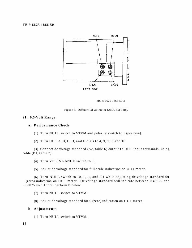
Figure 3. Differential voltmeter (AN/USM-98B).
21. 0.5-Volt Range
a. Performance Check
(1) Turn NULL switch to VTVM and polarity switch to + (positive).
(2) Turn UUT A, B, C, D, and E dials to 4, 9, 9, 9, and 10.
(3) Connect dc voltage standard (A2, table 6) output to UUT input terminals, usingcable (B1, table 7).
(4) Turn VOLTS RANGE switch to .5.
(5) Adjust dc voltage standard for full-scale indication on UUT meter.
(6) Turn NULL switch to 10, 1, .1, and .01 while adjusting dc voltage standard for0 (zero) indication on UUT meter. Dc voltage standard will indicate between 0.49975 and0.50025 volt. If not, perform b below.
(7) Turn NULL switch to VTVM.
(8) Adjust dc voltage standard for 0 (zero) indication on UUT meter.
b. Adjustments
(1) Turn NULL switch to VTVM.
TB 9-6625-1866-50
19
(2) Adjust dc voltage standard for 0.500000 volt.
(3) Turn NULL switch to 10, 1, .1, and .01 while adjusting R329 (fig. 2 or 3) for0 (zero) indication on UUT meter.
22. Voltage Dividers
a. Performance Check
(1) Turn UUT RANGE selector switch to 500 and A, B, C, D, and E dials to 3, 9, 9, 9and 10.
(2) Adjust dc voltage standard (A2, table 1) to 400 volts.
(3) Turn NULL switch to 10, 1, and .1 positions and at each position adjust dcvoltage standard for null indication on UUT meter. Dc voltage standard will indicatebetween 399.80 and 400.20 volts.
(4) Turn NULL switch to VTVM.
(5) Adjust dc voltage standard for 0 (zero) indication on UUT meter.
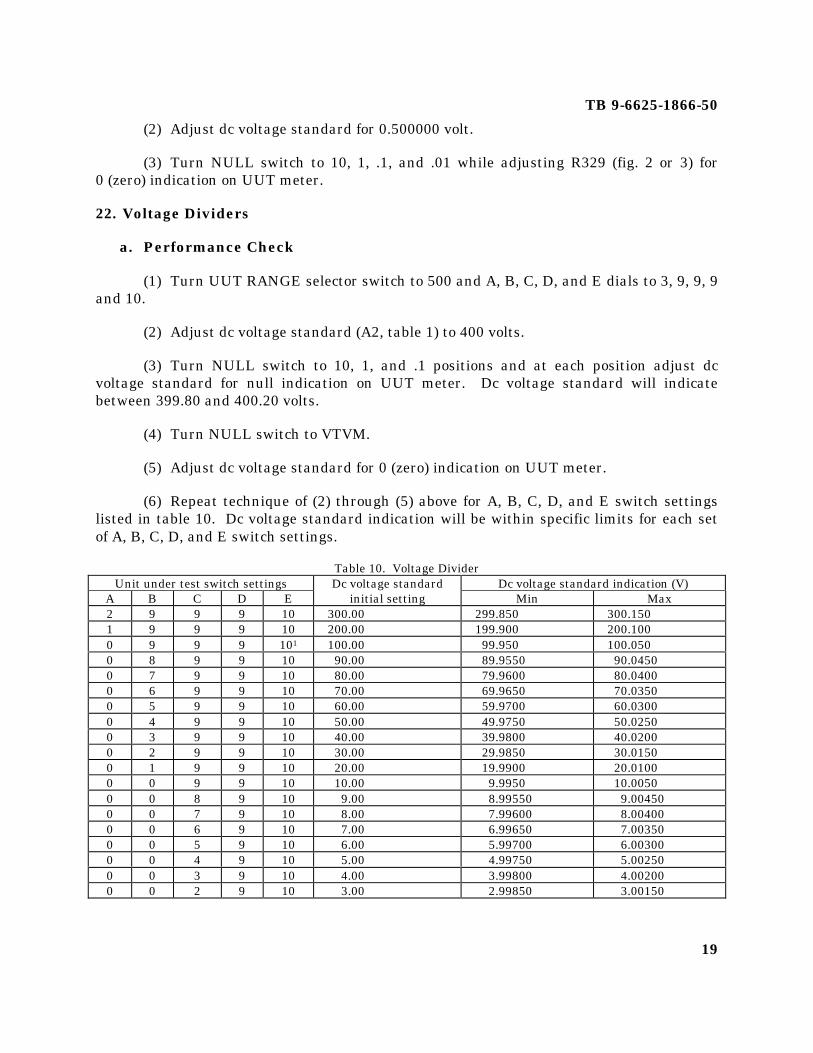
(6) Repeat technique of (2) through (5) above for A, B, C, D, and E switch settingslisted in table 10. Dc voltage standard indication will be within specific limits for each setof A, B, C, D, and E switch settings.
Table 10. Voltage DividerUnit under test switch settings Dc voltage standard Dc voltage standard indication (V)
A B C D E initial setting Min Max2 9 9 9 10 300.00 299.850 300.1501 9 9 9 10 200.00 199.900 200.1000 9 9 9 101 100.00 99.950 100.0500 8 9 9 10 90.00 89.9550 90.04500 7 9 9 10 80.00 79.9600 80.04000 6 9 9 10 70.00 69.9650 70.03500 5 9 9 10 60.00 59.9700 60.03000 4 9 9 10 50.00 49.9750 50.02500 3 9 9 10 40.00 39.9800 40.02000 2 9 9 10 30.00 29.9850 30.01500 1 9 9 10 20.00 19.9900 20.01000 0 9 9 10 10.00 9.9950 10.00500 0 8 9 10 9.00 8.99550 9.004500 0 7 9 10 8.00 7.99600 8.004000 0 6 9 10 7.00 6.99650 7.003500 0 5 9 10 6.00 5.99700 6.003000 0 4 9 10 5.00 4.99750 5.002500 0 3 9 10 4.00 3.99800 4.002000 0 2 9 10 3.00 2.99850 3.00150
TB 9-6625-1866-50
20
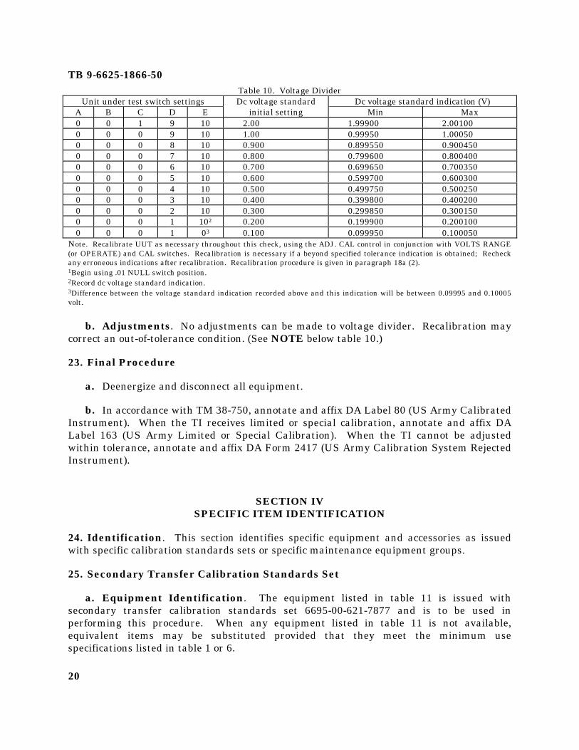
Table 10. Voltage DividerUnit under test switch settings Dc voltage standard Dc voltage standard indication (V)
A B C D E initial setting Min Max0 0 1 9 10 2.00 1.99900 2.001000 0 0 9 10 1.00 0.99950 1.000500 0 0 8 10 0.900 0.899550 0.9004500 0 0 7 10 0.800 0.799600 0.8004000 0 0 6 10 0.700 0.699650 0.7003500 0 0 5 10 0.600 0.599700 0.6003000 0 0 4 10 0.500 0.499750 0.5002500 0 0 3 10 0.400 0.399800 0.4002000 0 0 2 10 0.300 0.299850 0.3001500 0 0 1 102 0.200 0.199900 0.2001000 0 0 1 03 0.100 0.099950 0.100050
Note. Recalibrate UUT as necessary throughout this check, using the ADJ. CAL control in conjunction with VOLTS RANGE(or OPERATE) and CAL switches. Recalibration is necessary if a beyond specified tolerance indication is obtained; Recheckany erroneous indications after recalibration. Recalibration procedure is given in paragraph 18a (2).1Begin using .01 NULL switch position.2Record dc voltage standard indication.3Difference between the voltage standard indication recorded above and this indication will be between 0.09995 and 0.10005volt.
b. Adjustments. No adjustments can be made to voltage divider. Recalibration maycorrect an out-of-tolerance condition. (See NOTE below table 10.)
23. Final Procedure
a. Deenergize and disconnect all equipment.
b. In accordance with TM 38-750, annotate and affix DA Label 80 (US Army CalibratedInstrument). When the TI receives limited or special calibration, annotate and affix DALabel 163 (US Army Limited or Special Calibration). When the TI cannot be adjustedwithin tolerance, annotate and affix DA Form 2417 (US Army Calibration System RejectedInstrument).
SECTION IVSPECIFIC ITEM IDENTIFICATION
24. Identification. This section identifies specific equipment and accessories as issuedwith specific calibration standards sets or specific maintenance equipment groups.
25. Secondary Transfer Calibration Standards Set
a. Equipment Identification. The equipment listed in table 11 is issued withsecondary transfer calibration standards set 6695-00-621-7877 and is to be used inperforming this procedure. When any equipment listed in table 11 is not available,equivalent items may be substituted provided that they meet the minimum usespecifications listed in table 1 or 6.

TB 9-6625-1866-50
21
Table 11. Equipment IdentificationItem
number Nomenclature Identifying numberManufacturer and model
numberA1 TRANSFORMER, VARIABLE
POWER7910809 General Radio, Model
W10MT3AS3A2 VOLTAGE STANDARD, DC 7911393 Cohu, Model 351 or John
Fluke, Model 332A
b. Accessory Identification. The accessories listed in table 12 are issued withsecondary transfer calibration standards set 6695-00-621-7877 and are to be used inperforming this procedure. These accessories may be substituted unless specificallyprohibited.
Table 12. Accessory IdentificationItem
Number Nomenclature Identifying number DescriptionB1 CABLE ASSEMBLY,
RADIO FREQUENCY7907470 30-in., RF-58/U; double banana
plug terminationsB2 LEAD, ELECTRICAL 7907496 12-in., No. 18; single banana plug
terminations (black)

TB 9-6625-1866-50
PIN NO: 010886-000
By Order of the Secretary of the Army:
W. C. WESTMORELANDGeneral, United States Army
Chief Of Staff
Official:
KENNETH G. WICKHAMMajor General, United States Army
The Adjutant GeneralDistribution:
Active Army:TAG (1) USAERDAA (22) Cornhusker Army Ammo Plant (1)TIG (2) USAARMC (11) Lake City Army Ammo Plant (1)ARADCOM (2) USAGETA (2) Sunflower Army Ammo Plant (2)ARADCOM Rgn (2) USA Mat & Mech Rsch Cen (2) Longhorn Army Ammo Plant (1)USARHAW (4) USAMCI&SA (3) Milan Army Ammo Plant (1)USARPAC (2) USANDL (2) Newport Army Ammo Plant (1)2d LOGCOMD (40) NLABS (2) Radford Army Ammo Plant (1)USATECOM (1) USARSO (4) Louisiana Army Ammo Plant (1)USAMC - Europe (2) USARADBD (2) Rocky Mountain Arsenal (2)USA Arberdeen R&D Cen (4) USAVLABS (2) Picatinny Arsenal (5)USAMUCOM (2) USACRREL (2) Edgewood Arsenal (4)USAECOM (10) Harry Diamond Lab (2) Frankford Arsenal (5)USACDCEC (10) APG (2) Pine Bluff Arsenal (2)USA SAFSCOM (3) DTC (2) Rock Island Arsenal (2)USAAPSA (4) USAEPG (3) Albrook AFB (3)USAMICOM (59) JPG (2) WSMR (6)USAWECOM (34) YPG (2) USATTC (2)USAMECOM (2) ANAD (20) Elmendorf AFB (3)USAAVSCOM (19) USARJ (7) Flat-Top Fld Ofc (3)USATACOM (2) USA Camp Carrol Dep (14) Davis-Monthan AFB (5)USASA Mat Spt Comd (2) LEAD (37) USAMC Taiwan Mat Agcy (1)USAMC (2) UMAD (2) AMC Nuc Actv Fld Ofc (3)USATOPOCOM (2) SHAD (4) SAMSO (SMSDI) (6)Armies (3) except Eighth SIAD (2) Newark AF Sta (1)US Army (1) LBAD (20) Norfolk Naval Air Sta (1)138th Ord Co (2) PUAD (20) Naval Air Tech Svc Fac (1)Ft Detrick (2) SEAD (2) Pirmasens Army Dep (75)Ft Hood (5) SAAD (18) USN Air Dev Cen (2)Korea Spt Cmd (1) SVAD (6) Comdt of Marine Corps (8)USAOC&S (21) RRAD (4) NYU (2)USAMMCS (1) TOAD (19) NAVPRO MEC Lib (2)USAATC (2) TEAD (42) USARAL (2)ARADMAC (4) Iowa Army Ammo Plant (1)USAMERDC (2) Indiana Army Ammo Plant (6)NG: NoneUSAR: NoneFor explanation of abbreviations used, see AR 310-50
US G.P.O. 1980 640-217/90