Fluids Pascal's Principle Measuring Pressure...
31
Fluids Fluid Dynamics Lana Sheridan De Anza College April 15, 2020
Transcript of Fluids Pascal's Principle Measuring Pressure...

FluidsFluid Dynamics
Lana Sheridan
De Anza College
April 15, 2020
Last time
• Pascal’s principle
• measurements of pressure
• introduced fluid dynamics
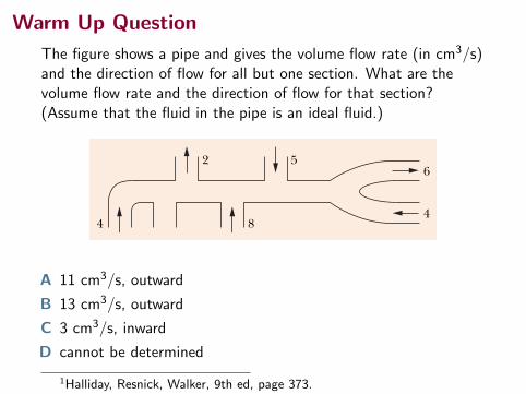
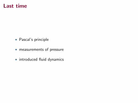
Warm Up Question
The figure shows a pipe and gives the volume flow rate (in cm3/s)and the direction of flow for all but one section. What are thevolume flow rate and the direction of flow for that section?(Assume that the fluid in the pipe is an ideal fluid.)
37314-9 TH E EQUATION OF CONTI N U ITYPART 2
We can rewrite Eq. 14-23 as
RV ! Av ! a constant (volume flow rate, equation of continuity), (14-24)
in which RV is the volume flow rate of the fluid (volume past a given point perunit time). Its SI unit is the cubic meter per second (m3/s). If the density r of thefluid is uniform, we can multiply Eq. 14-24 by that density to get the mass flowrate Rm (mass per unit time):
Rm ! rRV ! rAv ! a constant (mass flow rate). (14-25)
The SI unit of mass flow rate is the kilogram per second (kg/s). Equation 14-25says that the mass that flows into the tube segment of Fig. 14-15 each second mustbe equal to the mass that flows out of that segment each second.
CHECKPOINT 3
The figure shows a pipe and gives the volume flow rate (in cm3/s) and the di-rection of flow for all but one section. What are the volume flow rate and thedirection of flow for that section?
4 8
2 56
4
Sample Problem
A water stream narrows as it falls
Figure 14-18 shows how the stream of water emerging froma faucet “necks down” as it falls. This change in the horizontalcross-sectional area is characteristic of any laminar (non-turbulant) falling stream because the gravitational forceincreases the speed of the stream. Here the indicatedcross-sectional areas are A0 ! 1.2 cm2 and A ! 0.35 cm2.The two levels are separated by a vertical distance h ! 45 mm.What is the volume flow rate from the tap?
KEY I DEA
Fig. 14-18 As water falls from a tap, its speedincreases. Because the volume flow rate must bethe same at all horizontal cross sections of thestream, the stream must “neck down” (narrow).
h
A0
A
The volume flow persecond here mustmatch ...
... the volume flowper second here.
The volume flow rate through the higher cross section mustbe the same as that through the lower cross section.
Calculations: From Eq. 14-24, we have
A0v0 ! Av, (14-26)
where v0 and v are the water speeds at the levels correspond-ing to A0 and A. From Eq. 2-16 we can also write, because thewater is falling freely with acceleration g,
v2 ! v20 " 2gh. (14-27)
Eliminating v between Eqs. 14-26 and 14-27 and solving forv0, we obtain
! 0.286 m/s ! 28.6 cm/s.
From Eq. 14-24, the volume flow rate RV is thenRV ! A0v0 ! (1.2 cm2)(28.6 cm/s)
! 34 cm3/s. (Answer)
! A (2)(9.8 m/s2)(0.045 m)(0.35 cm2)2
(1.2 cm2)2 # (0.35 cm2)2
v0 ! A 2ghA2
A20 # A2
Additional examples, video, and practice available at WileyPLUS
halliday_c14_359-385hr.qxd 26-10-2009 21:40 Page 373
A 11 cm3/s, outward
B 13 cm3/s, outward
C 3 cm3/s, inward
D cannot be determined
1Halliday, Resnick, Walker, 9th ed, page 373.
Overview
• fluid dynamics
• the continuity equation
• Bernoulli’s equation
• Torricelli’s law (?)
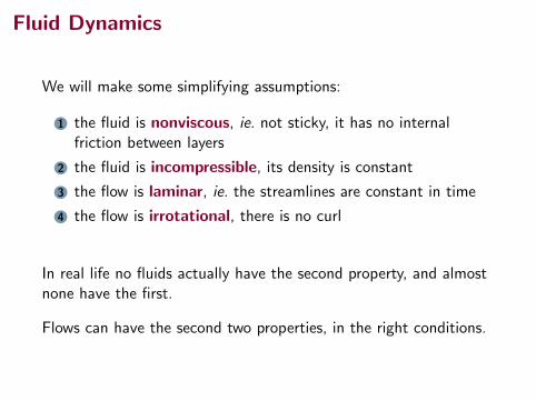
Fluid Dynamics
We will make some simplifying assumptions:
1 the fluid is nonviscous, ie. not sticky, it has no internalfriction between layers
2 the fluid is incompressible, its density is constant
3 the flow is laminar, ie. the streamlines are constant in time
4 the flow is irrotational, there is no curl
In real life no fluids actually have the second property, and almostnone have the first.
Flows can have the second two properties, in the right conditions.
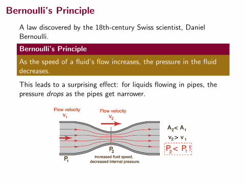
Bernoulli’s Principle
A law discovered by the 18th-century Swiss scientist, DanielBernoulli.
Bernoulli’s Principle
As the speed of a fluid’s flow increases, the pressure in the fluiddecreases.
This leads to a surprising effect: for liquids flowing in pipes, thepressure drops as the pipes get narrower.
Bernoulli’s Principle
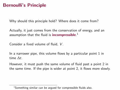
Why should this principle hold? Where does it come from?
Actually, it just comes from the conservation of energy, and anassumption that the fluid is incompressible.1
Consider a fixed volume of fluid, V .
In a narrower pipe, this volume flows by a particular point 1 intime ∆t.
However, it must push the same volume of fluid past a point 2 inthe same time. If the pipe is wider at point 2, it flows more slowly.
1Something similar can be argued for compressible fluids also.
Bernoulli’s Principle
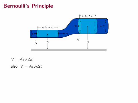
V = A1v1∆t
also, V = A2v2∆t
This means
A1v1 = A2v2
The “Continuity equation”.

Bernoulli’s Principle
V = A1v1∆t
also, V = A2v2∆t
This means
A1v1 = A2v2
The “Continuity equation”.
Bernoulli’s Equation
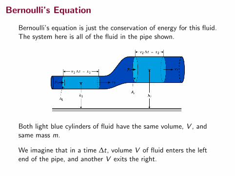
Bernoulli’s equation is just the conservation of energy for this fluid.The system here is all of the fluid in the pipe shown.
Both light blue cylinders of fluid have the same volume, V , andsame mass m.
We imagine that in a time ∆t, volume V of fluid enters the leftend of the pipe, and another V exits the right.
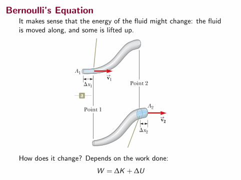
Bernoulli’s EquationIt makes sense that the energy of the fluid might change: the fluidis moved along, and some is lifted up.
428 Chapter 14 Fluid Mechanics
The path taken by a fluid particle under steady flow is called a streamline. The velocity of the particle is always tangent to the streamline as shown in Figure 14.15. A set of streamlines like the ones shown in Figure 14.15 form a tube of flow. Fluid particles cannot flow into or out of the sides of this tube; if they could, the stream-lines would cross one another. Consider ideal fluid flow through a pipe of nonuniform size as illustrated in Fig-ure 14.16. Let’s focus our attention on a segment of fluid in the pipe. Figure 14.16a shows the segment at time t 5 0 consisting of the gray portion between point 1 and point 2 and the short blue portion to the left of point 1. At this time, the fluid in the short blue portion is flowing through a cross section of area A1 at speed v1. During the time interval Dt, the small length Dx1 of fluid in the blue portion moves past point 1. During the same time interval, fluid at the right end of the segment moves past point 2 in the pipe. Figure 14.16b shows the situation at the end of the time interval Dt. The blue portion at the right end represents the fluid that has moved past point 2 through an area A2 at a speed v2. The mass of fluid contained in the blue portion in Figure 14.16a is given by m1 5 rA1 Dx1 5 rA1v1 Dt, where r is the (unchanging) density of the ideal fluid. Similarly, the fluid in the blue portion in Figure 14.16b has a mass m2 5 rA2 Dx2 5 rA2v2 Dt. Because the fluid is incompressible and the flow is steady, however, the mass of fluid that passes point 1 in a time interval Dt must equal the mass that passes point 2 in the same time interval. That is, m1 5 m2 or rA1v1 Dt 5 rA2v2 Dt, which means that
A1v1 5 A2v2 5 constant (14.7)
This expression is called the equation of continuity for fluids. It states that the product of the area and the fluid speed at all points along a pipe is constant for an incompressible fluid. Equation 14.7 shows that the speed is high where the tube is constricted (small A) and low where the tube is wide (large A). The product Av, which has the dimensions of volume per unit time, is called either the volume flux or the flow rate. The condition Av 5 constant is equivalent to the statement that the vol-ume of fluid that enters one end of a tube in a given time interval equals the volume leaving the other end of the tube in the same time interval if no leaks are present. You demonstrate the equation of continuity each time you water your garden with your thumb over the end of a garden hose as in Figure 14.17. By partially block-
Equation of Continuity Xfor Fluids
Figure 14.17 The speed of water spraying from the end of a garden hose increases as the size of the opening is decreased with the thumb.©
Cen
gage
Lea
rnin
g/Ge
orge
Sem
ple
vS
At each point along its path, the particle’s velocity is tangent to the streamline.
Figure 14.15 A particle in laminar flow follows a streamline.
v2
v1
At t ! 0, fluid in the blueportion is moving pastpoint 1 at velocity v1.
After a time interval "t,the fluid in the blue portion is moving past point 2 at velocity v2.
"x1
"x2
Point 2
Point 1
A1
A2
a
S
S
S
S
b
Figure 14.16 A fluid moving with steady flow through a pipe of varying cross-sectional area. (a) At t 5 0, the small blue-colored portion of the fluid at the left is moving through area A1. (b) After a time interval Dt, the blue-colored portion shown here is that fluid that has moved through area A2.
How does it change? Depends on the work done:
W = ∆K + ∆U

Bernoulli’s Equation
430 Chapter 14 Fluid Mechanics
14.6 Bernoulli’s EquationYou have probably experienced driving on a highway and having a large truck pass you at high speed. In this situation, you may have had the frightening feeling that your car was being pulled in toward the truck as it passed. We will investigate the origin of this effect in this section. As a fluid moves through a region where its speed or elevation above the Earth’s surface changes, the pressure in the fluid varies with these changes. The relationship between fluid speed, pressure, and elevation was first derived in 1738 by Swiss physicist Daniel Bernoulli. Consider the flow of a segment of an ideal fluid through a nonuniform pipe in a time interval Dt as illustrated in Figure 14.18. This figure is very similar to Figure 14.16, which we used to develop the continuity equation. We have added two features: the forces on the outer ends of the blue portions of fluid and the heights of these portions above the reference position y 5 0. The force exerted on the segment by the fluid to the left of the blue portion in Figure 14.18a has a magnitude P1A1. The work done by this force on the segment in a time interval Dt is W1 5 F1 Dx1 5 P1A1 Dx1 5 P1V, where V is the volume of the blue portion of fluid passing point 1 in Figure 14.18a. In a similar manner, the work done on the segment by the fluid to the right of the segment in the same time interval Dt is W2 5 2P2A2 Dx2 5 2P2V, where V is the volume of the blue portion of fluid passing point 2 in Figure 14.18b. (The volumes of the blue portions of fluid in Figures 14.18a and 14.18b are equal because the fluid is incompressible.) This work is negative because the force on the segment of fluid is to the left and the displace-ment of the point of application of the force is to the right. Therefore, the net work done on the segment by these forces in the time interval Dt is
W 5 (P1 2 P2)V
Finalize The time interval for the element of water to fall to the ground is unchanged if the projection speed is changed because the projection is horizontal. Increasing the projection speed results in the water hitting the ground farther from the end of the hose, but requires the same time interval to strike the ground.
y1
y2
The pressure atpoint 1 is P1.
P1A1 i
The pressure atpoint 2 is P2. v2
v1!x1
!x2
Point 2
Point 1a
S
S
"P2A2 i
ˆ
ˆ
b
Figure 14.18 A fluid in laminar flow through a pipe. (a) A segment of the fluid at time t 5 0. A small portion of the blue-colored fluid is at height y1 above a reference position. (b) After a time interval Dt, the entire segment has moved to the right. The blue-colored por-tion of the fluid is that which has passed point 2 and is at height y2.
▸ 14.7 c o n t i n u e d
Daniel BernoulliSwiss physicist (1700–1782)Bernoulli made important discoveries in fluid dynamics. Bernoulli’s most famous work, Hydrodynamica, was published in 1738; it is both a theoreti-cal and a practical study of equilibrium, pressure, and speed in fluids. He showed that as the speed of a fluid increases, its pressure decreases. Referred to as “Bernoulli’s principle,” Bernoulli’s work is used to produce a partial vacuum in chemical laboratories by connecting a vessel to a tube through which water is running rapidly.
. iS
tock
phot
o.co
m/Z
U_09
The work done is the sum of thework done on each end of thefluid by more fluid that is oneither side of it:
W = F1∆x1 − F2∆x2
= P1A1∆x1 − P2A2∆x2
(The “environment fluid” just tothe right of the system fluid doesnegative work on the system as itmust be pushed aside by thesystem fluid.)
1Diagram from Serway & Jewett.

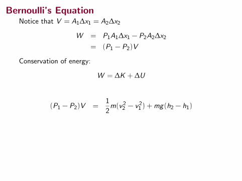
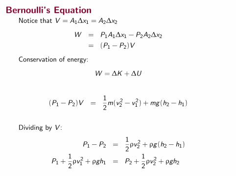
Bernoulli’s EquationNotice that V = A1∆x1 = A2∆x2
W = P1A1∆x1 − P2A2∆x2
= (P1 − P2)V
Conservation of energy:
W = ∆K + ∆U
(P1 − P2)V =1
2m(v22 − v21 ) +mg(h2 − h1)
Dividing by V :
P1 − P2 =1
2ρv22 + ρg(h2 − h1)
P1 +1
2ρv21 + ρgh1 = P2 +
1
2ρv22 + ρgh2
Bernoulli’s EquationNotice that V = A1∆x1 = A2∆x2
W = P1A1∆x1 − P2A2∆x2
= (P1 − P2)V
Conservation of energy:
W = ∆K + ∆U
(P1 − P2)V =1
2m(v22 − v21 ) +mg(h2 − h1)
Dividing by V :
P1 − P2 =1
2ρv22 + ρg(h2 − h1)
P1 +1
2ρv21 + ρgh1 = P2 +
1
2ρv22 + ρgh2
Bernoulli’s EquationNotice that V = A1∆x1 = A2∆x2
W = P1A1∆x1 − P2A2∆x2
= (P1 − P2)V
Conservation of energy:
W = ∆K + ∆U
(P1 − P2)V =1
2m(v22 − v21 ) +mg(h2 − h1)
Dividing by V :
P1 − P2 =1
2ρv22 + ρg(h2 − h1)
P1 +1
2ρv21 + ρgh1 = P2 +
1
2ρv22 + ρgh2
Bernoulli’s Equation
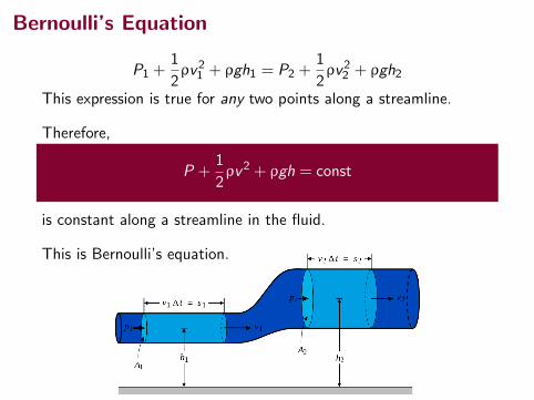
P1 +1
2ρv21 + ρgh1 = P2 +
1
2ρv22 + ρgh2
This expression is true for any two points along a streamline.
Therefore,
P +1
2ρv2 + ρgh = const
is constant along a streamline in the fluid.
This is Bernoulli’s equation.
Bernoulli’s Equation
P +1
2ρv2 + ρgh = const
Even though we derived this expression for the case of anincompressible fluid, this is also true (to first order) forcompressible fluids, like air and other gases.
The constraint is that the densities should not vary too much fromthe ambient density ρ.

Bernoulli’s Principle from Bernoulli’s Equation
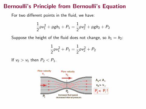
For two different points in the fluid, we have:
1
2ρv21 + ρgh1 + P1 =
1
2ρv22 + ρgh2 + P2
Suppose the height of the fluid does not change, so h1 = h2:
1
2ρv21 + P1 =
1
2ρv22 + P2
If v2 > v1 then P2 < P1.

Bernoulli’s Principle from Bernoulli’s Equation
For two different points in the fluid, we have:
1
2ρv21 + ρgh1 + P1 =
1
2ρv22 + ρgh2 + P2
Suppose the height of the fluid does not change, so h1 = h2:
1
2ρv21 + P1 =
1
2ρv22 + P2
If v2 > v1 then P2 < P1.
Bernoulli’s Principle from Bernoulli’s Equation
For two different points in the fluid, we have:
1
2ρv21 + ρgh1 + P1 =
1
2ρv22 + ρgh2 + P2
Suppose the height of the fluid does not change, so h1 = h2:
1
2ρv21 + P1 =
1
2ρv22 + P2
If v2 > v1 then P2 < P1.

Bernoulli’s Principle
However, from the continuity equation A1v1 = A2v2 we can seethat if A2 is smaller than A1, v2 is bigger than v1.
So the pressure really does fall as the pipe contracts!
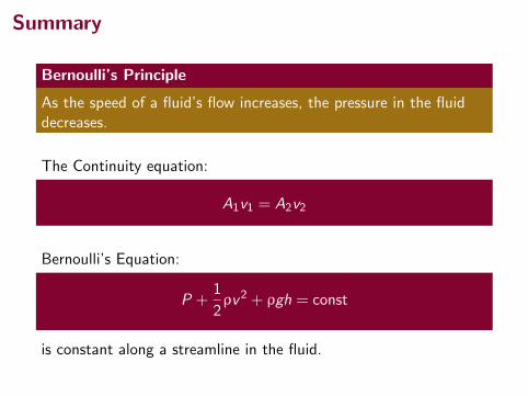
Summary
Bernoulli’s Principle
As the speed of a fluid’s flow increases, the pressure in the fluiddecreases.
The Continuity equation:
A1v1 = A2v2
Bernoulli’s Equation:
P +1
2ρv2 + ρgh = const
is constant along a streamline in the fluid.

QuestionWater flows smoothly through the pipe shown in the figure,descending in the process. Rank the four numbered sections of pipeaccording to the volume flow rate through them, greatest first.
37514-10 B E R NOU LLI ’S EQUATIONPART 2
Proof of Bernoulli’s EquationLet us take as our system the entire volume of the (ideal) fluid shown in Fig. 14-19.We shall apply the principle of conservation of energy to this system asit moves from its initial state (Fig. 14-19a) to its final state (Fig. 14-19b). The fluidlying between the two vertical planes separated by a distance L in Fig. 14-19 doesnot change its properties during this process; we need be concerned only withchanges that take place at the input and output ends.
First, we apply energy conservation in the form of the work–kinetic energytheorem,
W ! "K, (14-31)
which tells us that the change in the kinetic energy of our system must equal thenet work done on the system. The change in kinetic energy results from thechange in speed between the ends of the tube and is
, (14-32)
in which "m (! r "V) is the mass of the fluid that enters at the input end andleaves at the output end during a small time interval "t.
The work done on the system arises from two sources. The work Wg done bythe gravitational force on the fluid of mass "m during the vertical lift ofthe mass from the input level to the output level is
Wg ! #"m g(y2 # y1)
! #rg "V(y2 # y1). (14-33)
This work is negative because the upward displacement and the downward gravi-tational force have opposite directions.
Work must also be done on the system (at the input end) to push the enteringfluid into the tube and by the system (at the output end) to push forward the fluidthat is located ahead of the emerging fluid. In general, the work done by a forceof magnitude F, acting on a fluid sample contained in a tube of area A to movethe fluid through a distance "x, is
F "x ! ( pA)("x) ! p(A "x) ! p "V.
The work done on the system is then p1 "V, and the work done by the systemis #p2 "V.Their sum Wp is
Wp ! #p2 "V $ p1 "V
! #( p2 # p1) "V. (14-34)
The work–kinetic energy theorem of Eq. 14-31 now becomes
W ! Wg $ Wp ! "K.
Substituting from Eqs. 14-32, 14-33, and 14-34 yields
.
This, after a slight rearrangement, matches Eq. 14-28, which we set out to prove.
#%g "V(y2 # y1) # "V(p2 # p1) ! 12% "V(v2
2 # v21)
("m g:)
! 12% "V(v2
2 # v21)
"K ! 12"m v2
2 # 12"m v2
1
CHECKPOINT 4
Water flows smoothly through thepipe shown in the figure, descendingin the process. Rank the four num-bered sections of pipe according to(a) the volume flow rate RV throughthem, (b) the flow speed v throughthem, and (c) the water pressure pwithin them, greatest first.
1
Flow
2
34
halliday_c14_359-385hr.qxd 26-10-2009 21:40 Page 375
A 4, 3, 2, 1
B 1, (2 and 3), 4
C 4, (2 and 3), 1
D All the same
1Halliday, Resnick, Walker, 9th ed, page 375.

QuestionWater flows smoothly through the pipe shown in the figure,descending in the process. Rank the four numbered sections ofpipe according to the flow speed v through them, greatest first.
37514-10 B E R NOU LLI ’S EQUATIONPART 2
Proof of Bernoulli’s EquationLet us take as our system the entire volume of the (ideal) fluid shown in Fig. 14-19.We shall apply the principle of conservation of energy to this system asit moves from its initial state (Fig. 14-19a) to its final state (Fig. 14-19b). The fluidlying between the two vertical planes separated by a distance L in Fig. 14-19 doesnot change its properties during this process; we need be concerned only withchanges that take place at the input and output ends.
First, we apply energy conservation in the form of the work–kinetic energytheorem,
W ! "K, (14-31)
which tells us that the change in the kinetic energy of our system must equal thenet work done on the system. The change in kinetic energy results from thechange in speed between the ends of the tube and is
, (14-32)
in which "m (! r "V) is the mass of the fluid that enters at the input end andleaves at the output end during a small time interval "t.
The work done on the system arises from two sources. The work Wg done bythe gravitational force on the fluid of mass "m during the vertical lift ofthe mass from the input level to the output level is
Wg ! #"m g(y2 # y1)
! #rg "V(y2 # y1). (14-33)
This work is negative because the upward displacement and the downward gravi-tational force have opposite directions.
Work must also be done on the system (at the input end) to push the enteringfluid into the tube and by the system (at the output end) to push forward the fluidthat is located ahead of the emerging fluid. In general, the work done by a forceof magnitude F, acting on a fluid sample contained in a tube of area A to movethe fluid through a distance "x, is
F "x ! ( pA)("x) ! p(A "x) ! p "V.
The work done on the system is then p1 "V, and the work done by the systemis #p2 "V.Their sum Wp is
Wp ! #p2 "V $ p1 "V
! #( p2 # p1) "V. (14-34)
The work–kinetic energy theorem of Eq. 14-31 now becomes
W ! Wg $ Wp ! "K.
Substituting from Eqs. 14-32, 14-33, and 14-34 yields
.
This, after a slight rearrangement, matches Eq. 14-28, which we set out to prove.
#%g "V(y2 # y1) # "V(p2 # p1) ! 12% "V(v2
2 # v21)
("m g:)
! 12% "V(v2
2 # v21)
"K ! 12"m v2
2 # 12"m v2
1
CHECKPOINT 4
Water flows smoothly through thepipe shown in the figure, descendingin the process. Rank the four num-bered sections of pipe according to(a) the volume flow rate RV throughthem, (b) the flow speed v throughthem, and (c) the water pressure pwithin them, greatest first.
1
Flow
2
34
halliday_c14_359-385hr.qxd 26-10-2009 21:40 Page 375
A 4, 3, 2, 1
B 1, (2 and 3), 4
C 4, (2 and 3), 1
D All the same
1Halliday, Resnick, Walker, 9th ed, page 375.
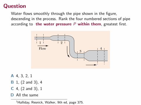
QuestionWater flows smoothly through the pipe shown in the figure,descending in the process. Rank the four numbered sections of pipeaccording to the water pressure P within them, greatest first.
37514-10 B E R NOU LLI ’S EQUATIONPART 2
Proof of Bernoulli’s EquationLet us take as our system the entire volume of the (ideal) fluid shown in Fig. 14-19.We shall apply the principle of conservation of energy to this system asit moves from its initial state (Fig. 14-19a) to its final state (Fig. 14-19b). The fluidlying between the two vertical planes separated by a distance L in Fig. 14-19 doesnot change its properties during this process; we need be concerned only withchanges that take place at the input and output ends.
First, we apply energy conservation in the form of the work–kinetic energytheorem,
W ! "K, (14-31)
which tells us that the change in the kinetic energy of our system must equal thenet work done on the system. The change in kinetic energy results from thechange in speed between the ends of the tube and is
, (14-32)
in which "m (! r "V) is the mass of the fluid that enters at the input end andleaves at the output end during a small time interval "t.
The work done on the system arises from two sources. The work Wg done bythe gravitational force on the fluid of mass "m during the vertical lift ofthe mass from the input level to the output level is
Wg ! #"m g(y2 # y1)
! #rg "V(y2 # y1). (14-33)
This work is negative because the upward displacement and the downward gravi-tational force have opposite directions.
Work must also be done on the system (at the input end) to push the enteringfluid into the tube and by the system (at the output end) to push forward the fluidthat is located ahead of the emerging fluid. In general, the work done by a forceof magnitude F, acting on a fluid sample contained in a tube of area A to movethe fluid through a distance "x, is
F "x ! ( pA)("x) ! p(A "x) ! p "V.
The work done on the system is then p1 "V, and the work done by the systemis #p2 "V.Their sum Wp is
Wp ! #p2 "V $ p1 "V
! #( p2 # p1) "V. (14-34)
The work–kinetic energy theorem of Eq. 14-31 now becomes
W ! Wg $ Wp ! "K.
Substituting from Eqs. 14-32, 14-33, and 14-34 yields
.
This, after a slight rearrangement, matches Eq. 14-28, which we set out to prove.
#%g "V(y2 # y1) # "V(p2 # p1) ! 12% "V(v2
2 # v21)
("m g:)
! 12% "V(v2
2 # v21)
"K ! 12"m v2
2 # 12"m v2
1
CHECKPOINT 4
Water flows smoothly through thepipe shown in the figure, descendingin the process. Rank the four num-bered sections of pipe according to(a) the volume flow rate RV throughthem, (b) the flow speed v throughthem, and (c) the water pressure pwithin them, greatest first.
1
Flow
2
34
halliday_c14_359-385hr.qxd 26-10-2009 21:40 Page 375
A 4, 3, 2, 1
B 1, (2 and 3), 4
C 4, (2 and 3), 1
D All the same
1Halliday, Resnick, Walker, 9th ed, page 375.
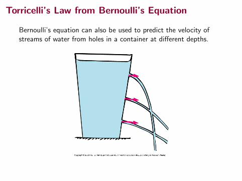
Torricelli’s Law from Bernoulli’s Equation
Bernoulli’s equation can also be used to predict the velocity ofstreams of water from holes in a container at different depths.
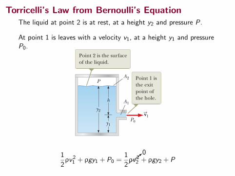
Torricelli’s Law from Bernoulli’s EquationThe liquid at point 2 is at rest, at a height y2 and pressure P.
At point 1 is leaves with a velocity v1, at a height y1 and pressureP0.
432 Chapter 14 Fluid Mechanics
Example 14.8 The Venturi Tube
The horizontal constricted pipe illustrated in Figure 14.19, known as a Venturi tube, can be used to measure the flow speed of an incompressible fluid. Determine the flow speed at point 2 of Figure 14.19a if the pressure difference P1 2 P2 is known.
Conceptualize Bernoulli’s equation shows how the pressure of an ideal fluid decreases as its speed increases. Therefore, we should be able to calibrate a device to give us the fluid speed if we can measure pressure.
Categorize Because the problem states that the fluid is incom-pressible, we can categorize it as one in which we can use the equation of continuity for fluids and Bernoulli’s equation.
S O L U T I O N
Analyze Apply Equation 14.8 to points 1 and 2, noting that y1 5 y2 because the pipe is horizontal:
(1) P1 1 12rv1
2 5 P2 1 12rv2
2
Solve the equation of continuity for v1: v1 5A2
A1 v2
a
P1 P2
A2
A1
v1S v2
S!
"
b
© C
enga
ge Le
arni
ng/C
harle
s D. W
inte
rs
Figure 14.19 (Example 14.8) (a) Pressure P1 is greater than pressure P2 because v1 , v2. This device can be used to measure the speed of fluid flow. (b) A Venturi tube, located at the top of the photograph. The higher level of fluid in the middle column shows that the pressure at the top of the column, which is in the constricted region of the Venturi tube, is lower.
Finalize From the design of the tube (areas A1 and A2) and measurements of the pressure difference P1 2 P2, we can calculate the speed of the fluid with this equation. To see the relationship between fluid speed and pressure differ-ence, place two empty soda cans on their sides about 2 cm apart on a table. Gently blow a stream of air horizontally between the cans and watch them roll together slowly due to a modest pressure difference between the stagnant air on their outside edges and the moving air between them. Now blow more strongly and watch the increased pressure dif-ference move the cans together more rapidly.
Substitute this expression into Equation (1): P1 1 12raA2
A1b2
v22 5 P2 1 1
2rv22
Solve for v2: v2 5 A1Å 2 1P1 2 P2 2r 1A1
2 2 A22 2
Example 14.9 Torricelli’s Law
An enclosed tank containing a liquid of density r has a hole in its side at a distance y1 from the tank’s bottom (Fig. 14.20). The hole is open to the atmosphere, and its diameter is much smaller than the diameter of the tank. The air above the liquid is maintained at a pressure P. Determine the speed of the liquid as it leaves the hole when the liquid’s level is a distance h above the hole.
Conceptualize Imagine that the tank is a fire extinguisher. When the hole is opened, liquid leaves the hole with a certain speed. If the pressure P at the top of the liquid is increased, the liquid leaves with a higher speed. If the pressure P falls too low, the liquid leaves with a low speed and the extinguisher must be replaced.
AM
S O L U T I O N
A2
A1
P0
h
P
y2
y1
v1S
Point 2 is the surface of the liquid.
Point 1 is the exit point of the hole.
Figure 14.20 (Example 14.9) A liquid leaves a hole in a tank at speed v1.1
2ρv21 + ρgy1 + P0 =
1
2���>
0ρv22 + ρgy2 + P
Torricelli’s Law from Bernoulli’s Equation
432 Chapter 14 Fluid Mechanics
Example 14.8 The Venturi Tube
The horizontal constricted pipe illustrated in Figure 14.19, known as a Venturi tube, can be used to measure the flow speed of an incompressible fluid. Determine the flow speed at point 2 of Figure 14.19a if the pressure difference P1 2 P2 is known.
Conceptualize Bernoulli’s equation shows how the pressure of an ideal fluid decreases as its speed increases. Therefore, we should be able to calibrate a device to give us the fluid speed if we can measure pressure.
Categorize Because the problem states that the fluid is incom-pressible, we can categorize it as one in which we can use the equation of continuity for fluids and Bernoulli’s equation.
S O L U T I O N
Analyze Apply Equation 14.8 to points 1 and 2, noting that y1 5 y2 because the pipe is horizontal:
(1) P1 1 12rv1
2 5 P2 1 12rv2
2
Solve the equation of continuity for v1: v1 5A2
A1 v2
a
P1 P2
A2
A1
v1S v2
S!
"
b
© C
enga
ge Le
arni
ng/C
harle
s D. W
inte
rs
Figure 14.19 (Example 14.8) (a) Pressure P1 is greater than pressure P2 because v1 , v2. This device can be used to measure the speed of fluid flow. (b) A Venturi tube, located at the top of the photograph. The higher level of fluid in the middle column shows that the pressure at the top of the column, which is in the constricted region of the Venturi tube, is lower.
Finalize From the design of the tube (areas A1 and A2) and measurements of the pressure difference P1 2 P2, we can calculate the speed of the fluid with this equation. To see the relationship between fluid speed and pressure differ-ence, place two empty soda cans on their sides about 2 cm apart on a table. Gently blow a stream of air horizontally between the cans and watch them roll together slowly due to a modest pressure difference between the stagnant air on their outside edges and the moving air between them. Now blow more strongly and watch the increased pressure dif-ference move the cans together more rapidly.
Substitute this expression into Equation (1): P1 1 12raA2
A1b2
v22 5 P2 1 1
2rv22
Solve for v2: v2 5 A1Å 2 1P1 2 P2 2r 1A1
2 2 A22 2
Example 14.9 Torricelli’s Law
An enclosed tank containing a liquid of density r has a hole in its side at a distance y1 from the tank’s bottom (Fig. 14.20). The hole is open to the atmosphere, and its diameter is much smaller than the diameter of the tank. The air above the liquid is maintained at a pressure P. Determine the speed of the liquid as it leaves the hole when the liquid’s level is a distance h above the hole.
Conceptualize Imagine that the tank is a fire extinguisher. When the hole is opened, liquid leaves the hole with a certain speed. If the pressure P at the top of the liquid is increased, the liquid leaves with a higher speed. If the pressure P falls too low, the liquid leaves with a low speed and the extinguisher must be replaced.
AM
S O L U T I O N
A2
A1
P0
h
P
y2
y1
v1S
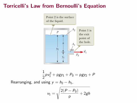
Point 2 is the surface of the liquid.
Point 1 is the exit point of the hole.
Figure 14.20 (Example 14.9) A liquid leaves a hole in a tank at speed v1.
1
2ρv21 + ρgy1 + P0 = ρgy2 + P
Rearranging, and using y = h2 − h1,
v1 =
√2(P − P0)
ρ+ 2gh
Torricelli’s Law from Bernoulli’s Equation
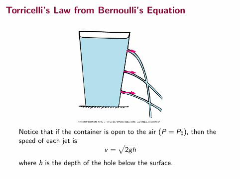
Notice that if the container is open to the air (P = P0), then thespeed of each jet is
v =√
2gh
where h is the depth of the hole below the surface.
Summary
• fluid dynamics
• the continuity equation
• Bernoulli’s equation
• Torricelli’s law (?)
Test Wednesday, April 22, in class.