Fluids Buoyancy Fluid Dynamics Bernoulli's...
53
Fluids Buoyancy Fluid Dynamics Bernoulli’s Equation Lana Sheridan De Anza College April 12, 2017
Transcript of Fluids Buoyancy Fluid Dynamics Bernoulli's...
FluidsBuoyancy
Fluid DynamicsBernoulli’s Equation
Lana Sheridan
De Anza College
April 12, 2017
Last time
• pressure and depth
• Pascal’s principle
• measurements of pressure
Overview
• buoyancy and Archimedes’ principle
• fluid dynamics
Manometer
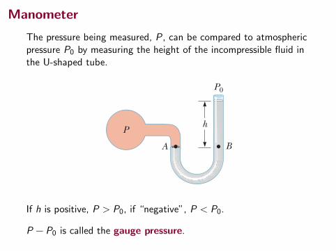
The pressure being measured, P, can be compared to atmosphericpressure P0 by measuring the height of the incompressible fluid inthe U-shaped tube.
14.4 Buoyant Forces and Archimedes’s Principle 423
14.3 Pressure MeasurementsDuring the weather report on a television news program, the barometric pressure is often provided. This reading is the current local pressure of the atmosphere, which varies over a small range from the standard value provided earlier. How is this pres-sure measured? One instrument used to measure atmospheric pressure is the common barom-eter, invented by Evangelista Torricelli (1608–1647). A long tube closed at one end is filled with mercury and then inverted into a dish of mercury (Fig. 14.6a). The closed end of the tube is nearly a vacuum, so the pressure at the top of the mer-cury column can be taken as zero. In Figure 14.6a, the pressure at point A, due to the column of mercury, must equal the pressure at point B, due to the atmo-sphere. If that were not the case, there would be a net force that would move mer-cury from one point to the other until equilibrium is established. Therefore, P0 5 rHggh, where rHg is the density of the mercury and h is the height of the mercury column. As atmospheric pressure varies, the height of the mercury column varies, so the height can be calibrated to measure atmospheric pressure. Let us determine the height of a mercury column for one atmosphere of pressure, P0 5 1 atm 5 1.013 3 105 Pa:
P0 5 rHggh S h 5P0
rHgg 51.013 3 105 Pa113.6 3 103 kg/m3 2 19.80 m/s2 2 5 0.760 m
Based on such a calculation, one atmosphere of pressure is defined to be the pres-sure equivalent of a column of mercury that is exactly 0.760 0 m in height at 08C. A device for measuring the pressure of a gas contained in a vessel is the open-tube manometer illustrated in Figure 14.6b. One end of a U-shaped tube containing a liquid is open to the atmosphere, and the other end is connected to a container of gas at pressure P. In an equilibrium situation, the pressures at points A and B must be the same (otherwise, the curved portion of the liquid would experience a net force and would accelerate), and the pressure at A is the unknown pressure of the gas. Therefore, equating the unknown pressure P to the pressure at point B, we see that P 5 P0 1 rgh. Again, we can calibrate the height h to the pressure P. The difference in the pressures in each part of Figure 14.6 (that is, P 2 P0) is equal to rgh. The pressure P is called the absolute pressure, and the difference P 2 P0 is called the gauge pressure. For example, the pressure you measure in your bicycle tire is gauge pressure.
Q uick Quiz 14.3 Several common barometers are built, with a variety of fluids. For which of the following fluids will the column of fluid in the barometer be the highest? (a) mercury (b) water (c) ethyl alcohol (d) benzene
14.4 Buoyant Forces and Archimedes’s PrincipleHave you ever tried to push a beach ball down under water (Fig. 14.7a, p. 424)? It is extremely difficult to do because of the large upward force exerted by the water on the ball. The upward force exerted by a fluid on any immersed object is called
The total force on the dam is equal to the product of the average pressure and the area of the face of the dam:
F 5 PavgA 5 112rgH 2 1Hw 2 5 1
2rgwH 2
which is the same result we obtained using calculus.
a
P ! 0
P
P0
P0
A B
h
h
A B
b
Figure 14.6 Two devices for measuring pressure: (a) a mercury barometer and (b) an open-tube manometer.
▸ 14.4 c o n t i n u e d
If h is positive, P > P0, if “negative”, P < P0.
P − P0 is called the gauge pressure.
Buoyancy
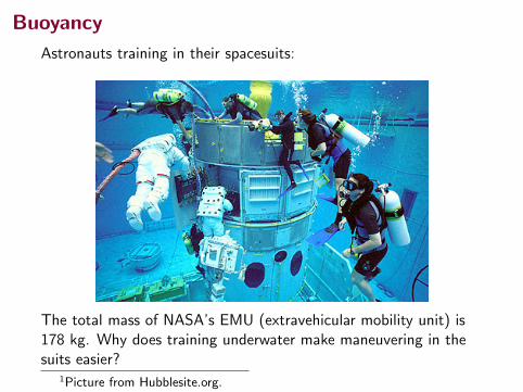
Astronauts training in their spacesuits:
The total mass of NASA’s EMU (extravehicular mobility unit) is178 kg. Why does training underwater make maneuvering in thesuits easier?
1Picture from Hubblesite.org.
Buoyancy
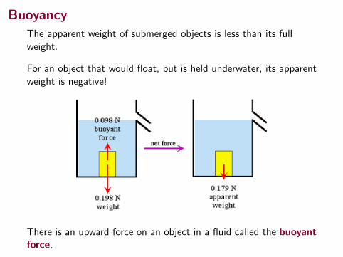
The apparent weight of submerged objects is less than its fullweight.
For an object that would float, but is held underwater, its apparentweight is negative!
There is an upward force on an object in a fluid called the buoyantforce.
Buoyancy
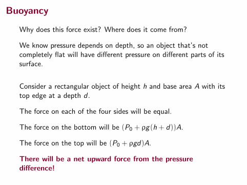
Why does this force exist? Where does it come from?
We know pressure depends on depth, so an object that’s notcompletely flat will have different pressure on different parts of itssurface.
Consider a rectangular object of height h and base area A with itstop edge at a depth d .
The force on each of the four sides will be equal.
The force on the bottom will be (P0 + ρg(h + d))A.
The force on the top will be (P0 + ρgd)A.
There will be a net upward force from the pressuredifference!
Buoyancy
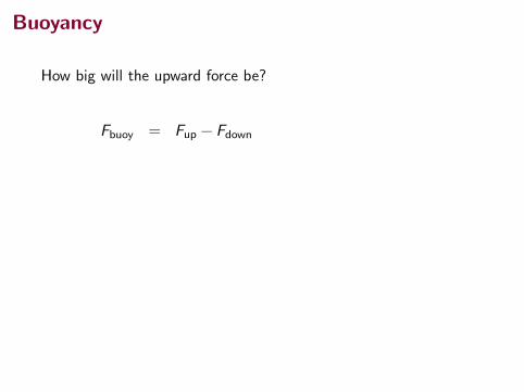
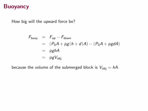
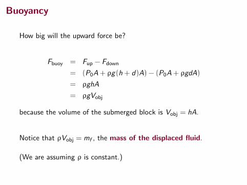
How big will the upward force be?
Fbuoy = Fup − Fdown
= (P0A+ ρg(h + d)A) − (P0A+ ρgdA)
= ρghA
= ρgVobj
because the volume of the submerged block is Vobj = hA.
Notice that ρVobj = mf , the mass of the displaced fluid.
(We are assuming ρ is constant.)
Buoyancy
How big will the upward force be?
Fbuoy = Fup − Fdown
= (P0A+ ρg(h + d)A) − (P0A+ ρgdA)
= ρghA
= ρgVobj
because the volume of the submerged block is Vobj = hA.
Notice that ρVobj = mf , the mass of the displaced fluid.
(We are assuming ρ is constant.)
Buoyancy
How big will the upward force be?
Fbuoy = Fup − Fdown
= (P0A+ ρg(h + d)A) − (P0A+ ρgdA)
= ρghA
= ρgVobj
because the volume of the submerged block is Vobj = hA.
Notice that ρVobj = mf , the mass of the displaced fluid.
(We are assuming ρ is constant.)
Buoyancy and Archimedes’ Principle
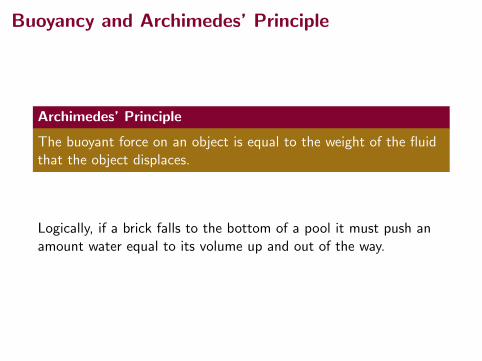
Archimedes’ Principle
The buoyant force on an object is equal to the weight of the fluidthat the object displaces.
Logically, if a brick falls to the bottom of a pool it must push anamount water equal to its volume up and out of the way.
Buoyancy and Archimedes’ Principle
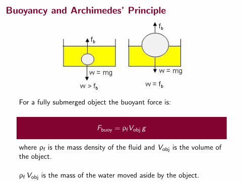
For a fully submerged object the buoyant force is:
Fbuoy = ρfVobj g
where ρf is the mass density of the fluid and Vobj is the volume ofthe object.
ρf Vobj is the mass of the water moved aside by the object.
Buoyancy and Archimedes’ Principle
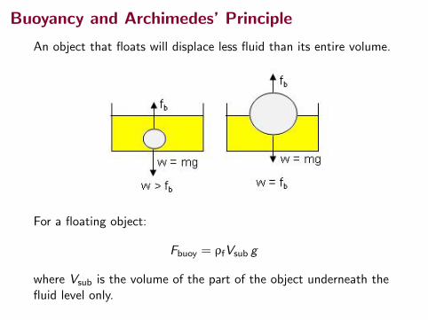
An object that floats will displace less fluid than its entire volume.
For a floating object:
Fbuoy = ρfVsub g
where Vsub is the volume of the part of the object underneath thefluid level only.
Sinking and Floating
Will a particular object sink or float in a particular fluid?
• If the object is less dense than the fluid it will float.
• If the object is more dense than the fluid it will sink.
• If the object and the fluid have the same density if will neitherfloat or sink, but drift at equilibrium.
Sinking and Floating
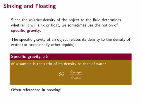
Since the relative density of the object to the fluid determineswhether it will sink or float, we sometimes use the notion ofspecific gravity.
The specific gravity of an object relates its density to the density ofwater (or occasionally other liquids):
Specific gravity, SG
of a sample is the ratio of its density to that of water.
SG =ρsample
ρwater
Often referenced in brewing!
Sinking and Floating
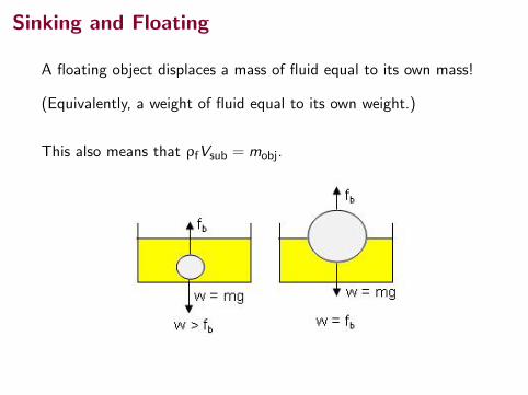
A floating object displaces a mass of fluid equal to its own mass!
(Equivalently, a weight of fluid equal to its own weight.)
This also means that ρfVsub = mobj.
Questions
Military ships are often compared by their displacements, theweight (or mass, depending on context) of water they displace.
The USS Enterprise was an aircraft carrier (now decommissioned).
Displacement: 94,781 tonnes (metric tons), fully loaded.
1 tonne = 1000 kg
What is the mass of the fully loaded USS Enterprise in kgs?
Another Problem1
Your friend of mass 100 kg can just barely float in fresh water.Calculate her approximate volume. 0.1 m3
2Hewitt, page 246.
Questions
Military ships are often compared by their displacements, theweight (or mass, depending on context) of water they displace.
The USS Enterprise was an aircraft carrier (now decommissioned).
Displacement: 94,781 tonnes (metric tons), fully loaded.
1 tonne = 1000 kg
What is the mass of the fully loaded USS Enterprise in kgs?
Another Problem1
Your friend of mass 100 kg can just barely float in fresh water.Calculate her approximate volume.
0.1 m3
2Hewitt, page 246.
Questions
Military ships are often compared by their displacements, theweight (or mass, depending on context) of water they displace.
The USS Enterprise was an aircraft carrier (now decommissioned).
Displacement: 94,781 tonnes (metric tons), fully loaded.
1 tonne = 1000 kg
What is the mass of the fully loaded USS Enterprise in kgs?
Another Problem1
Your friend of mass 100 kg can just barely float in fresh water.Calculate her approximate volume. 0.1 m3
2Hewitt, page 246.
Question
Quick Quiz 14.42 You are shipwrecked and floating in the middleof the ocean on a raft. Your cargo on the raft includes a treasurechest full of gold that you found before your ship sank, and theraft is just barely afloat. To keep you floating as high as possible inthe water, should you(i) leave the treasure chest on top of the raft,(ii) secure the treasure chest to the underside of the raft, or(iii) hang the treasure chest in the water with a rope attached tothe raft?(Assume throwing the treasure chest overboard is not an optionyou wish to consider.)
A option (ii) is the best
B option (iii) is the best
C options (ii) and (iii) would be the same, better than (i)
D All would be the same
2Serway & Jewett, page 425.
Buoyancy in Air
Buoyancy in air works the same way as in liquids:
Fbuoy = ρfVobj g
If an object is less dense than air, it will float upwards.
However, in the atmosphere, the density of air varies with height.
Buoyancy in Air
1Photo by Derek Jensen, Wikipedia.
Buoyancy in Air
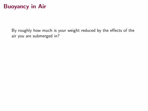
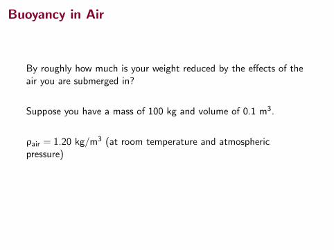
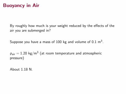
By roughly how much is your weight reduced by the effects of theair you are submerged in?
Suppose you have a mass of 100 kg and volume of 0.1 m3.
ρair = 1.20 kg/m3 (at room temperature and atmosphericpressure)
About 1.18 N.
Buoyancy in Air
By roughly how much is your weight reduced by the effects of theair you are submerged in?
Suppose you have a mass of 100 kg and volume of 0.1 m3.
ρair = 1.20 kg/m3 (at room temperature and atmosphericpressure)
About 1.18 N.
Buoyancy in Air
By roughly how much is your weight reduced by the effects of theair you are submerged in?
Suppose you have a mass of 100 kg and volume of 0.1 m3.
ρair = 1.20 kg/m3 (at room temperature and atmosphericpressure)
About 1.18 N.
Fluid Dynamics
When fluids are in motion, their behavior can be very complex.
We will only consider smooth, laminar flow.
Laminar flow is composed of streamlines that do not cross or curlinto vortices.
Streamline
The lines traced out by the velocities of individual particles overtime. Streamlines are always tangent to the velocity vectors in theflow.
Fluid Dynamics
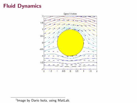
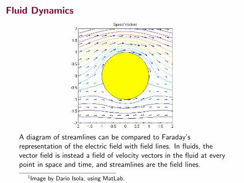
A diagram of streamlines can be compared to Faraday’srepresentation of the electric field with field lines. In fluids, thevector field is instead a field of velocity vectors in the fluid at everypoint in space and time, and streamlines are the field lines.
1Image by Dario Isola, using MatLab.
Fluid Dynamics
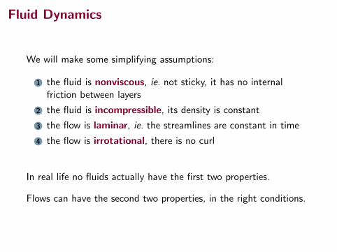
We will make some simplifying assumptions:
1 the fluid is nonviscous, ie. not sticky, it has no internalfriction between layers
2 the fluid is incompressible, its density is constant
3 the flow is laminar, ie. the streamlines are constant in time
4 the flow is irrotational, there is no curl
In real life no fluids actually have the first two properties.
Flows can have the second two properties, in the right conditions.
Fluid Dynamics
We will make some simplifying assumptions:
1 the fluid is nonviscous, ie. not sticky, it has no internalfriction between layers
2 the fluid is incompressible, its density is constant
3 the flow is laminar, ie. the streamlines are constant in time
4 the flow is irrotational, there is no curl
In real life no fluids actually have the first two properties.
Flows can have the second two properties, in the right conditions.
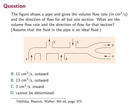
Question
The figure shows a pipe and gives the volume flow rate (in cm3/s)and the direction of flow for all but one section. What are thevolume flow rate and the direction of flow for that section?(Assume that the fluid in the pipe is an ideal fluid.)
37314-9 TH E EQUATION OF CONTI N U ITYPART 2
We can rewrite Eq. 14-23 as
RV ! Av ! a constant (volume flow rate, equation of continuity), (14-24)
in which RV is the volume flow rate of the fluid (volume past a given point perunit time). Its SI unit is the cubic meter per second (m3/s). If the density r of thefluid is uniform, we can multiply Eq. 14-24 by that density to get the mass flowrate Rm (mass per unit time):
Rm ! rRV ! rAv ! a constant (mass flow rate). (14-25)
The SI unit of mass flow rate is the kilogram per second (kg/s). Equation 14-25says that the mass that flows into the tube segment of Fig. 14-15 each second mustbe equal to the mass that flows out of that segment each second.
CHECKPOINT 3
The figure shows a pipe and gives the volume flow rate (in cm3/s) and the di-rection of flow for all but one section. What are the volume flow rate and thedirection of flow for that section?
4 8
2 56
4
Sample Problem
A water stream narrows as it falls
Figure 14-18 shows how the stream of water emerging froma faucet “necks down” as it falls. This change in the horizontalcross-sectional area is characteristic of any laminar (non-turbulant) falling stream because the gravitational forceincreases the speed of the stream. Here the indicatedcross-sectional areas are A0 ! 1.2 cm2 and A ! 0.35 cm2.The two levels are separated by a vertical distance h ! 45 mm.What is the volume flow rate from the tap?
KEY I DEA
Fig. 14-18 As water falls from a tap, its speedincreases. Because the volume flow rate must bethe same at all horizontal cross sections of thestream, the stream must “neck down” (narrow).
h
A0
A
The volume flow persecond here mustmatch ...
... the volume flowper second here.
The volume flow rate through the higher cross section mustbe the same as that through the lower cross section.
Calculations: From Eq. 14-24, we have
A0v0 ! Av, (14-26)
where v0 and v are the water speeds at the levels correspond-ing to A0 and A. From Eq. 2-16 we can also write, because thewater is falling freely with acceleration g,
v2 ! v20 " 2gh. (14-27)
Eliminating v between Eqs. 14-26 and 14-27 and solving forv0, we obtain
! 0.286 m/s ! 28.6 cm/s.
From Eq. 14-24, the volume flow rate RV is thenRV ! A0v0 ! (1.2 cm2)(28.6 cm/s)
! 34 cm3/s. (Answer)
! A (2)(9.8 m/s2)(0.045 m)(0.35 cm2)2
(1.2 cm2)2 # (0.35 cm2)2
v0 ! A 2ghA2
A20 # A2
Additional examples, video, and practice available at WileyPLUS
halliday_c14_359-385hr.qxd 26-10-2009 21:40 Page 373
A 11 cm3/s, outward
B 13 cm3/s, outward
C 3 cm3/s, inward
D cannot be determined
1Halliday, Resnick, Walker, 9th ed, page 373.
Bernoulli’s Principle
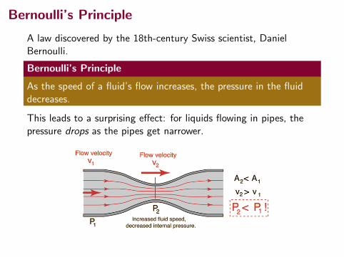
A law discovered by the 18th-century Swiss scientist, DanielBernoulli.
Bernoulli’s Principle
As the speed of a fluid’s flow increases, the pressure in the fluiddecreases.
This leads to a surprising effect: for liquids flowing in pipes, thepressure drops as the pipes get narrower.
Bernoulli’s Principle
Why should this principle hold? Where does it come from?
Actually, it just comes from the conservation of energy, and anassumption that the fluid is incompressible.3
Consider a fixed volume of fluid, V .
In a narrower pipe, this volume flows by a particular point 1 intime ∆t.
However, it must push the same volume of fluid past a point 2 inthe same time. If the pipe is wider at point 2, it flows more slowly.
1Something similar can be argued for compressible fluids also.
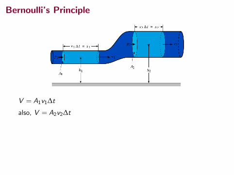
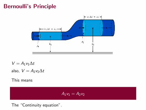
Bernoulli’s Principle
V = A1v1∆t
also, V = A2v2∆t
This means
A1v1 = A2v2
The “Continuity equation”.
Bernoulli’s Principle
V = A1v1∆t
also, V = A2v2∆t
This means
A1v1 = A2v2
The “Continuity equation”.
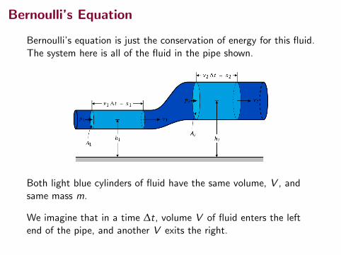
Bernoulli’s Equation
Bernoulli’s equation is just the conservation of energy for this fluid.The system here is all of the fluid in the pipe shown.
Both light blue cylinders of fluid have the same volume, V , andsame mass m.
We imagine that in a time ∆t, volume V of fluid enters the leftend of the pipe, and another V exits the right.
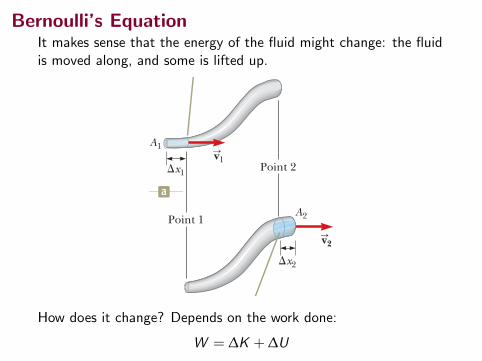
Bernoulli’s EquationIt makes sense that the energy of the fluid might change: the fluidis moved along, and some is lifted up.
428 Chapter 14 Fluid Mechanics
The path taken by a fluid particle under steady flow is called a streamline. The velocity of the particle is always tangent to the streamline as shown in Figure 14.15. A set of streamlines like the ones shown in Figure 14.15 form a tube of flow. Fluid particles cannot flow into or out of the sides of this tube; if they could, the stream-lines would cross one another. Consider ideal fluid flow through a pipe of nonuniform size as illustrated in Fig-ure 14.16. Let’s focus our attention on a segment of fluid in the pipe. Figure 14.16a shows the segment at time t 5 0 consisting of the gray portion between point 1 and point 2 and the short blue portion to the left of point 1. At this time, the fluid in the short blue portion is flowing through a cross section of area A1 at speed v1. During the time interval Dt, the small length Dx1 of fluid in the blue portion moves past point 1. During the same time interval, fluid at the right end of the segment moves past point 2 in the pipe. Figure 14.16b shows the situation at the end of the time interval Dt. The blue portion at the right end represents the fluid that has moved past point 2 through an area A2 at a speed v2. The mass of fluid contained in the blue portion in Figure 14.16a is given by m1 5 rA1 Dx1 5 rA1v1 Dt, where r is the (unchanging) density of the ideal fluid. Similarly, the fluid in the blue portion in Figure 14.16b has a mass m2 5 rA2 Dx2 5 rA2v2 Dt. Because the fluid is incompressible and the flow is steady, however, the mass of fluid that passes point 1 in a time interval Dt must equal the mass that passes point 2 in the same time interval. That is, m1 5 m2 or rA1v1 Dt 5 rA2v2 Dt, which means that
A1v1 5 A2v2 5 constant (14.7)
This expression is called the equation of continuity for fluids. It states that the product of the area and the fluid speed at all points along a pipe is constant for an incompressible fluid. Equation 14.7 shows that the speed is high where the tube is constricted (small A) and low where the tube is wide (large A). The product Av, which has the dimensions of volume per unit time, is called either the volume flux or the flow rate. The condition Av 5 constant is equivalent to the statement that the vol-ume of fluid that enters one end of a tube in a given time interval equals the volume leaving the other end of the tube in the same time interval if no leaks are present. You demonstrate the equation of continuity each time you water your garden with your thumb over the end of a garden hose as in Figure 14.17. By partially block-
Equation of Continuity Xfor Fluids
Figure 14.17 The speed of water spraying from the end of a garden hose increases as the size of the opening is decreased with the thumb.©
Cen
gage
Lea
rnin
g/Ge
orge
Sem
ple
vS
At each point along its path, the particle’s velocity is tangent to the streamline.
Figure 14.15 A particle in laminar flow follows a streamline.
v2
v1
At t ! 0, fluid in the blueportion is moving pastpoint 1 at velocity v1.
After a time interval "t,the fluid in the blue portion is moving past point 2 at velocity v2.
"x1
"x2
Point 2
Point 1
A1
A2
a
S
S
S
S
b
Figure 14.16 A fluid moving with steady flow through a pipe of varying cross-sectional area. (a) At t 5 0, the small blue-colored portion of the fluid at the left is moving through area A1. (b) After a time interval Dt, the blue-colored portion shown here is that fluid that has moved through area A2.
How does it change? Depends on the work done:
W = ∆K + ∆U
Bernoulli’s Equation
430 Chapter 14 Fluid Mechanics
14.6 Bernoulli’s EquationYou have probably experienced driving on a highway and having a large truck pass you at high speed. In this situation, you may have had the frightening feeling that your car was being pulled in toward the truck as it passed. We will investigate the origin of this effect in this section. As a fluid moves through a region where its speed or elevation above the Earth’s surface changes, the pressure in the fluid varies with these changes. The relationship between fluid speed, pressure, and elevation was first derived in 1738 by Swiss physicist Daniel Bernoulli. Consider the flow of a segment of an ideal fluid through a nonuniform pipe in a time interval Dt as illustrated in Figure 14.18. This figure is very similar to Figure 14.16, which we used to develop the continuity equation. We have added two features: the forces on the outer ends of the blue portions of fluid and the heights of these portions above the reference position y 5 0. The force exerted on the segment by the fluid to the left of the blue portion in Figure 14.18a has a magnitude P1A1. The work done by this force on the segment in a time interval Dt is W1 5 F1 Dx1 5 P1A1 Dx1 5 P1V, where V is the volume of the blue portion of fluid passing point 1 in Figure 14.18a. In a similar manner, the work done on the segment by the fluid to the right of the segment in the same time interval Dt is W2 5 2P2A2 Dx2 5 2P2V, where V is the volume of the blue portion of fluid passing point 2 in Figure 14.18b. (The volumes of the blue portions of fluid in Figures 14.18a and 14.18b are equal because the fluid is incompressible.) This work is negative because the force on the segment of fluid is to the left and the displace-ment of the point of application of the force is to the right. Therefore, the net work done on the segment by these forces in the time interval Dt is
W 5 (P1 2 P2)V
Finalize The time interval for the element of water to fall to the ground is unchanged if the projection speed is changed because the projection is horizontal. Increasing the projection speed results in the water hitting the ground farther from the end of the hose, but requires the same time interval to strike the ground.
y1
y2
The pressure atpoint 1 is P1.
P1A1 i
The pressure atpoint 2 is P2. v2
v1!x1
!x2
Point 2
Point 1a
S
S
"P2A2 i
ˆ
ˆ
b
Figure 14.18 A fluid in laminar flow through a pipe. (a) A segment of the fluid at time t 5 0. A small portion of the blue-colored fluid is at height y1 above a reference position. (b) After a time interval Dt, the entire segment has moved to the right. The blue-colored por-tion of the fluid is that which has passed point 2 and is at height y2.
▸ 14.7 c o n t i n u e d
Daniel BernoulliSwiss physicist (1700–1782)Bernoulli made important discoveries in fluid dynamics. Bernoulli’s most famous work, Hydrodynamica, was published in 1738; it is both a theoreti-cal and a practical study of equilibrium, pressure, and speed in fluids. He showed that as the speed of a fluid increases, its pressure decreases. Referred to as “Bernoulli’s principle,” Bernoulli’s work is used to produce a partial vacuum in chemical laboratories by connecting a vessel to a tube through which water is running rapidly.
. iS
tock
phot
o.co
m/Z
U_09
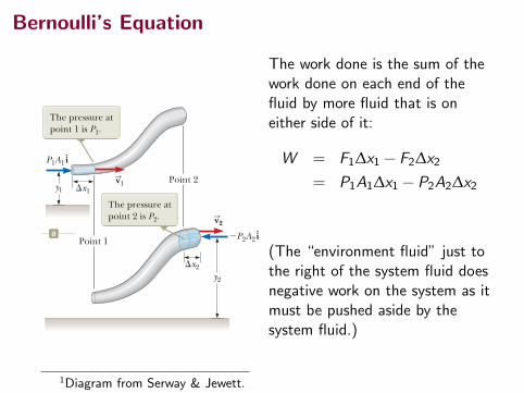
The work done is the sum of thework done on each end of thefluid by more fluid that is oneither side of it:
W = F1∆x1 − F2∆x2
= P1A1∆x1 − P2A2∆x2
(The “environment fluid” just tothe right of the system fluid doesnegative work on the system as itmust be pushed aside by thesystem fluid.)
1Diagram from Serway & Jewett.
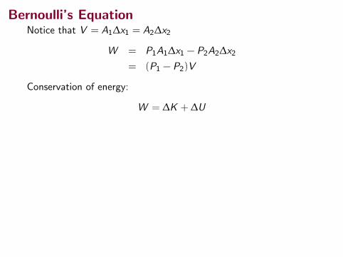
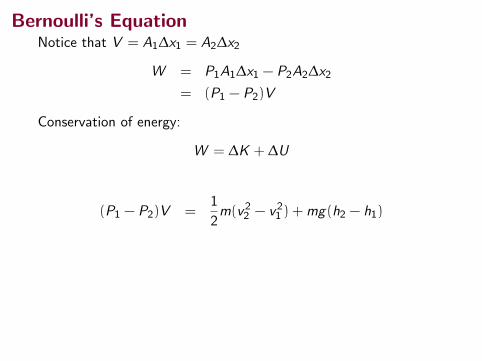
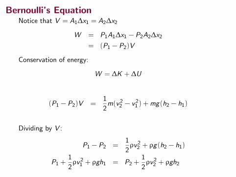
Bernoulli’s EquationNotice that V = A1∆x1 = A2∆x2
W = P1A1∆x1 − P2A2∆x2
= (P1 − P2)V
Conservation of energy:
W = ∆K + ∆U
(P1 − P2)V =1
2m(v22 − v21 ) +mg(h2 − h1)
Dividing by V :
P1 − P2 =1
2ρv22 + ρg(h2 − h1)
P1 +1
2ρv21 + ρgh1 = P2 +
1
2ρv22 + ρgh2
Bernoulli’s EquationNotice that V = A1∆x1 = A2∆x2
W = P1A1∆x1 − P2A2∆x2
= (P1 − P2)V
Conservation of energy:
W = ∆K + ∆U
(P1 − P2)V =1
2m(v22 − v21 ) +mg(h2 − h1)
Dividing by V :
P1 − P2 =1
2ρv22 + ρg(h2 − h1)
P1 +1
2ρv21 + ρgh1 = P2 +
1
2ρv22 + ρgh2
Bernoulli’s EquationNotice that V = A1∆x1 = A2∆x2
W = P1A1∆x1 − P2A2∆x2
= (P1 − P2)V
Conservation of energy:
W = ∆K + ∆U
(P1 − P2)V =1
2m(v22 − v21 ) +mg(h2 − h1)
Dividing by V :
P1 − P2 =1
2ρv22 + ρg(h2 − h1)
P1 +1
2ρv21 + ρgh1 = P2 +
1
2ρv22 + ρgh2
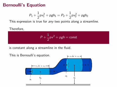
Bernoulli’s Equation
P1 +1
2ρv21 + ρgh1 = P2 +
1
2ρv22 + ρgh2
This expression is true for any two points along a streamline.
Therefore,
P +1
2ρv2 + ρgh = const
is constant along a streamline in the fluid.
This is Bernoulli’s equation.
Bernoulli’s Equation
P +1
2ρv2 + ρgh = const
Even though we derived this expression for the case of anincompressible fluid, this is also true (to first order) forcompressible fluids, like air and other gases.
The constraint is that the densities should not vary too much fromthe ambient density ρ.
Bernoulli’s Principle from Bernoulli’s Equation
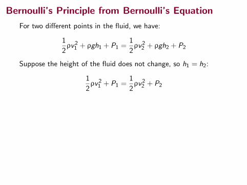
For two different points in the fluid, we have:
1
2ρv21 + ρgh1 + P1 =
1
2ρv22 + ρgh2 + P2
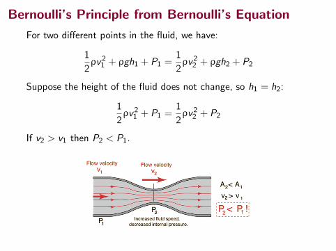
Suppose the height of the fluid does not change, so h1 = h2:
1
2ρv21 + P1 =
1
2ρv22 + P2
If v2 > v1 then P2 < P1.
Bernoulli’s Principle from Bernoulli’s Equation
For two different points in the fluid, we have:
1
2ρv21 + ρgh1 + P1 =
1
2ρv22 + ρgh2 + P2
Suppose the height of the fluid does not change, so h1 = h2:
1
2ρv21 + P1 =
1
2ρv22 + P2
If v2 > v1 then P2 < P1.
Bernoulli’s Principle from Bernoulli’s Equation
For two different points in the fluid, we have:
1
2ρv21 + ρgh1 + P1 =
1
2ρv22 + ρgh2 + P2
Suppose the height of the fluid does not change, so h1 = h2:
1
2ρv21 + P1 =
1
2ρv22 + P2
If v2 > v1 then P2 < P1.
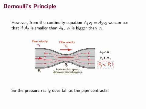
Bernoulli’s Principle
However, from the continuity equation A1v1 = A2v2 we can seethat if A2 is smaller than A1, v2 is bigger than v1.
So the pressure really does fall as the pipe contracts!
Summary
• buoyancy and Archimedes’ principle
• fluid dynamics
Test Tuesday, April 17, in class.
Collected Homework due Monday, April 16.
(Uncollected) Homework Serway & Jewett:
• Previous: Ch 14, onward from page 435. Probs: 25, 27, 29,35, 36, 65, 71, 73,(buoyancy questions)
• Ch 14, onward from page 435, OQs: 3, 5, 9, 13; CQs: 9, 14;Probs: 43, 49, 53, 85