Fluidized Bed Classroom Demonstration Unit
24
e University of Akron IdeaExchange@UAkron Williams Honors College, Honors Research Projects e Dr. Gary B. and Pamela S. Williams Honors College Spring 2019 Fluidized Bed Classroom Demonstration Unit eresa Chapa [email protected] Please take a moment to share how this work helps you through this survey. Your feedback will be important as we plan further development of our repository. Follow this and additional works at: hps://ideaexchange.uakron.edu/honors_research_projects Part of the Other Chemical Engineering Commons is Honors Research Project is brought to you for free and open access by e Dr. Gary B. and Pamela S. Williams Honors College at IdeaExchange@UAkron, the institutional repository of e University of Akron in Akron, Ohio, USA. It has been accepted for inclusion in Williams Honors College, Honors Research Projects by an authorized administrator of IdeaExchange@UAkron. For more information, please contact [email protected], [email protected]. Recommended Citation Chapa, eresa, "Fluidized Bed Classroom Demonstration Unit" (2019). Williams Honors College, Honors Research Projects. 861. hps://ideaexchange.uakron.edu/honors_research_projects/861
Transcript of Fluidized Bed Classroom Demonstration Unit

The University of AkronIdeaExchange@UAkronWilliams Honors College, Honors ResearchProjects
The Dr. Gary B. and Pamela S. Williams HonorsCollege
Spring 2019
Fluidized Bed Classroom Demonstration UnitTheresa [email protected]
Please take a moment to share how this work helps you through this survey. Your feedback will beimportant as we plan further development of our repository.Follow this and additional works at: https://ideaexchange.uakron.edu/honors_research_projects
Part of the Other Chemical Engineering Commons
This Honors Research Project is brought to you for free and open access by The Dr. Gary B. and Pamela S. WilliamsHonors College at IdeaExchange@UAkron, the institutional repository of The University of Akron in Akron, Ohio,USA. It has been accepted for inclusion in Williams Honors College, Honors Research Projects by an authorizedadministrator of IdeaExchange@UAkron. For more information, please contact [email protected],[email protected].
Recommended CitationChapa, Theresa, "Fluidized Bed Classroom Demonstration Unit" (2019). Williams Honors College, Honors ResearchProjects. 861.https://ideaexchange.uakron.edu/honors_research_projects/861


i
University of Akron
Honors Project
4200:497-002
Fluidized Bed Classroom Demonstration Unit
I affirm that this report represents work performed by me
and I assume full responsibility for originality,
comprehension, and accuracy of all aspects of the report.
Signature:
_ ___
Theresa Chapa
Date:
__April 26, 2019 _

ii
Abstract
Fluid and Thermal Operations is a 4th year chemical engineering course at the University of
Akron designed to introduce undergraduate students to the engineering and mathematical
concepts behind the operation of a fluidized bed. The purpose of this honors project is to design
and manufacture an inexpensive and portable unit that can be used in the classroom to visually
demonstrate three functions of a fluidized bed to students. The fluidized bed is manufactured
from items that can be purchased from a department or hardware store, is capable of being
transported by a single person to and from a classroom and is transparent to allow observers to
visually see all components of the unit while in operation. The department of chemical
engineering currently does not possess such a demonstration unit and the current faculty member
teaching the course was interested in having the ability to bring a fluidized bed to class. The unit
that results from this project will provide an educational benefit to undergraduate students in the
chemical and biochemical engineering department.

iii
Table of Contents
Executive Summary 1
Introduction 2
Design Description 3
Methodology 5
Results 8
Safety Information 12
Economics 13
Conclusions and Recommendations 14
Acknowledgements 15
References 15
Appendix 16

1
Executive Summary
The objective of this project is to design and build a portable demonstration unit that can be used
to show undergraduate chemical engineering students at the University of Akron the fundamental
functions of a fluidized bed. Fluidized beds are common units of operation found in the chemical
industry and there is a chance that students will be exposed to one during their time at the
university, while on co-op with a chemical company, or on the job as a full-time engineer. The
professor teaching Fluid and Thermal Operations in the chemical engineering department gave
the challenge to build the unit from commonly available parts, be light weight, inexpensive (low
budget), use a simple source of air flow and demonstrate more than one fluidization concept to
the undergraduate students.
The fluidized bed demonstration unit manufactured as a result of this honors project consists of
two identical beds made from number 2 SCH40 PVC pipe, 5/8in ID PVC tubing, ¾in brass gas
valves, ¾in brass 3-way splitter, and catching zone at the top of the beds cut from a 2L soda
bottle. The air source is a multispeed hair dryer connected to the unit via a cone shaped from a
polyethylene terephthalate (PET) soda bottle. The source of air flow is a cord retracting,
collapsible hair dryer at low power with the cold button taped down to prevent the dryer form
overheating. The gas valves control the air velocity through the beds. The total weight was 5.8lbs
with a height of 2ft 6.5in and length of 1ft 8.75in. The cost of materials was $152.10 not
including the donated oak wood and hardware used to build the frame.
The resulting fluidized bed from this project can demonstrate that as the diameter of particles
increases, the minimum air velocity required to fluidize the material increases. The impact of
particle size on minimum fluidization velocity is observed both with the small diameter particles
being loaded before the large ones and with the large diameter particles being loaded before the
small ones. The second property demonstrated is the ability for a fluidized bed to mix materials
of similar densities and size. The third function demonstrated was elutriation, where if the air
velocity is greater than the terminal velocity of the particles, the particles will leave the bed.

2
Introduction
Fluidized beds are utilized in many chemical processes that undergraduate chemical engineering
students will be introduced to in the classroom and possibly while completing a co-op for a
chemical company. One application is a fluidized-bed reactor, where the reactants flow up
through a solid catalyst, especially in a solid/gas reaction[1]. Fluidized beds can also be used for
drying solids, absorbing gasses, and catalytic cracking in the petroleum industry[1]. With
fluidized beds being prominent in the chemical industry, undergraduate students at the
University of Akron complete a Fluid and Thermal Operations (FLOPS) course where these
beds’ function and design are taught. The term fluidization refers to a fully suspended bed of
particles in a fluid, where the fluid is a liquid or gas. As fluid is introduced from the bottom of
the bed, the volume of particles expand to a new height. Elutriation refers to when the velocity of
fluid moving through the bed is great enough that the particles expand passed the length of the
bed, thus exiting the system through the top.
Do it yourself fluidized beds have been attempted by several people in the past, and some have
even documented their designs for the public to use for their own creation. Mark Rober, a
mechanical engineer who worked at NASA, built a fluidized sand hot tub (project titled Liquid
Sand Tub) and posted his designs on his personal website. His design required a very fine sand
and a compressor to provide enough air flow rate to suspend the sand in a small 0.5 ft3 box. After
several design changes, his tub utilized multiple pipes with small holes oriented down at the
bottom of the bed to provide the air and stop the pipelines from clogging [3]. The air distribution
method of Rober’s design inspired design choices in the completion of the project described in
this report.

3
Demonstration tools in the form of videos or physical examples have been used in undergraduate
classrooms to show students first hand how theory translates to actuality. One example is a
chemistry professor performing an experiment during lecture, or the Mass Transfer Operations
professor taking the class down to the department’s engineering lab to show students first hand
the components and controls for a tray distillation column. This report discusses a demonstration
unit built to show students three functions of a fluidized bed.
Design Description
The description that follows explains the physical components that make up the fluidized bed
demonstration unit found in the image below (Figure 1).
Figure 1: Image of the fluidized bed demonstration unit filled with varying diameter Styrofoam
beads. The unit consists of two identical beds using air from a hairdryer as the fluid source.

4
The source of air flow is a Conair 1875 Watt Cord-Keeper® with a retractable cord for compact
storage. Clear PVC tubing 5/8in ID and 7/8in OD was used to connect ¾in brass gas valves and
three-way splitter as well as direct air flow through the unit. The gas valves control the flow rate
of the air to the beds determined by the degree to which the valves are opened. To connect the
mouth of the hair dryer to the tubing, a cone made from the polyethylene terephthalate (PET) of
a 2-liter bottle to taper from the 2 1/8in diameter of the dryer to the ¾in brass male tubing
adapter. The two fluidized beds are made from number 2 schedule 40 clear PVC and are 11 7/8in
inches tall. The clear PVC allows observers to see inside, even with the slight blue tint. The
conical top of a PET soda bottle was used to connect the tubing to the pipe, secured with a two-
part epoxy adhesive. The adhesive will ensure the pipe and cone will not separate, the filter will
not move and bed will not leak air to the surroundings. To prevent the beads from elutriating
from the bed and making a mess, a second section of 4 1/4in PET soda bottle was added on top
of the PVC pipe. This increase in diameter reduces the air velocity, allowing the beads to fall
back into the PVC pipe. To keep the packing material from falling down into the tubing at the
bottom of the bed, the inner diameter of the PVC tube was cut from a sheet of blue 3M Filtrete
air cleaning filter. The meshing of the fibers provides many small pathways for the air to move
through while preventing the Styrofoam beads from falling down into the piping. The filter was
secured into the bottle adapter before the pipe was attached.
The entirety of the apparatus is set on a custom fabricated wooden frame to hold the unit upright
while operating and for easier transport (not included in the drawing). The joints of the frame are
held together with hot wood glue and reinforced with screws and nails. Rubber bands hold the
pipe to the side of the wood frame. The pipes are not permanently attached to the frame to allow

5
the user to easily dump the beads. All measured dimensions can be found in a drawing included
in the appendix of this report.
Tower packing materials were chosen for the unit that were light enough to be affected by the air
flow from a hair dryer while still demonstrating the basic concepts of a fluidized bed. Two
different size Styrofoam slime ball beads were chosen: white 0.1 inch (2.5mm) and multicolored
0.35 inch (8.9mm) diameter beads (Figure 2).
Figure 2: Two different size Styrofoam beads were used to pack each bed: 0.1inch (top) and
0.35 inch (bottom).
All packing materials were coated in a layer of clear spray paint to reduce the effect of static,
causing the beds to cling to the sides of the PVC piping. Static guard is sprayed on the beads and
into the unit as a second measure against static buildup. The final design is 2ft 6.5in tall and 1ft
8.75in long weighing 5.8 lbs.
Methodology
The designed unit has the capability of demonstrating three key functions of a fluidized bed as
taught in FLPOS and seen in industry.
0.1” (2.5mm) →
0.35” (8.9mm) →

6
The first function is the variation in air velocity required to fluidize the different diameter beads.
The smaller diameter beads have a lower terminal velocity than the larger beads, thus a lower air
velocity is required to fluidize. Assuming the density of the beads are similar, equation 1 shows
the force balance for a particle subject to upward fluid flow (Figure 3) at the particle’s terminal
velocity, where the force of acceleration is zero (Equation 1).
Force Balance: Fa = Fg – Fb – Fk = 0 (1)
Figure 3: Free body diagram for a particle subject to an upward fluid flow.
With an increase in bead diameter, the difference between gravitational force (Fg) and buoyancy
force (Fb) increases (Equation 2). Drag coefficient (CD) is dependent on the Reynolds number
and is not considered to vary much in this report since the material is the same between the beads
and the diameters are not multiple magnitudes different. When drag force (Fk) remains constant,
as the diameter of the bead increases, the terminal velocity decreases (Equation 3).
Fg – Fb = 4
3π(
𝑑𝑝
2)3g(ρP – ρ) (2)
Fk = CDπ(𝑑𝑝
2
4) (
1
2𝜌𝑢2) (3)
7
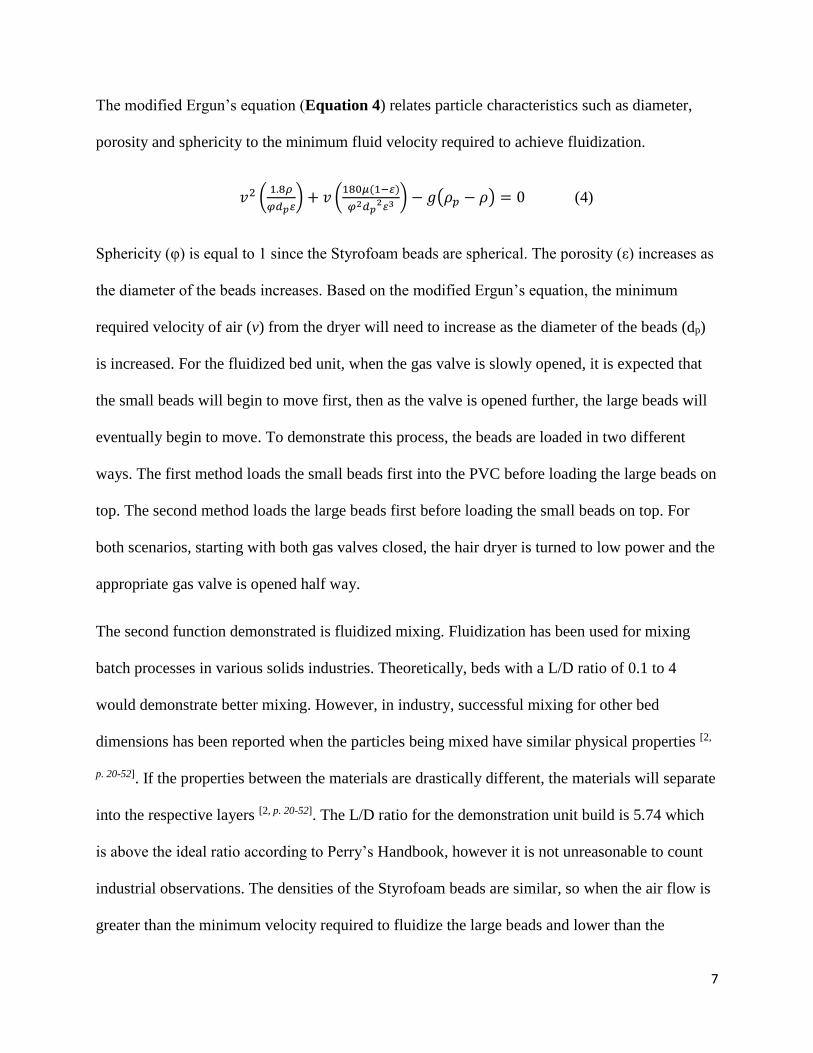
The modified Ergun’s equation (Equation 4) relates particle characteristics such as diameter,
porosity and sphericity to the minimum fluid velocity required to achieve fluidization.
𝑣2 (1.8𝜌
𝜑𝑑𝑝𝜀) + 𝑣 (
180𝜇(1−𝜀)
𝜑2𝑑𝑝2𝜀3
) − 𝑔(𝜌𝑝 − 𝜌) = 0 (4)
Sphericity (φ) is equal to 1 since the Styrofoam beads are spherical. The porosity (ε) increases as
the diameter of the beads increases. Based on the modified Ergun’s equation, the minimum
required velocity of air (v) from the dryer will need to increase as the diameter of the beads (dp)
is increased. For the fluidized bed unit, when the gas valve is slowly opened, it is expected that
the small beads will begin to move first, then as the valve is opened further, the large beads will
eventually begin to move. To demonstrate this process, the beads are loaded in two different
ways. The first method loads the small beads first into the PVC before loading the large beads on
top. The second method loads the large beads first before loading the small beads on top. For
both scenarios, starting with both gas valves closed, the hair dryer is turned to low power and the
appropriate gas valve is opened half way.
The second function demonstrated is fluidized mixing. Fluidization has been used for mixing
batch processes in various solids industries. Theoretically, beds with a L/D ratio of 0.1 to 4
would demonstrate better mixing. However, in industry, successful mixing for other bed
dimensions has been reported when the particles being mixed have similar physical properties [2,
p. 20-52]. If the properties between the materials are drastically different, the materials will separate
into the respective layers [2, p. 20-52]. The L/D ratio for the demonstration unit build is 5.74 which
is above the ideal ratio according to Perry’s Handbook, however it is not unreasonable to count
industrial observations. The densities of the Styrofoam beads are similar, so when the air flow is
greater than the minimum velocity required to fluidize the large beads and lower than the

8
minimum elutriation velocity, the beads are expected to distribute and mix together. The hair
dryer is turned to low power and the gas valve is opened almost all the way.
The third function demonstrated is elutriation where the resulting air flow is greater than the
terminal velocity of the beads. The gas valve is full open with the hair dryer set to low power. It
is expected that when the valve is fully opened, the beads will expand higher than the length of
the PVC tube. The additional large diameter catching section on top of the PVC pipe will cause
the particles to fall back into the pipe without spilling over and onto the floor.
Results
When the small beads are loaded first and the valve is opened half-way, the small beads on top
fluidize and expand while the large beads remain stationary. When the valve is opened almost all
the way, the large beads begin to move. Figures 4 a-d depict stills of the two layers fluidizing at
different valve positions. As the valve is opened further, the small beads fluidize first then the
large beads do not fluidize until after the air flow rate has increased.
A) B)

9
C) D)
Figure 4a-d: Pictures taken at varying air flows starting with a closed valve to an almost open
valve. A) Valve is closed, no movement takes place. B) Valve is half open, the small beads are
fluidized and the large remain still. C) Valve is ¾ open, the small beads are expanding and there
is slight movement in the large beads. D) Valve is about 90% open, both layers are fluidized.
When the large beads are loaded first and the valve is opened half-way (Figures 5a-d), the small
beads begin to fluidize and expand, while the large beads sit still. There is enough force to push
the entire large beads section up the entirety of the bed. Once the beads reached the top of the
bed, they popped into the catching section before falling back into the bed.

10
A) B)
C) D)
Figure 5 a-d: Pictures taken at varying air flows starting with a closed valve to a half open
valve. A) Valve is closed, no movement is observed. B) Valve is ¼ open, the small beads begin
to fluidize and push the large beads up the column. C) Large beads have been pushed further up
the column. D) Valve is half open, the large beads have popped into the catching section.
11
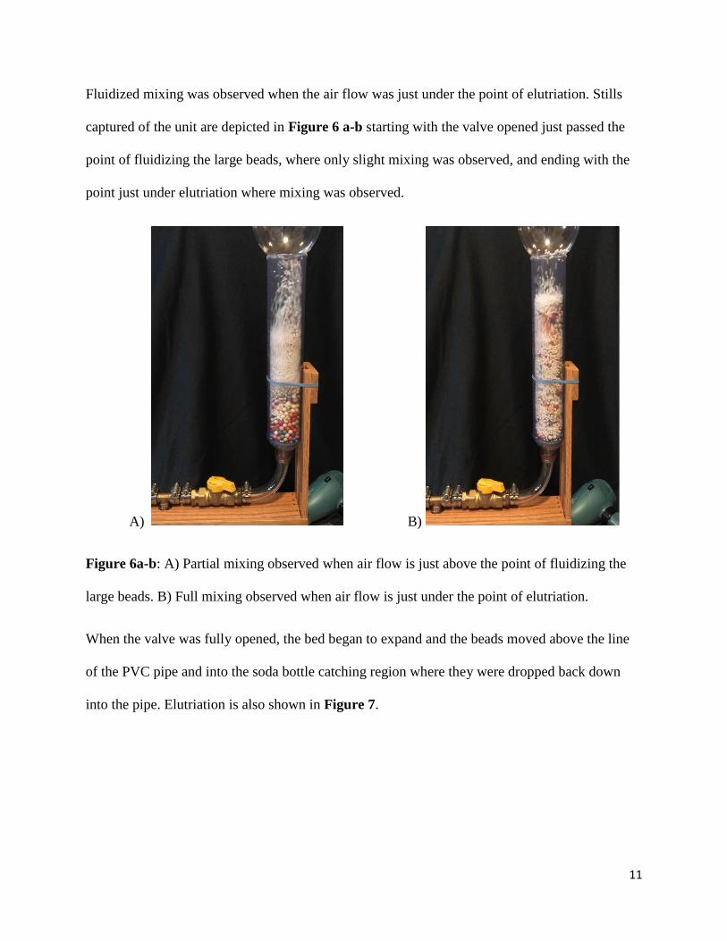
Fluidized mixing was observed when the air flow was just under the point of elutriation. Stills
captured of the unit are depicted in Figure 6 a-b starting with the valve opened just passed the
point of fluidizing the large beads, where only slight mixing was observed, and ending with the
point just under elutriation where mixing was observed.
A) B)
Figure 6a-b: A) Partial mixing observed when air flow is just above the point of fluidizing the
large beads. B) Full mixing observed when air flow is just under the point of elutriation.
When the valve was fully opened, the bed began to expand and the beads moved above the line
of the PVC pipe and into the soda bottle catching region where they were dropped back down
into the pipe. Elutriation is also shown in Figure 7.

12
Figure 7: Elutriation when the valve is fully open.
Safety Information
Using a hairdryer as the air source presents one hazard that must be kept in mind when operating
the unit. The heating element could not be removed or bypassed in order to run the dryer on cold
at all times. Removing the heating coil would eliminate a resistive element in the circuitry and
disassembling the hairdryer would have resulted in breaking the outer casing. Therefore, the cold
button on the dryer must always be pressed either by holding the dryer to push the button or by
taping the button down tightly. There is enough pressure buildup in the unit that if the cold
button is not pushed at all times, the hairdryer will over heat and automatically switch off. The
overheating issue is also why the dryer needs to be run at low power. When running at high
power, the dryer heats up much quicker even with the cold button pushed. The hair dryer will no
longer operate until it is cooled off and reset. The heat from the dryer could also heat up the brass
male adapter at the hose connecting the dryer to the unit. This adapter may be warm to the touch.

13
Economics
To keep the cost of the unit low, the source of air flow was a standard variable speed hair dryer
obtained from a local store. No modifications could be made to the dryer to eliminate the heating
element, as the coil acts as a resistive element in the circuit. Cutting the element would result in
the dryer not to be functional. The total cost of the components used in fabricating the unit is
$152.10 and does not include materials used to construct a functional prototype. Table 1 below
breaks down the cost of each element used to build the final unit. The oak wood and hardware
used to build the frame was donated by Bruce Chapa from the scrap wood pile from another
project. The materials used to build the functional prototype were collected from around the
house as to eliminate any financial cost but allow for testing of proof of concept.
Table 1: Pricing information for each component used to build the fluidized bed demonstration
unit.
Item Cost
5/8" ID tubing 10ft 22.03$
#2 Pipe 2 ft 34.82$
Hose Clamps 8.84$
Air Filter 5.79$
Gas Valves x2 25.96$
3-way splitter 3.47$
Male adapters 6 pack 13.90$
Duct Tape 3.98$
Clear Spray Paint 4.48$
Clear Weld Epoxy 4.38$
Soda Bottles x2 2.75$
Hair Dryer 15.12$
Styrofoam Beads Pack 6.58$
Oak Wood -$
Total Cost 152.10$

14
Conclusions and Recommendations
Based on the results of the testing, the unit demonstrated three main functions of a fluidized bed.
The first was the increased air flow velocity required for the larger diameter beads than the
smaller diameter beads. The second was the concept of fluidized mixing where at a fluid velocity
just under elutriation yielded a mixed system since the physical properties of the different sized
beads are very similar. The third was elutriation which was demonstrated with the valve in the
full open position and the dryer at low power. Each concept was demonstrated successfully while
conforming to the design constraints set at the beginning of the project. The unit is portable,
weighing 5.8 lbs with a height of 2ft 6.5 in and a length of 1ft 8.75in, which is capable of being
carried to a classroom across campus. The wooden frame is sturdy and allows the unit to be free
standing. All materials, excluding the piping and Styrofoam beads, were purchased at a hardware
or department store. The final project cost is $152.10. While no set budget was put in place, this
unit could be considered inexpensive.
Further design changes could be made around the air source to allow the unit to handle materials
denser than Styrofoam. The pressure buildup at high power and denser materials caused the hair
dryer to heat up quickly and did not allow for the aforementioned tests to be performed. An
alternative source of air that does not have a heating coil limitation is recommended.
Additionally, static was a large variable when using the Styrofoam beads with the PVC piping.
While the clear coat of spray paint and static guard worked to eliminate the static, the beads and
inside of the tube had to be sprayed if the unit had been sitting for more than a few days. Another
material that would not be affected by static buildup in the PVC pipe would also be
recommended.

15
Acknowledgements
I would like to thank my father, Bruce Chapa, for allowing me to use his woodworking shop and
donating materials to build the frame for the unit. I would also like to thank Dr. George Chase
for sponsoring this project. I enjoyed the independent designing and building in this final project
that could be used as an instructional tool for students in the years to come. Finally, I would like
to thank the Department of Chemical and Biochemical Engineering at the University of Akron
for which this unit is donated to and the William’s Honors College for this experience at the
conclusion of my undergraduate career.
References
[1] McCabe, W. L., Smith, J. C., & Harriott, P. (2005). Unit operations of chemical engineering
(7th ed.). Boston: McGraw-Hill Education (India) Private Limited.
[2] Perry, J. H. (1963). Chemical Engineering Handbook (4th ed.). p. 20-52. New York:
McGraw-Hill.
[3] Rober, M. (2017, November 28). Liquid Sand Tub. Retrieved from
https://www.markroberbuildinstructions.com/liquid-sand-tub

16
Appendix
Figure A1: Dimensioned drawing for the functional portion of the fluidized bed demonstration
unit. Not to scale.
Table A1: Summary of all parts purchased to build the fluidized bed unit with their associated
part numbers and source. Only the parts from Amazon and McMaster Carr were ordered online
and have a shipping cost included in the price. All other parts were purchased in person.

17
A) B)
Item Part # Source Cost
5/8" ID tubing 10ft 5233K69 McMaster Carr 22.03$
#2 Pipe 2 ft 49035K48 McMaster Carr 34.82$
Hose Clamps 47785 Lowe's 8.84$
Air Filter 552965 Lowe's 5.79$
Gas Valves x2 867990 Lowe's 25.96$
3-way splitter 818287 Lowe's 3.47$
Male adapters 6 pack 818276 Lowe's 13.90$
Duct Tape 488070 Lowe's 3.98$
Clear Spray Paint 20066387587 Home Depot 4.48$
Clear Weld Epoxy 43425501141 Home Depot 4.38$
Soda Bottles x2 ACME (grocery) 2.75$
Hair Dryer 1042000314 Walmart 15.12$
Styrofoam Beads Pack B073D29TSG Amazon 6.58$
Oak Wood My House -$
152.10$ Total Cost
Air
Filter

18
C) D)
E)

19
Figure A2a-e: Additional pictures of the fluidized bed demonstration unit. A) The entire
apparatus. B) The blue air filter is attached inside the PVC pipe and soda bottle adapter. The
Styrofoam beads are not able to fall down into the piping and the air is able to flow upward. C)
The underside of the wood base where the dryer connection is made at the splitter. D) A top view
of the valves, piping connectors and hose clamps. E) The retractable chord and collapsible hair
dryer connection to the unit. The cold button is taped down with electrical tape.