Fluid System 11-Axial Flow Compressor and Fan
29
Dr. Ir. Harinaldi, M.Eng Mechanical Engineering Department Faculty of Engineering University of Indonesia Axial flow compressor and fans
-
Upload
dieter-rahmadiawan -
Category
Documents
-
view
28 -
download
4
description
Axial Compresor
Transcript of Fluid System 11-Axial Flow Compressor and Fan
Dr. Ir. Harinaldi, M.EngMechanical Engineering Department
Faculty of Engineering University of Indonesia
Axial flow compressor and fans
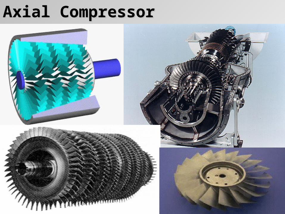
Axial CompressorAxial Compressor
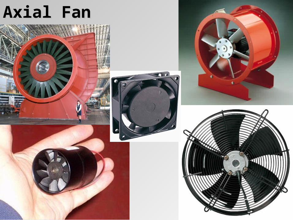
Axial FanAxial Fan
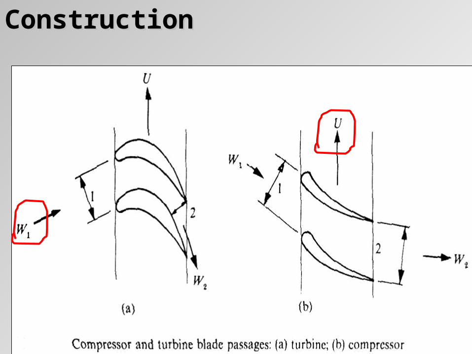
ConstructionConstruction
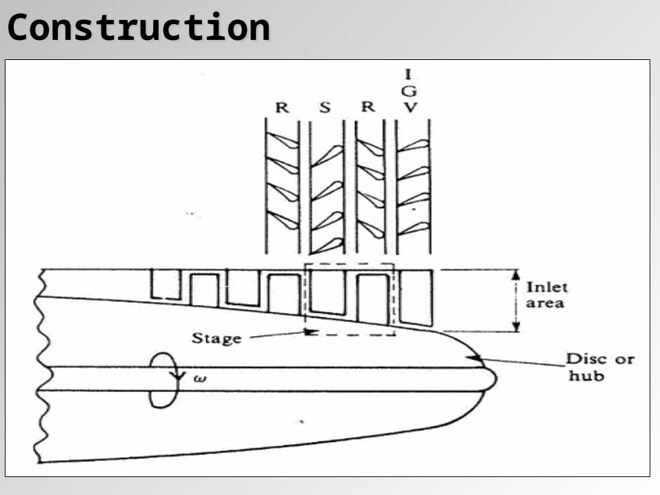
ConstructionConstruction
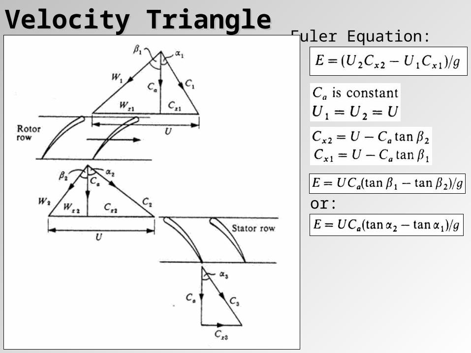
Velocity TriangleVelocity TriangleEuler Equation:
or:
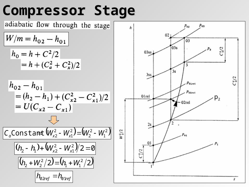
Compressor StageCompressor Stage
0221
2212 xx WWhh
22 211
222 WhWh
21
22
21
22Constant WWWWC xxa
refref hh 0102
p2
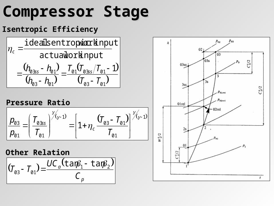
Compressor StageCompressor StageIsentropic Efficiency
0103
010301
0103
0103 1
input work actual
input work isentropic ideal
TT
TTT
hh
hh ssss
c
Pressure Ratio
1
01
01031
01
03
01
03 1
T
TT
T
T
p
pc
ss
Other Relation
p
a
C
UCTT 21
0103
tantan
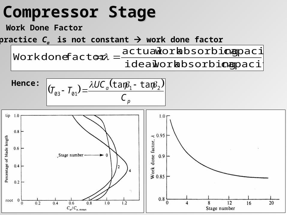
Compressor StageCompressor StageWork Done Factor
capacity absorbing work ideal
capacity absorbing work actualfactor doneWork
In practice Ca is not constant work done factor
p
a
C
UCTT 21
0103
tantan
Hence:
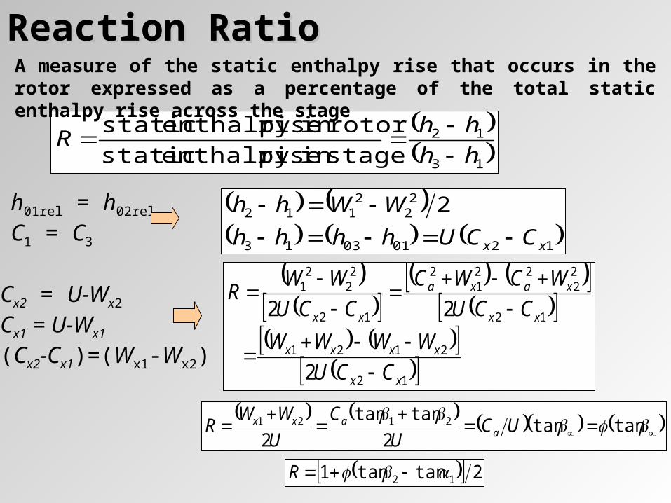
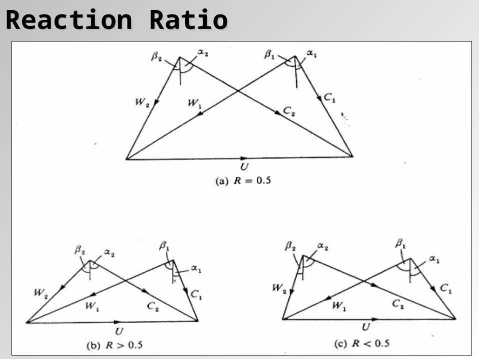
Reaction RatioReaction Ratio
13
12
stagein riseenthalpy static
rotorin riseenthalpy static
hh
hhR
A measure of the static enthalpy rise that occurs in the rotor expressed as a percentage of the total static enthalpy rise across the stage
12010313
22
2112 2
xx CCUhhhh
WWhh
h01rel = h02rel
C1 = C3
12
2121
12
22
221
2
12
22
21
2
22
xx
xxxx
xx
xaxa
xx
CCU
WWWW
CCU
WCWC
CCU
WWR
Cx2 = U-Wx2
Cx1 = U-Wx1
(Cx2-Cx1)=(Wx1-Wx2)
tantan
2
tantan
22121 UC
U
C
U
WWR a
axx
2tantan1 12 R
Reaction RatioReaction Ratio
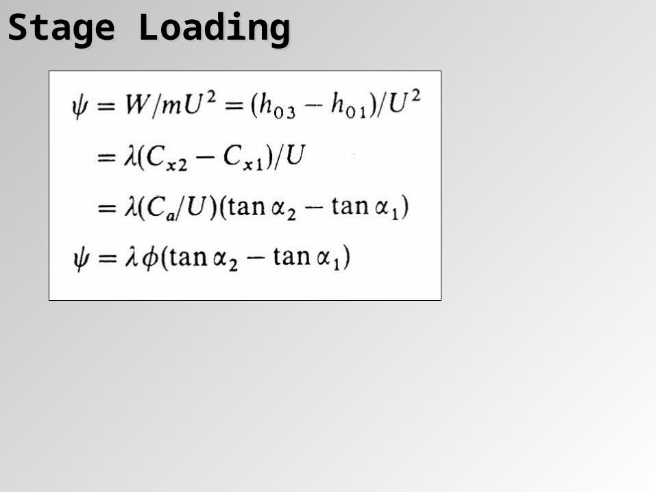
Stage LoadingStage Loading
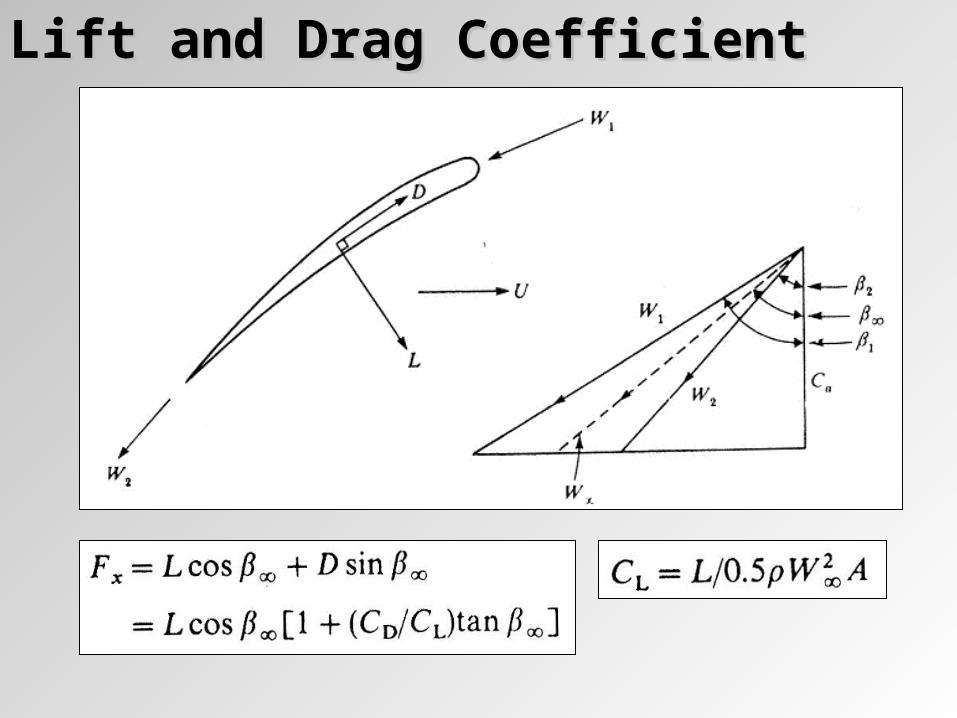
Lift and Drag CoefficientLift and Drag Coefficient
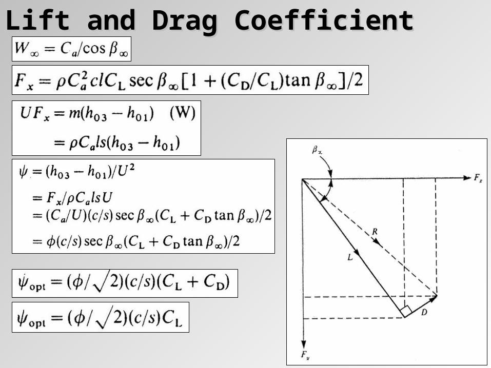
Lift and Drag CoefficientLift and Drag Coefficient
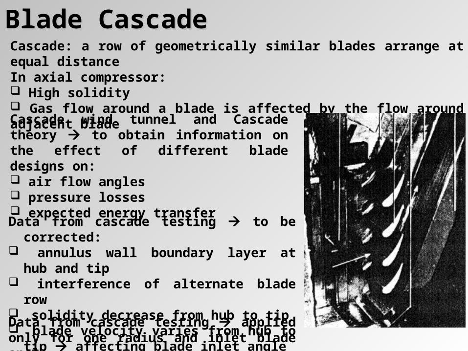
Blade CascadeBlade CascadeCascade: a row of geometrically similar blades arrange at equal distanceIn axial compressor: High solidity Gas flow around a blade is affected by the flow around adjacent blade
Cascade wind tunnel and Cascade theory to obtain information on the effect of different blade designs on: air flow angles pressure losses expected energy transfer
Data from cascade testing to be corrected: annulus wall boundary layer at hub and tip interference of alternate blade row solidity decrease from hub to tip blade velocity varies from hub to tip
affecting blade inlet angle
Data from cascade testing applied only for one radius and inlet blade angle
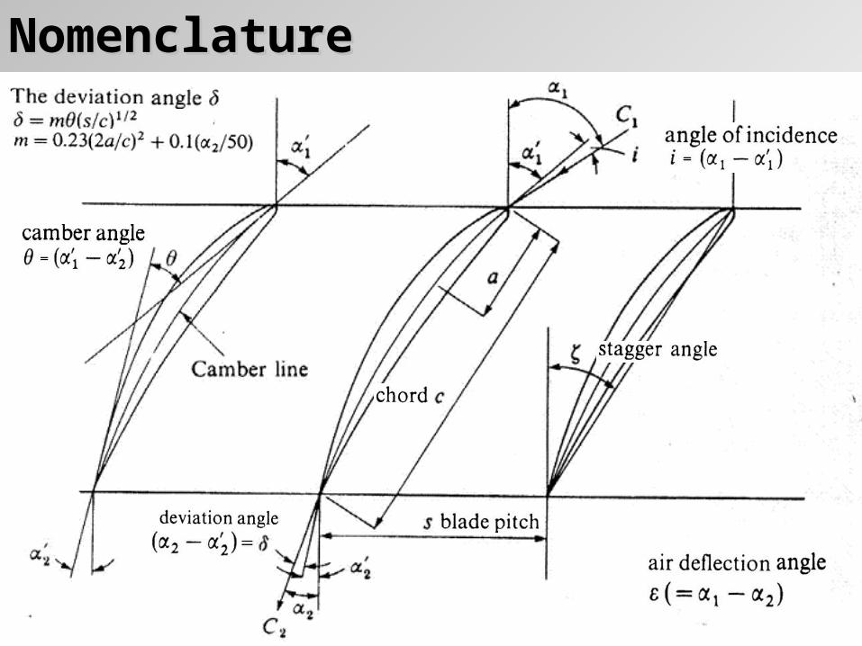
NomenclatureNomenclature
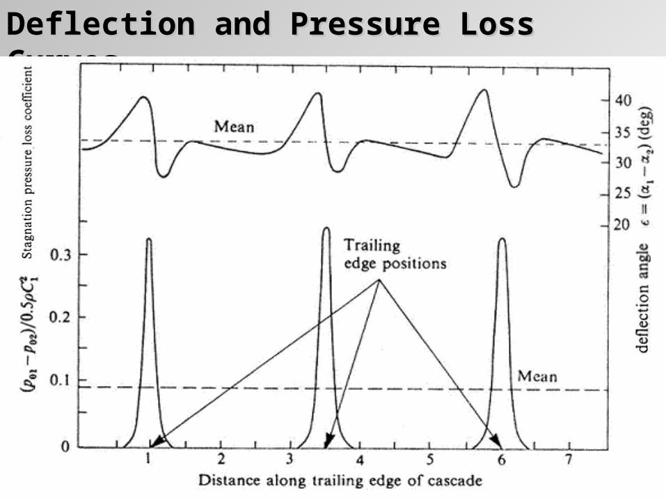
Deflection and Pressure Loss CurvesDeflection and Pressure Loss Curves
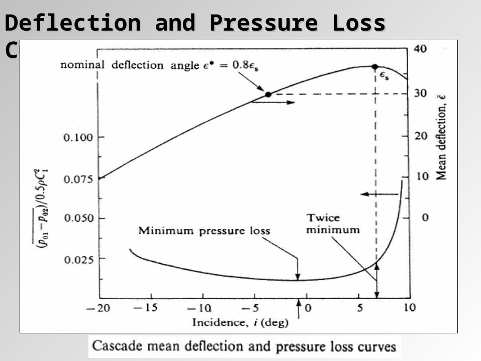
Deflection and Pressure Loss CurvesDeflection and Pressure Loss Curves
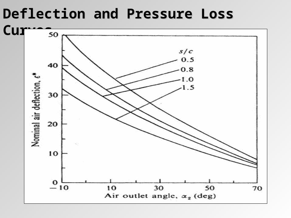
Deflection and Pressure Loss CurvesDeflection and Pressure Loss Curves
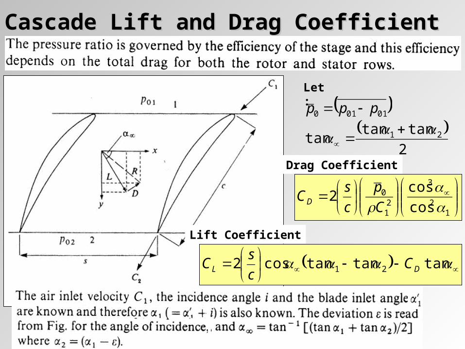
Cascade Lift and Drag CoefficientCascade Lift and Drag Coefficient
12
3
21
0
cos
cos2
C
p
c
sCD
Drag Coefficient
Lift Coefficient
tantantancos2 21 DL C
c
sC
01010 ppp
2
tantantan 21
Let:
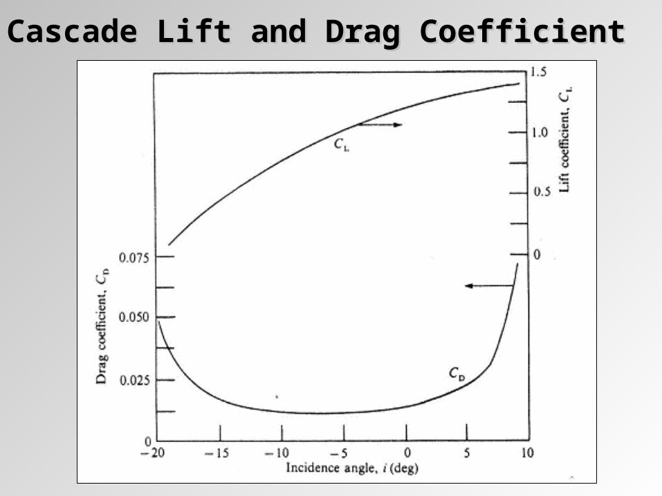
Cascade Lift and Drag CoefficientCascade Lift and Drag Coefficient
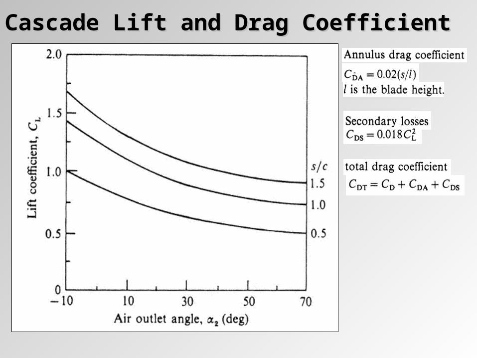
Cascade Lift and Drag CoefficientCascade Lift and Drag Coefficient
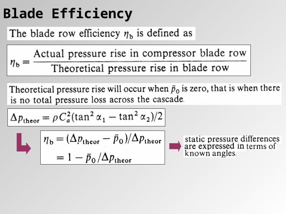
Blade EfficiencyBlade Efficiency
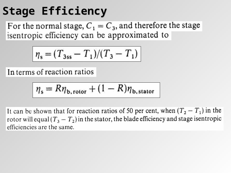
Stage EfficiencyStage Efficiency
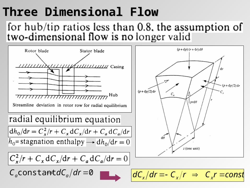
Three Dimensional FlowThree Dimensional Flow
0constant drdCC aa constrCrCdrdC xxx
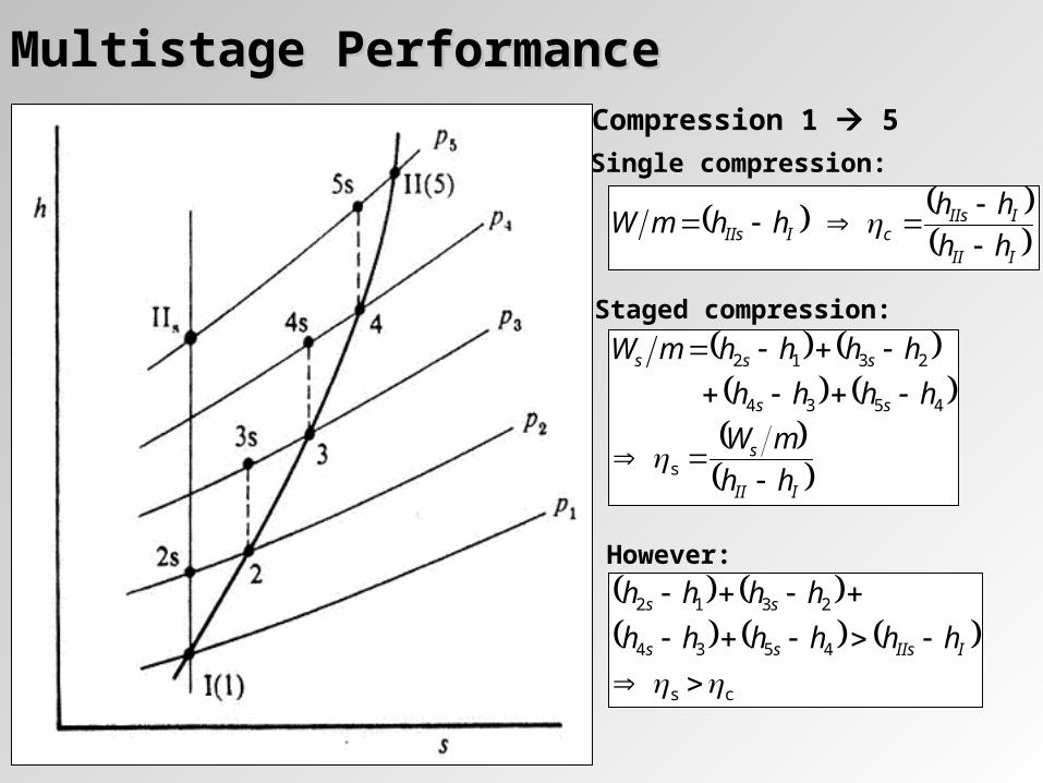
Multistage PerformanceMultistage PerformanceCompression 1 5
Single compression:
III
IIIscIIIs hh
hhhhmW
Staged compression:
III
s
ss
sss
hh
mW
hhhh
hhhhmW
s
4534
2312
cs
4534
2312
IIIsss
ss
hhhhhh
hhhhHowever:
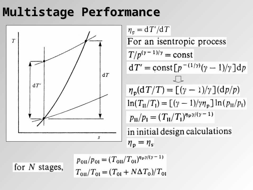
Multistage PerformanceMultistage Performance
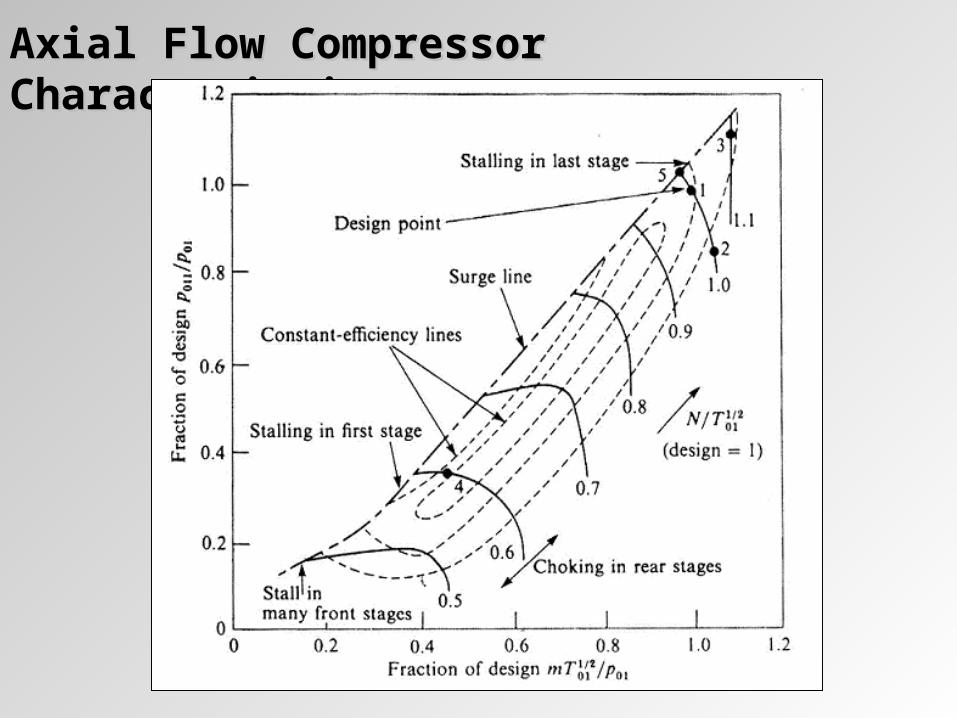
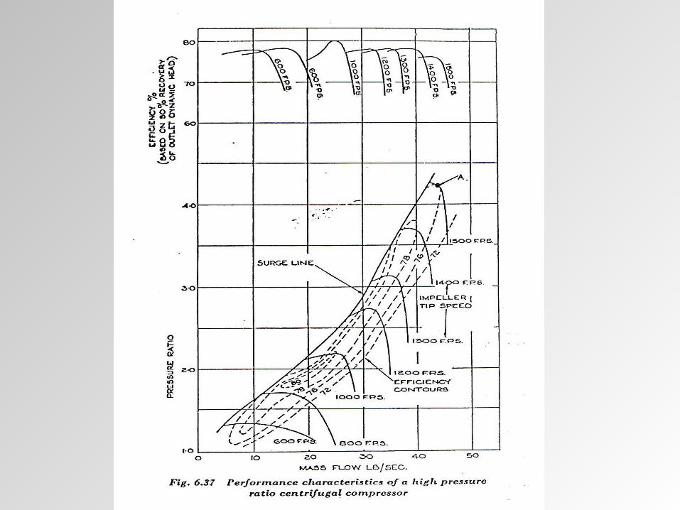
Axial Flow Compressor CharacteristicsAxial Flow Compressor Characteristics