Fluid-structure interaction in liquid-filled pipe systems...
56
Rapport IWDE 02 - 05 Fluid-structure interaction in liquid-filled pipe systems: sources, solutions and unsolved problems A.S. Tijsseling Mei2002 Instituut Wiskundige Dienstverlening Eindhoven Technische Universiteit Eindhoven
Transcript of Fluid-structure interaction in liquid-filled pipe systems...

Rapport IWDE 02 - 05
Fluid-structure interaction in liquid-filled pipe systems: sources, solutions and unsolved problems
A.S. Tijsseling
Mei2002
Instituut Wiskundige Dienstverlening Eindhoven
Technische Universiteit Eindhoven

FLUID-STRUCTURE INTERACTION IN LIQUID-FILLED PIPE SYSTEMS:
SOURCES, SOLUTIONS AND UNSOLVED PROBLEMS
A.S. Tijsseling
May2002
EDF Final Report
T u I e technisc:he universiteit eindhoven

FLUID-STRUCTURE INTERACTION IN LIQUID-FILLED PIPE SYSTEMS:
Resume
SOURCES, SOLUTIONS AND UNSOLVED PROBLEMS
A.S. Tijsseling Department of Mathematics and Computer Science
Eindhoven University of Technology P.O. Box 513, 5600MB Eindhoven
The Netherlands
May2002
Research Report
Final Report for:
ELEC1RICITE DE FRANCE
Direction des Etudes et Recherches Service Ensembles de Production
Departement Acoustique et Mecanique Vibratoire 1 avenue du General de Gaulle
92141 Clamart France
Contract Number: E26991
Research Officers: Patrick Vaugrante, Pierre Moussou and Sebastien Caillaud
This final report is the result of an extensive literature and internet search. It is intended as an introduction to the subject and as a guide to relevant literature.
The main themes are FSI (fluid-structure interaction) and FIV (flow-induced vibration) in
liquid-filled pipe systems. Roughly, one may say that FSI refers to unsteady and FIV to steady flow
phenomena, exciting pipe systems. The review is specially dedicated to ED F. The report lists 146 references.

SUMMARY
The themes of this report are fluid-structure interaction (FSI) and flow-induced vibration (FIV) in
internal liquid flows (as opposed to external and gas flows) in pipe systems. Roughly one may say
that PSI stands for unsteady-flow induced vibration and FIV for steady-flow induced vibration.
This is explained in Section 2.
The report is a survey of and a guide to literature on PSI and FIV. For PSI, the review by
Wiggert and Tijsseling (2001) is the starting point. Section 3 summarises the subject and lists new
references. For FIV, the review by Weaver et al (2000) is the starting point. Section 4 summarises
this paper and also the standard textbooks. A list of all possible excitation sources can be found in
Section 5. Vibrating bends and branches, being the most important PSI mechanisms, are studied in
Section 6. The Sections 7 and 8 are on codes, standards and current research activity. Future work
and conclusions are given in the Sections 9 and 10. The list of references comprises 146
publications.

TABLE OF CONTENTS
SUMMARY
1. PERSONALBACKGROUND
1.1. The author
1.2. The institute
2. IN1RODUCTION
2.1. Context of the study
2.2. FSI versus FIV
2.3. Report outline
3. FLUID-STRUCTURE INTERACTION (FSn
3 .1. History
3.2. Coupling mechanisms
3.3. Importance of FSI
3.4. Practical applications
3.5. Recent work
4. FLow-INDUCED VmRATION (FIV)
4.1. Introduction
4.2. Review paper by Weaver et al (2000)
4.2.1. Turbulence
4.2.2. Vorticity shedding
4.2.3. Leakage flow-induced vibration
4.2.4. Axial-flow-induced vibration
4.2.5. Fluidelastic instability
4.3. The textbooks
5. EXCITATION SOURCES: SUMMARY
5.1. Exciters for the fluid
5.2. Exciters for the piping
6. EXCITATION SOURCES: VffiRATING BENDS AND BRANCHES
6.1. Introduction
6.2. Bends
6.3. Branches
1
1
1
2
2
2
3
4
4
5
7
12
13
14
14
14
14
15
16
17
17
18
23
23
26
26
26
27
29

7. CODES AND STANDARDS
7.1. ASMEB31
7 .2. NEN 3650
7.3. Stress criteria
8. CURRENT PSI RESEARCH ACTIVITY
9. UNSOLVED PROBLEMS
1 O.CONCLUSION
ACKNOWLEDGEMENTS
REFERENCES
History
PSI - reviews
PSI- recent work (1997-2002)
PSI - earlier work (before 1997)
PSI - single-elbow experiments and single-branch experiments
PIV - reviews
PIV - textbooks
PIV - papers and reports
Codes and Standards
Stress criteria
ACRONYMS
SYMBOLS
29
30
30
30
30
32
33
34
34
34
35
36
39
40
42
43
45
47
47
48
48

1
1. PERSONALBACKGROUND
1.1. The author
Arris S Tijsseling has an MSc (in Technical Mathematics and Informatics) and a PhD (in
Civil Engineering) from Delft University of Technology in The Netherlands. He has spent two and
half years at the renowned Dutch research institutes National Aerospace Laboratory and
Delft Hydraulics Laboratory. He has been a post-doctoral research fellow with Professor
AlanE Vardy, working on the suppression of waterhammer-induced vibration, in the Department
of Civil Engineering of the University of Dundee, Scotland. On 1 December 1995 he was
appointed Lecturer in the field of Fluid Mechanics. Per 1 September 1999 he is Assistant Professor
in the Department of Mathematics and Computer Science of Eindhoven University of Technology.
The author has been working on fluid-structure interaction (FSI) in pipe systems since 1986 and
has about 35 publications on this subject. In 1994 he was co-recipient of the Vreedenburgh prize of
the Royal Dutch Institute of Engineers. The applicant's work is referenced in the Dutch Pipe Code
NEN-3650 English (1998). He is co-author ofEDF-DRD Technical Note HP-54/99/030/A (1999).
1.2. The institute
Eindhoven University of Technology (TUE) and
Eindhoven Centre for Computational Engineering (ECCE)
TUE-ECCE
TUE is a relatively young university. It was founded some 45 years ago and it is situated in the
southern part of The Netherlands. ECCE is a co-operation of some 15 chairs at TUE, from the
Departments of Mathematics and Computer Science, Technical Physics, Mechanical, Chemical
and Electrical Engineering. Industrial orientation, and at the same time a recognised high quality of
research, is evidenced by the establishment of top technological institutes (TTis) and top scientific
research schools in selected areas with a strong international profile. Indeed, one out of four
technological institutes and two out of five selected top research schools in The Netherlands have
their main base in Eindhoven.
Research
Theoretical and experimental science are more and more supplemented by computational science.
Modelling and numerical simulation are therefore an important tool. Typical areas in which
various groups work together are material technology, biomedical technology, process industry,
dynamics and control, heat and mass transfer and geophysical flows. Multidisciplinary teams work
here together with industrial companies on both small problems and longer-term basic issues.

2
Training ECCE fosters a training programme in Computational Science and Engineering (CSE). The
master's programme has a strong application orientation. Students are expected to take a minor in a
technical discipline and to carry out a practical 9 months project in an industrial environment. The
PhD programme is usually based on a problem originating from and often paid by industry. Also in
the framework of ECMI there is a European graduate programme.
Service
There exists strong co-operation with a large variety of industries. Smaller and larger projects for
companies are done by students, who often find a job there after completing their thesis. The
mathematics department has a special service bureau (IWDE) for technical co-ordination of such
contract work. There is expertise in doing this on an international level.
2. INTRODUCTION
2.1. Context of the study
Vibration in piping systems is a complex phenomenon not well understood by many pipework
designers. Currently there are no standards and just a few guidelines to assist in determining which
systems might be at risk. Through the project VICI, EDF is trying to improve its comprehension of
vibrations of water pipes in the low frequency range and to propose an approachable method of
analysis for the majority of the EDF piping systems (Moussou 2002).
This contract with Eindhoven University of Technology intends to fulfil a part of this objective
by summarising, from an engineering point of view, the mechanisms inducing vibrations in pipe
systems.
This report intends to be a guide to published work (papers and books) in the area of FSI (fluid
structure interaction) and FIV (flow-induced vibration) in liquid-filled pipe systems. This is a very
broad area, and only certain aspects of importance for EDF will be highlighted. The report should
leave the reader with an impression of what exists and of what still has to be developed.
Furthermore, codes and standards used in practice will be compared with the present state of
knowledge. An inventory of current research activities is presented.
2.2. FSI versus FIV
The terms FSI and FIV are used promiscuously in the literature. In this report, the term FSI is used
for unsteady flow interacting with pipe vibration. The term FIV will be used for stationary flow
inducing pipe vibration. FSI generally involves two-way (fluid H pipe) interaction. For FIV the

3 interaction normally is one-way (fluid~ pipe). Of course, there are regions where the above-made
definitions of FSI and FIV overlap.
The stationary (or steady) flow is considered time-averaged: it includes turbulence and vorticity,
and the associated small (compared to the steady state) velocity and pressure fluctuations. In this
sense, the above-made definitions differ from the classification made by Blevins ( 1990, p. 2) which
is shown in Figure 1. The top diagram refers to FIV and the bottom diagram to FSI, except that
herein the random excitation by turbulence is placed under the FIV label.
The terms waterharnmer and acoustics will be used in the following way, noting that both
phenomena concern pressure waves. Waterhammer is transient unsteady flow of large amplitude,
considered in the time domain. It is related to FSI. Acoustics concerns steady-oscillatory flow of
small amplitude, which may become of large amplitude under resonance and instability conditions.
It is considered in the frequency domain and related to both FSI and FIV. Waterharnmer can be
generated by valve and pump operation. Acoustic sources can be vortex shedding and the vibration
of fluid machinery. Of course, there are many grey areas where both definitions apply.
RANI.JOM SEAS iNDUCED
PUMP PULSATIIlN
FIGURE 1 (Blevins 1990, p. 2)
2.3. Report outline
SURGE
FSI and FIV are dealt with in the Sections 3 and 4, respectively. All possible sources of excitation
of liquid-filled pipe systems are summarised in Section 5. The most important of these probably is
the vibrating bend, which therefore deserves special attention in Section 6. What codes and
standards say about FSI and FIV is reported in Section 7. Section 8 surveys current research
activity and Section 9 addresses future work. Section 10 concludes the report.
4
3. FLUID-STRUCTURE INTERACTION (FSI)
The papers by Tijsseling (1996) and Wiggert and Tijsseling (2001) give a fairly complete picture
of what has been achieved in the area of fluid-structure interaction in liquid-filled pipe systems. A
short summary and some additions are given here. Section 3.5 lists overlooked and new
contributions to the subject that were not mentioned in the above-mentioned papers.
3.1. History
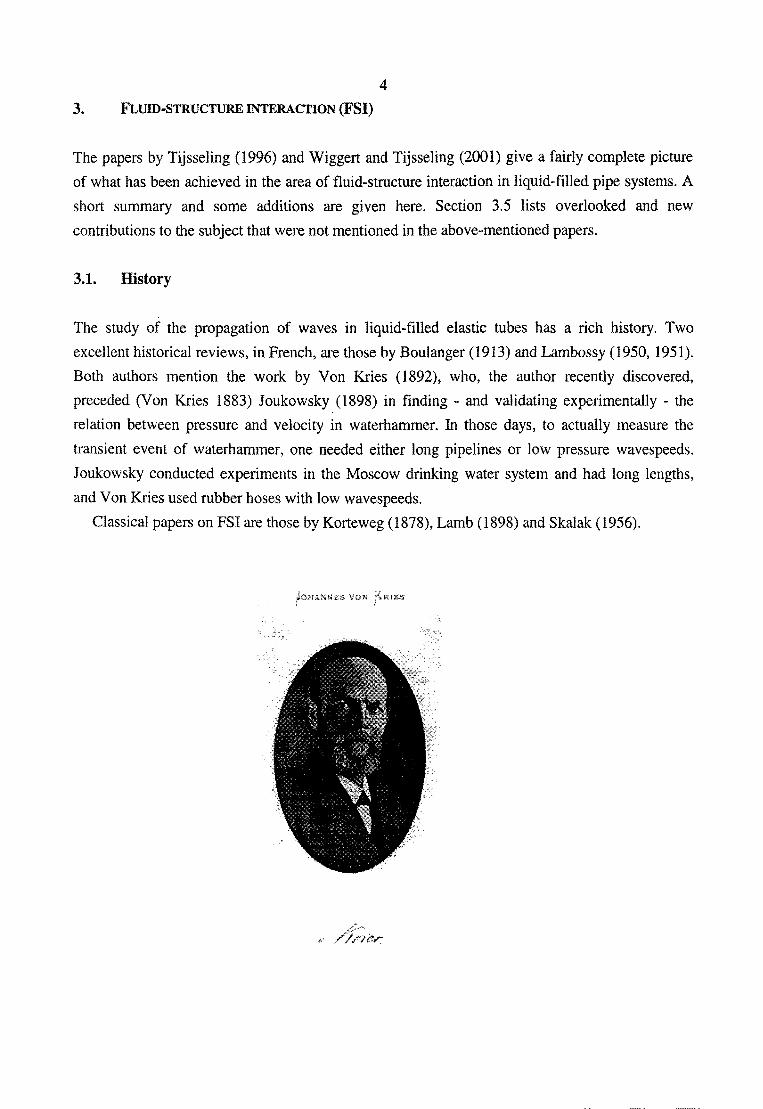
The study of the propagation of waves in liquid-filled elastic tubes has a rich history. Two
excellent historical reviews, in French, are those by Boulanger (1913) and Lambossy (1950, 1951).
Both authors mention the work by Von Kries (1892), who, the author recently discovered,
preceded (Von Kries 1883) Joukowsky (1898) in finding - and validating experimentally - the
relation between pressure and velocity in waterhammer. In those days, to actually measure the
transient event of waterhammer, one needed either long pipelines or low pressure wavespeeds.
Joukowsky conducted experiments in the Moscow drinking water system and had long lengths,
and Von Kries used rubber hoses with low wavespeeds.
Classical papers on FSI are those by Korteweg (1878), Lamb (1898) and Skalak (1956).
VON
5
3.2. Coupling mechanisms
PSI in liquid-filled pipe systems is caused by four interaction mechanisms: friction coupling,
Poisson coupling, junction coupling and Bourdon coupling. Friction coupling is the mutual friction
between the liquid and the axially vibrating pipe wall. Poisson coupling relates pressures in the
liquid to axial stresses in the pipes through the radial displacements of the pipe walls. While
friction and Poisson coupling act along the entire pipe, the more important junction coupling acts
wherever there is a branch or a change in area or flow direction. For example, the vibration of a
short unrestrained elbow generates pressure variations in the liquid, which in turn excites the elbow
and other junctions in the system. Bourdon coupling occurs in curved fluid-filled tubes of (slightly)
non-circular cross-section. Internal fluid pressure unbends the tube and externally imposed bending
changes the fluid flow. The mechanism, used in Bourdon gauges to measure liquid pressures, is
probably best known from unrolling paper party tooters.
Dimensional or multi-scale analysis will show that friction (coupling) is unimportant in transient
events. The Poisson coupling terms generally are small, but their effect may accumulate in time.
Poisson coupling is of importance for modes of vibration that are predominantly in the axial
direction of the individual pipes. Junction coupling is important when the excitation is fast enough
to generate large unbalanced pressure forces in the piping system.
Pipe systems vibrate in axial, radial, lateral and torsional directions. In the axial vibration pipe and
fluid interact through Poisson and friction coupling. In the lateral vibration the contained liquid
acts as added mass. Torsional vibration is not affected by the liquid. Unrestrained pipe junctions
couple fluid and pipes, and they let the axial, lateral and torsional vibrations interact.
Chen (1987, Section 4.3) showed that two modes of axial wave propagation are non-evanescent at
low frequencies. One mode corresponds to pressure waves with large radial pipe expansions, the
other to axial stress waves with small radial pipe contractions. The two modes, corresponding to
waterhammer and precursor waves, are non-dispersive at low frequencies. The constant phase
velocities (wavespeeds) are defined by Chen's equation 4.15, which takes into account the
influence of wall thickness; i.e. terms of the order of e/R are not neglected with respect to 1.
Chen (1987, Section 4.3) showed that only one mode of lateral wave propagation exists at low
frequencies. This mode is highly dispersive. Chen followed Reissner (1955) in defining the
dispersion equation 4.19, which includes both the pipe wall thickness and a frequency-dependent
added mass coefficient. Figure 2, from (Chen 1987, Section 4.3, Fig. 4.5), shows that the added
mass coefficient, Cm, given in his equation 4.14, is close to one at low frequencies, a = 2nR/A.,
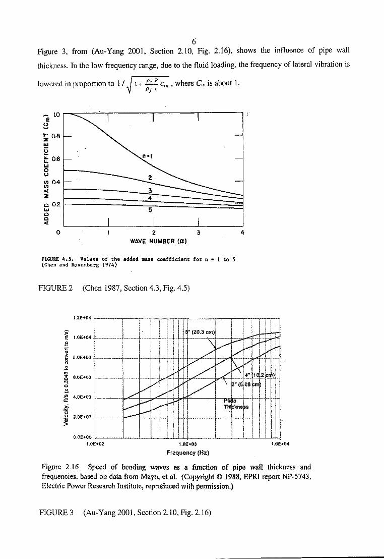
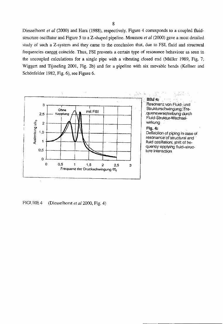
6 Figure 3, from (Au-Yang 2001, Section 2.10, Fig. 2.16), shows the influence of pipe wall
thickness. In the low frequency range, due to the fluid loading, the frequency of lateral vibration is
lowered in proportion to 1 I 1 + .P..J..J!.. Cm , where Cm is about 1. Pf e
.... 1.0 .--,.,.---..:..-,.-------.-----""'T""------, \. E
(,) ......
0 2 3 WAVE NUMBER (a)
FIGURE 4.5. Values of the added mass coefficient for n • 1 to 5 (Chen and Rosenberg 1974)
FIGURE 2 (Chen 1987, Section 4.3, Fig. 4.5)
.s <0 C!; 6JlE+03 ('7
d !!. ~ 4.01:+03
~ o 2.0E+03 ·1--~-~:::.......t-+--~f...-~
O.OE+OO ·J----....1.....-..S........-1--1-..I.-
1.0E.+02 1.0E+03
Frequency (Hz)
4
Ule+04
Figure 2.16 Speed of bending waves as a function of pipe wall thickness and frequencies, based on data from Mayo, et al. (Copyright C 1988, BPRI report NP-5743, Electric Power Research Institute1 reproduced with permission.)
FIGURE 3 (Au-Yang 2001, Section 2.10, Fig. 2.16)

7
3.3. Importance of FSI
The main effects of fluid-structure interaction are problem dependent. When compared to
predictions of conventional waterhammer and uncoupled analyses, predictions including fluid
structure interaction may lead to: higher or lower extreme pressures and stresses, changes in the
natural frequencies of the system, and more damping and dispersion in the pressure and stress
histories.
The classical theory of waterhammer predicts a square-wave pressure history (at the valve, friction
neglected) in a reservoir-pipeline-valve system subjected to sudden valve closure (Chaudhry 1987,
p. 14; Wylie and Streeter 1993, p. 50, p. 65). It has been shown by Tijsseling and Heinsbroek
(1999) that this square wave is distorted in flexibly supported pipelines. Moving pipe (b)ends may
( 1) introduce higher-frequency pressure oscillations, (2) make square waves "triangular" and
consequently wavefronts less steep, (3) change the system's main frequency and (4) invalidate
application of Joukowsky's formula (Eq. 1 herein).
Fully fluid-structure coupled models are required to analyse flexible pipelines subjected to rapid
excitation, in particular to assess accurately the anchor forces. FSI models give a more accurate
prediction of pressure, stress and displacement amplitudes, of natural and resonance frequencies, of
damping, and of anchor and support forces.
Amplitudes
Many investigators have shown that the pressure amplitudes during a waterhammer event in a
pipeline may exceed Joukowsky's value (Eq. 1 herein) as a result of pipe flexibility. For example,
figure 7c in (Tijsseling 1996) shows a Joukowsky overshoot of 100%. In general, the flexibility of
pipe systems causes pressures higher than Joukowsky in the beginning of a transient event. Later
on, in systems with movable bends, the pressures will be lower than Joukowsky, because energy
has then been transferred from the fluid pulsation to lateral pipe vibration.
Frequencies
The structural natural frequencies of a fluid-filled pipe system are usually obtained from an
analysis in which the fluid is dead mass. The fluid natural frequencies, if required, are then
obtained from an analysis in which the pipe system is rigid. This approach will fail in compliant
systems with structural and fluid frequencies close to each other. Fluid-structure interaction by
junction coupling - e.g. movable (b )ends - will separate coinciding fluid and structural frequencies
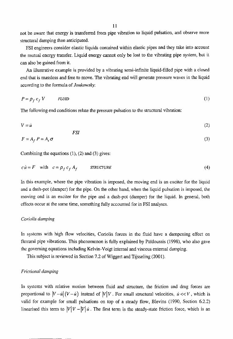
(as found without considering FSI). This is nicely shown in the Figures 4 and 5 copied from
8
Diesselhorst et al (2000) and Hara (1988), respectively. Figure 4 corresponds to a coupled fluid
structure oscillator and Figure 5 to a Z-shaped pipeline. Moussou et al (2000) gave a most detailed
study of such a Z-systern and they carne to the conclusion that, due to FSI, fluid and structural
frequencies cannot coincide. Thus, FSI prevents a certain type of resonance behaviour as seen in
the uncoupled calculations for a single pipe with a vibrating closed end (Muller 1989, Fig. 7;
Wiggert and Tijsseling 2001, Fig. 2b) and for a pipeline with six movable bends (Kellner and
Schonfelder 1982, Fig. 6), see Figure 6.
3 Ohne
2.5 Kopplung +-t'~-il---.---
0
~ 2 0) c::: ::;, 1.5 -"' c::: ~
1 ~
0,5
0 0 0,5 1 1,5 2 2,5
Frequenz der Druckschwingung fifo
FIGURE 4 (Diesselhorst et a/2000, Fig. 4)
.BiJd4: 'R~sonanzvon Fluid- und Strukturschwingung;•.Ere-·.quenzyerschieb~.;tng avrch Fluid-Struktur~W~chsaiwirkung Fig. 4~ DefleCtion of piping In case of resonance of'structuraf and · t!uid oscillation~ $hift offrequef'lriy ·applying fluid..,.;struclt!re interaction

9
.... (a}
to . ..----...._-...,........,,------. • • :m¥ .. o.~~ '
1o~--1:--.... -~2:--~3
{.bJ
{c)
1 0~---+1----~2----~3 "" (41
l .. ; . 11•4"' .J/11P• .\.H-"
~t:,~~
FJ'r.
Fig. 7 Comparison of the aelsmic accetitaUon responlU~ spectrum.between the deacJ..mass model ( o) and tile pre1su,..~iping· InteractiOn model ( • )-• • {a) 0.5594, (b) 0.9945. (q) 1.7$3, 'd)'2.225
' . "" I. -d... /t:?
FIGURE 5 (Hara 1988, Fig 7)

10
48J A (mm}
J ......... mit Ftuid-Struktur-We.chsetwirkung - ohne Fluid-Struktur-Wechselwirkun~Q;
32
16
0
-16
-32
0 100 200 300 liJJ
Bild 6: y·Auslenkung des ersten KrOmmers Fig. 6: y·Deflection of the first bend
FIGURE 6 (Kellner and Schonfelder 1982, Fig. 6)
BOO SOO t (m sl
FSI prevents this type of resonance behaviour, because it prohibits coinciding fluid and structural
frequencies. Uncoupled calculations predict resonance, where fully-coupled calculations do not. In
this way the results of uncoupled calculations are much too conservative.
Damping
This subject has been reviewed by Leslie and Tijsseling (1999). See also Blevins (1990, Chapter
8).
FSI damping (from Leslie and Tijsseling 1999)
Hydraulic engineers regard pipes as rigid containers resisting their liquid flow through wall
friction. However, in waterhammer analyses the hoop elasticity of pipes is taken into account to
reduce the pressure wave speed. Pipe motion and associated inertia effects are normally ignored. In
doing so, they may not be aware that energy is transferred from liquid pulsation to pipe vibration,
and observe more liquid damping than anticipated.
Structural engineers regard liquids as rigid columns pressurising their elastic pipes. However, in
vibration analyses the mass of liquids is taken into account to reduce the structural frequencies.
Liquid elasticity and associated waterhammer effects are normally ignored. In doing so, they may
11 not be aware that energy is transferred from pipe vibration to liquid pulsation, and observe more
structural damping than anticipated.
FSI engineers consider elastic liquids contained within elastic pipes and they take into account
the mutual energy transfer. Liquid energy cannot only be lost to the vibrating pipe system, but it
can also be gained from it.
An illustrative example is provided by a vibrating semi-infinite liquid-filled pipe with a closed
end that is massless and free to move. The vibrating end will generate pressure waves in the liquid
according to the formula of Joukowsky:
FLUID (1)
The following end conditions relate the pressure pulsation to the structural vibration:
V=u (2)
FSI (3)
Combining the equations (1), (2) and (3) gives:
c u F with c = p f c f A1 STRUCTURE (4)
In this example, where the pipe vibration is imposed, the moving end is an exciter for the liquid
and a dash-pot (damper) for the pipe. On the other hand, when the liquid pulsation is imposed, the
moving end is an exciter for the pipe and a dash-pot (damper) for the liquid. In general, both
effects occur at the same time, something fully accounted for in FSI analyses.
Coriolis damping
In systems with high flow velocities, Coriolis forces in the fluid have a dampening effect on
flexural pipe vibrations. This phenomenon is fully explained by Pai'doussis (1998), who also gave
the governing equations including Kelvin-Voigt internal and viscous external damping.
This subject is reviewed in Section 7.2 ofWiggert and Tijsseling (2001).
Frictional damping
In systems with relative motion between fluid and structure, the friction and drag forces are
proportional to IV -ul (V -u) instead of IVIV. For small structural velocities, u <<V, which is
valid for example for small pulsations on top of a steady flow, Blevins (1990, Section 6.2.2)
linearised this term to lVI V -lVI u . The first term is the steady-state friction force, which is an

12
external force for the structure. 1n a harmonic analysis, because of the V non-linearity, this term
gives rise to higher harmonics. The second term is a time-dependent damping force for the
structure, which may not be neglected because it is of importance for the dynamic response near
resonance conditions.
Often the damping force will not follow the ideal of the viscous damper (which is proportional
to it ). It is possible to define equivalent viscous damping as the viscous damping that expends the
same energy per cycle of vibration as the actual damping force. Blevins (1990, Section 8.1, Table
8.1) gives equivalent damping factors for Coulomb (friction), hysteretic (displacement dependent)
and velocity power-law damping models.
3.4. Practical applications
The practical applications I importance of FSI can be captured by the following keywords:
Nuclear industry (safety)
Chemical industry (environment)
Aerospace industry (light structures)
Marine industry (noise)
Hydropower stations (stability)
Petroleum industry (long pipelines)
Earthquake engineering (Japan)
Dyke crossings (The Netherlands)
Biomedical engineering (haemodynamics)
Laboratory experiments (accuracy)
Fatigue
COSTS

13 3.5. Recent work
The three review papers by Wiggert (1996), Tijsseling (1996), and Wiggert and Tijsseling (2001)
give a fairly complete overview of FSI research and application. There is no need to repeat what is
mentioned in these papers here. What is listed below can be regarded as an addition to and
extension of the above review papers through overlooked and new literature.
Reseachers not mentioned in the three FSI reviews
Altstadt et al (2000);
Chun and Yu (2000);
Formaggia et al (2001 );
Giot et al (2001);
Hansson and Sandberg (2001);
Kollmann et al (1998);
Kollmann and Swidersky (2000a);
Kollmann and Swidersky (2000b );
Liu and Ohashi (1988);
Reissner (1955);
Repp (1998);
Schumann (1979);
Shu et al (2001);
Stoessel et al (1988);
Thompson et al ( 1989);
Uspuras et al (2001);
Vatkova et al (1999);
Yamaguchi et al (1982);
Yamaguchi and Kondo (1989)
Reseachers mentioned in the three FSI reviews, except for the papers:
Bahrar et al (1998b ); this is the paper of Bahrar et al (1998a) with viscoelasticity included;
Bergant and Tijsseling (2001);
Chen and Rosenberg (1974);
Charley et al (1998);
Charley and Carta (2001);
Ichchou et al (1998);
Ichchou et al ( 1999);

Jiao et al (1999);
Moussou and Boyelle (1999);
Muller (1989);
Munjal and Thawani (1997);
Ohayon (1986);
Tijsseling and Vaugrante (2001);
Zhang et al (2000a);
Zhang et al (2000b)
4. FLOW-INDUCED VIBRATION (FIV)
4.1. Introduction
14
FIV has become a broad area of research. An excellent state-of-the-art paper has been written by
six leading experts in the field: Weaver, Ziada, Au-Yang, Chen, PaYdoussis and Pettigrew (Weaver
et al2000). This paper is the starting point for the present review. It is summarised in Section 4.2
with respect to liquid-filled pipes. What the standard textbooks, and some relevant papers, say
about fluid-conveying pipes is reported in Section 4.3. Section 5 summarises all FIV and FSI
excitation sources.
4.2. Review paper by Weaver et al (2000)
This section discusses five general excitation mechanisms that may occur in internal pipe flow.
4.2.1. Turbulence
Nearly all industrial pipe flows are turbulent. Despite DNS, LES and a whole family of k-s models
that can be used to compute turbulent flow, preference is given to a practical approach in terms of
power spectral density functions (PSD). Some empirical PSD formulae are given in section 2.1 (of
Weaver et a/2000). The PSD are input to a probabilistic structural analysis, which calculates pipe
responses. Au-Yang (2001, Chapter 8) describes this method in detaiL Although turbulence
induced vibration or turbulence/acoustics-induced vibrations are yet an issue in nuclear piping
systems, turbulence is not further pursued here, because the next type of excitation, vorticity
shedding, is considered to be much more important.
15
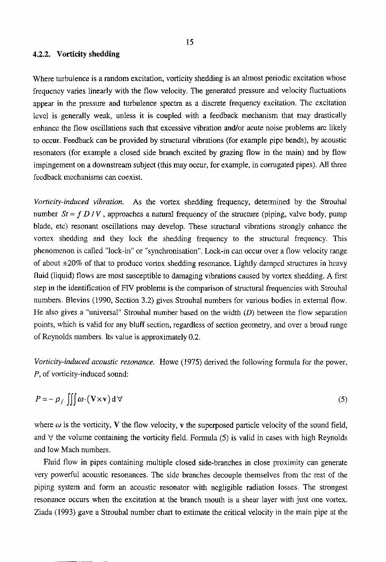
4.2.2. Vorticity shedding
Where turbulence is a random excitation, vorticity shedding is an almost periodic excitation whose
frequency varies linearly with the flow velocity. The generated pressure and velocity fluctuations
appear in the pressure and turbulence spectra as a discrete frequency excitation. The excitation
level is generally weak, unless it is coupled with a feedback mechanism that may drastically
enhance the flow oscillations such that excessive vibration and/or acute noise problems are likely
to occur. Feedback can be provided by structural vibrations (for example pipe bends), by acoustic
resonators (for example a closed side branch excited by grazing flow in the main) and by flow
impingement on a downstream subject (this may occur, for example, in corrugated pipes). All three
feedback mechanisms can coexist.
Vorticity-induced vibration. As the vortex shedding frequency, determined by the Strouhal
number St = f D IV, approaches a natural frequency of the structure (piping, valve body, pump
blade, etc) resonant oscillations may develop. These structural vibrations strongly enhance the
vortex shedding and they lock the shedding frequency to the structural frequency. This
phenomenon is called "lock-in" or "synchronisation". Lock-in can occur over a flow velocity range
of about ±20% of that to produce vortex shedding resonance. Lightly damped structures in heavy
fluid (liquid) flows are most susceptible to damaging vibrations caused by vortex shedding. A first
step in the identification of FIV problems is the comparison of structural frequencies with Strouhal
numbers. Blevins (1990, Section 3.2) gives Strouhal numbers for various bodies in external flow.
He also gives a "universal" Strouhal number based on the width (D) between the flow separation
points, which is valid for any bluff section, regardless of section geometry, and over a broad range
of Reynolds numbers. Its value is approximately 0.2.
Vorticity-induced acoustic resonance. Howe (1975) derived the following formula for the power,
P, of vorticity-induced sound:
P=-p1 JfJm·(Vxv)dV' (5)
where w is the vorticity, V the flow velocity, v the superposed particle velocity of the sound field,
and V' the volume containing the vorticity field. Formula (5) is valid in cases with high Reynolds
and low Mach numbers.
Fluid flow in pipes containing multiple closed side-branches in close proximity can generate
very powerful acoustic resonances. The side branches decouple themselves from the rest of the
piping system and form an acoustic resonator with negligible radiation losses. The strongest
resonance occurs when the excitation at the branch mouth is a shear layer with just one vortex.
Ziada (1993) gave a Strouhal number chart to estimate the critical velocity in the main pipe at the

16
onset of resonance, which includes the effects of diameter ratio, geometry of the side branches and
location of upstream elbows. He discussed counter-measures to reduce the pulsation amplitudes
and he remarked that measured source terms can be incorporated relatively easily into computer
codes of pipe acoustics.
Control valves have the inherent feature that a high-speed jet issues from the vena-contracta.
Another common feature is the smallness of the valve body which, in many cases, provides a
downstream impingement boundary. Flow impingement in valves can cause severe noise problems
and/or acoustic fatigue failures, especially when acoustic modes are excited (Ziada et al 1989).
Ziada et al (1999, 2001) and Schafbuch et al (1997) showed that the separation of low-speed
flows in entrance ports of control valves and upstream elbows can cause acoustic resonance in the
connected piping systems.
Broadband acoustic power, for example generated by high-pressure reduction valves, may cause
acoustic fatigue damage to the downstream piping system. Graf et al (1997) proposed a systematic
approach to predict and reduce the broadband noise level produced by gas throttling devices.
Eisinger (1997) gave a design chart for the prevention of acoustic fatigue failure.
4.2.3. Leakage flow-induced vibration
Leakage flow is an important excitation mechanism that is not directly related to vorticity shedding
and/or turbulence. It occurs, for example, in liquid control valves. When these valves are nearly
closed, the local high-velocity leakage flow may cause an instability with coupled flow and valve
body oscillations. These oscillations may interact with acoustic modes in the piping and with
downstream vortex streets. An upstream nearly-closed or leaking valve is generally less stable than
a downstream one (Miller 1970; Mulcahy 1983, 1988).
Weaver et al (2000) address this subject very briefly.
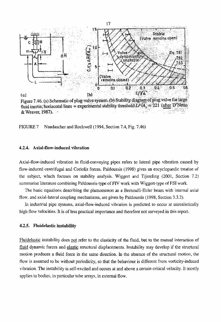
Naudascher and Rockwell (1994, Section 7.4) give a nice introduction. Figure 7 is from their
book. The left figure shows the system, the right one the corresponding stability diagram. The
symbols in the stability diagram are explained in the sketch of the system, with y the specific
weight of the liquid.
For further information, see Blevins (1990, Section 1 0.4.2), Chen (1987, Section 6.1 0) and Au
Yang (2001, Sections 10.5 and 10.6).
17
(a) JbL · . . , Figure 7 .46. (a) Schematicof plug;.ya}y~sy$t~~)Sta~l1ity fluid inertia; hori:zontAlli~es = e~perlniental sta~ility thresh· . &Weaver, 1987).
FIGURE 7 Naudascher and Rockwell (1994, Section 7.4, Fig. 7.46)
4.2.4. Axial-flow-induced vibration
lqg;valvefor:latg$~ 21 (aft¢t; J;i';Netto,
~-' '--"~:,::·>::::-:::7':"-.::--'~----
Axial-flow-induced vibration in fluid-conveying pipes refers to lateral pipe vibration caused by
flow-induced centrifugal and Coriolis forces. PaYdoussis (1998) gives an encyclopaedic treatise of
the subject, which focuses on stability analysis. Wiggert and Tijsseling (2001, Section 7.2)
summarise literature combining Pai'doussis-type of FIV work with Wiggert-type of PSI work.
The basic equations describing the phenomenon as a Bernoulli-Euler beam with internal axial
flow, and axial-lateral coupling mechanisms, are given by PaYdoussis (1998, Section 3.3.2).
In industrial pipe systems, axial-flow-induced vibration is predicted to occur at unrealistically
high flow velocities. It is of less practical importance and therefore not surveyed in this report.
4.2.5. Fluidelastic instability
Fluidelastic instability does not refer to the elasticity of the fluid, but to the mutual interaction of
fluid dynamic forces and elastic structural displacements. Instability may develop if the structural
motion produces a fluid force in the same direction. In the absence of the structural motion, the
flow is assumed to be without periodicity, so that the behaviour is different from vorticity-induced
vibration. The instability is self-excited and occurs at and above a certain critical velocity. It mostly
applies to bodies, in particular tube arrays, in external flow.

18
4.3. The textbooks
What the standard textbooks on FIV say about internal pipe flow is shortly summarised in this
section.
Chen (1987)
Some general principles for a better understanding of FIV are given in the Sections 2.1 and 2.14.
Fluid viscosity, fluid compressibility and a free surface may cause damping of a vibrating structure
surrounded by fluid. To be more precise: 1) in an incompressible in viscid fluid without surface
waves, there is no damping and a positive added mass, 2) in a compressible inviscid fluid in a
confined region, there is no damping, because energy cannot radiate away, 3) in a compressible
inviscid fluid in an unconfined region, there is radiation damping, and 4) in compressible fluids,
there are acoustic modes, so that the added mass may be positive or negative.
Chapter 4 describes circular cylindrical shells containing fluid. Shell theory for the pipe is
combined with potential flow theory for the fluid through interface conditions at the inner pipe
wall. A harmonic analysis of infinitely long pipes gives phase velocities, modes of vibration and
amplitude ratios. Waterhammer and precursor waves are discussed on the pages ll8-120, and
bending waves on the pages 120-122.
Chapter 5 describes pipes conveying fluid. This refers to what is called Pa'idoussis-type of FIV
work in the present Section 4.2.4. Beam theory for the pipe, combined with plug flow for the fluid,
is used in stability analyses. Section 5.3.3.3 explains the role of the Coriolis force, which is a
damping mechanism in non-conservative systems at low flow velocities. Section 5.6 mentions
waterhammer.
Blevins (1990)
Chapter 10 describes vibrations of a pipe containing a fluid flow. The introduction on page 384
mentions waterhammer, valve chatter, pipe whip and leakage flow.
Section 10.1.1 on instability of fluid-conveying pipes is the Pa'idoussis-type of FIV work (see
present Section 4.2.4). Equation (10-27) gives a good estimate of the influence of a steady flow on
the frequency, m 1 , of the first natural mode of lateral vibration of a simply supported pipe:
(6)
where V is the flow velocity, Vc is the critical velocity at which the pipe buckles, and mN is the
natural frequency for V = 0. A simply-supported pipe will buckle because of the centrifugal force,
19
at m1 = 0, but a cantilever pipe will flutter because of the Coriolis force, at m1 > 0. These are
different kinds of instabilities. Table 10-1 gives the stability behaviour of differently supported
pipes.
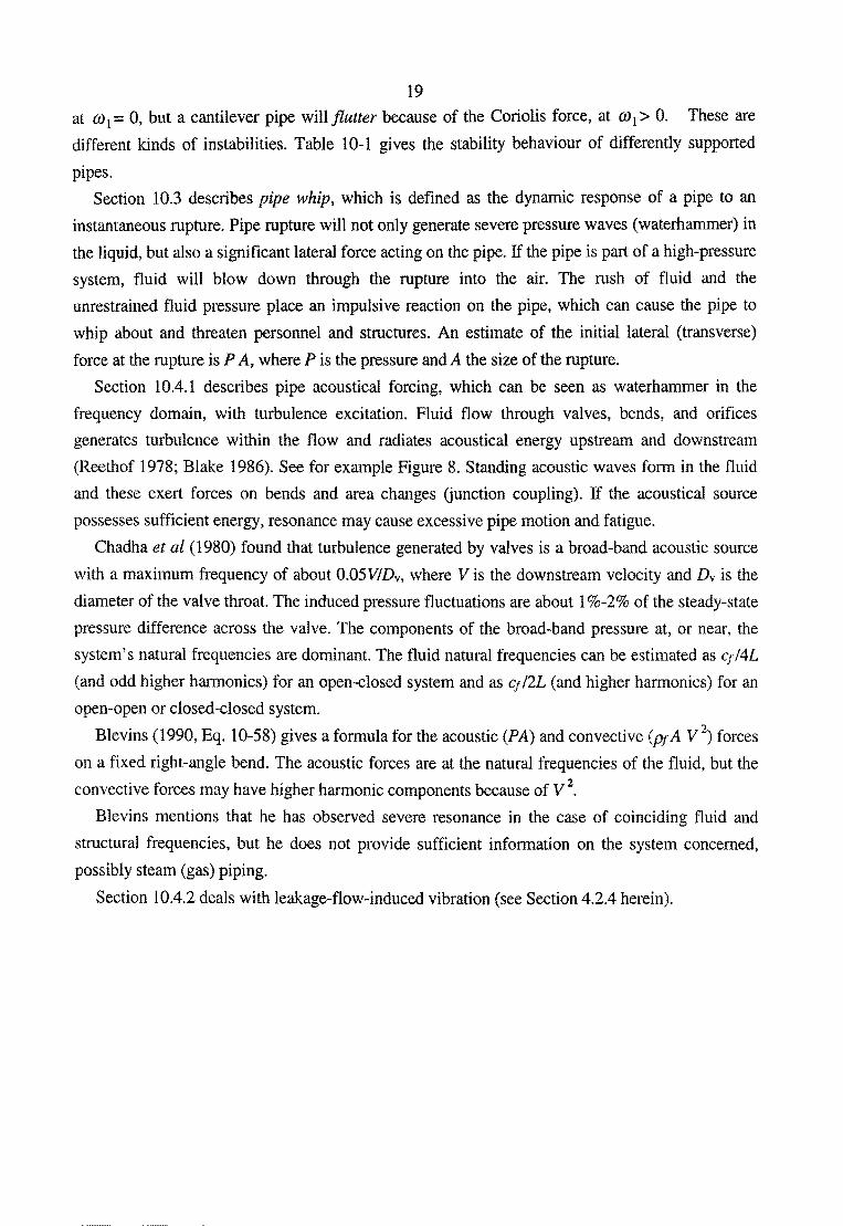
Section 10.3 describes pipe whip, which is defined as the dynamic response of a pipe to an
instantaneous rupture. Pipe rupture will not only generate severe pressure waves (waterhammer) in
the liquid, but also a significant lateral force acting on the pipe. If the pipe is part of a high-pressure
system, fluid will blow down through the rupture into the air. The rush of fluid and the
unrestrained fluid pressure place an impulsive reaction on the pipe, which can cause the pipe to
whip about and threaten personnel and structures. An estimate of the initial lateral (transverse)
force at the rupture is P A, where P is the pressure and A the size of the rupture.
Section 1 0.4.1 describes pipe acoustical forcing, which can be seen as waterhammer in the
frequency domain, with turbulence excitation. Fluid flow through valves, bends, and orifices
generates turbulence within the flow and radiates acoustical energy upstream and downstream
(Reethof 1978; Blake 1986). See for example Figure 8. Standing acoustic waves form in the fluid
and these exert forces on bends and area changes (junction coupling). If the acoustical source
possesses sufficient energy, resonance may cause excessive pipe motion and fatigue.
Chadha et al (1980) found that turbulence generated by valves is a broad-band acoustic source
with a maximum frequency of about 0.05V!Dv, where Vis the downstream velocity and Dv is the
diameter of the valve throat. The induced pressure fluctuations are about 1%-2% of the steady-state
pressure difference across the valve. The components of the broad-band pressure at, or near, the
system's natural frequencies are dominant. The fluid natural frequencies can be estimated as q/4L
(and odd higher harmonics) for an open-closed system and as q/2L (and higher harmonics) for an
open-open or closed-closed system.
Blevins (1990, Eq. 10-58) gives a formula for the acoustic (PA) and convective (PfA V 2) forces
on a fixed right-angle bend. The acoustic forces are at the natural frequencies of the fluid, but the
convective forces may have higher harmonic components because of V 2•
Blevins mentions that he has observed severe resonance in the case of coinciding fluid and
structural frequencies, but he does not provide sufficient information on the system concerned,
possibly steam (gas) piping.
Section 10.4.2 deals with leakage-flow-induced vibration (see Section 4.2.4 herein).

20
)
~ Turbulent PressQr'$
Field · (Shocks}
Figure 1 Schematic representation of valve noise generation and propagation.
FIGURE 8 (Reethof 1978, Fig. 1)
Naudascher and Rockwell (1994)
In their introduction, Naudascher and Rockwell give a strategy to identify possible flow-induced
vibrations in a system. First, search for 1) all body oscillators, 2) all fluid oscillators, 3) all sources
of extraneously induced excitation, 4) all sources of instability-induced excitation, and 5) all
sources of movement-induced vibration. Second, assess all possible combinations of structural and
fluid oscillations arising from (1) and (2) in conjunction with the excitations (3), (4) and (5). The
coincidence of natural frequencies makes the combination of body and fluid oscillators dangerous,
although in liquid flows FSI tends to separate coinciding fluid and structural frequencies.
Estimating these natural frequencies, and finding the dominant excitation frequencies, is an integral
part of the identification process.
A useful aid in preliminary investigations of danger spots and dangerous operating conditions of
a system is a global or lumped-parameter analysis as suggested by Naudascher and Rockwell
(1980) and as performed by, e.g., Wood (1968, 1969), Schumann (1979), Erath et al (1998), and
Moussou et al (2000).
Section 7.4 gives a good introduction to leakage-flow-induced vibration. Press-open and press
shut devices are devices controlling the flow through small openings such that the fluid force tends
to press them either open or shut. One should take care with these devices, because, if they are
lightly damped, they may vibrate due to leakage-flow pulsations. More specific: valves controlling
the outflow from a Helmholtz resonator of negligible fluid inertia are susceptible to movement
induced excitation if they act as press-open devices. And: devices controlling flow through small
openings are susceptible to movement-induced excitation if they are press-shut and exposed to

21
large fluid-inertia effects from the adjacent flow passage.
Chapter 8 describes fluid oscillators. The Sections 8.2 and 8.4 consider classical waterhammer
theory in the frequency domain (Wylie and Streeter 1993). Section 8.5.2 describes various filters to
attenuate fluid oscillations. Some practical examples are given in Section 8.6.1.
Au-Yang (2001)
Section 10.4 gives a short and clear introduction to the stability of pipes containing flowing fluid:
this is the Pa1doussis-type ofFIV work. Example 10.3 concerns a 18m long, 1m diameter, 58 mm
thick, water-filled, steel pipe, for which the critical velocity, Vc, is about 500 m/s.
The Sections 10.5 and 10.6 treat leakage-flow-induced vibration. Figures 9(A)(B) show
common taps. If the threads are worn, the spindle may experience violent vibration that can shake
the attached water pipe (waterhammer). Figure 10 shows the acceleration signal obtained from a
piston check valve of the type shown in Figure 9(C). The signal exhibits a leakage-flow-induced
instability.
Flow
(A)
Wall
(B)
Figure I 0.9 Con,ponents that have experience leak:age-flow-induoed instability (A) Common faucet; (B) Frost;.proof, outdoor faucet; (C) LUlc;;heck valve:
(to be continue4)
FIGURE9 (Au-Yang 2001, Section 1 0.6, Fig. 1 0.9)

g
4.0
2.0
·2.0
22
2.5 sec 7.5sec
Figure 1 O.l 0 Vibration signature from an accelerometer mounted on a piston check valve showing leakage-flow-induced instability
FIGURE 10 (Au-Yang 2001, Section 10.6, Fig. 10.10)
Chapter 12 discusses acoustically induced vibration and noise. Acoustically induced vibration is
probably one of the most common vibration problems in the power and process industries. Piping
systems, vessels, valve cavities, heat exchanger internals, and many other components are potential
resonators in which standing waves can form, while pumps, valves, elbows, orifices, etc, all have
the potential to excite these standing waves. Once resonance occurs, the resulting sound intensity
in most cases asks for remedial action. In some cases, acoustic excitation can cause rapid fatigue
failure of piping welded points, valve internal parts and other components. The case studies in
Section 12.10 are most interesting. Case Study 12.2, taken from Ziada et al (1999, 2001), concerns
acoustic noise generated by a spherical elbow. Case Study 12.3, taken from Coffman and Bernstein
(1979), concerns acoustic resonance in valve cavities. Standing waves in the cavities of relief
valves, excited by the flow over them, turned out to be destructive for the valve components. The
problem was solved by replacing a cylindrical nozzle by a conical one. Case Study 12.5, taken
from Pastorel et al (2000), concerns valve-generated acoustic waves in a pipe. Acoustic fatigue
caused cracks in the pipes downstream of the control valves.
Gibert (1988)
Chapter 19 gives an acoustic analysis of the low-frequency behaviour of fluid-filled pipe systems.
All kinds of acoustic sources, mainly of the turbulent/acoustic nature, are described. Section 19.5
23
gives a practical example. This book is well known at EDF and not further summarised here.
Morand and Ohayon (1995)
Morand and Ohayon (1995) give a thorough mathematical and numerical treatment of general
FSI/FN problems without special reference to fluid-conveying pipe systems.
Pai'doussis (1998)
Pa'idoussis's book is on axial-flow-induced vibration as discussed in Section 4.2.4 herein.
5. EXCITATION SOURCES: SUMMARY
Many excitation mechanisms exist. Here is an overview of what was found in the literature
consulted. A distinction is made between exciters of the fluid and exciters of the piping. Of course,
if PSI takes place in a significant manner, both fluid and piping will be excited. The excitation can
be transient, periodic or random.
Types of excitation (from Wylie and Streeter 1993, pp. 309-313)
Resonance develops only when there is an exciter present at some point in the system. The form
that the exciter takes can generally be placed into one of two categories. The first and most
common is an explicit device that acts as a forcing function exciting the system at some frequency.
The second type is one that responds to the system. The oscillations produced by this type are
generally referred to as self-excited, as the implicit exciter is an integral part of the entire physical
system.
5.1. Exciters for the fluid
Transient
valve action (closure I opening) (control valves, check valves, relief valves, etc)
pump action (shut off I start up)
turbine action (load rejection)
column separation (collapse)
steam-condensation (e.g. Chun and Yu 2000)
pipe break (generating severe waterhammer)
24
rupture-disk break (generating severe waterhammer)
blast I explosion
collision (with other pipe, with vehicle)
bend I junction motion
priming I start up I slug flow
Periodic
vortex-shedding (Section 4.2.2)
leakage-flow (Section 4.2.3)
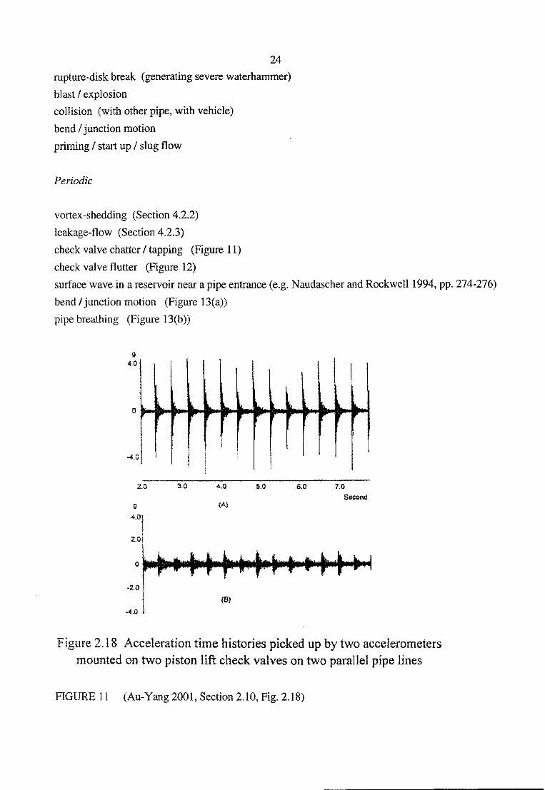
check valve chatter I tapping (Figure 11)
check valve flutter (Figure 12)
surface wave in a reservoir near a pipe entrance (e.g. Naudascher and Rockwell1994, pp. 274-276)
bend I junction motion (Figure 13(a))
pipe breathing (Figure 13(b))
g 4,0
0 l .. ..,. ,. PI'
-4.0
2.0 4,0
g (A)
-2.0
(S}
-4,0
II. ... l, lt, ,. ""
,. r
5.0
k.. pr
6.0
l L .. r ..
7.0
Se<::Ofltl
Figure 2.18 Acceleration time histories picked up by two accelerometers mounted on two piston lift check valves on two parallel pipe lines
FIGURE 11 (Au-Yang2001, Section 2.10, Fig. 2.18)

25
64.0 Disc Flutter
I\ '"
Second
Figure 2.5 Flutter of a check valve disk measured by UT instrument (Au-Yang, 1993)
FIGURE 12 (Au-Yang 2001, Section 2.4, Fig. 2.5)
(a)
Figure 13-31 Capacitance elements.
FIGURE 13 (Wylie and Streeter 1993, Section 13-8, Fig. 13-31)
Random
turbulence (Section 4.2.1)
cavitation
two-phase flow
(b)
5.2. Exciters for the piping
Transient
waterhammer
column separation
earthquake
landslide
26
pipe whip (rupture of flexible pipe, where the rupture generates lateral forces that make the pipe
heavily whip I flail/ shake, see Blevins 1990, Section 1 0.3)
blast I explosion
collision (with other pipe, with vehicle)
bend I junction motion
priming I start up I slug flow
Periodic
machine vibration
axial-flow-induced vibration (Section 4.2.4)
lock-in (see Section 4.2.2)
bend I junction motion
Random
seismic motion
base motion
wind
6. EXCITATION SOURCES: VffiRATING BENDS AND BRANCHES
6.1. Introduction
Vibrating pipe junctions, in particular bends (elbows) and branches (tee-pieces), but also dead
ends, are the most significant FSI mechanisms in liquid-filled pipe systems. Axially vibrating
junctions generate pressure waves in the fluid, and pressure waves make unrestrained junctions
vibrate. Section 6.2 attempts to list all physical experiments with respect to FSI in single-elbow

27
pipe systems. Some aspects of mathematical and numerical modelling are discussed. Section 6.3
lists the few FSI experiments that have been performed in branched systems.
6.2. Bends
List in chronological order of experimental studies of FSI in one-elbow pipe systems:
Blade et al (1962);
Swaffield (1968-1969);
Davidson and Smith (1969);
Wood and Chao (1971);
Davidson and Samsury (1972);
A-Moneim and Chang (1979);
Kellner et al (1983);
Otwell (1984), Wiggert et al (1985);
Liu and Ohashi (1988);
Yamaguchi and Kondo (1989);
Tentarelli (1990), Brown and Tentarelli (2001);
Tijsseling (1993), Tijsseling et al (1996);
de Jong (1994, 2000);
Svingen (1996);
Repp (1998);
Jiao et al ( 1999);
Altstadt et al (2000);
Tijsseling AS and Vaugrante P (2001);
Caillaud et al (200 I)
Note: The much-used experimental data of Swaffield (1968-1969) and Davidson and Smith (1969)
are not valid, as will be explained below.
Many physical experiments have been performed in systems with elbows, ranging from Blade et al
(1962) to Caillaud et al (2001). Nearly all of the experimental systems had at least one "fixed" end
(support, anchor), for example the connection of the test pipe to a liquid supply (reservoir). "Fixed"
stands for infinitely large impedance (zero mobility), something impossible in practice, especially
during resonance. Some researchers, like Davidson and Samsury (1972) and de Jong (1994),
measured the mobility of the pipe supports in their test systems, but it nevertheless is common
practice not to measure or estimate the mobility of supports, but to neglect it on the simplifying
assumption that the support is (looks) rigid. Consequently, many investigators have overlooked

28
support mobility. The well known experiments by Swaffield (1968-1969) and Davidson and Smith
(1969), the results of which have been used by many others, suffer from the ignored vibration of
"fixed" points, as noted by Wilkinson (1980, p. 197) and Brown and Tentarelli (1988, p. 148),
respectively. Svingen (1996, p. 76) reported "unintentional" valve motion. Care has to be taken in
this respect, always. In contrast to the many other test rigs, the experimental apparatus employed by
Tijsseling et al (1996) and Tijsseling and Vaugrante (2001) has no "fixed" points at all, it is
structurally "free".
The fundamental acoustic frequency of a fluid column in a(n) (open) reservoir- pipeline- valve
(closed) system is q14Lerr. The effective length, Lerf, given by Alster (1972, Eq. 40) as
(7)
accounts for added-mass effects at the open (reservoir) end. The semi-empirical formula (7) is
valid for circular ducts of diameter D and length L. It differs from the classical value
1 + 4 I (3n) D I L = 1 + 0.42 D I L given in standard textbooks on acoustics (e.g. Rienstra and
Hirschberg 1999, p. 105).
The correction for added mass has not been made in all of the studies listed above. Although
most of the studies concern laboratory experiments in short pipes, the correction term was
justifiably neglected, because the DIL ratios were small enough.
Aspects of mathematical and numerical modelling
Wiggert and Tijsseling (2001, Section 2) surveyed the mathematical models and numerical
methods that are used to simulate FSI in liquid-filled pipe systems. EDF uses CIRCUS to perform
computations in the frequency domain. CIRCUS is based on a spectral finite-element method. An
alternative approach, based on transfer matrices, has been presented by Tijsseling and Vaugrante
(1999).
One issue of concern is the influence of lumped (concentrated) masses, e.g. due to bends and
branches, on pipe vibration. Lumped masses give rise to (infinitely) large accelerations when
subjected to impact loads, e.g. instantaneous valve closures. In numerical calculations, if 8 t ~
zero, then m I 8t ~infinity (Tijsseling 1993, Section 4.6, Eq. 4.128), indicating the dominance
of lumped inertia. Large narrow peaks appear in the solutions. A continuous representation of
lumped masses (short bends, valves, etc) is not acceptable because their small UD ratios
obstruct the assumption of one-dimensionality. This particularly holds for analysis in the time
domain. In the frequency domain, Tentarelli ( 1990, Section 7.4) has experimented with different
elbow representations. He rejected the lumped-mass approach in favour of two short and stiff
segments representing the elbow. The lengths of the segments were determined by the actual

29
measured length of the elbow and the outer radii were selected such that their total mass
equalled that of the elbow. In general it is difficult to find the mass and stiffness of an elbow, in
particular the moments of inertia are difficult to assess.
A second issue, also addressed by Tentarelli (1990, Section 3.2.2), is numerical instability at
higher frequencies (ill-conditioned matrices, round-off errors, numerical instabilities). This is a
general problem in the frequency-domain solution of lateral beam (pipe) vibration. Tentarelli
(1990, pp. 43-44) and DeJong (1994, p. 41, pp. 54-55) sub-divided pipes into shorter reaches to
prevent numerical problems. Finnveden (1994, pp. 473-474) cured the numerical instability by
choosing appropriate base and shape functions within the FEM. Charley et al (1998, Section 3.2)
studied the matrix condition numbers in their transfer matrix model. For low-frequency flexural
vibration acceptable solutions can be obtained without special measures.
6.3. Branches
List in chronological order of experimental studies of FSI in branched pipe systems:
Wood and Chao (1971);
Merkli P (1978) (air, no FSI, "analytical" solutions, definition of effective lengths);
Kellner et al (1983);
Tentarelli (1990), Brown and Tentarelli (2001);
Vardy et al ( 1996)
There have not been many physical experiments on FSI in branched systems, although the author
has seen quite a few industrial problems in which T -pieces were involved. Some of these had to do
with fatigue, others with combined mechanical-acoustical loading. As usual, these problems have
not been documented for the public. However, it is well known that the connection points of small
bore pipes connected to (vibrating) large bore pipes are points of potential failure (see ASME
B31.3, paragraph 319.6, p. 41).
7. CODES AND STANDARDS
Leslie and Vardy (200 1) inspected many codes and standards with respect to FSI, but they omitted
the important ASME B31 codes. Pothof and McNulty (2001) included these codes in their review,
which, however, was not exclusively dedicated to FSL FSI was considered by Lemmens and
Gresnigt (2001) in the framework of the Standards, Measurements and Testing (SMT) programme
of the European Union.
There is no need to repeat the work done by the above authors. Instead, two recently revised
30
codes will be discussed: the American ASME B31.1 (December 2001) and the Dutch NEN 3650
(August 2001). Furthermore, a few remarks on yield stress criteria.
7.1. ASME B31.1 (December 2001)
This code prescribes minimum requirements for the design, materials, fabrication, erection, test,
and inspection of power and auxiliary service piping systems for electric generation stations,
industrial institutional plants, and central and district heating plants. To my best knowledge, this
latest B31.1 code, does not mention FSI and/or FN.
7.2. NEN 3650 (Parts 1 and 2) (August 2001)
This standard (code) contains requirements for the complete life cycle of pipeline transportation
systems, without regard to the material. It also gives reference to relevant European (EN) and
international (ISO) standards. The standard has recently been updated and it has been open for
comment until 1 December 2001. The comments are presently being used to improve the standard.
Part 1 is general, and Part 2 concerns steel pipelines. Appendix C.2.2 on pages 94-96 of Part 1
mentions three ways of calculating dynamic pressure variations: 1) with the Joukowsky formula, 2)
with a classical waterhammer analysis, and 3) taking into account FSI. The description is very
brief, and WL I Delft Hydraulics has commented to it.
7.3. Stress criteria
Standard yield stress criteria are those ofTresca, Von Mises (1913), Hill (1950) and Vegter (1991).
According to Todhunter and Pearson (1960), Von Mises's material is actually a rediscovery of
work by Levy (see Saint-Venant 1871). Tresca's work was largely experimental (see Saint-Venant
1885). Pijlman (2001, Section 2) gives an introduction to the subject.
8. CURRENT FSI RESEARCH ACTIVITY
If one realises that every paper in the list of 123 references in Wiggert and Tijsseling (2001) has
cost time and money (man-hours), this list gives a good indication of the mainly academic research
activity in this area. The category "FSI- recent work" in the list of References in this report gives
latest papers to be added to Wiggert and Tijsseling's list. Also, the five European projects
mentioned below, and their participating members, give an indication of the viability and
importance of the subject.
Nearly all activity known to the author takes place in Europe, and in particular in Germany, UK

31
and France. Based upon publications, web-sites and personal relations, an overview for Europe:
Universities:
Aberdeen, UK
Bathe, UK
Darmstadt, Germany
Dundee, UK
Eindhoven, The Netherlands
Imperial College, University of London, UK
King's College, University of London, UK
Lille, ENSAM, France
Louvain - Leuven, Belgium
Trondheim, Norway
Research centres:
Forschungszentrum Rossendorf, Dresden, Germany
GMD-SCAI, Sankt Augustin, Germany
UMSICHT, Oberhausen, Germany
TNO, Delft, The Netherlands
WL I Delft Hydraulics, Delft, The Netherlands
Companies:
BASF, Ludwigshafen, Germany
EDF, Clamart, France
ESDU, London, UK
FDB, Trondheim, Norway
Flowmaster, Towcester, UK
Framatome (formerly: Siemens Nuclear Power), Erlangen, Germany
KAE, Bubenreuth, Germany
KED, Rodenbach, Germany
Mannesmann-Demag, Dusseldorf, Germany
European projects:
FLODAC - BRITEIEURAM3, BRPR970394
32
Title: Flow in Duct Acoustics
Coordinator: Prof M Abom, KTH, Royal Institute of Technology, Stockholm, Sweden
Period: 1997-2001
See: Dequand (2001)
LEAKING - GROWTH - G 1RD - 2002 - 00677
Title: Leak detection and reliability-based life prediction of water piping
Coordinator: Dr G Becker, RISA Sicherheitsanalysen GMBH, Berlin, Germany
Period: 2002-2005
SMT4-CT97-2188
Title: Transient pressures in pressurized conduits for municipal water and sewage water
transport
Coordinator: Mr G McNulty, BHR Group Ltd, Cranfield, UK
Period: 1997-2001
SURGE-NET- GROWTH -GIRT- 2002-05069
Title: Organisations involved in the prediction and analysis of fluid transients in pipe systems
Coordinator: Mr D Stewardson, University of Newcastle, UK
Period: 2002-2005
W AHALoads - FIKS-CT-2000-00106
Title: Two-phase flow water hammer transients and induced loads on materials and
structures of nuclear power plants
Coordinator: Prof M Giot, Universite catholique de Lou vain, Belgium
Period: 2000-2003
See: Giot et al (200 1)
USA:
Argonne National Laboratory, Argonne, lllinois
Michigan State University; East Lansing, Michigan
9. UNSOLVEDPROBLEMS
Much work has been done and the basic mechanisms of FSI and FIV are well understood these
days. Areas that need further development are listed below.
33
FSI
priming, start up, slug flow
two-phase flow, cavitation, steam condensation (Giot et al2001)
importance of FSI, guidelines, standards and codes
dynamic behaviour of supports
curved pipes and flexible hoses
plastic pipes, visco-elasticity
unsteady friction
experimental data, empirical relations
See Wiggert and Tijsseling (2001, Section 8)
FIV
turbulence (LES, DNS, LBM instead of k-s)
CFD
experimental data, empirical relations
See Weaver et al (2000, Section 7)
10. CONCLUSION
From a theoretical point of view, FSI and FIV are well understood, and powerful computational
tools exist to simulate the phenomena. From a practical point of view, there is a lack of general
rules and practical guidelines. Each industrial problem has to be examined on a case by case base,
often with the help of specialists.

34
This report is a guide to the vast amount of literature on the subject.
ACKNOWLEDGEMENTS
The author likes to thank Patrick Vaugrante, Pierre Moussou and Sebastien Caillaud for their
critical comments and helpful suggestions.
REFERENCES
History
Allievi L (1902), Teoria generale del moto perturbato dell'acqua nei tubi in pressione. (General
theory of the variable motion of water in pressure conduits.), Annali della Societa degli Ingegneri
ed Architetti Italiani, Milan, Italy (in Italian). (French translation by Allievi himself, in Revue de
Mecanique, Paris, 1904; German translation by R Dubs and V Bataillard, 1909, Berlin: Springer.)
Boulanger A (1913), Etude sur la propagation des ondes liquides dans les tuyaux elastiques. (Study
on the propagation of liquid waves in elastic tubes.), Travaux et Memoires de l'Universite de Lille,
Nouvelle Serie, II. Medecine-Sciences 8, Lille: Tallandier, Paris: Gauthier-Villars (in French).
Joukowsky N (1898), Uber den hydraulischen Stoss in Wasserleitungsrohren. (On the hydraulic
hammer in water supply pipes.), Memoires de l'Academie Imperiale des Sciences de
St. -Petersbourg, 1900, Series 8, 9(5) (in German). (English translation, partly, by 0 Simin: Water
hammer, Proceedings of the 24th Annual Convention of the American Water Works Association,
St. Louis, USA, June 1904, 341-424; French translation, partly, by M Goupil: Notice sur les
principaux travaux concernant le coup de belier et specialement sur le memoire et les experiences
du Professeur N. Joukovsky (1898), Annales des Pants et Chaussees, 1907, 199-221.)
Korteweg DJ (1878), Ueber die Fortpflanzungsgeschwindigkeit des Schalles in elastischen Rohren
(On the velocity of propagation of sound in elastic pipes), Annalen der Physik und Chemie New
Series 5 525-542 (in German).
Kries J von (1883), Ueber die Beziehungen zwischen Druck und Geschwindigkeit, welche bei der
Wellenbewegung in elastischen Schlauchen bestehen (On the relations between pressure and
velocity, which exist in the wavelike motion in elastic tubes), Festschrift der 56. Versammlung
Deutscher Natwforscher und Arzte gewidmet von der Naturforschenden Gesellschaft zu Freiburg
i. B., Akademische Verlagsbuchhandlung von JCB Mohr, Freiburg in Breisgau und Tiibingen,
35
Germany, 67-88 (in German).
von Kries J (1892), Studien zur Pulslehre, Akademische Verlagsbuchhandlung von JCB Mohr,
Freiburg in Breisgau und Tiibingen, Germany (in German).
Lamb H (1898), On the velocity of sound in a tube, as affected by the elasticity of the walls,
Memoirs of the Manchester Literary and Philosophical Society, Manchester, UK, 42(9) 1-16.
Lambossy P (1950), Apen;u historique et critique sur le probleme de la propagation des ondes dans
un liquide compressible enferme dans un tube elastique - Premiere partie, Helvetica Physiologica
et Pharmacologica Acta 8 209-227 (in French).
Lambossy P (1951), Apen;u historique et critique sur le probleme de la propagation des ondes dans
un liquide compressible enferme dans un tube elastique - Deuxieme partie, Helvetica Physiologica
et Pharmacologica Acta 9 145-161 (in French).
Skalak R (1956), An extension of the theory of waterhammer, Transactions of the ASME 78
105-116.
Todhunter I and Pearson K (Volume I, 1886; Volume II, Parts I and II, 1893), A History of
Elasticity and Strength of Materials, Cambridge University Press, England. Reprinted as: A
History of the Theory of Elasticity and of the Strength of Materials -from Galilei to Lord Kelvin,
Dover Publications, New York, 1960.
FSI - reviews
Leslie DJ and Tijsseling AS (1999), A review of modelling damping mechanisms in coupled
liquid-pipe vibrations, Proceedings of the 3rd ASME & JSME Joint Fluids Engineering
Conference, Symposium S-290 Waterhammer (Editor JCP Liou), San Francisco, USA, ASME
FED 248 1-8. (54 Refs)
Tijsseling AS (1996), Fluid-structure interaction in liquid-filled pipe systems: a review, Journal of
Fluids and Structures 10 109-146. (248 Refs)
Wiggert DC ( 1986), Coupled transient flow and structural motion in liquid-filled piping systems: a
survey, Proceedings of the ASME Pressure Vessels and Piping Conference, Chicago, USA, Paper
86-PVP-4. (29 Refs)
36
Wiggert DC (1996), Fluid transients in flexible piping systems: a perspective on recent
developments, Proceedings of the 18th IAHR Symposium on Hydraulic Machinery and Cavitation,
Valencia, Spain, 58-67. (26 Refs)
Wiggert DC and Tijsseling AS (2001), Fluid transients and fluid-structure interaction in flexible
liquid-filled piping, ASME Applied Mechanics Reviews 54 455-481. (123 Refs)
Zhang L, Huang W, and Tijsseling AS (2000b), Review of FSI analysis of fluid-conveying pipes,
Journal of Hydrodynamics, Series A 15(3) 366-379 (in Chinese). (97 Refs)
FSI- recent work (1997-2002)
Altstadt Mossner T, and Weiss R (2000), The cold water hammer test facility (CWHTF),
Forschungszentrum Rossendorf e.V., Institute for Safety Research, Annual Report 2000, Dresden,
Germany.
Bahrar B, Rieutord E, Morel R, and Zeggwagh G (1998a), Modeling of the waterhammer
phenomenon with respect to real pipe behavior, La Houille Blanche - Revue Internationale de
l'Eau 53 18-25 (in French).
Bahrar B, Rieutord E, and Morel R (1998b), Influence de la viscoelasticite de la paroi sur les
phenomenes classiques de coup de belier, La Houille Blanche - Revue Internationale de l'Eau 53
26-32 (in French).
Bergant A and Tijsseling AS (2001), Parameters affecting water hammer wave attenuation, shape
and timing, Proceedings of the lOth International Meeting of the IAHR Work Group on the
Behaviour of Hydraulic Machinery under Steady Oscillatory Conditions, Trondheim, Norway,
PaperC2.
Charley J, Carta F, and Ould Abdallahi M (1998), Fluid-structure interaction: vibroacoustical
analysis of flow in piping system, Proceedings of the ASMEIJSME Joint Pressure Vessels and
Piping Conference, San Diego, USA; Published as: Advances in Fluids, Structures and
Fluid/Structure Interactions, ASME PVP 377-1, 245-252.
Charley J and Carta F (2001), Application of the auto- and cross-power spectra to hydro- and
aeroacoustics, Mechanical Systems and Signal Processing 15(2) 399-417.
Chun M-H and Yu S-0 (2000), A parametric study and a guide chart to avoid condensation-

37
induced water hammer in a horizontal pipe, Nuclear Engineering and Design 201239-257.
Diesselhorst T, Schmidt R, and Schnellhammer W (2000), Realistic calculation of pressure surges.
Inclusion of dynamic friction and fluid/structure interaction, 3R international 39 678-682 (in
German).
Erath W, Nowotny B, and Maetz J (1998), Simultaneous coupling of the calculation of pressure
waves and pipe oscillations, 3R international37 501-508 (in German).
Formaggia L, Gerbeau JF, Nobile F, and Quarteroni A (2001), On the coupling of 3D and 1D
Navier-Stokes equations for flow problems in compliant vessels, Computer Methods in Applied
Mechanics and Engineering 191561-582.
Giot M (UCL, Louvain-la-Neuve), Prasser HM (FZR, Dresden), Dudlik A (Fraunhofer,
UMSICHT, Oberhausen), Ezsol G (KFKI, Budapest), Habip M (Framatome ANP, Offenbach),
Lemonnier H (CEA, Grenoble), Tiselj I (Institut Jozef Stefan, Ljubljana), Castrillo F (Iberdrola,
Madrid), Van Hove W (Tractebel, Brussels), Perezagua R (Empresarios Agrupados, Madrid), and
Potapov S (EDF, Clamart) (2001), Two-phase flow water hammer transients and induced loads on
materials and structures of nuclear power plants (W AHALoads), Proceedings of Conference FISA-
2001- EU Research in Reactor Safety, Luxembourg, 12-14 November 2001.
Hansson P-A and Sandberg G (2001), Dynamic finite element analysis of fluid-filled pipes,
Computer Methods in Applied Mechanics and Engineering 190 3111-3120.
Hara F (1988), Seismic vibration analysis of fluid-structure interaction in LMFBR piping systems,
ASME Journal of Pressure Vessel Technology 110 177-181.
Ichchou MN, Khamlichi A, Jezequel L, and Tephany F (1998), Elastic-plastic strain in a frame
pipe system under water hammer loads: analysis and parametric study, Proceedings of the
ASME/JSME Joint Pressure Vessels and Piping Conference, July'98, San Diego, USA, ASME
PVP 366 165-172.
Ichchou MN, Jezequel L, and Tephany F (1999), Elastic-plastic dynamics of a frame pipe,
Proceedings of the ASME Pressure Vessels and Piping Conference, August'99, Boston, USA,
ASME-PVP 394 209-217.
Jiao Z, Hua Q, and Yu K (1999), Frequency domain analysis of vibrations in liquid-filled piping
systems, Proceedings of the ASME International Mechanical Engineering Congress and

38
Exposition, November'99, Nashville, USA, ASME-FPST 6 25-31.
Kollmann D, Hirsch 0, and Ungar K (1998), Einsparung von Rohrhalterungen durch
rechentechnische Optimierung des Halterungskonzeptes. (Reduction of pipe supports through
computationally optimising of the pipe support concept.), 3R international 37(8) 528-534 (in
German).
Kollmann D and Swidersky H (2000a), Pressure wave loads on cooler elements taking into
account fluid structure interaction (FSI), KAE Report 1(2), KAE Kraftwerks- und Anlagen
Engineering GmbH, Bubenreuth, Germany.
Kollmann D and Swidersky H (2000b ), Fluid-structure-interaction (FSI) at a connection line
between pre- and main pump of a feedwater system, KAE Report 1(4), KAE Kraftwerks- und
Anlagen Engineering GmbH, Bubenreuth, Germany.
Moussou P and Boyelle H (1999), Analysis of the vibrations of a complete French PWR power
plant piping system, Proceedings of the ASME Pressure Vessels and Piping Conference,
August'99, Boston, USA, ASME-PVP 389 415-422.
Moussou P, Vaugrante P, Guivarch M, and Seligmann D (2000), Coupling effects in a two elbows
piping system, Proceedings of the 7th International Conference on Flow Induced Vibrations,
Lucerne, Switzerland, 579-586.
Munjal ML and Thawani PT (1997), Acoustic analysis and design of compliant cable-hose
systems, Noise Control Engineering Journal45(6) 235-242.
Repp T ( 1998), Fluiddynamic waterhammer simulations with consideration of fluid-structure
interaction, Forschungszentrum Rossendorf e.V., Institute for Safety Research, Annual Report
1998, Dresden, Germany.
Shu D, Deng J, and Zhao Y (2001), Investigation of pressure in pipe subjected to axial-symmetric
pulse loading, International Journal of Impact Engineering 25 523-536.
Tijsseling AS and Vaugrante P (1999), Frequency-domain and time-domain analysis of liquid
filled pipe systems, EDF-DRD Technical Note HP-54/99/030/A, June'99, Clamart, France, 162
pages.
Tijsseling AS and Heinsbroek AGTJ (1999), The influence of bend motion on waterhammer

39
pressures and pipe stresses, Proceedings of the 3rd ASME & JSME Joint Fluids Engineering
Conference, Symposium S-290 Water Hammer (Editor JCP Liou), San Francisco, USA, July'99,
ASME-FED 248 Paper FEDSM99-6907, 1-7, ISBN 0-7918-1961-2 (CD-ROM) or ISBN 0-7918-
1978-7.
Uspuras E, Kaliatka A, and Dundulis G (2001), Analysis of potential waterharnmer at the Ignalina
NPP using thermal-hydraulic and structural analysis codes, Nuclear Engineering and Design 203
1-12.
Vatkova G, Meynen S, and Schafer M (1999), Numerical simulation of fluid-structure interaction
in pipe systems, Proceedings of the Second Workshop on Large-Scale Scientific Computations,
June'99, Sozopol, Bulgaria; Published as: Large Scale Scientific Computations of Engineering and
Environmental Problems II, M Griebel, S Margenov and P Yalamov (eds), Vieweg, Braunschweig,
Germany, (2000), 414-421, ISBN 3-528-03144-1.
Zhang L, Huang W, and Tijsseling AS (2000a), Frequency spectrum analysis of liquid-filled pipes
under waterhammer-induced FSI, Engineering Mechanics 17(1) 1-12 (in Chinese).
FSI - earlier work (before 1997)
Chen SS and Rosenberg GS (1974), Free vibrations of fluid-conveying cylindrical shells, Journal
of Engineering for Industry 96(2) 420-426.
Kellner A and Schonfelder C (1982), Die Bedeutung der Fluid./Struktur-Wechselwirkung fiir die
DruckstoBbelastung von Rohrleitungen. (The effect of fluid/structure-interaction on pressure pulse
loads on pipes.), 3R intemational21443-449 (in German).
Muller WCh ( 1989), DAPS, a code for coupled analysis of pressure transients in pipes,
Kemtechnik 54(3) 149-152.
Reissner E ( 1955), On transverse vibrations of thin, shallow elastic shells, Quarterly of Applied
Mathematics 8 169-176.
Schumann U ( 1979), Fluid-structure interactions in one-dimensional linear cases, Research Report
KfK 2723 B, Kemforschungszentrum Karlsruhe, Germany, 70 pages, ISSN 0303-4003.
Stoessel JC, Keowen RS, and Ibanez P (1988), Visco-elastic pipe support effect on water hammer
induced loads, Proceedings of the ASME Pressure Vessels and Piping Conference, June'88, New

40
York, USA, ASME-PVP 144 279-281.
Thompson JM, Mallett RH, and Ennis WE ( 1989), Analysis of a piping reactions due to
waterhammer loads, Proceedings of the 4th International ANSYS Conference and Exhibition,
May'89, Pittsburgh, USA, Part 1, 15.50-15.90.
Wood DJ (1968), A study of the response of coupled liquid flow-structural systems subjected to
periodic disturbances, ASME Journal of Basic Engineering 90 532-540.
Wood DJ (1969), Influence of line motion on waterhammer pressures, ASCE Journal of the
Hydraulics Division 95 941-959.
Y arnaguchi A, Kondo S, and Togo Y ( 1982), Pseudo two-dimensional analysis of fluid-structure
interaction due to pressure wave propagation in straight pipe, Journal of Nuclear Science and
Technology 19(10) 845-851.
FSI ~ single~elbow experiments and single-branch experiments
A-Moneim MT and Chang YW (1979), Comparison of ICEPEL predictions with single-elbow
flexible piping system experiment,ASME Journal of Pressure Vessel Technology 101142-148.
Blade RJ, Lewis W, and Goodykoontz JH (1962), Study of a sinusoidally perturbed flow in a line
including a 90° elbow with flexible supports, Washington: National Aeronautics and Space
Administration, Technical Note D-1216.
Brown Ff and Tentarelli SC (1988), Analysis of noise and vibration in complex tubing systems
with fluid-wall interactions, Proceedings of the 43rd National Conference on Fluid Power,
Chicago, USA, 139-149.
Brown Ff and Tentarelli SC (2001), Dynamic behavior of complex fluid-filled tubing systems
Part I: Tubing analysis, Journal of Dynamic Systems, Measurement, and Contro/123 71-77.
Caillaud S, Coudiere F, Guillou J, and Vaugrante P (2001), Experimental and numerical analysis
of a single elbow pipe filled with water, EDF-DRD Technical Note HT-62/01/019/A, January'02,
Clamart, France, 37 pages.
Davidson LC and Smith JE ( 1969), Liquid-structure coupling in curved pipes, The Shock and
Vibration Bulletin, No. 40, Part 4, 197-207.
41
Davidson LC and Samsury DR (1972), Liquid-structure coupling in curved pipes - IT, The Shock
and Vibration Bulletin, No. 42, Part 1, 123-136.
Finnveden S (1994), Exact Spectral Finite Element analysis of stationary vibrations in a railway car
structure, Acta Acustica 2 461-482.
de Jong CAF (1994, 2000), Analysis of pulsations and vibrations in fluid-filled pipe systems, Ph.D.
Thesis, Eindhoven University of Technology, Department of Mechanical Engineering, Eindhoven,
The Netherlands (Errata: April 2000).
Kellner A, Voss J, and Schoenfelder C (1983), Fluid/structure-interaction in piping systems:
experiment and theory. Transactions of SMiRT7, Chicago, USA, August 1983, Paper B 4/3, 193-
199.
Liu GL and Ohashi H (1988), Fluid/structure interaction in a two-dimensional bend during
hydraulic transients, Proceedings of the 14th Symposium on Progress within Large and High
Specific Energy Units, Trondheim, Norway, June'88, Vol. 1, 229-240, ISBN 82-519-08521-1.
Merkli P (1978), Acoustic resonance frequencies for aT-tube, Journal of Applied Mathematics
and Physics (ZAMP) 29 486-498.
Ohayon R ( 1986), Variational analysis of a slender fluid-structure system: the elasto-acoustic beam
- A new symmetric formulation, International Journal for Numerical Methods in Engineering 22
637-647.
Otwell RS (1984), The effect of elbow restraint on pressure transients, Ph.D. Thesis, Michigan
State University, Department of Civil and Sanitary Engineering, East Lansing, USA.
Svingen B (1996), Fluid structure interaction in piping systems, Ph.D. Thesis, The Norwegian
University of Science and Technology, Faculty of Mechanical Engineering, Trondheim, Norway.
Swaffield JA (1968-1969), The influence of bends on fluid transients propagated in incompressible
pipe flow, Proceedings ofthe Institution of Mechanical Engineers 183 603-614.
Tentarelli SC (1990), Propagation of noise and vibration in complex hydraulic tubing systems,
Ph.D. Thesis, Lehigh University, Department of Mechanical Engineering, Bethlehem, USA.
42
Tijsseling AS (1993), Fluid-structure interaction in case of waterhammer with cavitation, Ph.D.
Thesis, Delft University of Technology, Faculty of Civil Engineering, Communications on
Hydraulic and Geotechnical Engineering, Report No. 93-6, ISSN 0169-6548, Delft, The
Netherlands.
Tijsseling AS, Vardy AE, and Fan D (1996), Fluid-structure interaction and cavitation in a single
elbow pipe system, Journal of Fluids and Structures 10 395-420.
Tijsseling AS and Vaugrante P (2001), FSI in L-shaped and T-shaped pipe systems, Proceedings of
the lOth International Meeting of the IAHR Work Group on the Behaviour of Hydraulic Machinery
under Steady Oscillatory Conditions, Trondheim, Norway, Paper C3. (Also TUE-RANA 01-19
and EDF-DRD HT -62/01/022/ A).
Vardy AE, Fan D, and Tijsseling AS (1996), Fluid/structure interaction in aT-piece pipe, Journal
of Fluids and Structures 10 763-786.
Wiggert DC, Otwell RS, and Hatfield FJ (1985), The effect of elbow restraint on pressure
transients, ASME Journal of Fluids Engineering 107 402-406. (Discussed by RE Schwirian and
JS Walker in 108 121-122.)
Wilkinson DH (1980), Dynamic response of pipework systems to water hammer, Proceedings of
the 3rd International Conference on Pressure Surges, BHRA, Canterbury, UK, 185-202.
Wood DJ and Chao SP (1971), Effect of pipeline junctions on water hammer surges, ASCE
Transportation Engineering Journal91 441-456.
Yamaguchi A and Kondo S (1989), Numerical simulation of fluid-structure interaction in multi
dimensional complex piping system, Proceedings of the Symposium on Shock and Wave
Propagation, Fluid-Structure Interaction, and Structural Responses, July'89, Honolulu, USA,
ASME-PVP 159 75-82.
FIV - reviews
Chen S and Doolen GD ( 1998), Lattice Boltzmann method for fluid flows, Annual Review of Fluid
Mechanics 30 329-364.
Moin P and Mahesh K ( 1998), Direct numerical simulation: a tool in turbulence research, Annual
Review of Fluid Mechanics 30 539-578.

43
Moussou P (2002), Etat des connaissances en vibrations de tuyauteries basses frequences et axes
de progres, Projet VICI T6-01-08, Research Report HT-62/02/006/A, EDF R&D AMV, Clamart,
France (in French). (75 Refs)
Pa!doussis MP (1980), Flow-induced vibrations in nuclear reactors and heat exchangers: practical
experiences and state of knowledge, Practical Experiences with Flow-Induced Vibrations,
Springer Verlag, Berlin, Germany, 1-81.
Weaver DS, Ziada S, Au-Yang MK, Chen SS, Pa!doussis MP, and Pettigrew MJ (2000), Flow
induced vibrations in power and process plant components - Progress and prospects, ASME
Journal of Pressure Vessel Technology 122 339-348. (75 Refs)
FIV - textbooks
Anagnostopoulos P (editor) (2000), Flow-Induced Vibration in Engineering Practice, WIT Press.
Au-Yang MK (2001), Flow-Induced Vibration of Power and Process Plant Components: A
Practical Workbook, ASME Press.
Blake WK (1986), Mechanics of Flow-Induced Sound and Vibration, Volume I, General Concepts
and Elementary Sources, Academic Press.
Blake WK (1986), Mechanics of Flow-Induced Sound and Vibration, Volume II, Complex Flow
Structure Interactions, Academic Press.
Blevins RD (1990), Flow-Induced Vibration (2nd edition), Van Nostrand Reinhold.
Chaudhry MH (1987), Applied Hydraulic Transients (2nd edition), Van Nostrand Reinhold.
Chen S-S (1987), Flow-Induced Vibration of Circular Cylindrical Structures, Hemisphere l
Springer.
Cremer L, Heckl M, and Ungar EE (1988), Structure-Borne Sound (2nd edition), Springer.
Den Hartog JP (1985), Mechanical Vibrations (4th edition), Dover.
Fahy F (200 1 ), Foundations of Engineering Acoustics, Academic Press.

44
Gibert R-J (1988), Vibrations des Structures- Interactions avec les Fluides- Sources d'Excitation
Aleatoires, Collection de la Direction des Etudes et Recherches d'Electricite de France 69, ISSN
0399-4198 (in French).
Junger MC and Feit D (1986), Sound, Structures and their Interaction (2nd edition), MIT Press.
Kinsler LE, Frey AR, Coppens AB, and Sanders JV (2000), Fundamentals of Acoustics (4th
edition), John Wiley & Sons.
Meirovitch L (2001), Fundamentals of Vibrations, McGraw-Hill.
Merrit HE (1967), Hydraulic Control Systems, John Wiley & Sons.
Morand HJ-P and Ohayon R (1995), Fluid Structure Interaction -Applied Numerical Methods,
John Wiley & Sons.
Moody FJ (1990), Introduction to Unsteady Thermojluid Mechanics, John Wiley & Sons.
Naudascher E and Rockwell D (1994), Flow-Induced Vibrations: An Engineering Guide, IAHR
Hydraulic Structures Design Manual7, AA Balkema.
Norton MP (1989), Fundamentals of Noise and Vibration Analysis for Engineers, Cambridge
University Press.
Pafdoussis MP (1998), Fluid-Structure Interactions - Slender Structures and Axial Flow,
Academic Press.
Pierce AD ( 1989), Acoustics: an Introduction to its Physical Principles and Applications (2nd
print), McGraw-Hill.
Rienstra SW and Hirschberg A (1999), An Introduction to Acoustics, Eindhoven University of
Technology, Report IWDE 99-02.
Tullis JP (1989), Hydraulics of Pipelines: Pumps, Valves, Cavitation, Transients, John Wiley &
Sons.
Wylie EB and Streeter VL (1993), Fluid transients in systems. Englewood Cliffs, New Jersey,
USA: Prentice Hall.

45
FIV - papers and reports
Alster M (1972), Improved calculation of resonant frequencies of Helmholtz resonators, Journal of
Sound and Vibration 24 63-85.
Bruggeman JC (1987), Flow induced vibrations in pipe systems, PhD Thesis, Eindhoven
University of Technology, Department of Applied Physics, Eindhoven, The Netherlands.
Chadha JA et al (1980), Acoustic source properties of governor valves, Symposium on Flow
Induced Vibration of Power Plant Components, ASME-PVP 41125-138.
Chen SS (1985), Flow-induced vibration of circular cylindrical structures, Argonne National
Laboratory, Argonne, USA, Research Report No. ANL-85-51.
Coffman IT and Bernstein MD (1979), Failure of safety valves due to flow-induced vibration,
Flow-Induced Vibrations (Editor SS Chen), ASME Press, New York, 115-128.
Dequand S (2001), Duct aeroacoustics: from technological applications to the flute, PhD Thesis,
Eindhoven University of Technology, Department of Applied Physics, Eindhoven, The
Netherlands, and Universite du Maine, Le Mans -Laval, France, ISBN 90-386-1889-1.
D'Netto Wand Weaver DS (1987), Divergence and limit cycle osci11ations in valves operating at
sma11 openings, Journal of Fluids and Structures 1 3-18.
Donavin PR, Patel JJ, Miller HL, and Curtis GS (1993), Feed pump discharge line vibration solved
at Byron Station, Unit 2, Proceedings of the 55th American Power Conference, Chicago, USA,
April'93.
Eisinger FL (1997), Designing piping systems against acoustically-induced structural fatigue,
ASME Journal of Pressure Vessel Technology 119 375-383.
Graf HR, Ziada S, Rohner R, and Kaelin R (1997), Verification of scaling rules for control valve
noise by means of model tests, Proceedings of the 4th International Symposium on Fluid-Structure
Interactions, Aeroelasticity, Flow-Induced Vibration and Noise, Dallas, USA, ASME-AD 53-2
455-462.
Howe MS (1975), Contribution to the theory of aerodynamic sound, with application to excess jet
noise and the theory of the flute, Journal of Fluid Mechanics 71 625-673.

46
Miller DR (1970), Generation of positive and negative damping with a flow restrictor in axial
flow, Proceedings of the Conference on Flow-Induced Vibrations in Reactor System Components,
Argonne National Laboratory, Report ANL-7685, Argonne, USA, 304-307.
Mulcahy TM (1983), A review of leakage-flow-induced vibrations of reactor components,
Argonne National Laboratory, Argonne, USA, Research Report No. ANL-83-43.
Mulcahy TM (1988), One-dimensional leakage-flow vibration instabilities, Journal of Fluids and
Structures 2 383-403.
Naudascher E and Rockwell D (1980), Oscillator-model approach to the identification and
assessment of flow-induced vibrations in a system, IAHR Journal of Hydraulic Research 18 59-82.
Pastore} H, Michaud S, and Ziada S (2000), Acoustic fatigue of a steam dump pipe system excited
by valve noise, Flow-Induced Vibration (Editors S Ziada and T Staubli), Balkema, Rotterdam,
661-668.
Reethof G (1978), Turbulence-generated noise in pipe flow, Annual Review of Fluid Mechanics 10
333-367.
Schafbuch PJ, McMahon T, and Kiuchi T (1997), Low frequency acousto-hydraulic excitation of
anti-surge valve piping, Proceedings of the 4th International Symposium on Fluid-Structure
Interactions, Aeroelasticity, Flow-Induced Vibration and Noise, Dallas, USA, ASME-AD 53-2
507-516.
Ziada S, Biihlmann ET, and Bolleter U (1989), Flow impingement as an excitation source in
control valves, Journal of Fluids and Structures 3 529-549.
Ziada S (1993), Flow-excited resonance of piping systems containing side-branches: excitation
mechanism, counter-measures and design guidelines, Invited Paper, International Seminar on
Acoustic Pulsations in Rotating Machinery, AECL CANDU, Canada, 1-34.
Ziada S, Sperling H, and Fisker H (1999), Flow-induced vibration of a spherical elbow conveying
steam at high pressure, Proceedings of Flow-Induced Vibration '99, ASME-PVP 389 349-358.
Ziada S, Sperling H, and Fisker H (2001), Vibration of a high-pressure piping system due to flow
in a spherical elbow, Journal of Fluids and Structures 15 7 51-7 67.

47
Codes and Standards
Papers
Lemmens RPM and Gresnigt AM (2001), Fluid-structure data, doc. ref. 113-8664-25, CEC-SMT
project SMT4 CT97 2188, BHR Group Ltd, Cranfield, UK.
Leslie DJ and Vardy AE (2001), Practical guidelines for fluid-structure interaction in pipelines: a
review, Proceedings of the lOth International Meeting of the IAHR Work Group on the Behaviour
of Hydraulic Machinery under Steady Oscillatory Conditions, Trondheim, Norway, Paper Cl.
Pothof I and McNulty G (2001), Ground-rules proposal on pressure transients, Water Software
Systems (editors Ulanicki B, Coulbeck B, and Rance JP), Research Studies Press Ltd, Vol 2, ISBN
0-86380-274-5, 225-244.
Codes and Standards
ASME B31.1 (December 2001 ), Power Piping, American Society of Mechanical Engineers, New
York, ISBN 079182716X
ASME B31.3 (1999), Process Piping, American Society of Mechanical Engineers, New York,
ISBN 0791825957
ASME B31.4 ( 1998), Pipeline Transportation Systems for Liquid Hydrocarbons and Other
Liquids, American Society of Mechanical Engineers, New York, ISBN 0791825663
NEN 3650 Engels (1998), Requirements for Steel Pipeline Transportation Systems, Nederlands
Normalisatie-instituut, Delft, The Netherlands.
NEN 3650 (August 2001), Eisen voor Buisleidingsystemen, Nederlands Normalisatie-instituut,
Delft, The Netherlands (in Dutch).
Stress criteria
Hill R (1950), Mathematical Theory of Plasticity, Clarendon Press.
von Mises R (1913),., Gottinger Nachrichten, Math. Phys. Klasse (in German).

48
Pijlman HH (2001), Sheet material characterisation by multi-axial experiments, PhD Thesis,
University of Twente, Department of Mechanical Engineering, Enschede, The Netherlands, ISBN
90-36516951.
de Saint-Venant AJCB (1871), Rapport sur un memoire de Maurice Levy, Comptes Rendus de
l 'Academie des Sciences 73 86-91 (in French).
de Saint-Venant AJCB (1885), Sur le but theorique des principaux travaux de Henri Tresca,
Comptes Rendus de l'Academie des Sciences 101119-122 (in French).
Vegter H (1991 ), On the plastic behaviour of steel during sheet forming, PhD Thesis, University of
Twente, Department of Mechanical Engineering, Enschede, The Netherlands, ISBN 90-9004373-
X.
ACRONYMS
CFD computational fluid dynamics
DNS direct numerical simulation (see Moin and Mahesh 1998)
FN flow-induced vibration (see Section 2.2)
PSI fluid-structure interaction (see Section 2.2)
LBM lattice Boltzmann method (see Chen and Doolen 1998)
LES large eddy simulation
PSD power spectral density function(s) (see Section 4.2.1)
SYMBOLS
A - amplitude, area
c - velocity of sound, damping coefficient
Cm - added mass coefficient
D - inner pipe diameter
e - pipe wall thickness
f - frequency

49
F - force
L - length
m - mass
n - mode number
p - pressure, power
R - inner pipe radius
St - Strouhal number
u structural velocity
v - flow velocity
X - deflection
y - deflection
- R times wave number
- wavelength
v - Poisson ratio, frequency ratio
p - mass density
- axial stress
w - circular frequency, vorticity
50
Subscripts
c - critical
eff - effective
f - fluid
N - natural
s - structure
v - valve
0 - initial value, steady state