Fluid Mechanics Unit 2- Fluid Statics
62
Fluid Mechanics Unit 2- Fluid Statics Prof. C. M. Sewatkar Department of Mechanical Engineering, Govt. College of Engineering and Research , Avasari (Kh) Tq: Ambegaon, Dist: Pune
Transcript of Fluid Mechanics Unit 2- Fluid Statics
Fluid Mechanics
Unit 2- Fluid Statics
Prof. C. M. Sewatkar
Department of Mechanical Engineering,Govt. College of Engineering and Research ,
Avasari (Kh) Tq: Ambegaon, Dist: Pune
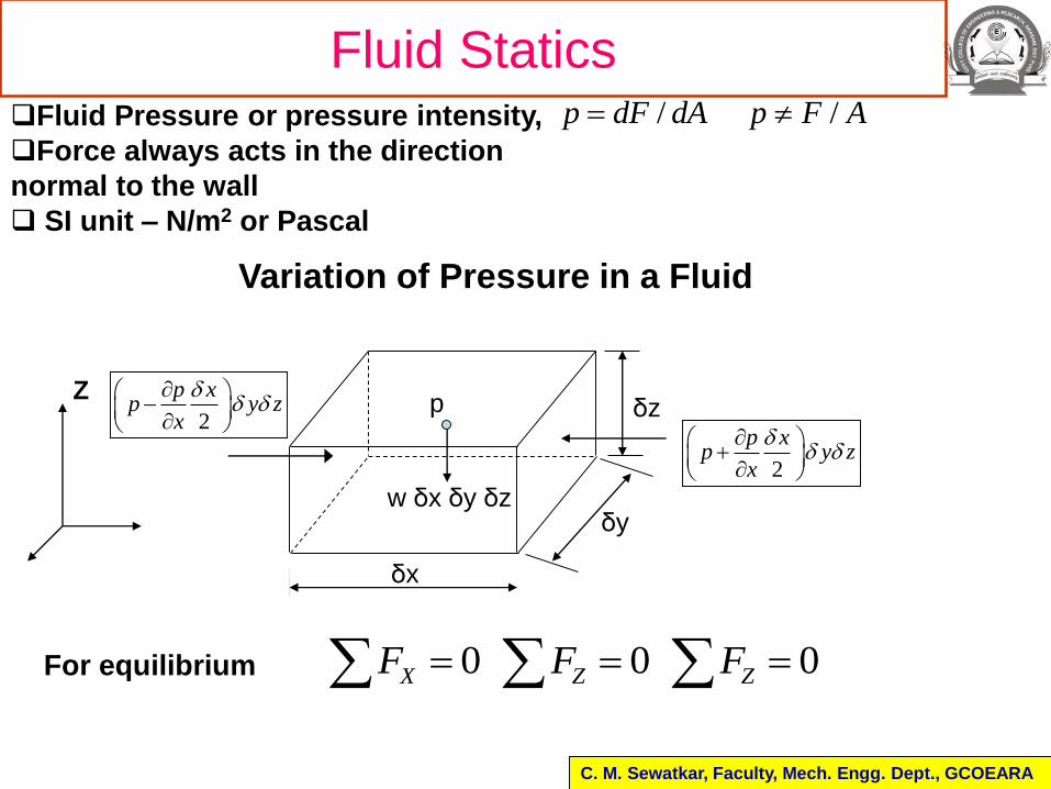
Fluid StaticsFluid Pressure or pressure intensity,
Force always acts in the direction
normal to the wall
SI unit – N/m2 or Pascal
/p dF dA /p F A
Variation of Pressure in a Fluid
δx
δz
w δx δy δz
p
X
Z
Y
2
p xp y z
x
2
p xp y z
x
C. M. Sewatkar, Faculty, Mech. Engg. Dept., GCOEARA
δy
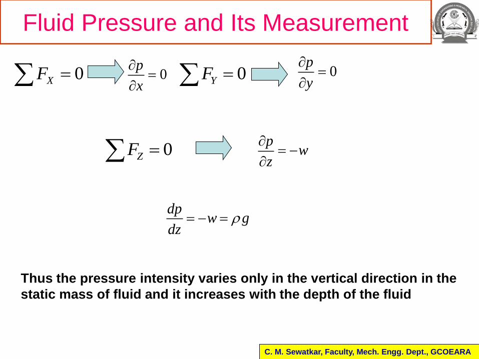
For equilibrium 0 0 0 X Z ZF F F
Fluid Pressure and Its Measurement
Y
C. M. Sewatkar, Faculty, Mech. Engg. Dept., GCOEARA
0p
x
0
p
y
pw
z
dpw g
dz
0XF 0YF
0ZF
Thus the pressure intensity varies only in the vertical direction in the
static mass of fluid and it increases with the depth of the fluid
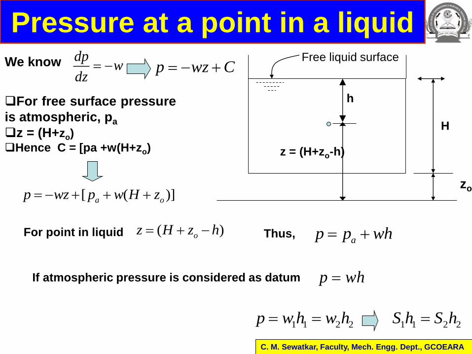
Pressure at a point in a liquidFree liquid surface
h
zo
z = (H+zo-h)
dpw
dz p wz C
For free surface pressure
is atmospheric, pa
z = (H+zo)
Hence C = [pa +w(H+zo)
We know
[ ( )]a op wz p w H z
For point in liquid ( )oz H z h Thus,ap p wh
If atmospheric pressure is considered as datum p wh
1 1 2 2p w h w h 1 1 2 2S h S h
C. M. Sewatkar, Faculty, Mech. Engg. Dept., GCOEARA
H
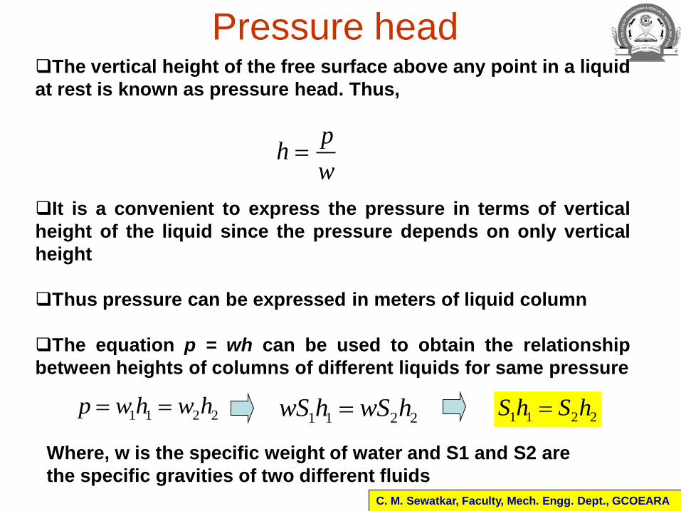
Pressure headThe vertical height of the free surface above any point in a liquid
at rest is known as pressure head. Thus,
ph
w
C. M. Sewatkar, Faculty, Mech. Engg. Dept., GCOEARA
It is a convenient to express the pressure in terms of vertical
height of the liquid since the pressure depends on only vertical
height
Thus pressure can be expressed in meters of liquid column
The equation p = wh can be used to obtain the relationship
between heights of columns of different liquids for same pressure
1 1 2 2p w h w h 1 1 2 2S h S h
1 1 2 2wS h wS h
Where, w is the specific weight of water and S1 and S2 are
the specific gravities of two different fluids
Pascal’s Law
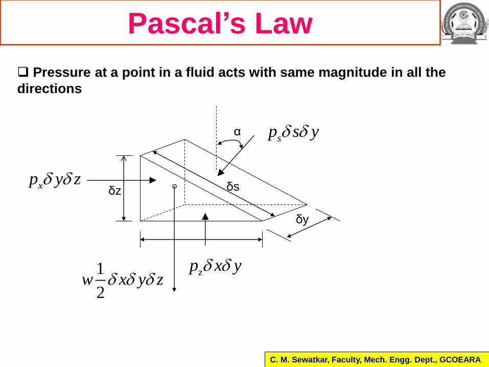
Pressure at a point in a fluid acts with same magnitude in all the
directions
δx
δy
δz δs
α
xp y z
zp x y
sp s y
1
2w x y z
C. M. Sewatkar, Faculty, Mech. Engg. Dept., GCOEARA
Pascal’s Law
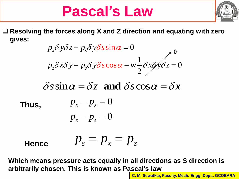
s x zp p p
Resolving the forces along X and Z direction and equating with zero
gives:
Which means pressure acts equally in all directions as S direction is
arbitrarily chosen. This is known as Pascal’s law
sin
cos
0
10
2
x s
z s
p y z p y
p x y p x y z
s
sy w
sin cos and s z s x
0
Thus, 0
0
x s
z s
p p
p p
Hence
C. M. Sewatkar, Faculty, Mech. Engg. Dept., GCOEARA
Atmospheric, absolute, gage and vacuum
pressure
C. M. Sewatkar, Faculty, Mech. Engg. Dept., GCOEARA
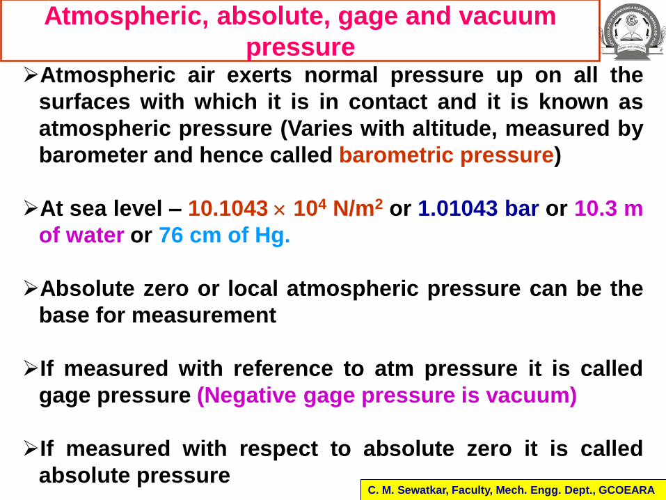
Atmospheric air exerts normal pressure up on all the
surfaces with which it is in contact and it is known as
atmospheric pressure (Varies with altitude, measured by
barometer and hence called barometric pressure)
At sea level – 10.1043 104 N/m2 or 1.01043 bar or 10.3 m
of water or 76 cm of Hg.
Absolute zero or local atmospheric pressure can be the
base for measurement
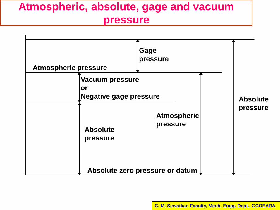
If measured with reference to atm pressure it is called
gage pressure (Negative gage pressure is vacuum)
If measured with respect to absolute zero it is called
absolute pressure
Atmospheric, absolute, gage and vacuum
pressure
C. M. Sewatkar, Faculty, Mech. Engg. Dept., GCOEARA
Absolute
pressure
Atmospheric pressure
Gage
pressure
Atmospheric
pressureAbsolute
pressure
Vacuum pressure
or
Negative gage pressure
Absolute zero pressure or datum
Pressure Measurement
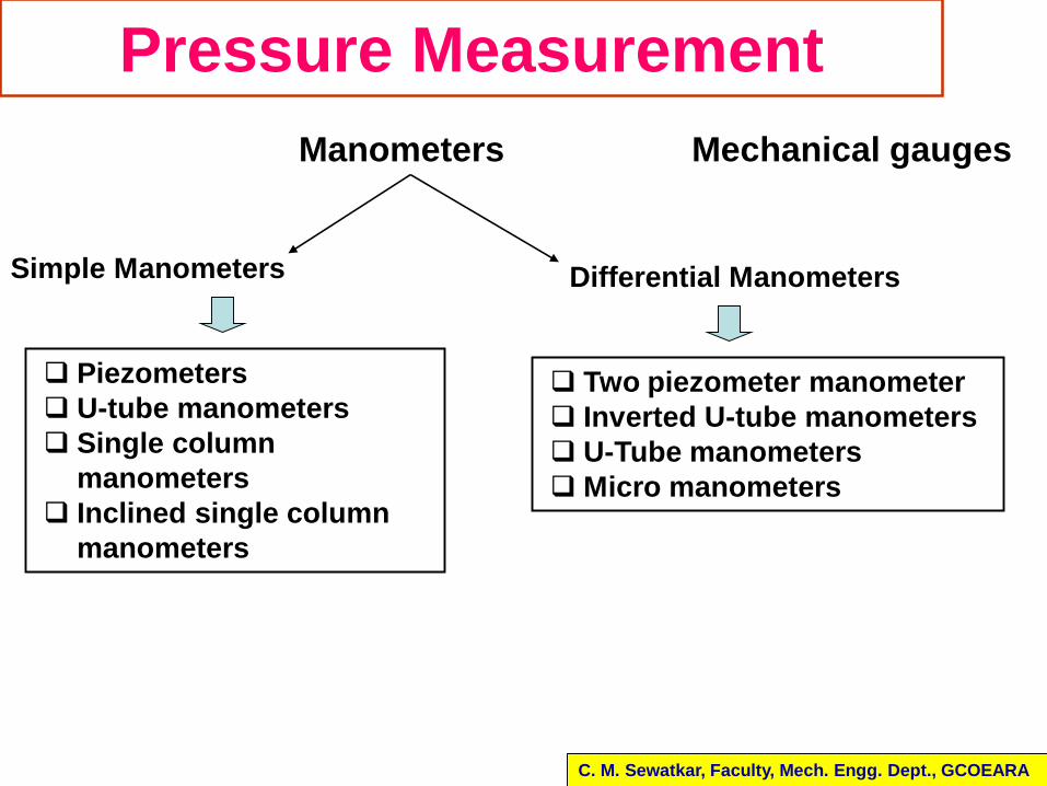
Manometers Mechanical gauges
Simple Manometers Differential Manometers
Piezometers
U-tube manometers
Single column
manometers
Inclined single column
manometers
C. M. Sewatkar, Faculty, Mech. Engg. Dept., GCOEARA
Two piezometer manometer
Inverted U-tube manometers
U-Tube manometers
Micro manometers
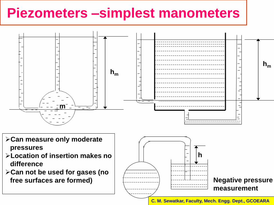
Piezometers –simplest manometers
C. M. Sewatkar, Faculty, Mech. Engg. Dept., GCOEARA
h
Negative pressure
measurement
hm
m
hm
Can measure only moderate
pressures
Location of insertion makes no
difference
Can not be used for gases (no
free surfaces are formed)
U-Tube manometers
Fluid of sp.
Gr. S1
y
z
A
Manometric fluid
(Sp. Gr. S2) A glass U-tube with heavier
manometric fluid is used
Procedure to write manometric
expression
Start from A or free surface and
write pressure there in appropriate
unit (N/m2 or m of H2O)
Add the change in pressure
caused due to change from one
level to adjacent level.
Use +ve if the adjacent level is
lower.
Use –ve sign if it is higher.
Continue till other end and equate
with pressure at that point
C. M. Sewatkar, Faculty, Mech. Engg. Dept., GCOEARA
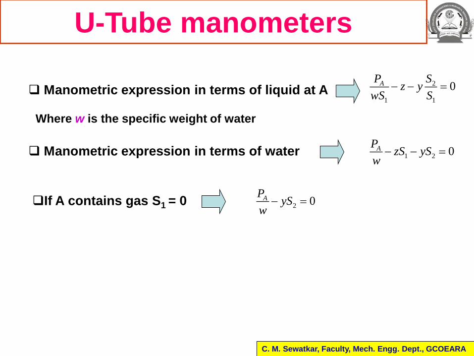
Manometric expression in terms of liquid at A2
1 1
0AP Sz y
wS S
Manometric expression in terms of water 1 2 0APzS yS
w
U-Tube manometers
C. M. Sewatkar, Faculty, Mech. Engg. Dept., GCOEARA
Where w is the specific weight of water
If A contains gas S1 = 0 2 0APyS
w
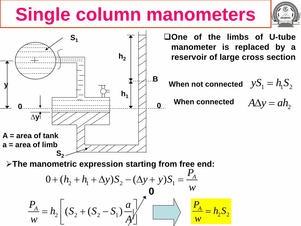
Single column manometers
0 0
yB
h1
h2
One of the limbs of U-tube
manometer is replaced by a
reservoir of large cross section
∆y
S1
S2
When not connected 1 1 2yS h S
When connected2A y ah
A = area of tank
a = area of limb
The manometric expression starting from free end:
2 1 2 10 ( ) ( ) APh h y S y y S
w
2 2 2 1( ( )AP ah S S S
w A
0
2 2AP
h Sw
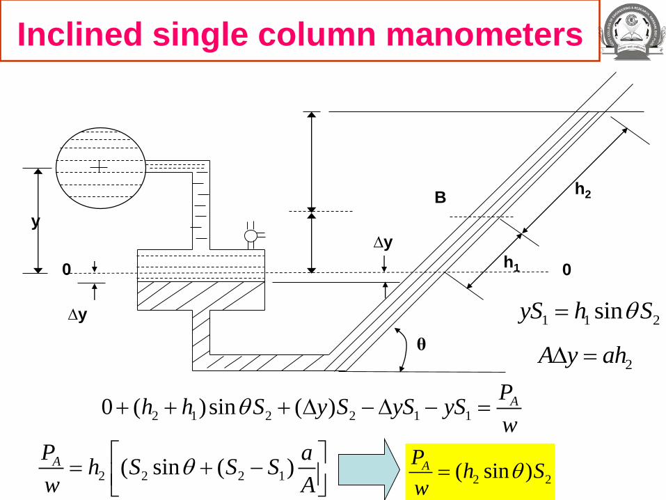
Inclined single column manometers
0 0
y
B
h1
h2
∆y
θ
1 1 2sinyS h S
2A y ah
2 1 2 2 1 10 ( )sin ( ) APh h S y S yS yS
w
∆y
2 2 2 1( sin ( )AP ah S S S
w A
2 2( sin )AP
h Sw
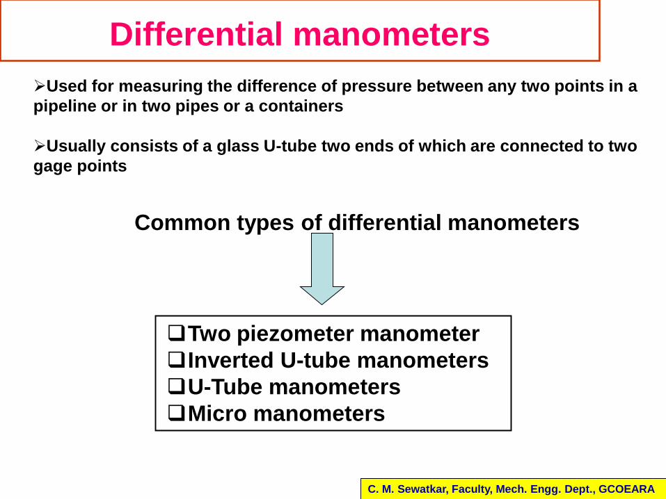
Differential manometers
Used for measuring the difference of pressure between any two points in a
pipeline or in two pipes or a containers
Usually consists of a glass U-tube two ends of which are connected to two
gage points
Two piezometer manometer
Inverted U-tube manometers
U-Tube manometers
Micro manometers
Common types of differential manometers
C. M. Sewatkar, Faculty, Mech. Engg. Dept., GCOEARA
h
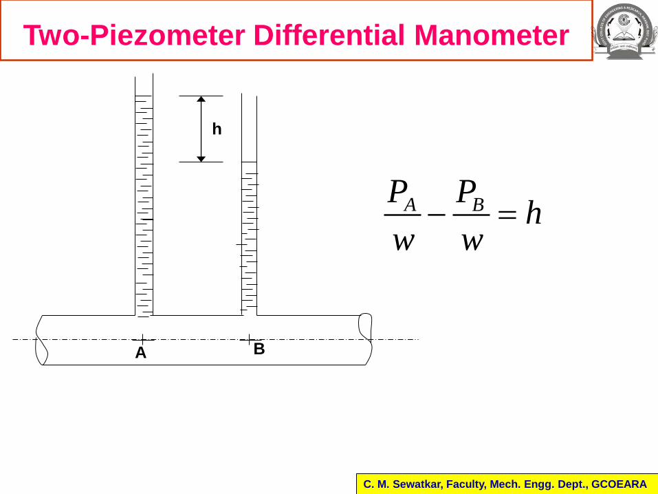
Two-Piezometer Differential Manometer
A B
A BP Ph
w w
C. M. Sewatkar, Faculty, Mech. Engg. Dept., GCOEARA
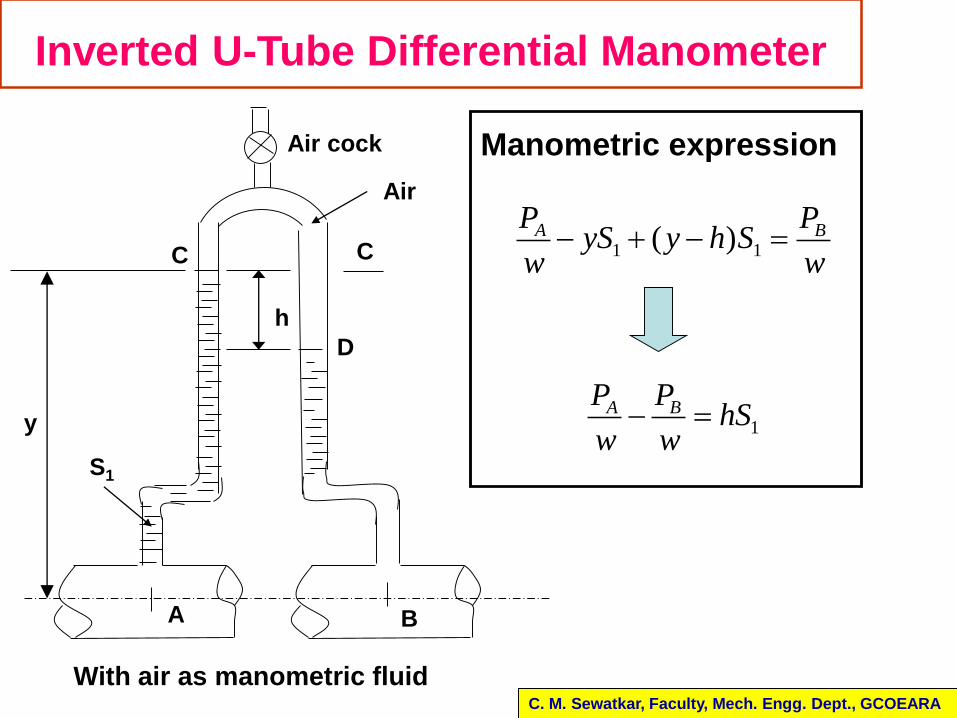
Inverted U-Tube Differential Manometer
C. M. Sewatkar, Faculty, Mech. Engg. Dept., GCOEARA
Manometric expression
1 1( )A BP PyS y h S
w w
1A BP P
hSw w
h
Air cock
B
y
Air
C C
With air as manometric fluid
A
S1
D
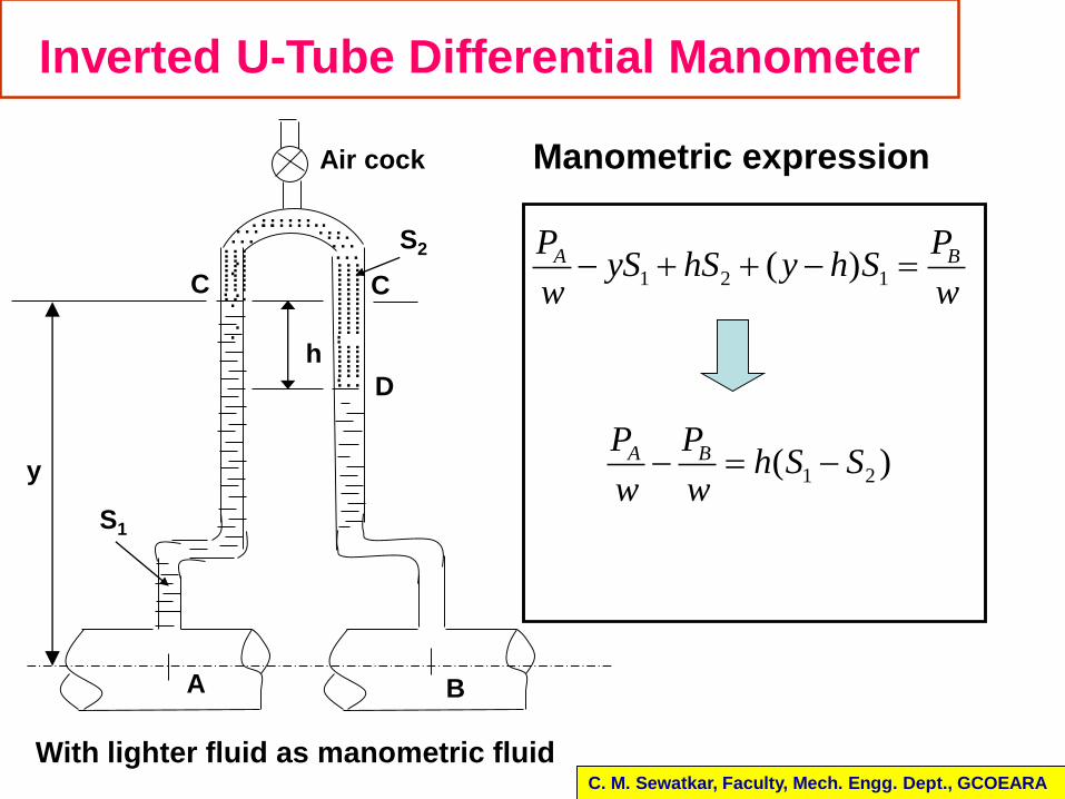
Inverted U-Tube Differential Manometer
C. M. Sewatkar, Faculty, Mech. Engg. Dept., GCOEARA
Manometric expression
1 2 1( )A BP PyS hS y h S
w w
1 2( )A BP Ph S S
w w
With lighter fluid as manometric fluid
h
Air cock
……………………….…
………………………………………..………………….…
…………..…
.
.
.
…
.
.
.
…
…………
y
A B
S2
S1
C C
D
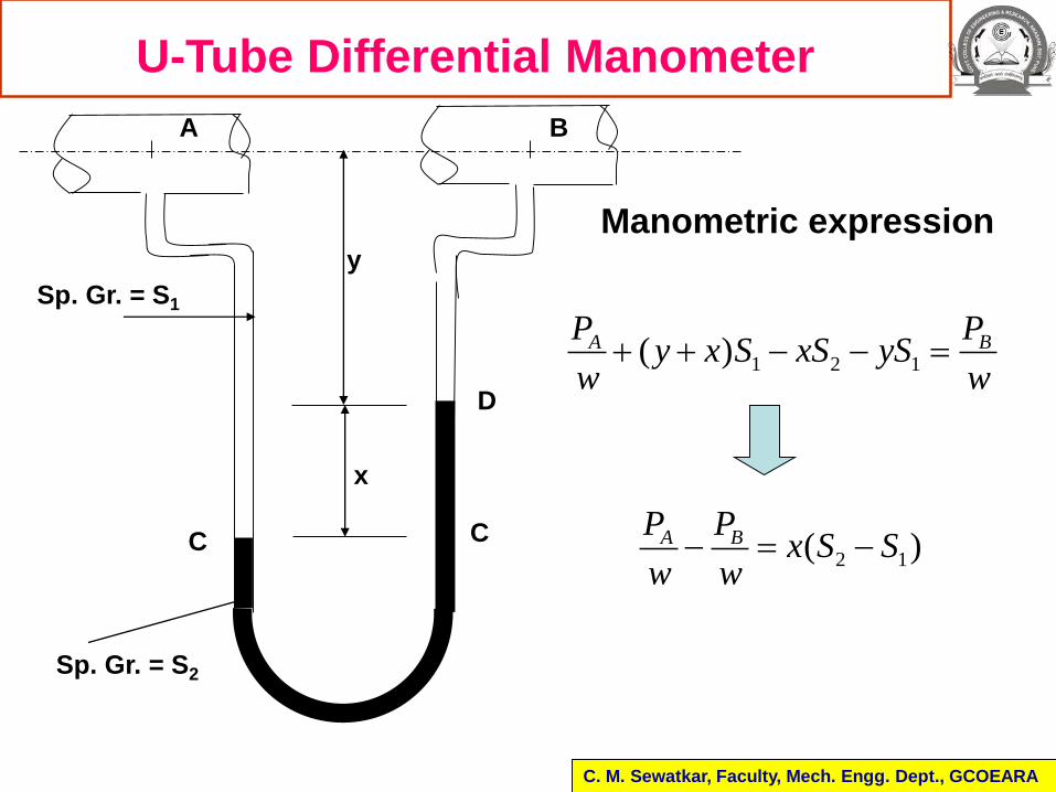
U-Tube Differential Manometer
C. M. Sewatkar, Faculty, Mech. Engg. Dept., GCOEARA
1 2 1( )A BP Py x S xS yS
w w
2 1( )A BP Px S S
w w
Manometric expression
x
y
A B
C C
Sp. Gr. = S2
D
Sp. Gr. = S1
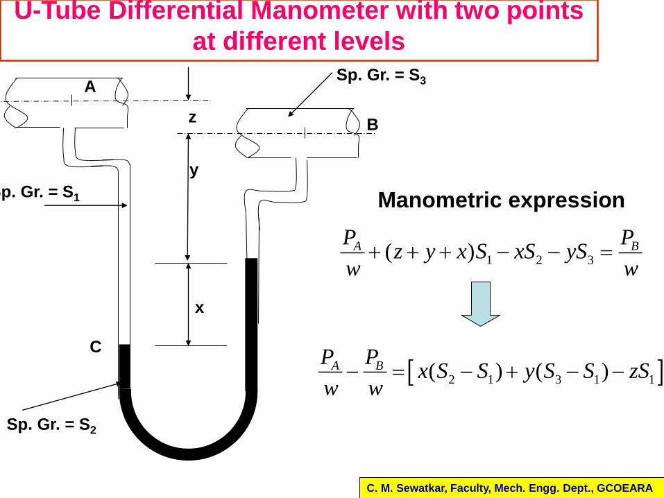
U-Tube Differential Manometer with two points
at different levels
C. M. Sewatkar, Faculty, Mech. Engg. Dept., GCOEARA
B
x
y
C
Sp. Gr. = S2
Sp. Gr. = S1
z
ASp. Gr. = S3
1 2 3( )A BP Pz y x S xS yS
w w
2 1 3 1 1( ) ( )A BP Px S S y S S zS
w w
Manometric expression
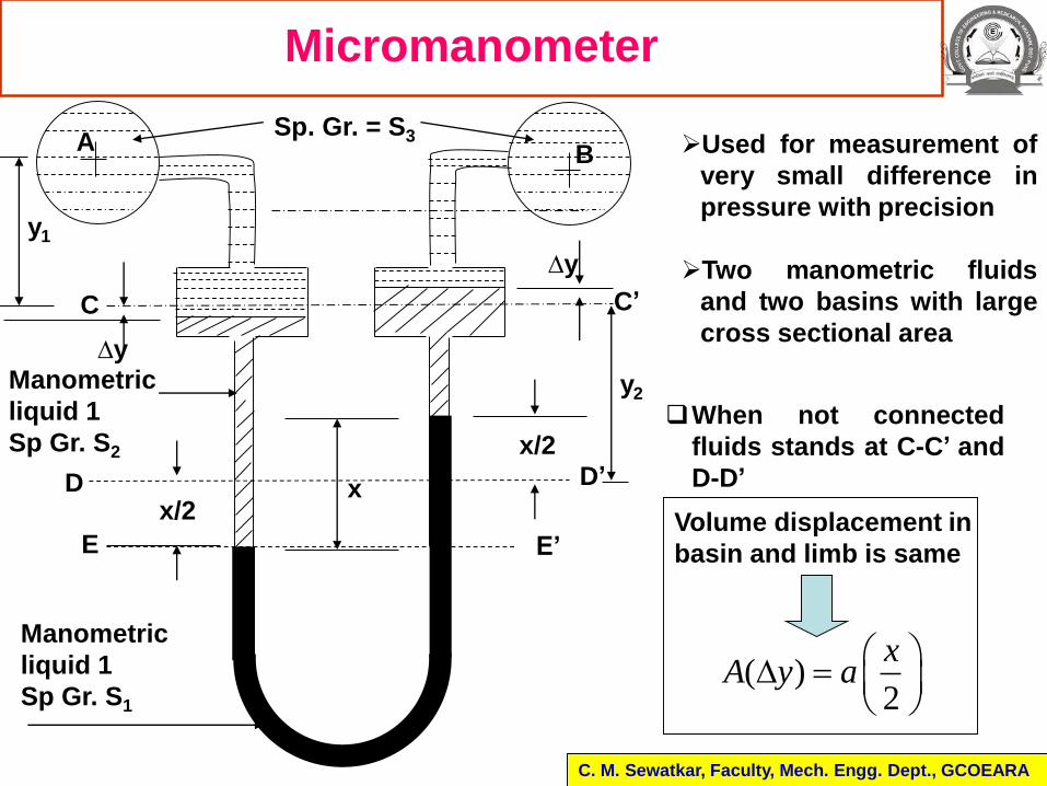
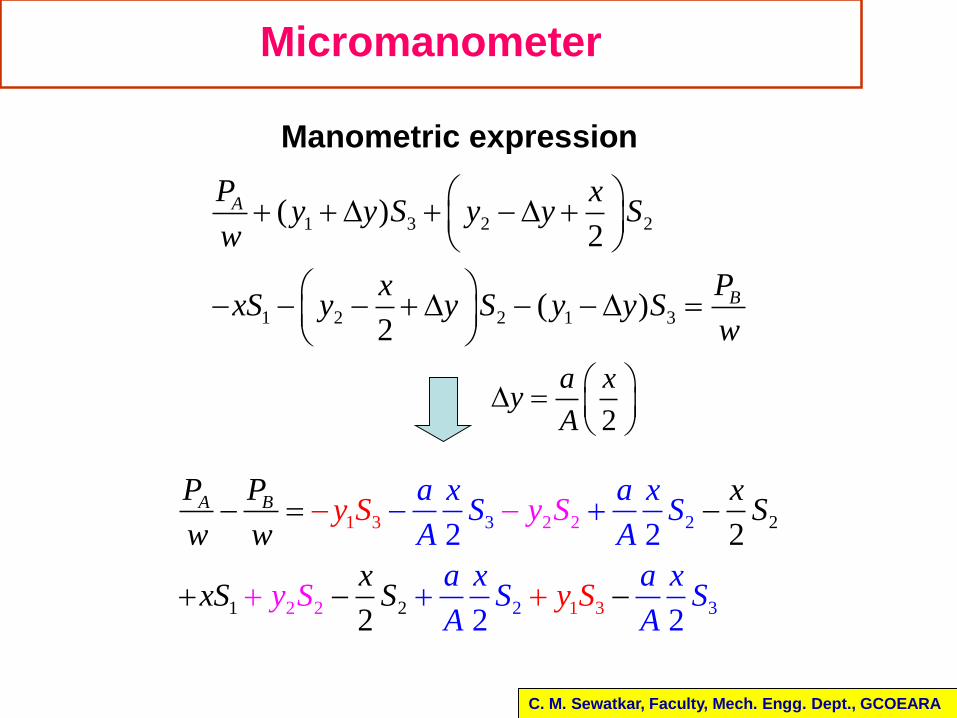
Micromanometer
C. M. Sewatkar, Faculty, Mech. Engg. Dept., GCOEARA
Used for measurement of
very small difference in
pressure with precision
Two manometric fluids
and two basins with large
cross sectional area
Manometric
liquid 1
Sp Gr. S2
xx/2
x/2
Sp. Gr. = S3
y1
∆y
∆y
Manometric
liquid 1
Sp Gr. S1
BA
C C’
D’D
E E’
( )2
xA y a
Volume displacement in
basin and limb is same
When not connected
fluids stands at C-C’ and
D-D’
y2
Micromanometer
C. M. Sewatkar, Faculty, Mech. Engg. Dept., GCOEARA
1 3 2 2
1 2 2 1 3
( )2
( )2
A
B
P xy y S y y S
w
PxxS y y S y y S
w
Manometric expression
2
a xy
A
3 2
2 3
1 2 2
1 2
2
2
3
1 32
2
2
2 2
2 2
A BP P xSy S
y
a x a xS S
Aw w
x
A
xS S
y S
y Sa a
Sx x
S SA A
1 2A BP P
x S Sw w
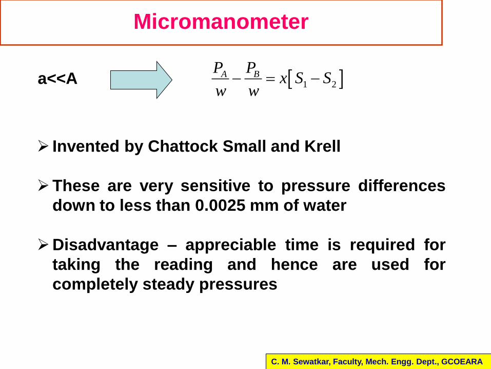
Micromanometer
C. M. Sewatkar, Faculty, Mech. Engg. Dept., GCOEARA
a<<A
Invented by Chattock Small and Krell
These are very sensitive to pressure differences
down to less than 0.0025 mm of water
Disadvantage – appreciable time is required for
taking the reading and hence are used for
completely steady pressures
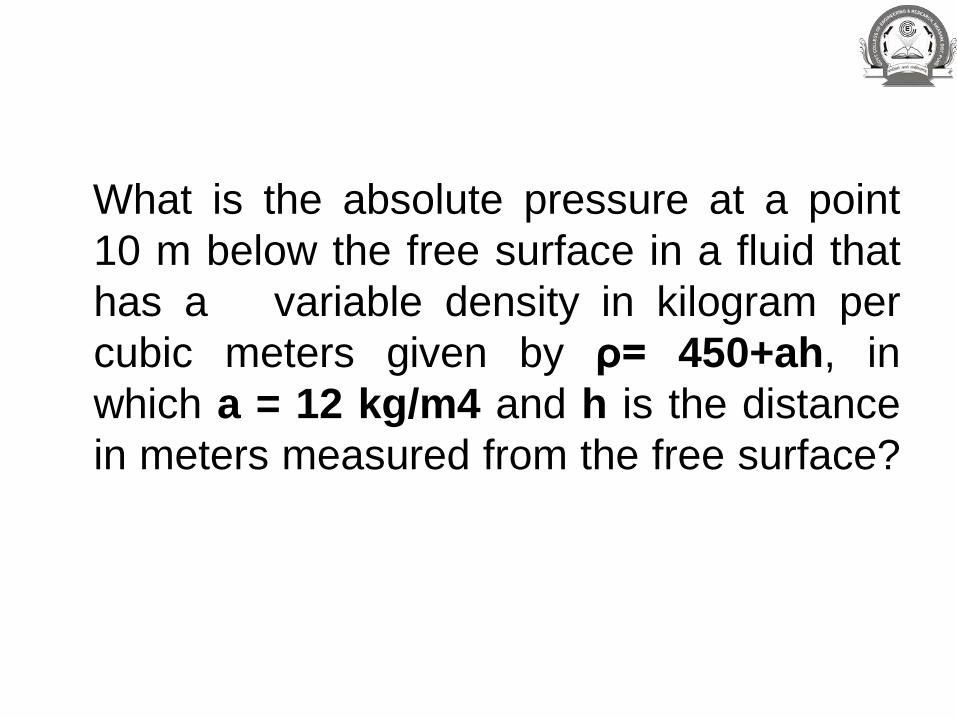
What is the absolute pressure at a point
10 m below the free surface in a fluid that
has a variable density in kilogram per
cubic meters given by ρ= 450+ah, in
which a = 12 kg/m4 and h is the distance
in meters measured from the free surface?
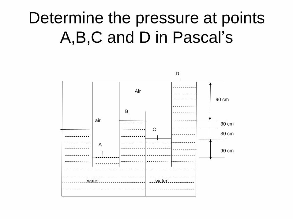
Determine the pressure at points
A,B,C and D in Pascal’s
waterwater
D
C
B
A
air
Air
90 cm
30 cm
90 cm
30 cm
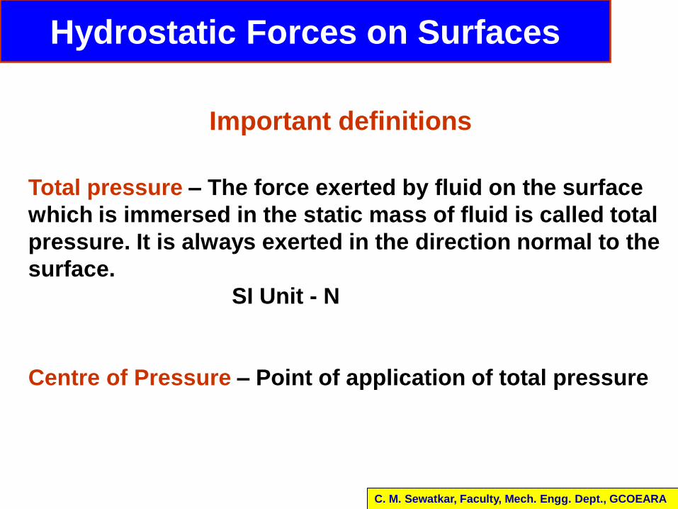
Hydrostatic Forces on Surfaces
Total pressure – The force exerted by fluid on the surface
which is immersed in the static mass of fluid is called total
pressure. It is always exerted in the direction normal to the
surface.
SI Unit - N
Centre of Pressure – Point of application of total pressure
Vertical surface
Important definitions
C. M. Sewatkar, Faculty, Mech. Engg. Dept., GCOEARA
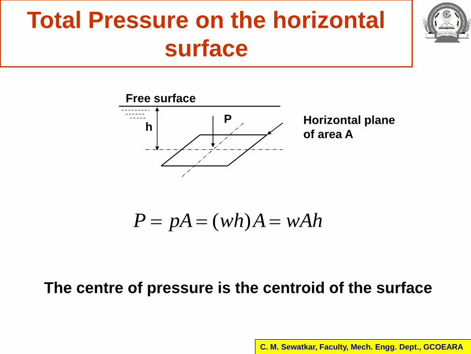
Total Pressure on the horizontal
surface
hP Horizontal plane
of area A
( )P pA wh A wAh
Free surface
C. M. Sewatkar, Faculty, Mech. Engg. Dept., GCOEARA
The centre of pressure is the centroid of the surface
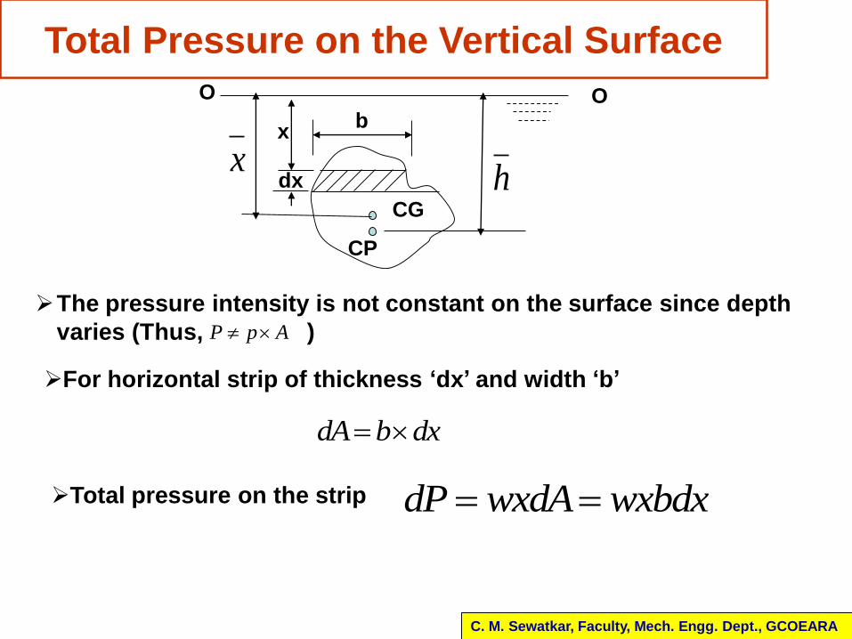
Total Pressure on the Vertical Surface
The pressure intensity is not constant on the surface since depth
varies (Thus, )P p A
For horizontal strip of thickness ‘dx’ and width ‘b’
dA b dx
Total pressure on the strip dP wxdA wxbdx
C. M. Sewatkar, Faculty, Mech. Engg. Dept., GCOEARA
x
CG
CP
h
x
dx
b
O O
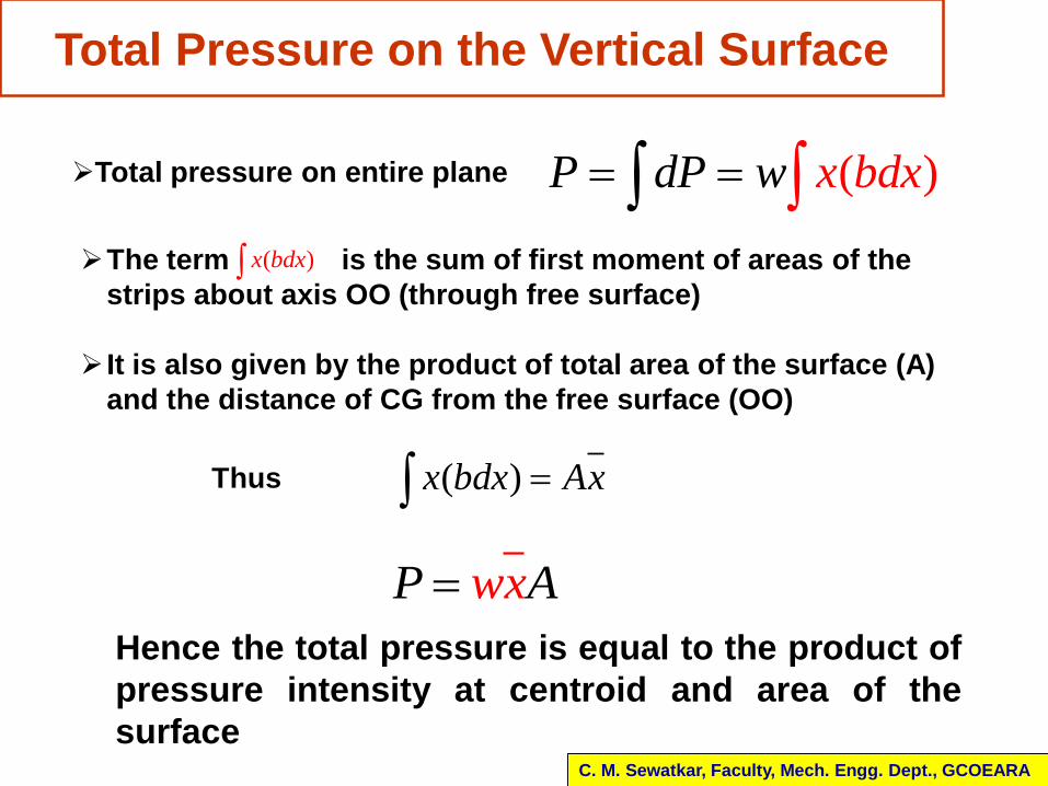
Total Pressure on the Vertical Surface
Total pressure on entire plane ( )xP d bw dP x The term is the sum of first moment of areas of the
strips about axis OO (through free surface)
It is also given by the product of total area of the surface (A)
and the distance of CG from the free surface (OO)
( )x bdx
( )x bdx AxThus
P Awx
Hence the total pressure is equal to the product of
pressure intensity at centroid and area of the
surfaceC. M. Sewatkar, Faculty, Mech. Engg. Dept., GCOEARA
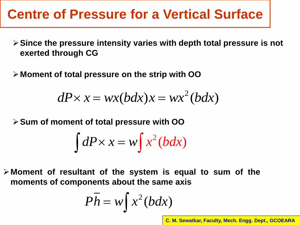
Centre of Pressure for a Vertical Surface
Vertical surface
Since the pressure intensity varies with depth total pressure is not
exerted through CG
Moment of total pressure on the strip with OO
2( ) ( )dP x wx bdx x wx bdx
Sum of moment of total pressure with OO
2 ( )x ddP x w b x
Moment of resultant of the system is equal to sum of the
moments of components about the same axis
2 ( )Ph w x bdx C. M. Sewatkar, Faculty, Mech. Engg. Dept., GCOEARA
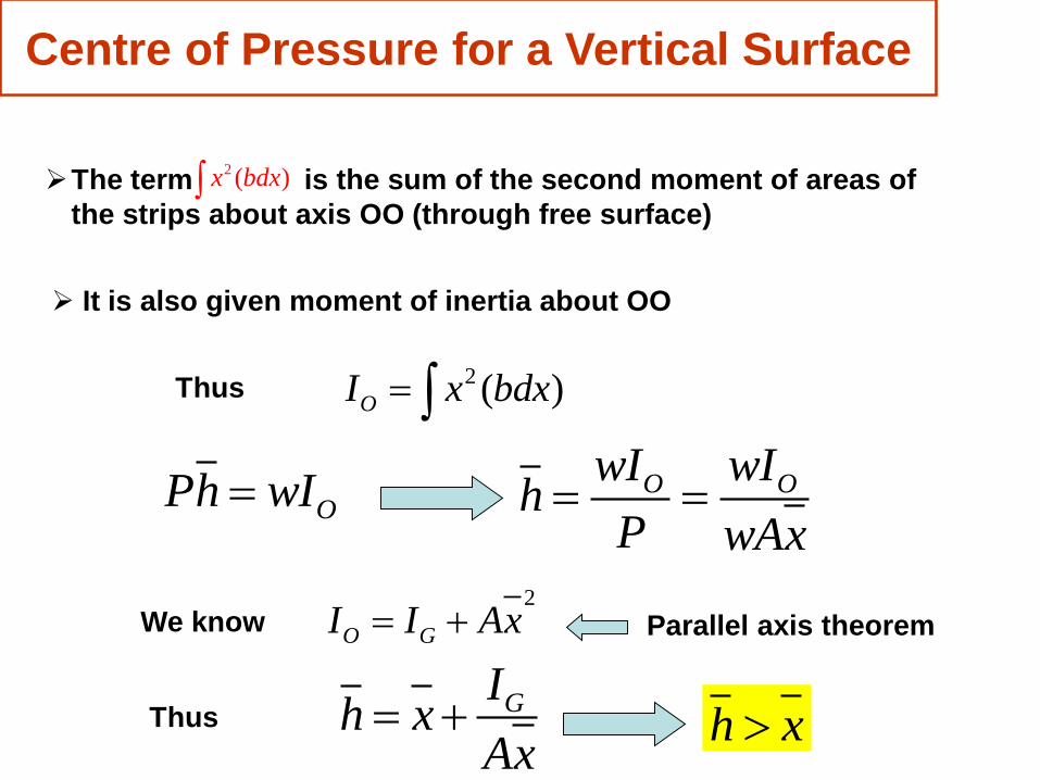
Centre of Pressure for a Vertical Surface
The term is the sum of the second moment of areas of
the strips about axis OO (through free surface)
2 ( )x bdx
It is also given moment of inertia about OO
2 ( )OI x bdx Thus
OPh wI O OwI wIh
P wAx
2
O GI I Ax We know Parallel axis theorem
ThusGIh x
Ax h x
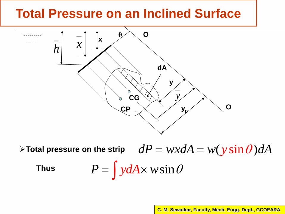
Total Pressure on an Inclined Surface
CG
CP
xhx
θ
dA
y
yp
Total pressure on the strip ( s )indP wx AydA w d
y
Thus sinydAP w
C. M. Sewatkar, Faculty, Mech. Engg. Dept., GCOEARA
O
O
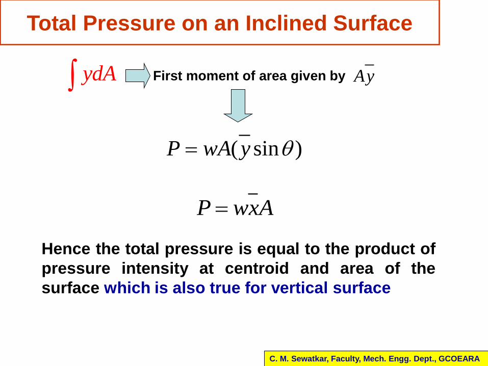
ydA First moment of area given by Ay
( sin )P wA y
Total Pressure on an Inclined Surface
P wxA
Hence the total pressure is equal to the product of
pressure intensity at centroid and area of the
surface which is also true for vertical surface
C. M. Sewatkar, Faculty, Mech. Engg. Dept., GCOEARA
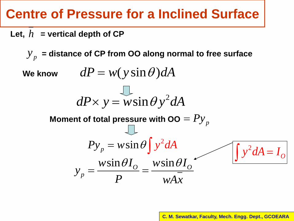
Centre of Pressure for a Inclined Surface
Let, = vertical depth of CP
= distance of CP from OO along normal to free surface
h
py
( sin )dP w y dAWe know
2sindP y w y dA
Moment of total pressure with OO pPy
2sinp y dP Ay w sin sinO O
p
w I w Iy
P wAx
2
Oy dA I
C. M. Sewatkar, Faculty, Mech. Engg. Dept., GCOEARA
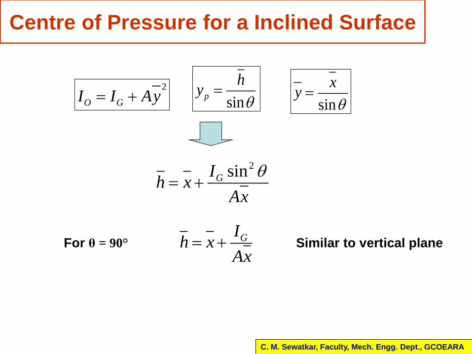
GIh xAx
2sinGIh xAx
2
O GI I Ay sinp
hy
sin
xy
Centre of Pressure for a Inclined Surface
For θ = 90° Similar to vertical plane
C. M. Sewatkar, Faculty, Mech. Engg. Dept., GCOEARA
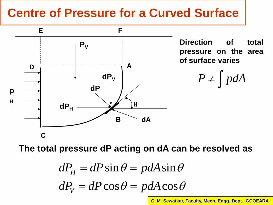
Centre of Pressure for a Curved Surface
C. M. Sewatkar, Faculty, Mech. Engg. Dept., GCOEARA
P pdA
Direction of total
pressure on the area
of surface varies
sin sin
cos cos
H
V
dP dP pdA
dP dP pdA
The total pressure dP acting on dA can be resolved as
A
C
B
E
D
F
θ
dP
dPH
dPV
PV
PH
dA
sin
cos
H H
V V
P dP w h
P dP w h
dA
dA
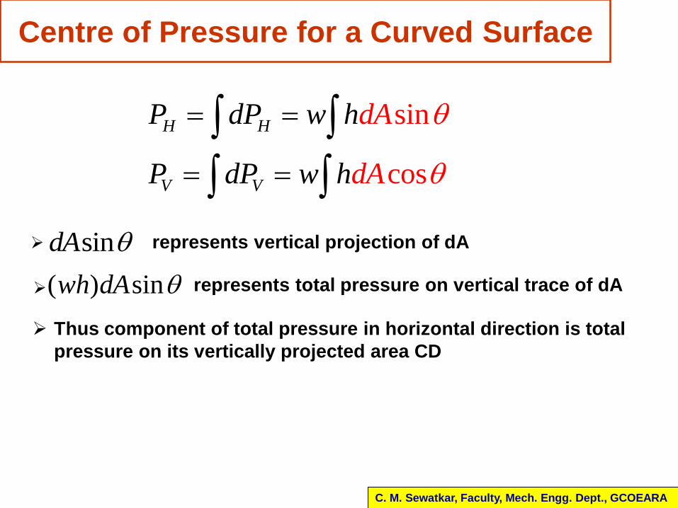
Centre of Pressure for a Curved Surface
C. M. Sewatkar, Faculty, Mech. Engg. Dept., GCOEARA
sindA represents vertical projection of dA
( ) sinwh dA represents total pressure on vertical trace of dA
Thus component of total pressure in horizontal direction is total
pressure on its vertically projected area CD
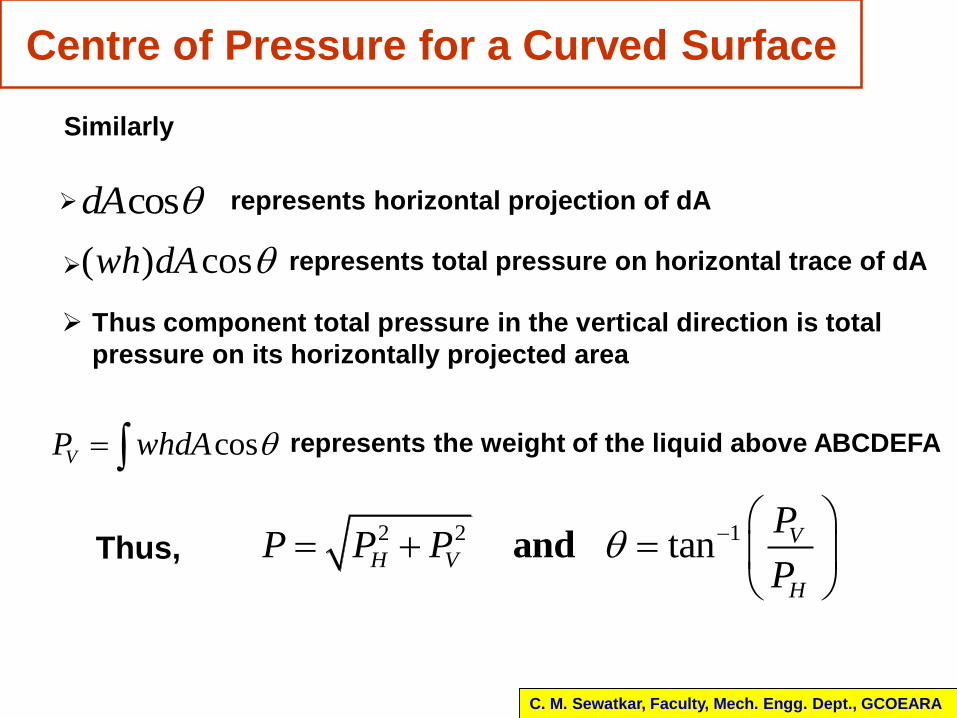
cosdA represents horizontal projection of dA
( ) coswh dA represents total pressure on horizontal trace of dA
Thus component total pressure in the vertical direction is total
pressure on its horizontally projected area
Centre of Pressure for a Curved Surface
C. M. Sewatkar, Faculty, Mech. Engg. Dept., GCOEARA
Similarly
cosVP whdA represents the weight of the liquid above ABCDEFA
2 2 1tan and VH V
H
PP P P
P
Thus,

Practical applications - Dams
C. M. Sewatkar, Faculty, Mech. Engg. Dept., GCOEARA
H
2/3(H)
H/3
( 1)2
Total Pressure per unit length of dam,
H
P wAx w H
2
2
wHP
311
12
2 ( 1) / 2
2
3
Centre of Pressure
GIh xAx
HH
hH H
h H
Practical applications - Gates
C. M. Sewatkar, Faculty, Mech. Engg. Dept., GCOEARA
H1
11 1
22 2
( / 2)
( / 2)
Total Pressure per unit length of dam,
P wAx wA H h
P wAx wA H h
1 2P P P P1
P2
H2
h
Resultant force experienced
by the gate
Buoyancy and Floatation
C. M. Sewatkar, Faculty, Mech. Engg. Dept., GCOEARA
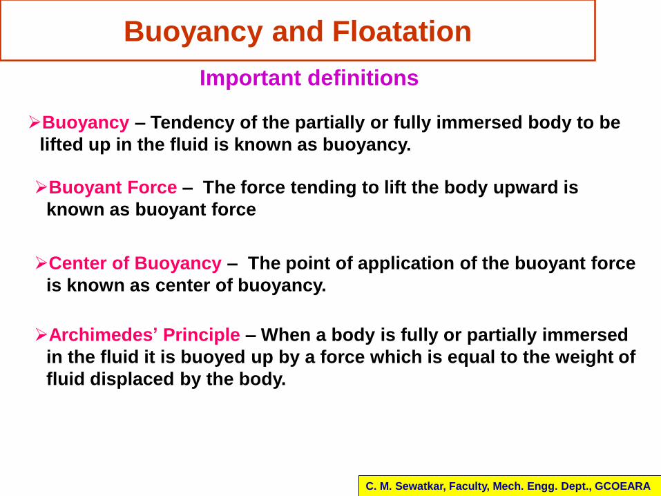
Important definitions
Buoyancy – Tendency of the partially or fully immersed body to be
lifted up in the fluid is known as buoyancy.
Buoyant Force – The force tending to lift the body upward is
known as buoyant force
Center of Buoyancy – The point of application of the buoyant force
is known as center of buoyancy.
Archimedes’ Principle – When a body is fully or partially immersed
in the fluid it is buoyed up by a force which is equal to the weight of
fluid displaced by the body.
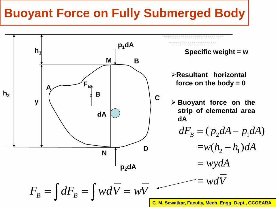
Buoyant Force on Fully Submerged Body
C. M. Sewatkar, Faculty, Mech. Engg. Dept., GCOEARA
h2
Specific weight = w
dA
p1dA
p2dA
M
N
y
h1
A
D
C
B
Resultant horizontal
force on the body = 0
Buoyant force on the
strip of elemental area
dA
2 1
2 1
( )
( ) =
=
BdF p dA p dA
w h h dA
wydA
wdV
B BF dF wdV wV
B
FB
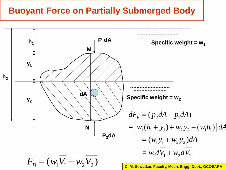
Buoyant Force on Partially Submerged Body
C. M. Sewatkar, Faculty, Mech. Engg. Dept., GCOEARA
dA
P1dA
P2dA
M
N
y1
h1
h2
Specific weight = w1
Specific weight = w2y2
2 1
1 1 1 2 2 1 1
1 1 2 2
1 1 2 2
( )
( ) ( )
( )
=
=
BdF p dA p dA
w h y w y w h dA
w y w y dA
w dV w dV
1 1 2 2( )BF wV w V
Specific weight = w
B
FB
G
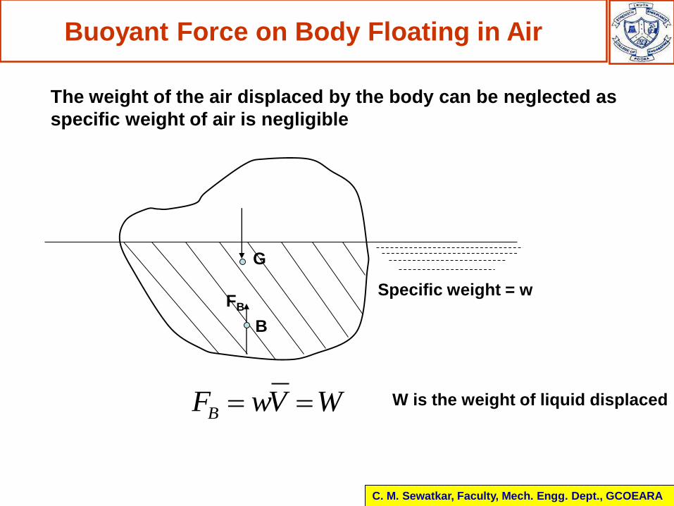
Buoyant Force on Body Floating in Air
C. M. Sewatkar, Faculty, Mech. Engg. Dept., GCOEARA
The weight of the air displaced by the body can be neglected as
specific weight of air is negligible
BF wV W W is the weight of liquid displaced
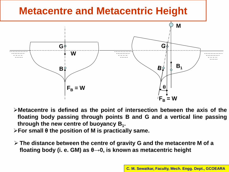
Metacentre and Metacentric Height
C. M. Sewatkar, Faculty, Mech. Engg. Dept., GCOEARA
Metacentre is defined as the point of intersection between the axis of the
floating body passing through points B and G and a vertical line passing
through the new centre of buoyancy B1.
For small θ the position of M is practically same.
The distance between the centre of gravity G and the metacentre M of a
floating body (i. e. GM) as θ→0, is known as metacentric height
G
W
B
FB = W
M
FB = W
θ
B1
Stability of Submerged and Floating Bodies
C. M. Sewatkar, Faculty, Mech. Engg. Dept., GCOEARA
Stability of submerged or floating body
- Tendency of the body to return to the original upright
position after it has been slightly displaced.
When a submerged or floating body is given a slight angular
displacement it may have either of the following three conditions
of equilibrium
Stable equilibrium
Unstable equilibrium
Neutral equilibrium
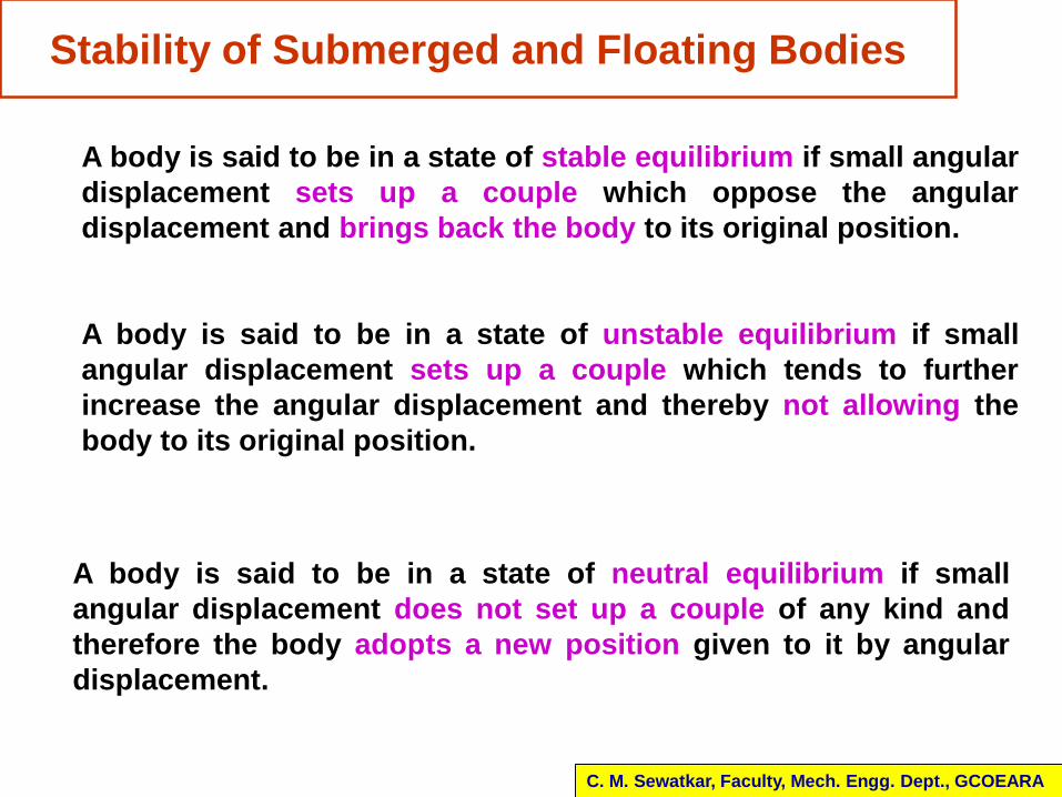
A body is said to be in a state of stable equilibrium if small angular
displacement sets up a couple which oppose the angular
displacement and brings back the body to its original position.
Stability of Submerged and Floating Bodies
C. M. Sewatkar, Faculty, Mech. Engg. Dept., GCOEARA
A body is said to be in a state of unstable equilibrium if small
angular displacement sets up a couple which tends to further
increase the angular displacement and thereby not allowing the
body to its original position.
A body is said to be in a state of neutral equilibrium if small
angular displacement does not set up a couple of any kind and
therefore the body adopts a new position given to it by angular
displacement.
B
FB=W
W
G
B
FB=W
W
G
C. M. Sewatkar, Faculty, Mech. Engg. Dept., GCOEARA
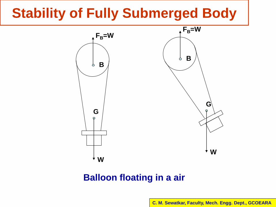
Stability of Fully Submerged Body
Balloon floating in a air
C. M. Sewatkar, Faculty, Mech. Engg. Dept., GCOEARA
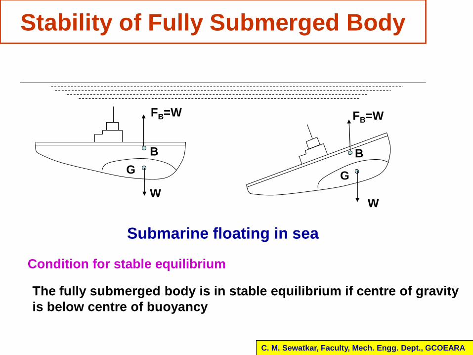
Stability of Fully Submerged Body
FB=W
W
G
B
G
W
FB=W
B
Submarine floating in sea
The fully submerged body is in stable equilibrium if centre of gravity
is below centre of buoyancy
Condition for stable equilibrium
C. M. Sewatkar, Faculty, Mech. Engg. Dept., GCOEARA
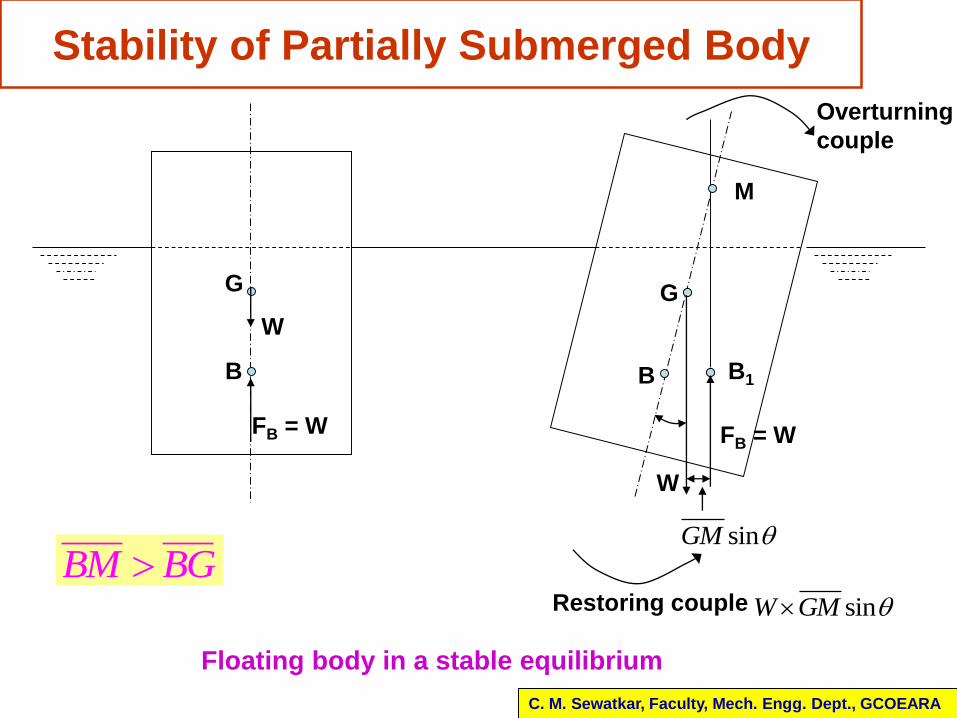
Stability of Partially Submerged Body
G
W
B
FB = W
B B1
M
sinGM
G
FB = W
W
Overturning
couple
Restoring couple sinW GM
Floating body in a stable equilibrium
BM BG
C. M. Sewatkar, Faculty, Mech. Engg. Dept., GCOEARA
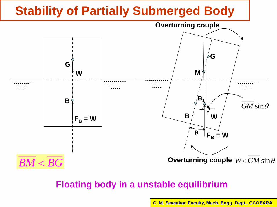
Stability of Partially Submerged Body
Floating body in a unstable equilibrium
G
W
B
FB = W B
B1
M
sinGM
G
FB = W
W
Overturning couple
Overturning couple sinW GM
θ
BM BG
C. M. Sewatkar, Faculty, Mech. Engg. Dept., GCOEARA
Importance of Stability of Floating Objects
Boats, ships etc are the important objects which are
subjected to external forces
Wind forces, wave forces, pressure due to tidal or river
currents, pressure due to maneuvering a boat or ship
in a curved path
Shifting of cargo may cause heeling
Movements of passengers also develops overturning
couple
Thus the care has to be taken in the design of boats or
ship so that metacentre is kept well above centre of
gravity
CG can be lowered by permanently loading the ship or
boat
C. M. Sewatkar, Faculty, Mech. Engg. Dept., GCOEARA
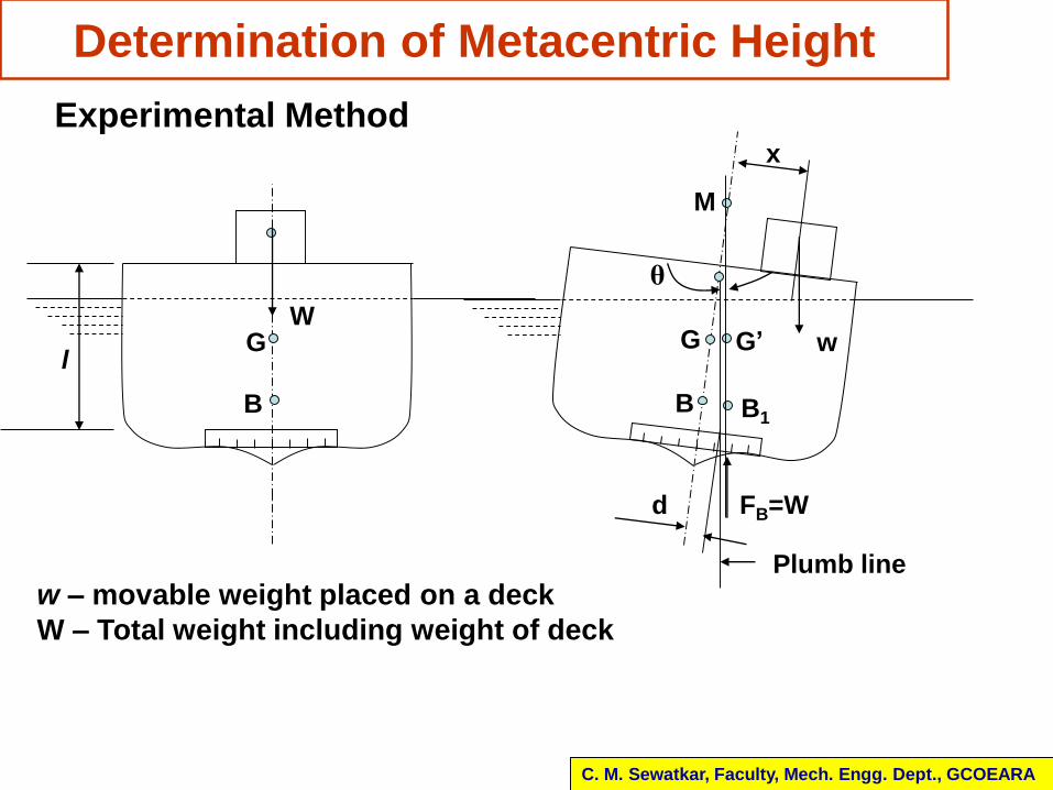
Determination of Metacentric Height
GW
B
l
Experimental Method
w – movable weight placed on a deck
W – Total weight including weight of deck
G
FB=W
B
w
B1
G’
M
x
Plumb line
d
θ
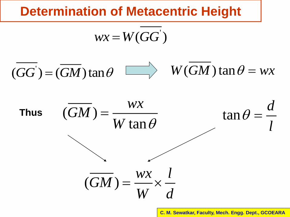
Determination of Metacentric Height
'( )wx W GG
'( ) ( ) tanGG GM ( ) tanW GM wx
( )tan
wxGM
W tan
d
l Thus
( )wx l
GMW d
C. M. Sewatkar, Faculty, Mech. Engg. Dept., GCOEARA
Determination of Metacentric Height
C. M. Sewatkar, Faculty, Mech. Engg. Dept., GCOEARA
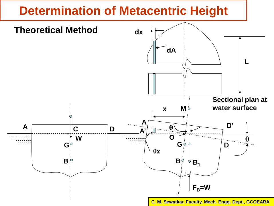
Theoretical Method
GW
B
G
FB=W
B B1
Mx
θA DCA
A’
D
D’
θ
dx
dA
Sectional plan at
water surface
θx
O
L
Determination of Metacentric Height
C. M. Sewatkar, Faculty, Mech. Engg. Dept., GCOEARA
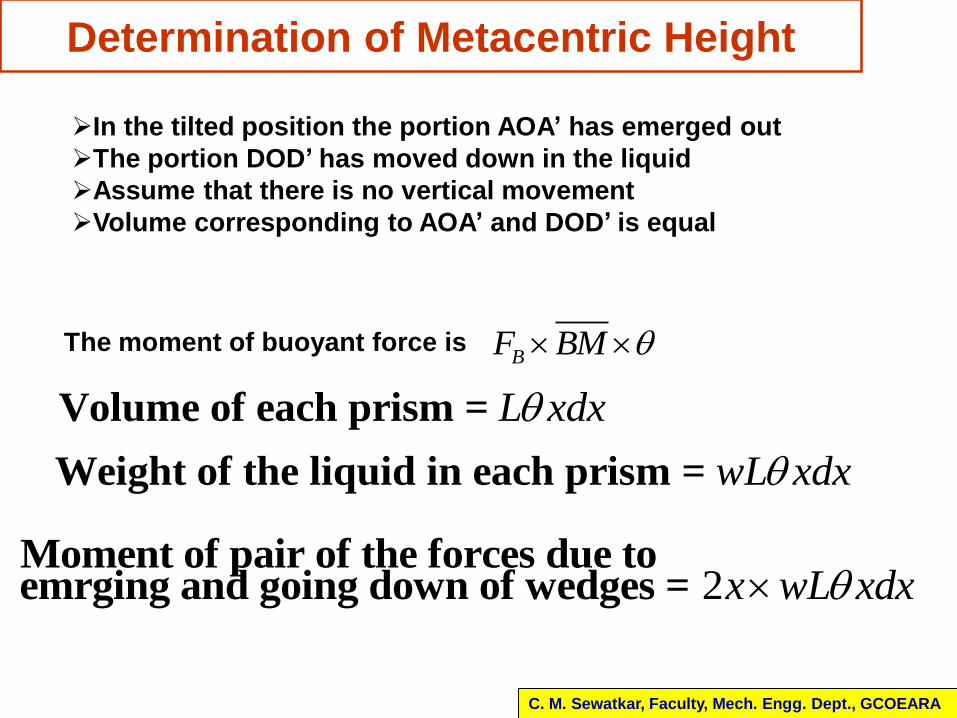
In the tilted position the portion AOA’ has emerged out
The portion DOD’ has moved down in the liquid
Assume that there is no vertical movement
Volume corresponding to AOA’ and DOD’ is equal
BF BM The moment of buoyant force is
Volume of each prism = L xdx
Weight of the liquid in each prism = wL xdx
2Moment of pair of the forces due to emrging and going down of wedges = x wL xdx
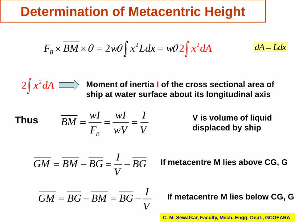
2 22 2B x dF BM w x Ld w Ax
Determination of Metacentric Height
C. M. Sewatkar, Faculty, Mech. Engg. Dept., GCOEARA
dA Ldx
22 x dA Moment of inertia I of the cross sectional area of
ship at water surface about its longitudinal axis
B
wI wI IBM
F wV V V is volume of liquid
displaced by shipThus
IGM BM BG BG
V If metacentre M lies above CG, G
IGM BG BM BG
V If metacentre M lies below CG, G
IGM BG
V
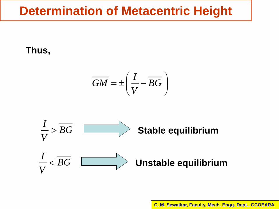
Determination of Metacentric Height
C. M. Sewatkar, Faculty, Mech. Engg. Dept., GCOEARA
Thus,
IBG
V Stable equilibrium
IBG
V Unstable equilibrium
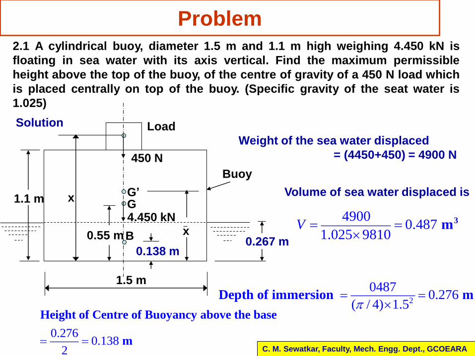
Problem
C. M. Sewatkar, Faculty, Mech. Engg. Dept., GCOEARA
2.1 A cylindrical buoy, diameter 1.5 m and 1.1 m high weighing 4.450 kN is
floating in sea water with its axis vertical. Find the maximum permissible
height above the top of the buoy, of the centre of gravity of a 450 N load which
is placed centrally on top of the buoy. (Specific gravity of the seat water is
1.025)
1.5 m
x
Load
Buoy
450 N
1.1 m
0.267 m
G’G
0.55 m
4.450 kNxB
0.138 m
Solution
Weight of the sea water displaced
= (4450+450) = 4900 N
Volume of sea water displaced is
49000.487
1.025 98103 mV
2
04870.276
( / 4) 1.5Depth of immersion m
0.2760.138
2
Height of Centre of Buoyancy above the base
m
Problem
C. M. Sewatkar, Faculty, Mech. Engg. Dept., GCOEARA
The position of combined centre of gravity of buoy and the load may be
obtained by taking moments total weight (acting at G’) about the base of the
buoy and equating it with the sum of moments of weight of buoy and weight
of load about base of the buoy
1.14900 4450 450
2x x Thus,
(0.499 0.092 )x x
The diagram suggests ' 'BG OG OB
0.138
(0.499 0.092 ) 0.138
(0.361 0.092 )
x
x
x
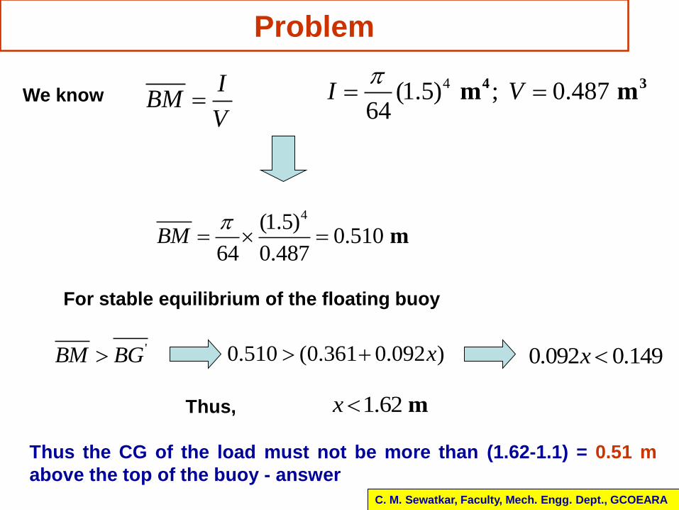
Problem
C. M. Sewatkar, Faculty, Mech. Engg. Dept., GCOEARA
4(1.5) ; 0.48764
4 3 m mI V
I
BMV
We know
4(1.5)0.510
64 0.487 mBM
For stable equilibrium of the floating buoy
'BM BG 0.510 (0.361 0.092 )x 0.092 0.149x
Thus, 1.62 mx
Thus the CG of the load must not be more than (1.62-1.1) = 0.51 m
above the top of the buoy - answer


![Fluid Mechanics - An-Najah National Universityvideos.najah.edu/sites/default/files/3--1.pdf · [3] Fall –2010 –Fluid Mechanics Dr. Mohammad N. Almasri [3-1] Fluid Statics Pressure](https://static.fdocuments.in/doc/165x107/5a8724087f8b9a14748d4e3e/fluid-mechanics-an-najah-national-3-fall-2010-fluid-mechanics-dr-mohammad.jpg)


![Fluid Mechanics - An-Najah Videos · [3] Fall –2010 –Fluid Mechanics Dr. Mohammad N. Almasri [3-1] Fluid Statics Fluid Pressure Fluid pressure is the normal force exerted by the](https://static.fdocuments.in/doc/165x107/5adc4efd7f8b9a8b6d8b62a3/fluid-mechanics-an-najah-videos-3-fall-2010-fluid-mechanics-dr-mohammad.jpg)