
Fluid Fuel Reactors - Chapter 6
39
CHAPTER 6 CHEMICALPROCESSING* 6-l .INTRODUCTION Oneofthepr nc paladvantagesofflu dfuelreactors stheposs b l tyof cont nuallyprocess ng thefuelandblanket mater alforthe removalof f ss onproductsand otherpo sonsandtherecoveryoff ss onablemater al produced . Suchcont nuous process ng accompl shes severaldes rable object ves :(a) mprovement oftheneutroneconomy suff c entlythatthe reactorbreedsmore f ss onablemater al than tconsumes, (b)m n m za- t onofthehazards assoc atedw ththe operat onofthereactor byma n- ta n ngalowconcentrat on ofrad oact vemater al nthefuel,and(c) m- provementofthel fe ofequ pmentandstab l tyofthefuelsolut on by remov ngdeleter ous f ss onandcorros on products . Theperformance andoperab l tyofahomogeneousreactorarecons derably moredependent ontheprocess ngcycle thanarethoseofasol d fuelreactor,although the object vesofprocess ng ares m lar . Theneutronpo son ng nahomogeneous reactorfromwh ch f ss on productgasesareremoved cont nuously slargelyduetorareearths [1], asshown nF g .6-1 . InF g . 6-1 therareearthscontr but ng toreactor po son ngared v ded ntotwogroups . Thet me-dependent rareearths arethoseofh gh y eldand ntermed ate crosssect on, suchasNd 143 andNd145Pr141 andPm 147 , wh choveraper odof severalmonthscould accumulate nthereactor andresult napo son ng ofabout207 0 . The constantrare-earthpo sonfract on sduepr mar lyto Sm 149 andS m ls1 , wh chhaveverylarge crosssect onsforneutron absorpt onbutlowy eld, andthereforereach the requ l br umlevel nonlyafewdays'operat on . Po son ngdueto corros onofthe sta nless-steelreactor systemwascal- culatedforatyp cal reactorconta n ng 15,500ft 2 ofsteelcorrod ng ata rateof1mpy . It sassumedthatonlythe n ckelandmanganesecontr bute tothepo son ng, s nce ronandchrom um w llhydrolyzeand prec p tate andberemovedfrom thereactorsystem ; otherw se,corros on product po son ngwouldbe fourt mesgreater than nd cated n Fg . 6-1 . The controlofrareearths andcorros onproduct elements sd scussed nsub- sequentsect onsof th schapter . Removalofsol dsfrom thefuelsolut on also mprovestheperformanceofthereactorbyd m n sh ng thedepos t on ofscaleonheat-transfer surfacesandreduc ng theposs b l tyoferos on of pump mpellers,bear ng surfaces,andvalve seats . *ByR .A .ItlcNees, w thcontr but ons fromW .E .Brown ng,W .D .Burch, R .E .Leuze,W .T .11cDuffee, andS .Peterson,Oak R dgeNat onalLaboratory .
-
Upload
the-e-generation -
Category
Documents
-
view
225 -
download
1
description
Chemical Processing
Transcript of Fluid Fuel Reactors - Chapter 6
CHAPTER 6
CHEMICAL PROCESSING*
6-l . INTRODUCTION
One of the principal advantages of fluid fuel reactors is the possibility ofcontinually processing the fuel and blanket material for the removal offission products and other poisons and the recovery of fissionable materialproduced . Such continuous processing accomplishes several desirableobjectives : (a) improvement of the neutron economy sufficiently that thereactor breeds more fissionable material than it consumes, (b) minimiza-tion of the hazards associated with the operation of the reactor by main-taining a low concentration of radioactive material in the fuel, and (c) im-provement of the life of equipment and stability of the fuel solution byremoving deleterious fission and corrosion products . The performanceand operability of a homogeneous reactor are considerably more dependenton the processing cycle than are those of a solid fuel reactor, although theobjectives of processing are similar .
The neutron poisoning in a homogeneous reactor from which fissionproduct gases are removed continuously is largely due to rare earths [1],as shown in Fig . 6-1 . In Fig . 6-1 the rare earths contributing to reactorpoisoning are divided into two groups . The time-dependent rare earthsare those of high yield and intermediate cross section, such as Nd143and N d145 Pr141 and Pm 147 , which over a period of several months couldaccumulate in the reactor and result in a poisoning of about 2070 . Theconstant rare-earth poison fraction is due primarily to Sm149 and Smls1 ,
which have very large cross sections for neutron absorption but low yield,and therefore reach their equilibrium level in only a few days' operation .Poisoning due to corrosion of the stainless-steel reactor system was cal-culated for a typical reactor containing 15,500 ft 2 of steel corroding at arate of 1 mpy . It is assumed that only the nickel and manganese contributeto the poisoning, since iron and chromium will hydrolyze and precipitateand be removed from the reactor system ; otherwise, corrosion productpoisoning would be four times greater than indicated in Fig . 6-1 . Thecontrol of rare earths and corrosion product elements is discussed in sub-sequent sections of this chapter . Removal of solids from the fuel solutionalso improves the performance of the reactor by diminishing the depositionof scale on heat-transfer surfaces and reducing the possibility of erosion ofpump impellers, bearing surfaces, and valve seats .
*By R. A. ItlcNees, with contributions from W. E. Browning, W. D. Burch,R. E. Leuze, W . T. 11cDuffee, and S. Peterson, Oak Ridge National Laboratory .

FIG. 6-1 . Poison effect as a function of chemical group in core of two-regionthermal breeder .
FIG. 6-2 . Conceptual flow diagram for processing fuel and blanket material froma two-region reactor .
The biological hazards associated with a homogeneous reactor are duechiefly to the radioactive rare earths, alkaline earths, and iodine [2] .The importance, as a biological hazard, of any one of these groups or nu-clides within the group depends on assumptions made in describing ex-posure conditions ; however, P 31 contributes a major fraction of the radia-tion hazards for any set of conditions . While the accumulation of hazardousmaterials such as rare earths and alkaline earths will be controlled by theprocessing methods to be described, less is known about the chemistry of

FiG. 6-3 . Conceptual flow diagram for processing blanket material from a two-region plutonium producer .
iodine in the fuel systems and methods for removing it . Existing informa-tion on iodine processing is discussed in Section 6-5 .
Schematic flowsheets for proposed processing schemes for two types oftwo-region aqueous homogeneous reactors are shown in Figs . 6-2 and 6-3 .In both cases, solids are removed by hydroclones and concentrated intoa small volume of solution for further processing . The nature of suchprocessing will be determined by the exact design and purpose of thereactor. Thus, for a two-region plutonium producer, the core and blanketmaterials would have to be processed separately to avoid isotopic dilution,while for a thorium breeder, core and blanket material could be processedtogether. However, if an attractive method should be developed for leach-ing uranium and/or protactinium from a thorium-oxide slurry withoutseriously altering the physical properties of the slurry, the two materialscould be processed separately . In a similar way, the relation betweeniodine control and fission product gas disposal is such that neither problemcan be disassociated from the other . A specific, complete, and feasiblechemical processing scheme cannot be proposed for any reactor withoutan intimate knowledge of all aspects of design and operation of the reactor .However, some of the basic chemical knowledge needed to evaluate various
possible processing methods has been developed and is presented in thefollowing sections .
6-2 . CORE PROCESSING : SOLIDS REMOVAL
6-2.1 Introduction. Early in the study of the behavior of fission andcorrosion products in uranyl sulfate solutions at temperatures in the range250 to 325 °C, it was found that many of these elements had only a limitedsolubility under reactor conditions . Detailed studies of these elementswere conducted and devices for separating solids from liquid at hightemperature and pressure were constructed and evaluated . Based on thiswork, a pilot plant to test a processing concept based on solids separation atreactor temperature was installed as an adjunct to the HRE-2 . Theseprocessing developments are discussed in this section .
6-2 .2 Chemistry of insoluble fission and corrosion products . Of thenongaseous fission products, the rare earths contribute the largest amountof neutron poison to a homogeneous reactor after a short period of operation(Fig . 6-1) . Therefore, a detailed study of the behavior of these elements
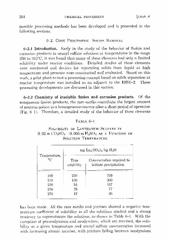
has been made. All the rare earths and yttrium showed a negative tem-perature coefficient of solubility in all the solutions studied and a strongtendency to supersaturate the solutions, as shown in Table 6-1 . With theexception of praseodymium and neodymium, which are reversed, the solu-bility at a given temperature and uranyl sulfate concentration increasedwith increasing atomic number, with yttrium falling between neodymium
TABLE 6- 1
SOLUBILITY OF LANTHANUM SULFATE IN
0 . 02 m U02SO4SOLUTION
0 . 005m H2SO4 AS ATEMPERATURE
FUNCTION OF
mg La2(S04)3/kg H2OTemperature,
°C Truesolubility
Concentrationinitiate precipitation
required to
190 250 760210 130 360230 54 167250 25 77270 12 36
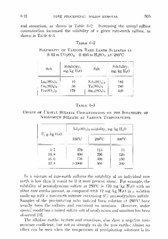
and samarium, as shown in Table 6-2 . Increasing the uranyl sulfateconcentration increased the solubility of a given rare-earth sulfate, asshown in Table G-3 .
In a mixture of rare-earth sulfates the solubility of an individual rareearth is less than it would be if it were present alone . For example, thesolubility of praseodymium sulfate at 280 °C is 170 mg/ kg H 2O with noother rare earths present, as compared with 12 mg, kg H 2O in a solutionmade up with a rare-earth mixture containing ( ; / praseodymium sulfate .Samples of the precipitating salts isolated from solution at 280 °C haveusually been the sulfates and contained no uranium . However, underspecial conditions a mixed sulfate salt of neodymium and uranium has beenobserved [3] .
The alkaline earths, barium and strontium, also show a negative tem-perature coefficient, but not so strongly as do the rare earths ; almost noeffect can be seen when the temperature of precipitating solutions is in-
TABLE 6-3
EFFECT OF URANYL SULFATE CONCENTRATION ON THE SOLUBILITY OFNEODYMIUM SULFATE AT VARIOUS TEMPERATURES
Nd2(S04)3 solubility, mg/kg H20U, g/kg H20
250 °C 280 °C 300°C
5 .7 270 115 7310 .8 400 200 12016 .6 770 300 18022 .4 > 1000 500 300
SOLUBILITY OF VARIOUS0 .02 m U 02S04
TABLE 6-2
RARE-EARTH SULFATES0 .005m H2SO4 AT 280 °C
IN
Salt mg/kgSolubility,
H20 Salt mg/kgSolubility,
H2O
La2(S04)3 10 Nd2(SO4 ) 3 110Ce2(S04)3 50 Y2(S04)3 240Pr 2(S0 4 ) 3 170 Sm2(S04)3 420

creased from 250 to 300 °C. At 295°C in 0.02 m U02S04-{1.005 m H2SO4solution, the solubility of barium sulfate is 7 mg/kg H2O and that ofstrontium sulfate is 21 mg/kg H20 . Both the alkaline and rare-earthsulfates show a strong tendency to precipitate on and adhere to steelsurfaces hotter than the precipitating solutions, and this property can beused to isolate these solids from liquids at high temperatures .
Other fission and corrosion product elements hydrolyze extensively at250 to 300°C and precipitate as oxides, leaving very low concentrationsin solution . Iron(III) at 285°C has a solubility of 0 .5 to 2 mg Fe/kg H 2Oand chromium(III), 2 to 5 mg/kg H20 . At 285°C less than 5 mg of zir-conium or niobium per kilogram of H 2O remains in solution .
For other elements of variable valence, such as technetium, the amountof the element in solution is determined by the stable valence state underreactor conditions . In general, the higher valence states better resist hy-drolysis and remain in solution . Thus at 275 °C in 0.02 m U02SO4 Te(VII)is reduced to Tc(IV) if hydrogen is present, and only 12 mg/kg H2O re-mains in solution . However, a slurry of Tc02 in the same solution but withoxygen present dissolves to give a solution at 275 °C with a technetiumconcentration of more than 9 g/kg H20. The same qualitative behavior isobserved with ruthenium . Selenium and tellurium in the hexapositive stateare much more soluble than when in the tetrapositive state [4] .
A few elements, e.g ., cesium, rubidium, nickel, and manganese, intro-duced into the fuel solution by fission or by corrosion of the system, arevery soluble under reactor conditions . Their removal and control are dis-cussed in Section 6-4 .
6-2.3 Experimental study of hydroclone performance . It is evidentfrom the preceding section that the amount of uranium withdrawn fromthe reactor diminishes if the collection, concentration, and isolation of theinsolubles can be effected at high temperature . One device capable ofcollecting and concentrating solids at high temperature is a solid-liquidcyclone separator called a "hydroclone," or "clone ." A diagram of a hydro-clone is shown in Fig . 6-4. In operation, a solids-bearing stream of liquidis injected tangentially into the wide portion of a conical vessel . Solidsconcentrate in a downward-moving layer of liquid and are discharged fromthe bottom of the clone into the underflow receiver . Partially clarifiedliquid leaves from the top of the clone through a vortex finder. Use of theunderflow receiver eliminates mechanical control of the discharge flowrate and, by proper choice of hydroclone dimensions, any desired ratio ofoverflow rate to underflow rate can be achieved . The driving force for thesystem is provided by a mechanical pump .
The factors influencing the design of an effective hydroclone for homo-geneous reactor processing use have been studied, and hydroclone designs
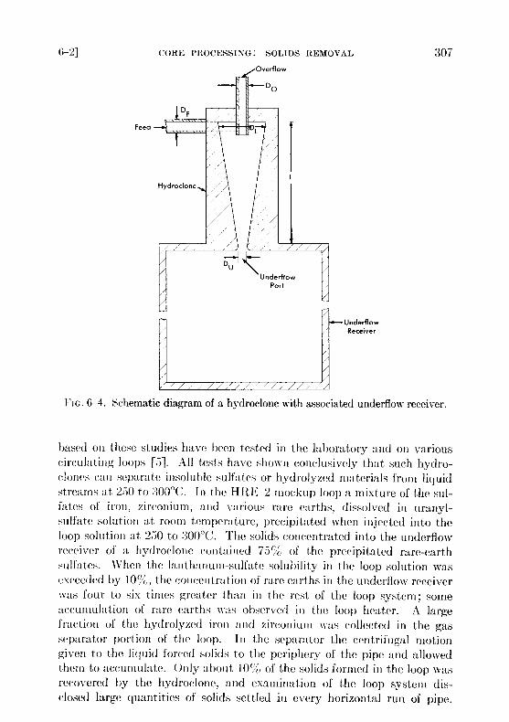
FIG. 6-4 . Schematic diagram of a hydroclone with associated underflow receiver .
based oil these studies have been tested in the laboratory and on variouscirculating loops [5] . All tests have shown conclusively that such hydro-clones can separate insoluble sulfates or hydrolyzed materials from liquidstreams at 250 to 300 °C. In the HRE-2 mockup loop a mixture of the sul-fates of iron, zirconium, and various rare earths, dissolved in uranyl-sulfate solution at room temperature, precipitated when injected into theloop solution at 250 to 300 °C. The solids concentrated into the underflowreceiver of a hydroclone contained 75% of the precipitated rare-earthsulfates . When the lanthanum-sulfate solubility in the loop solution wasexceeded by 10 U%, the concentration of rare earths in the underflow receiverwas four to six times greater than in the rest of the loop system ; someaccumulation of rare earths was observed in the loop heater . A largefraction of the hydrolyzed iron and zirconium was collected in the gasseparator portion of the loop . III the separator the centrifugal motiongiven to the liquid forced solids to the periphery of the pipe and allowedthem to accumulate . Only about 10`/, of the solids formed in the loop wasrecovered by the hydroclone, and examination of the loop system dis-closed large quantities of solids settled in every horizontal run of pipe .
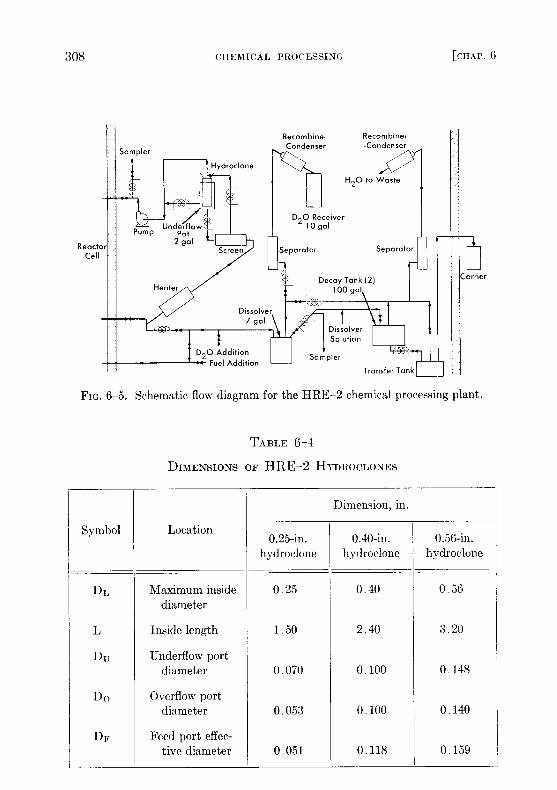
FIG . 6-5. Schematic flow diagram for the HRE-2 chemical processing plant .
TABLE 6-4
DIMENSIONS OF HRE-2 HYDROCLONES
Symbol Location
Dimension, in .
0 .25-in .hydroclone
0.40-in .hydroclone
0.56-in .hydroclone
DL Maximum insidediameter
0 .25 0 .40 0 .56
L
Du
Inside length
Underflow port
1 .50 2 .40 3 .20
Do
diameter
Overflow port
0 .070 0 .100 0 .148
DF
diameter
Feed port effec-
0 .053 0 .100 0 .140
tive diameter 0 .051 0 .118 0 .159
Samples taken from the loop after addition of preformed solids and withoutthe hydroclone operating showed an exponential decrease in solids concen-tration with a half-time of 2 .5 hr; with the hydroclone operating, the half-time was 1 .2 hr. In the HRE-2 chemical plant [5], operated with an aux-iliary loop to provide a slurry of preformed solids in uranyl sulfate solutionas a feed for the plant, the half-times for solids disappearance and removalwere 11 hr without the hydroclone and 1 .5 hr with it. The efficiency of thehydroclone for separating the particular solids used in these experimentsway about 10,' ;, . With gross amounts of solids in the system, concentrationfactors have been as large as 1700 .
Correlation of these data with anticipated reactor chemical plant oper-ating conditions indicates that the HRE-2 chemical plant will hold theamount of solids in the fuel solution to between 10 and 100 ppm. If neces-sary. performance can be improved by increasing the flow through thechemical plant and by eliminating, wherever possible, long runs of hori-zontal pipe with low liquid velocity and other stagnant areas which serveto accumulate solids .
6-2.4 HRE-2 chemical processing plant .* An experimental facility totest the solids-removal processing concept has been constructed in a celladjacent to the HRF-2 . A schematic flowsheet for this facility is shownin Fig. 6-5 .A 0.75-gpm bypass stream from the reactor fuel system at 280 °C and
1700 psi is circulated through the high-pressure system, consisting of aheater to make up heat losses, a screen to protect the hydroclone fromplugging, the hydroclone with underflow receiver, and a canned-rotorcirculating pump to make up pressure losses across the system . Thehydroclone is operated with an underflow receiver which is drained aftereach week of operation, at which time the processing plant is isolatedfrom the reactor system .
At the conclusion of each operating period 10 liters of the slurry in theunderflow pot is removed and sampled . The heavy water is evaporatedand recovered, and the solids are dissolved in sulfuric acid and sampledagain . The solution is then transferred under pressure to one of two 100-galdecay storage tanks . Following a three-month decay period, the solutionis transferred to a shielded carrier outside the cell and then to an existing>olvent extraction plant at Oak Ridge National Laboratory for uraniumdecontamination and recovery . The sulfuric acid solution step is incor-pono(d in the 1-111,1;-2 chemical plant to ensure obtaining a satisfactory-ample . This step would presumably not be necessary in a large-scaleplant .
*Contribution from 11' . D . Burch .
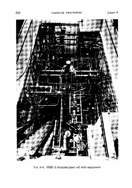
FIG. 6-6 . HRE-2 chemical plant cell with equipment .
All equipment is located in a 12- by 24- by 21-ft underground cell locatedadjacent to the reactor cell and separated from it by 4 ft of high-densityconcrete . Other construction features are similar to those of the reactorcell, with provisions for flooding the cell during maintenance periods inorder to use water as shielding. Figure 6-6, a photograph of the cell priorto installation of the roof plugs, shows the maze of piping necessitated bythe experimental nature of this plant .
Dimensions of the three sizes of hydroclones designed for testing in thisplant are shown in Table 6-4 . These three hydroclones, which have been
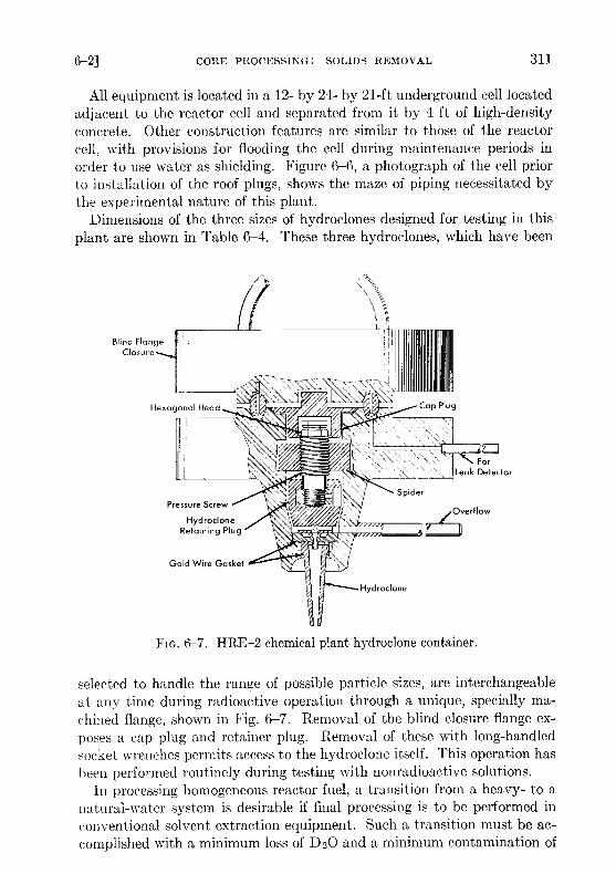
FIG. 6-7. HRE-2 chemical plant hydroclone container .
selected to handle the range of possible particle sizes, are interchangeableat any time during radioactive operation through a unique, specially ma-chined flange, shown in Fig. 6-7 . Removal of the blind closure flange ex-poses a cap plug and retainer plug . Removal of these with long-handledsocket wrenches permits access to the hydroclone itself . This operation hasbeen performed routinely during testing with nonradioactive solutions .
In processing homogeneous reactor fuel, a transition from a heavy- to anatural-water system is desirable if final processing is to be performed inconventional solvent extraction equipment . Such a transition must be ac-complished with a minimum loss of D20 and a minimum contamination of

the fuel solution by H 2O in recycled fuel . Initial tests of this step in thefuel processing cycle have been carried out [6]. In these experiments amixture of 57 D20, 957 H 2O was used to simulate reactor fuel liquid .The dissolver system was cycled three times between this liquid and or-dinary water, with samples being taken during each portion of each cycle .Isotopic analysis of these samples showed no dilution of the D20 in theenriched solution and no loss of D20 to the ordinary water system .
At expected corrosion rates, approximately 400 g of corrosion productswill be formed in the reactor system per week, and the underflow receiverwas therefore designed to handle this quantity of solids . The adequacy ofthe design was shown when more than three times this quantity of solidswas charged to the underflow receiver and drained in the normal way with-out difficulty .
Full-scale dissolution procedures have also been tested [6] . To minimizethe possibilities of contaminating the reactor fuel solution by foreign ions,a dissolution procedure was developed using only sulfuric acid . This con-sists of a 4-hr reflux with 10 .8 M H2S04 in a tantalum-lined dissolver fol-lowed by a 4-hr reflux with 4 AI H2SO4, and repeated as required untildissolution is complete . Decay storage tanks and other equipment requiredto handle the boiling 4 M H2S04 are fabricated of Carpenter-20 stainlesssteel. Tests have repeatedly demonstrated more than 99 .57 dissolutionof simulated corrosion and fission products in two such cycles .The HRE-2 hydroclone system has been operated as an integral part
of the reactor system for approximately 600 hr and for an additional1200 hr with a temporary pump loop during initial solids-removal tests .During this operating period, in which simulated nonradioactive fuelsolutions were used, the performance of the plant was satisfactory in allrespects .
6-3. Fission PRODUCT GAS DISPOSAL*
6-3.1 Introduction . To prevent the pollution of the atmosphere byradioactive krypton and xenon isotopes released from the fuel solution, asystem of containment must be provided until radioactive decay has re-duced their activity level . This is accomplished by a method based on theprocess of physical adsorption on solid adsorber materials . If the adsorbersystem is adequately designed, the issuing gas stream will be composed oflong-lived Krs 5, oxygen, inert krypton isotopes, inert xenon isotopes, andinsignificant amounts of other radioactive krypton and xenon isotopes . Incase the activity of the KrS 5 is too high for dilution with air and dischargeto the atmosphere, the mixture may be stored after removal of the oxygen
*Contribution from W . E. Browning .
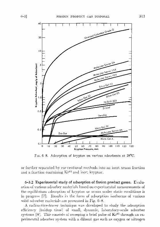
Fic .6-8. Adsorption of krypton on various adsorbents at 28 °C .
or further separated by conventional methods into an inert xenon fractionand a fraction containing Kr8 ' and inert krypton .
6-3 .2 Experimental study of adsorption of fission product gases . Evalu-ation of various adsorber materials based on experimental measurements ofthe equilibrium adsorption of krypton or xenon under static conditions isin progress [7] . Results in the form of adsorption isotherms of varioussolid adsorber materials are presented in Fig . 6-8 .
A radioactive-tracer technique was developed to study the adsorptionefficiency (holdup time) of small, dynamic, laboratory-scale adsorbersystems [8] . This consists of sweeping a brief pulse of Kr 83 through an ex-perimental adsorber system with a diluent gas such as oxygen or nitrogen
and monitoring the effluent gases for Kr85 beta activity. The activity inthe gas stream versus time after injection of the pulse of Kr 85 is recorded .A plot of the data gives an experimental elution curve, such as shown inFig. 6-9, from which various properties of an adsorber material and ad-sorber system may be evaluated .Among the factors which influence the adsorption of fission product
gases from a dynamic system are (1) adsorptive capacity of adsorber ma-terial, (2) temperature of adsorber material, (3) volume flow rate of gasstream, (4) adsorbed moisture content of adsorber material, (5) composi-tion and moisture content of gas stream, (6) geometry of adsorber system,and (7) particle size of adsorber material . The average time required forthe fission product gas to pass through an adsorber system, tmax, is influ-enced by the first five of the above factors . The shape 'of the experimentalelution curve is affected by the last two .
The temperature of the adsorber material is of prime importance . Thelower the temperature the greater will be the adsorption of the fission gases,and therefore longer holdup times per unit mass of adsorber material willresult. The dependence of adsorptive capacity, k, on temperature as de-termined by holdup tests with some solid adsorber materials is shown inTable 6-5 .
TABLE 6-5
ADSORPTIVE CAPACITY OF VARIOUS MATERIALS AS A FUNCTION
OF TEMPERATURE
Gas Diluent Adsorbercc gas/g
273°K
adsorbent*
323°K 373°K
Xe
Kr
Kr
Kr
Kr
02
He
02 or N2
02
02
Charcoal
Charcoal
Charcoal,
Linde MolecularSieve 5A
Linde MolecularSieve lox
4 .7 X 103
1 .8 X 102
68
23
11
4 .0 X 10 2
34
24
9
5 .7
80 .0
9 .6
11 .0
4 .5
3 .5
*Gas volume measured at temperatures indicated .
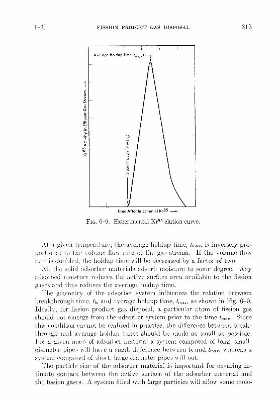
FIG. 6-9 . Experimental Kr85 elution curve .
At a given temperature, the average holdup time, tmax, is inversely pro-portional to the volume flow rate of the gas stream . If the volume flowrate is doubled, the holdup time will be decreased by a factor of two .
All the solid adsorher materials adsorb moisture to some degree . Anyadsorbed moisture reduces the active surface area available to the fissiongases and thus reduces the average holdup time .
The geometry of the adsorber system influences the relation betweenbreakthrough time, tb, and average holdup time, t max , as shown in Fig . 6-9 .Ideally, for fission product gas disposal, a particular atom of fission gasshould not emerge from the adsorber system prior to the time t,,, ax . Sincethis condition cannot be realized in practice, the difference between break-through and average holdup times should be made as small as possible .For a given mass of adsorber material a system composed of long, small-diameter pipes will have a small difference between tb and t,nax, whereas asystem composed of short, large-diameter pipes will not .
The particle size of the adsorber material is important for ensuring in-timate contact between the active surface of the adsorber material andthe fission gases . A system filled with large particles will allow some mole-
cules of fission gases to penetrate deeper into the system before contact ismade with an active surface, while the pressure drop across a long trapfilled with small particles may be excessive . Material between 8 and 14mesh in size is satisfactory from both viewpoints .
6-3 .3 Design of a fission product gas adsorber system . The design ofan adsorber system will be determined partly by the final disposition ofthe effluent gas mixture . If ultimate disposal is to be to the atmosphere,the adsorber system should be designed to discharge only Kr 8' plus inertkrypton and xenon isotopes. If the effluent gases are to be contained andstored, the adsorber system may be designed to allow discharge of otherradioactive krypton and xenon isotopes . In the following discussion it isassumed that final disposal of the effluent gas mixture will be to the at-mosphere. The following simple relation has been developed which is use-ful in finding the mass of adsorber material in such an adsorber system :
M = tmax,
where A1= mass of adsorber material (grams), F = gas volume flow ratethrough adsorber system (cc/min), k = adsorptive capacity under dy-namic conditions (cc/g), and tmax = average holdup time (min) .
The operating characteristics of the reactor will dictate the compositionand volume flow rate of the gas stream ; tmn x will be determined by the al-lowable concentration of radioactivity in the effluent gas ; k values forkrypton and xenon must be determined experimentally under conditionssimulating these in the full-scale adsorber system . It should be noted(Fig. 6-9) that a portion of the fission gas will emerge from the adsorbersystem at a time th prior to the average holdup time, tmax . The designshould ensure that radioactive gas emerging at time to has decayed suffi-ciently that only insignificant amounts of activity other than KrS 5 will bedischarged from the bed .
The adsorber system should be operated at the lowest convenienttemperature because of the dependence of adsorptive capacity on tempera-ture. Beta decay of the fission product gases while passing through theadsorber system will increase the temperature of the adsorber materialand reduce the adsorptive capacity . Temperature control is especiallycritical if the adsorber system uses a combustible adsorber material, suchas activated charcoal, with oxygen as the diluent or sweep gas .
6-3.4 HRE-2 fission product gas adsorber system . The HRE-2 uses afission product gas adsorber system containing Columbia G activatedcharcoal. Oxygen, contaminated with the fission product gases, is removed
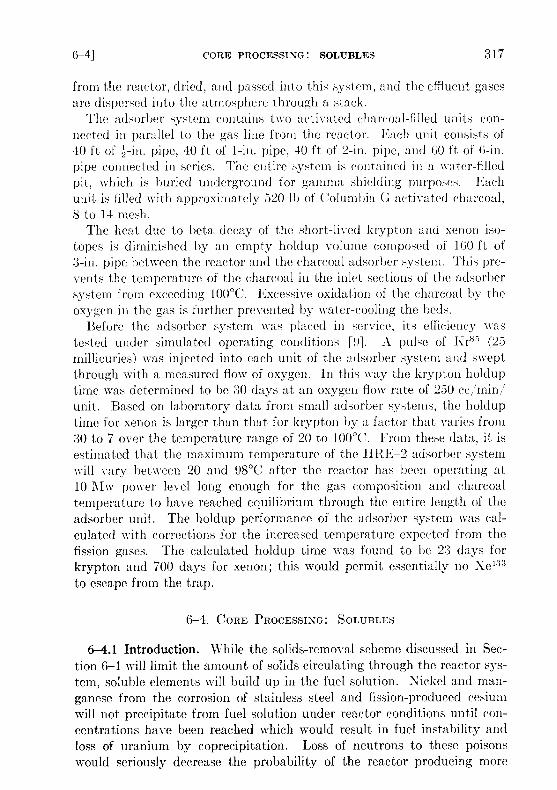
from the reactor, dried, and passed into this system, and the effluent gasesare dispersed into the atmosphere through a stack .
The adsorber system contains two activated charcoal-filled units con-nected iii parallel to the gas line from the reactor . Each unit consists of40 ft of z-in . pipe, 40 ft of 1-in . pipe, 40 ft of 2-in . pipe, and 60 ft of 6-in .pipe connected in series . The entire system is contained in a water-filledpit, which is buried underground for gamma shielding purposes . Eachunit is filled with approximately 520 11) of Columbia G activated charcoal,8 to 14 mesh .
The heat due to beta decay of the short-lived krypton and xenon iso-topes is diminished by an empty holdup volume composed of 160 ft of3-in . pipe between the reactor and the charcoal adsorber system . This pre-vents the temperature of the charcoal in the inlet sections of the adsorbersystem from exceeding 100°C . Excessive oxidation of the charcoal by theoxygen in the gas is further prevented by water-cooling the beds .
Before the adsorber system was placed in service, its efficiency wastested under simulated operating conditions [9] . A pulse of Krss (23millicuries) was injected into each unit of the adsorber system and sweptthrough with a measured flow of oxygen . In this way the krypton holduptime was determined to be 30 days at an oxygen flow rate of 230 cc/min/unit. Based on laboratory data from small adsorber systems, the holduptime for xenon is larger than that for krypton by a factor that varies from30 to 7 over the temperature range of 20 to 100 °C. From these data, it isestimated that the maximum temperature of the HRE-2 adsorber systemwill vary between 20 and 98°C after the reactor has been operating at10 Alw power level long enough for the gas composition and charcoaltemperature to have reached equilibrium through the entire length of theadsorber unit. The holdup performance of the adsorber system was cal-culated with corrections for the increased temperature expected from thefission gases . The calculated holdup time was found to be 23 days forkrypton and 700 days for xenon ; this would permit essentially no Xe 133to escape from the trap .
6-4. CORE PROCESSING : SOLUBLES
6-4.1 Introduction . While the solids-removal scheme discussed in Sec-tion 6-1 will limit the amount of solids circulating through the reactor sys-tem, soluble elements will build up in the fuel solution . Nickel and man-ganese from the corrosion of stainless steel and fission-produced cesiumwill not precipitate from fuel solution under reactor conditions until con-centrations have been reached which would result in fuel instability andloss of uranium by coprecipitation . Loss of neutrons to these poisonswould seriously decrease the probability of the reactor producing more
fuel than it consumes. Therefore, a volume of fuel solution sufficient toprocess the core solution of the reactor at a desired rate for removal ofsoluble materials is discharged along with the insoluble materials concen-trated into the hydroclone underflow pot. This rate of removal of solublematerials depends on the nature of other chemical processing being doneand on the extenWof corrosion . For example, operation of an iodine re-moval plant (Section 6-5) reduces the buildup of cesium in the fuel to aninsignificant value by removing cesium precursors .
6-4.2 Solvent extraction . Processing of the core solution of a homo-geneous reactor by solvent extraction is the only method presently avail-able which has been thoroughly proved in practice . However, the amountof uranium to be processed daily is so small that operation of a solvent ex-traction plant just for core solution processing would be unduly expensive .Therefore, the core solution would normally be combined with blanket ma-terial from a thermal breeder reactor and be processed through a Thorexplant, but with a plutonium-producing reactor separate processing of coreand blanket materials will be needed . These process schemes are discussedin detail in Sections 6-6 and 6-7 .
The uranium product from either process would certainly be satisfactoryfor return to the reactor . Since solid fuel element refabrication is not aproblem with homogeneous reactors, decontamination factors of 10 to 100from various nuclides are adequate and some simplification of presentsolvent extraction schemes may be possible .
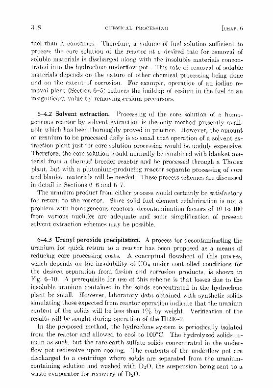
6-4.3 Uranyl peroxide precipitation . A process for decontaminating theuranium for quick return to a reactor has been proposed as a means ofreducing core processing costs . A conceptual flowsheet of this process,which depends on the insolubility of U04 under controlled conditions forthe desired separation from fission and corrosion products, is shown inFig. 6-10. A prerequisite for use of this scheme is that losses due to theinsoluble uranium contained in the solids concentrated in the hydrocloneplant be small . However, laboratory data obtained with synthetic solidssimulating those expected from reactor operation indicate that the uraniumcontent of the solids will be less than 1°%o by weight . Verification of theresults will be sought during operation of the HRE-2 .
In the proposed method, the hydroclone system is periodically isolatedfrom the reactor and allowed to cool to 100 °C. The hydrolyzed solids re-main as such, but the rare-earth sulfate solids concentrated in the under-flow pot redissolve upon cooling . The contents of the underflow pot aredischarged to a centrifuge where solids are separated from the uranium-containing solution and washed with D20, the suspension being sent to awaste evaporator for recovery of D20 .
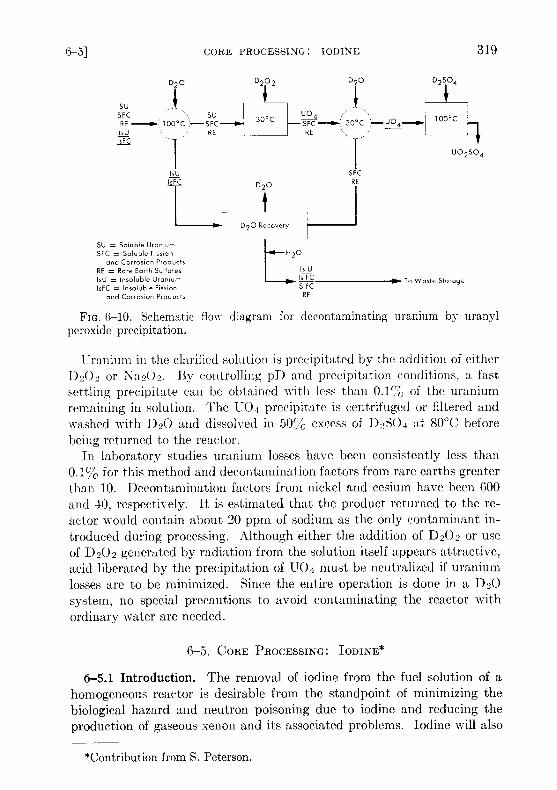
FIG. 6-10 . Schematic flow diagram for decontaminating uranium by uranylperoxide precipitation .
Uranium in the clarified solution is precipitated by the addition of eitherD202 or \a202. By controlling pD and precipitation conditions, a fastsettling precipitate can be obtained with less than 0 .1 1/'c of the uraniumremaining in solution . The U04 precipitate is centrifuged or filtered andwashed with D20 and dissolved in 50% excess of D 2S0 4 at 80 °C beforebeing returned to the reactor .
In laboratory studies uranium losses have been consistently less than0.1% for this method and decontamination factors from rare earths greaterthan 10. Decontamination factors from nickel and cesium have been 600and 40, respectively. It is estimated that the product returned to the re-actor would contain about 20 ppm of sodium as the only contaminant in-troduced during processing . Although either the addition of D202 or useof D202 generated by radiation from the solution itself appears attractive,acid liberated by the precipitation of U04 must be neutralized if uraniumlosses are to be minimized . Since the entire operation is done in a D20system, no special precautions to avoid contaminating the reactor withordinary water are needed .
6-5 . CORE PROCESSING : IODINE*
6-5.1 Introduction . The removal of iodine from the fuel solution of ahomogeneous reactor is desirable from the standpoint of minimizing thebiological hazard and neutron poisoning due to iodine and reducing theproduction of gaseous xenon and its associated problems . Iodine will also
*Contribution from S . Peterson .
poison platinum catalysts [10] used for radiolytic gas recombination inthe reactor low-pressure system and may catalyze the corrosion of metalsby the fuel solution . For this reason a considerable effort has been carriedout at OIINI, and by Vitro [11] to investigate the behavior of iodine insolution and to develop methods for its removal . In this regard, the iodineisotopes of primary interest are 8-day 131 and 6 .7-hr 1 13 `'
6-5.2 The chemistry of iodine in aqueous solutions . Iodine in aqueoussolution at 25 °C can exist in several oxidation states . The stable speciesare iodide ion, I - ; elemental iodine, 12 ; iodate, 10,;- ; and periodate, 104or H510(j. The last of these exists only under very strongly oxidizing con-ditions, and is immediately reduced under the conditions expected for ahomogeneous reactor fuel . Iodide ion can be formed from reduction ofother states by metals, such as stainless steel, but in the presence of theoxygen necessary in a reactor system it is readily converted to elementaliodine ; this conversion is especially rapid above 200 °C . Thus the onlystates of concern in reactor fuel solutions are elemental iodine and iodate .Under the conditions found in a high-pressure fuel system the iodine islargely, if not all, in the elemental form .
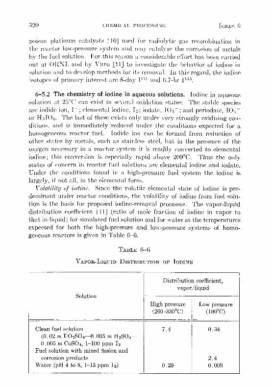
Volatility of iodine . Since the volatile elemental state of iodine is pre-dominant under reactor conditions, the volatility of iodine from fuel solu-tion is the basis for proposed iodine-removal processes . The vapor-liquiddistribution coefficient [11] (ratio of mole fraction of iodine in vapor tothat in liquid) for simulated fuel solution and for water at the temperaturesexpected for both the high-pressure and low-pressure systems of homo-geneous reactors is given in Table 6-6 .
TABLE 6-6
VAPOR-LIQUID DISTRIBUTION OF IODINE
Distribution coefficient,vapor/liquid
SolutionHigh pressure Low pressure(260-330°C) (100°C)
Clean fuel solution 7 .4 0.34(0 .02 m U02SO4-0 .005 m H2SO4-0 .005 M CuSO4, 1-100 ppm 12
Fuel solution with mixed fission andcorrosion products 2.4
Water (pH 4 to 8, 1-13 ppm 1 2 ) 0 .29 0.009
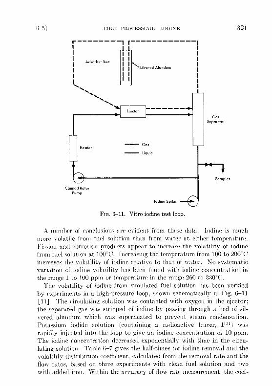
FIG. 6-11 . Vitro iodine test loop .
A number of conclusions are evident from these data . Iodine is muchmore volatile from fuel solution than from water at either temperature .Fission and corrosion products appear to increase the volatility of iodinefrom fuel solution at 100 °C. Increasing the temperature from 100 to 200 °Cincreases the volatility of iodine relative to that of water. No systematicvariation of iodine volatility has been found with iodine concentration inthe range 1 to 100 ppm or temperature in the range 260 to 330 °C .
The volatility of iodine from simulated fuel solution has been verifiedby experiments in a high-pressure loop, shown schematically in Fig . 6-11[I]]. The circulating solution was contacted with oxygen in the ejector ;the separated gas was stripped of iodine by passing through a bed of sil-vered alundum which was superheated to prevent steam condensation .Potassium iodide solution (containing a radioactive tracer, 1 131 ) wasrapidly injected into the loop to give an iodine concentration of 10 ppm .The iodine concentration decreased exponentially with time in the circu-lating solution. Table 6-7 gives the half-times for iodine removal and thevolatility distribution coefficient, calculated from the removal rate and theflow rates, based on three experiments with clean fuel solution and twowith added iron . Within the accuracy of flow rate measurement, the coef-
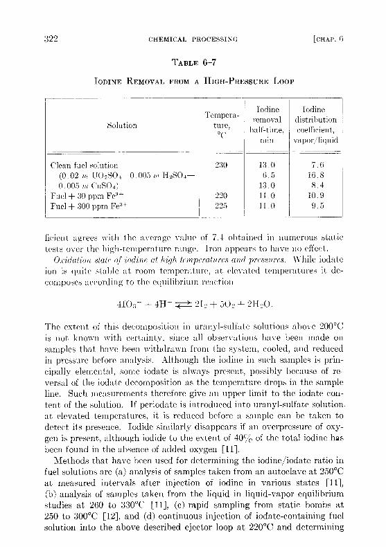
ficient agrees with the average value of 7 .4 obtained in numerous static
tests over the high-temperature range . Iron appears to have no effect .Oxidation state of iodine at high temperatures and pressures . While iodate
ion is quite stable at room temperature, at elevated temperatures it de-composes according to the equilibrium reaction
4103 --}- 411 + { 212+502+21120 .
The extent of this decomposition in uranyl-sulfate solutions above 200 °C
is not known with certainty, since all observations have been made onsamples that have been withdrawn from the system, cooled, and reducedin pressure before analysis . Although the iodine in such samples is prin-cipally elemental, some iodate is always present, possibly because of re-versal of the iodate decomposition as the temperature drops in the sample
line. Such measurements therefore give an upper limit to the iodate con-
tent of the solution. If periodate is introduced into uranyl-sulfate solution-at elevated temperatures, it is reduced before a sample can be taken to
detect its presence . Iodide similarly disappears if an overpressure of oxy-
gen is present, although iodide to the extent of 401-/, of the total iodine hasbeen found in the absence of added oxygen [11] .
Methods that have been used for determining the iodine/iodate ratio infuel solutions are (a) analysis of samples taken from an autoclave at 250 °Cat measured intervals after injection of iodine in various states [11],
(b) analysis of samples taken from the liquid in liquid-vapor equilibriumstudies at 260 to 330°C [11], (c) rapid sampling from static bombs at
250 to 300°C [12], and (d) continuous injection of iodate-containing fuelsolution into the above described ejector loop at 220 °C and determining
TABLE 6-7
IODINE REMOVAL FROM A HIGH-PRESSURE Loop
SolutionTempera-
turn,°C
Iodineremovalhalf-tune,
min vapor/
Iodinedistributioncoefficient,
liquid
Clean fuel solution 230 13 .0 7 .6(0 .02 1n U02S0 .1-0 .005 in H2SO4- 6 .5 16 .80 .005 M CUSO4) 13 .0 8 .4
Fuel + 30 ppm Fee+ 220 11 .0 10 .9Fuel + 300 ppm Fe -3+ 225 11 .0 9 .5
oxidation states in samples withdrawn [11] . The iodine/iodate ratio inthese samples has varied from slightly over 1 to about 70, with no apparentrelation to variations in temperature, oxygen pressure, and total iodineconcentration .
The strongest indication of iodate instability was in the loop experi-ments, which gave the highest observed iodine/iodate ratio, even thoughiodine was continuously introduced into the flowing stream as iodateand removed by oxygen scrubbing as elemental iodine . The low iodatecontent of the samples from these experiments corresponded to a first-order iodate decomposition rate constant of 6 .2 min' . Iodate con-tents averaging about 10% of the total iodine have been observed in0.04 m U02S04-0.005 m CuSO4-H2SO4 solution, rapidly sampled froma static bomb through an ice-cooled titanium sample line . The observediodate content was unrelated to whether the free sulfuric acid concentra-tion was 0.02 or 0 .03 m, whether the temperature was 250 or 300 °C, andwhether or not the solution was exposed to cobalt gamma radiation at anintensity of 1 .7 watts/kg .
Oxidation state of iodine at low temperatures . At 100°C the iodate de-composition and iodine oxidation are too slow for equilibrium to be es-tablished in reasonable periods of time . Thus both states can persist undersimilar conditions . In stainless-steel equipment both states are reduced toiodide, which is oxidized to iodine if oxygen or iodate is present [12] .
In a radiation field the iodide is oxidized, iodine is oxidized if sufficientoxygen is present, and iodate is reduced [13] . At the start of irradiation,iodate is reduced, but in the presence of sufficient oxygen, iodine is laterreoxidized to iodate, probably by radiation-produced hydrogen peroxidewhich accumulates in the solution . Finally, a steady state is reached with aproportion of iodate to total iodine which is independent of total iodine con-centration from 10-6 to 10 m and temperatures from 100 to 110 °C, butstrongly dependent on uranium and acid concentrations and on the hydro-gen/oxygen ratio in the gas phase . When the temperature is increased to120°C there is a marked decrease in iodate stability under all conditions ofgas and solution composition. Experimental data on the effects of radiationintensity, temperature, and gas composition for the irradiation of a typicalfuel solution containing 0 .04 m U 02SO4-0.01 m H2SO4-0.005 M CuSO4are given in Ref . 13. The steady-state iodate percentages are also given inthis reference .
6-5 .3 Removal of iodine from aqueous homogeneous reactors . It isclear that under the operating conditions of a power reactor, iodine in thethe fuel solution is mainly in the volatile elemental state . It can thereforebe removed by sweeping it from the solution into a gas phase, stripping
it from the gas stream by trapping it in a solid absorber or by contacting thegas with a liquid .
Numerous experiments have shown that silver supported on alundum isa very effective reagent for removing iodine from gas or vapor systems,although its efficiency is considerably reduced at temperatures below150°C . Silver-plated Yorkmesh packing is very effective for removingiodine from vapor streams in the range 100 to 120°C. In one in-pile ex-periment [14] 90% of the fission-product iodine was concentrated in asilvered-alundum pellet suspended in the vapor above a uranyl-sulfatesolution . This method of using a solid iodine absorber, however, wouldpresent difficult engineering problems, since xenon resulting from iodinedecay would be expected to leave the absorber and return to the core unlessthe absorbers were isolated after short periods of use and remotely replaced .
Iodine removal by gas stripping requires a continuous fuel letdown . Incase this is not desirable, the vapor can be stripped of iodine in the high-pressure system by contacting with a small volume of liquid which is sub-sequently discharged . Liquids considered include water and aqueoussolutions of alkali, sodium sulfite, or silver sulfate [1.1] . Although the so-lutions are much more effective iodine strippers than pure water, their userequires elaborate provision for preventing entrainment in the gas and sub-sequent contamination of the fuel solution . Thus most of the effort indesign of iodine-removal systems is based on stripping by pure heavywater .
One possible iodine-removal scheme uses 0 2 or 02 + D2 stripping [15] .The iodine is scrubbed from the fuel solution by the gas in one contactorand then stripped from the gas by heavy water in a second contactor . Thiswater would then be let down to low pressure and stored for decay or proc-essed to remove iodine .
In most homogeneous reactors some of the fuel solution is evaporatedto provide condensate for purge of the circulating pump and pressurizer .Since iodine is stripped from the fuel by this evaporation this operation canbe used for iodine removal . This method, which is illustrated in Fig . 6-12,has been proposed for the HRE-3 [16] . Here a stream of the fuel solutionis scrubbed with oxygen in the pressurizer. The steam is condensed and theoxygen recycled . The condensate is distilled to concentrate the iodine intosuch a small volume that its letdown does not complicate reactor operation .Iodine removal in the HRE-2 . Iodine adsorption on the platinized alu-
mina recombination catalyst, such as that used in the HRE-2, poisons thecatalyst severely [10] . Although the catalyst can be restored by operationat 650°C, this would not be feasible in HRE-2 operation . A method forremoving iodine from the gas stream by contact with alundum or York-mesh coated with silver was developed in the HRT mockup . Iodine wasintroduced into the system and vapor from the letdown stream and dump
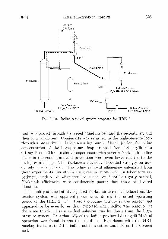
FIG. 6-12 . Iodine removal system proposed for HRE-3 .
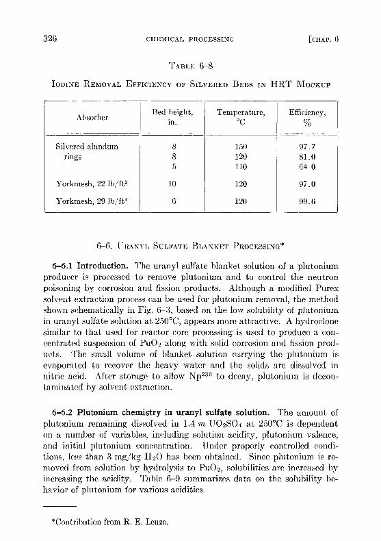
tank was passed through a silvered alundum bed and the recombiner, andthen to a condenser . Condensate was returned to the high-pressure loopthrough a pressurizer and the circulating pump . After injection, the iodineconcentration of the high-pressure loop dropped from 1.8 mg/liter to0.1 mg ,'liter in 2 hr . In similar experiments with silvered Yorkmesh, iodinelevels in the condensate and pressurizer were even lower relative to thehigh-pressure loop . The Yorkmesh efficiency depended strongly on howdensely it was packed . The iodine removal efficiencies calculated fromthese experiments and others are given in Table 6-8 . In laboratory ex-periments with a 1-in .-diameter bed which could not be tightly packed,Yorkmesh efficiencies were consistently poorer than those of silveredalundum .
The ability of a bed of silver-plated Yorkmesh to remove iodine from thereactor system was apparently confirmed during the initial operatingperiod of the HRE-2 [17] . Here the iodine activity in the reactor fuelappeared to be even lower than expected when iodine was removed atthe same fractional rate as fuel solution was let down from the high-pressure system . Less than 3% of the iodine produced during 40 Mwh ofoperation was found in the fuel solution . Experience with the HRTmockup indicates that the iodine not in solution was held on the silveredbed .
6-6 . URANYL SULFATE BLANKET PROCESSING*
6-6.1 Introduction. The uranyl sulfate blanket solution of a plutoniumproducer is processed to remove plutonium and to control the neutronpoisoning by corrosion and fission products. Although a modified Purexsolvent extraction process can be used for plutonium removal, the methodshown schematically in Fig. 6-3, based on the low solubility of plutoniumin uranyl sulfate solution at 250 °C, appears more attractive. A hydroclonesimilar to that used for reactor core processing is used to produce a con-centrated suspension of Pu02 along with solid corrosion and fission prod-ucts . The small volume of blanket solution carrying the plutonium isevaporated to recover the heavy water and the solids are dissolved innitric acid. After storage to allow Np 23s to decay, plutonium is decon-taminated by solvent extraction .
6-6.2 Plutonium chemistry in uranyl sulfate solution . The amount ofplutonium remaining dissolved in 1 .4 m U02S04 at 250 °C is dependenton a number of variables, including solution acidity, plutonium valence,and initial plutonium concentration . Under properly controlled condi-tions, less than 3 mg/kg H2O has been obtained . Since plutonium is re-moved from solution by hydrolysis to Pu02, solubilities are increased byincreasing the acidity . Table 6-9 summarizes data on the solubility be-havior of plutonium for various acidities.
*Contribution from R . E. Leuze .
TABLE 6-8
IODINE REMOVAL EFFICIENCY OF SILVERED BEDS IN HRT MOCKUP
AbsorberBed height,
in.Temperature,
CEfficiency,
%
Silvered alundum 8 150 97 .7rings 8 120 81 .0
5 110 64 .0
Yorkmesh, 22 lb/ft 3 10 120 97 .0
Yorkmesh, 29 lb/ft 3 6 120 99 .6

Plutonium behavior is difficult to predict because of its complex valencepattern . In the absence of irradiation, plutonium dissolved in 1 .4 m U02SO4under a stoichiometric mixture of hydrogen and oxygen at 250 °C exists inthe tetrapositive state . However, when dissolved chromium is present orwhen an overpressure of pure oxygen is used, part of the plutonium is oxi-dized to the hexapositive state. Experiments indicate that in the presenceof Co60 gamma irradiation [18], reducing conditions prevail even under anoxygen pressure and plutonium is held in the tetrapositive state . Thevalence behavior discussed here is somewhat in question, since actualvalence measurements were made at room temperature immediately aftercooling from 250°C. It is known that tetrapositive plutonium will dispro-portionate upon heating [19] . The disproportionation in a sulfate systemis depressed by the sulfate complex formation with tetrapositive plu-tonium . These results indicate that plutonium in a reactor will be pre-dominantly in the tetrapositive state .
When the plutonium concentration exceeds the solubility limit, plu-tonium will hydrolyze to form small particles of Pu02 about 0 .5 micronin diameter and in pyrex, quartz, or gold equipment forms a loose preci-pitate with negligible amounts adsorbed on the walls . However, if thesesolutions are contained in type-347 stainless steel, titanium, or Zircaloy,a large fraction of the Pu02 adsorbs on and becomes incorporated withinthe oxide corrosion film . Attempts to saturate these metal surfaces withplutonium in small-scale laboratory experiments were unsuccessful eventhough plutonium adsorption was as much as 1 mg/cm 2 .
6-6.3 Neptunium chemistry in uranyl sulfate solution . Neptunium dis-solved in 1.4 m U02SO4 at 250 °C under air, stoichiometric mixture hy-drogen and oxygen, or oxygen is stable in an oxidized valence state, prob-
TABLE 6-9
SOLUBILITY OF TETRAVALENT PLUTONIUMIN 1.4 m U02SO4 AT 250°C
Excess sulfuric acid,m
Pu(IV) solubility,mg/kg H20
0 3 .70 .1 170 .2 390 .3 680 .4 105
ably Np(V). The solubility is not known, but it is greater than 200 mg/kgH20. Since the equilibrium concentration is only about 50 mg/kg H 20,for a 1 .4 m U02SO4 blanket with an average flux of 1 .8 X 10 14 neu-trons/(cm 2)(sec), all the neptunium should remain in solution in mostreactor designs .
6-6.4 Plutonium behavior under simulated reactor conditions. Pluto-nium behavior in actual uranyl sulfate blanket systems has not beenstudied ; however, small-scale static experiments with 100 ml of solutionand circulating loop experiments with 12 liters of solution have been car-ried out in the absence of irradiation under conditions similar to those ex-pected in an actual reactor .
In the static experiments, plutonium was added batchwise to 1 .4 mU02SO4 at a rate of about 6 mg/kg H20/day . The solution was heatedovernight in a pyrex-lined autoclave at 250°C under 200 psi hydrogen and100 psi oxygen. The solution was cooled to room temperature for analysisand for adding more plutonium . This was repeated until a total of 140 mgof plutonium per kilogram of water was added . Small disks of type-347stainless steel were suspended in the solution throughout the experiment todetermine the amount of plutonium adsorption . The behavior of plu-tonium for a stainless-steel surface area/solution volume ratio of 0 .6 cm 2/mlis shown in Fig . 6-13. As the plutonium concentration was gradually in-creased to 45 mg/kg H2O, essentially all the plutonium remained in solu-tion as Pu(VI) . There was a small amount of adsorption, but no precipita-tion. During the next few additions the amount of plutonium in solutiondecreased rapidly to about 5 mg/kg H2O. At the same time there was arapid increase in plutonium adsorption and in the formation of a loosePu02 precipitate . All plutonium added after this was either adsorbed orprecipitated .
Other experiments were made with surface/volume ratios of 0.2 and0.4 cm 2/ml. In all cases, the plutonium remaining in solution and the plu-tonium adsorption per square centimeter were essentially the same asthat shown in Fig. 6-13. Thus, by decreasing the surface/volume ratio,it is possible to increase the amount of plutonium in the loose precipitate .For example, when the total plutonium addition was 130 mg/kg H2O, 40%of the plutonium was as a loose precipitate for a surface/volume ratio of0.6 cm 2/ml, 60% for a ratio of 0.4 cm 2/ml, and 68% for a ratio of0.2 cm 2/ml .
Plutonium behavior under dynamic conditions was studied by injectingdissolved plutonium sulfate and preformed PuO2 into a circulating streamof 12 liters of 1 .4 m U02SO4 at 250°C under 350 psi oxygen. This solutionwas contained in a type-347 stainless steel loop equipped with a cannedrotor pump, a hydroclone, metal adsorption coupon holders, and a small
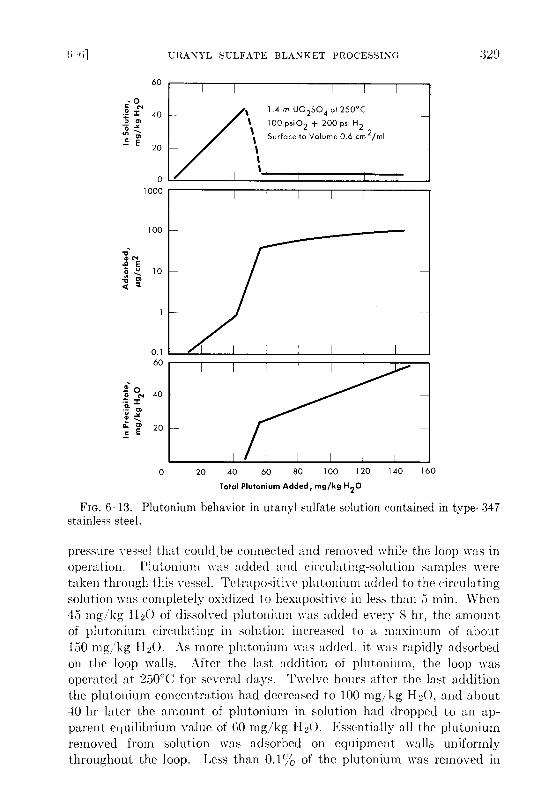
FIG. 6-13 . Plutonium behavior in uranyl sulfate solution contained in type-347stainless steel .
pressure vessel that could ,be connected and removed while the loop was inoperation. Plutonium was added and circulating-solution samples weretaken through this vessel . Tetrapositive plutonium added to the circulatingsolution was completely oxidized to hexapositive in less than 5 min . When45 mg/kg H2O of dissolved plutonium was added every 8 hr, the amountof plutonium circulating in solution increased to a maximum of about150 mg/kg 1120 . As more plutonium was added, it was rapidly adsorbedon the loop walls . After the last addition of plutonium, the loop wasoperated at 250°C for several days. Twelve hours after the last additionthe plutonium concentration had decreased to 100 mg/kg H2O, and about40 hr later the amount of plutonium in solution had dropped to an ap-parent equilibrium value of 60 mg/kg 1120 . Essentially all the plutoniumremoved from solution was adsorbed on equipment walls uniformlythroughout the loop. Less than 0 .1% of the plutonium was removed in
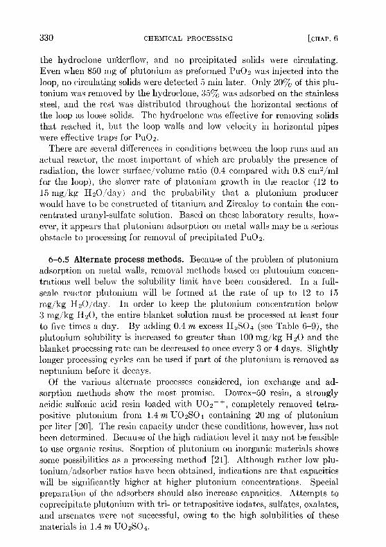
the hydroclone underflow, and no precipitated solids were circulating .Even when 850 mg of plutonium as preformed Pu02 was injected into theloop, no circulating solids were detected 5 min later . Only 20% of this plu-tonium was removed by the hydroclone, 35% was adsorbed on the stainlesssteel, and the rest was distributed throughout the horizontal sections ofthe loop as loose solids . The hydroclone was effective for removing solidsthat reached it, but the loop walls and low velocity in horizontal pipeswere effective traps for Pu02 .
There are several differences in conditions between the loop runs and anactual reactor, the most important of which are probably the presence ofradiation, the lower surface/volume ratio (0 .4 compared with 0 .8 cm2/mlfor the loop), the slower rate of plutonium growth in the reactor (12 to15 mg/kg H2O/day) and the probability that a plutonium producerwould have to be constructed of titanium and Zircaloy to contain the con-centrated uranyl-sulfate solution . Based on these laboratory results, how-ever, it appears that plutonium adsorption on metal walls may be a seriousobstacle to processing for removal of precipitated Pu02 .
6-6.5 Alternate process methods . Because of the problem of plutoniumadsorption on metal walls, removal methods based on plutonium concen-trations well below the solubility limit have been considered . In a full-scale reactor plutonium will be formed at the rate of up to 12 to 15mg/kg H2O/day . In order to keep the plutonium concentration below3 mg/kg H20, the entire blanket solution must be processed at least fourto five times a day . By adding 0.4 m excess H2SO4 (see Table 6-9), theplutonium solubility is increased to greater than 100 mg/kg H2O and theblanket processing rate can be decreased to once every 3 or 4 days . Slightlylonger processing cycles can be used if part of the plutonium is removed asneptunium before it decays .
Of the various alternate processes considered, ion exchange and ad-sorption methods show the most promise . Dowex-50 resin, a stronglyacidic sulfonic acid resin loaded with U02 ++ , completely removed tetra-positive plutonium from 1 .4 m U02SO4 containing 20 mg of plutoniumper liter [20] . The resin capacity under these conditions, however, has notbeen determined . Because of the high radiation level it may not be feasibleto use organic resins. Sorption of plutonium on inorganic materials showssome possibilities as a processing method [21] . Although rather low plu-tonium/adsorber ratios have been obtained, indications are that capacitieswill be significantly higher at higher plutonium concentrations . Specialpreparation of the adsorbers should also increase capacities . Attempts tocoprecipitate plutonium with tri- or tetrapositive iodates, sulfates, oxalates,and arsenates were not successful, owing to the high solubilities of thesematerials in 1 .4 m U02SO4 .

FIG. 6-14 . Thorex process, feed preparation flowsheet .
FIG. 6-15 . Thorex process, solvent extraction co-decontamination flowsheet .
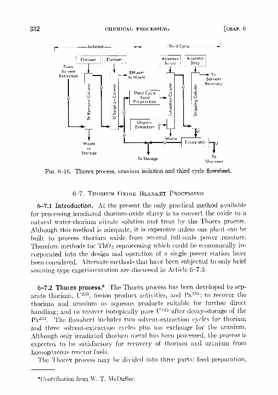
FIG. 6-16 . Thorex process, uranium isolation and third cycle flowsheet .
6-7. THORIUM OXIDE BLANKET PROCESSING
6-7.1 Introduction . At the present the only practical method availablefor processing irradiated thorium-oxide slurry is to convert the oxide to anatural water-thorium nitrate solution and treat by the Thorex process .
Although this method is adequate, it is expensive unless one plant can bebuilt to process thorium oxide from several full-scale power reactors .Therefore methods for Th02 reprocessing which could be economically in-
corporated into the design and operation of a single power station have
been considered. Alternate methods that have been subjected to only briefscouting-type experimentation are discussed in Article 6-7.3 .
6-7.2 Thorex process .* The Thorex process has been developed to sep-
arate thorium, U 233 , fission product activities, and Pa233 ; to recover thethorium and uranium as aqueous products suitable for further direct
handling; and to recover isotopically pure U233 after decay-storage of the
Pa233 The flowsheet includes two solvent-extraction cycles for thoriumand three solvent-extraction cycles plus ion exchange for the uranium .
Although only irradiated thorium metal has been processed, the process isexpected to be satisfactory for recovery of thorium and uranium from
homogeneous reactor fuels .The Thorex process may he divided into three parts : feed preparation,
*Contribution from «'. T. McDuffee .
solvent extraction, and product concentration and purification . Thesethree divisions are shown in Figs . 6-14, 6-15, and 6-16 .
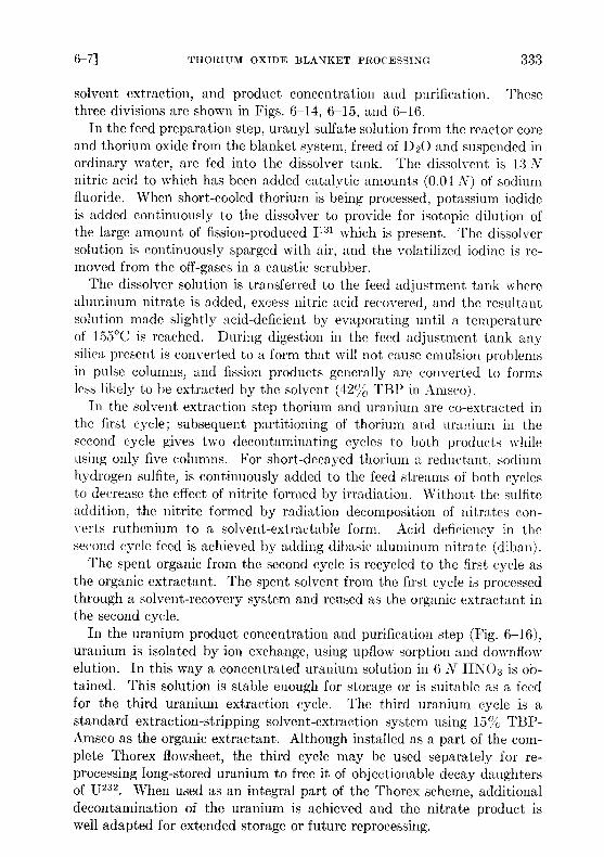
In the feed preparation step, uranyl sulfate solution from the reactor coreand thorium oxide from the blanket system, freed of D20 and suspended inordinary water, are fed into the dissolver tank . The dissolvent is 13 Nnitric acid to which has been added catalytic amounts (0 .04 N) of sodiumfluoride. When short-cooled thorium is being processed, potassium iodideis added continuously to the dissolver to provide for isotopic dilution ofthe large amount of fission-produced 11 31 which is present. The dissolversolution is continuously sparged with air, and the volatilized iodine is re-moved from the off-gases in a caustic scrubber .
The dissolver solution is transferred to the feed adjustment tank wherealuminum nitrate is added, excess nitric acid recovered, and the resultantsolution made slightly acid-deficient by evaporating until a temperatureof 155°C is reached . During digestion in the feed adjustment tank anysilica present is converted to a form that will not cause emulsion problemsin pulse columns, and fission products generally are converted to formsless likely to be extracted by the solvent (42%0 TBP in Amsco) .
In the solvent extraction step thorium and uranium are co-extracted inthe first cycle; subsequent partitioning of thorium and uranium in thesecond cycle gives two decontaminating cycles to both products whileusing only five columns . For short-decayed thorium a reductant, sodiumhydrogen sulfite, is continuously added to the feed streams of both cyclesto decrease the effect of nitrite formed by irradiation . Without the sulfiteaddition, the nitrite formed by radiation decomposition of nitrates con-verts ruthenium to a solvent-extractable form . Acid deficiency in thesecond cycle feed is achieved by adding dibasic aluminum nitrate (diban) .
The spent organic from the second cycle is recycled to the first cycle asthe organic extractant . The spent solvent from the first cycle is processedthrough a solvent-recovery system and reused as the organic extractant inthe second cycle .
In the uranium product concentration and purification step (Fig . 6-16),
uranium is isolated by ion exchange, using upflow sorption and downflowelution. In this way a concentrated uranium solution in 6 N HN03 is ob-tained . This solution is stable enough for storage or is suitable as a feedfor the third uranium extraction cycle . The third uranium cycle is astandard extraction-stripping solvent-extraction system using 15% TBP-Amsco as the organic extractant. Although installed as a part of the com-plete Thorex flowsheet, the third cycle may be used separately for re-processing long-stored uranium to free it of objectionable decay daughtersof U232 . When used as an integral part of the Thorex scheme, additionaldecontamination of the uranium is achieved and the nitrate product iswell adapted for extended storage or future reprocessing .

TABLE 6-10
AVERAGE DECONTAMINATION FACTORS FOR THORIUM AND URANIUM PRODUCTSIN THE THOREX PILOT PLANT
Thorium irradiated to 3500one additional
grams of mass-233uranium
percycle
ton, two completefor material
cyclesdecayed only
for both uranium and30 days .
thorium,
Decontamination factors
Gross Pa Ru Zr-A b Total rare earths I
Thorium400 days decayed 1 x 10 5 1 x 10 4 4 x 10³ 3 x 10 5 2 x 10630 days decayed 4 x 10 4 7 x 10 6 200 3 x 10 4 2 x 10⁶ 9 x 10⁸
Uranium-233400 days decayed 3 x 10° 3 x 10 5 2 x 10⁵ 8 x 10 .5 9 x 10 830 days decayed 5 x 10' 5 x 10 10 4 x 100 7 x 10 6 3 x 10 8 3 x 10 7
For return to an aqueous homogeneous reactor the decontaminateduranium would probably be precipitated as the peroxide, washed free ofnitrate, and then dissolved in D2SO4 and D20 . Product thorium wouldbe converted to thorium oxide by methods described in Section 4-3 .The adaptability of the Thorex flowsheet just described to processing
thorium irradiated to contain larger amounts of U233 per ton and decayeda short time has been demonstrated in the Thorex Pilot Plant at Oak RidgeNational Laboratory [22]. Fifteen hundred pounds of thorium irradiatedto 3500 grams of U233 per ton and decayed 30 days was processed throughtwo thorium cycles and three uranium cycles . The decontamination fac-tors for various elements achieved with short-decayed material are com-pared in Table 6-10 with results obtained with longer-decayed material .While the decontamination factors obtained with the short-decayed ma-terial compare favorably with the factors for the long-decayed material,the initial activity in the short-decayed thorium was 1000 times greaterthan in the long-decayed . Therefore, while the thorium and uraniumproducts did not meet tentative specifications after two complete cycles,the uranium product did meet those specifications after the third uraniumcycle. Since the chemical operations necessary to convert these materialsto forms suitable for use in a homogeneous reactor can be carried out re-motely, the products are satisfactory for return to a homogeneous reactorafter two cycles .
6-7.3 Alternate processing method .* Attempts to leach protactiniumand uranium produced in Th02 particles by neutron irradiation [23] in-dicate that both are rather uniformly distributed throughout the mass ofthe Th02 particle, and migration of such ions at temperatures up to 300 °Cis extremely slow . Since calculations show that the recoil energy of frag-ments from 15 233 fission is sufficiently large to eject most of them from aparticle of Th02 not larger than 10 microns in diameter, this offers thepossibility of separating fission and corrosion products from a slurry ofTh02 without destroying the oxide particles . Such a separation, however,depends on the ability to remove the elements that are subsequently ad-sorbed on the surface of the Th02 . Adsorption of various cations on Th02and methods for their removal are discussed in the following paragraphs .
Trace quantities of such nuclides as Zr 95 Nd 147 Y91 , and Ru103 whenadded to a slurry of Th02 in water at 250 °C are rapidly adsorbed on theoxide particles, leaving less than 10-4% of the nuclides in solution . Thetracer thus adsorbed cannot be eluted with hot dilute nitric or sulfuric acid .The adsorption of macroscopic amounts of uranium or neodymium onTh02 at 250°C is less for oxide fired to 1600 °C than for 650°C-fired oxide,
*Contribution from R . E. Leuze .
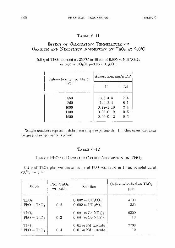
TABLE 6-11
EFFECT OF CALCINATION TEMPERATURE ONURANIUM AND NEODYMIUM ADSORPTION ON TH02 AT 250°C
0.5 g of Th02 slurried at 250°C in 10 ml of 0 .005 m Nd(N03)3or 0.05 m U02SO4-0 .05 m H2SO4 .
Calcination temperature,°C
Adsorption, mg/g
U
Th *
Nd
650 3 .3-4 .4 7 .4850 1 .9-2 .4 6 .11000 0 .72-1 .10 2.41100 0 .08-0 .19 0 .51600 0 .06-0 .12 0.3
*Single numbers represent data from single experiments . In other cases the rangefor several experiments is given .
TABLE 6-12
USE OF PB0 TO DECREASE CATION ADSORPTION ON TH02
0.2 g of Th02 plus various amounts of PbO coslurried in 10 ml of solution at250°C for 8 hr .
SolidsPbO/Th02wt. ratio Solution
Cation adsorbed on Th02,ppm
Th02 0 .002 m U02SO4 3100PbO + Th02 0 .2 0 .002 m U02SO4 220
Th02 0 .001 m Ce(N03)3 6200PbO + Th0 2 0 .2 0 .001 7n Ce(- 03)3 10
Th0 2 0 .01 ni Nd tartrate 2700PbO + Th02 0 .4 0 .01 m Nd tartrate 10
as illustrated in Table 6-11 . This change in amount of adsorption may bealmost entirely due to decrease in surface area of Th02 with increasedfiring temperature. The surface area of 1600 °C-fired Th02 is only 1 m 2/gTh02, while the 650°C-fired Th02 has a surface area of 35 m 2/g Th02 .
The cation adsorption on Th02 can be decreased by coslurrying someother oxide with the Th02. The added oxide must adsorb fission productsmuch more strongly than Th02 and be easily separable from Th02 . Theeffectiveness of PbO in decreasing cation adsorption on Th02 is shown inTable 6-12 . When Pb02 was used, more than 99% of the cations addedto the Th02-PbO slurry was adsorbed on the Pb02 . However, cationsadsorbed on Th02 were not transferred to Pb02 when it was added toslurry in which the cations were already adsorbed on the Th02 particles .Addition of dilute nitric acid to the Th02-PbO coslurry completely dis-solved the PbO and the cations adsorbed on it without disturbing the Th02 .
In all cases, cations adsorbed on Th02 at 250°C are so tightly held thatdilute nitric or sulfuric acid, even at boiling temperature, will not removethe adsorbed material . However, the adsorbed ions can be desorbed byrefluxing the Th02 in suitable reagents under such conditions that only asmall amount of 1600°C-fired Th02 is dissolved . Under the same treat-ment Th02 fired to only 650°C would be 90% dissolved .
REFERENCES
1 . A . T. GRESKY and E. D . ARNOLD, Poisoning of the Core of the Two-regionHomogeneous Thermal Breeder : Study No . l, USAEC Report ORNL CF-54-2-208,Oak Ridge National Laboratory, 1954 .
2 . E . D . ARNOLD and A. T. GRESKY, Relative Biological Hazards of RadiationsExpected in Homogeneous Reactors TBR and HPR, USAEC Report ORNTL-1982,Oak Ridge National Laboratory, 1955 .
3. R . A. MCNEES and S . PETERSON, in Homogeneous Reactor Project QuarterlyProgress Report for the Period Ending July 31, 1955, USAEC Report ORNL-1943,Oak Ridge National Laboratory, 1955 . (pp. 201-202)
4. D . E. FERGUSON et al ., in Homogeneous Reactor Project Quarterly ProgressReport for the Period Ending Apr . 30, 1956, USAEC Report ORNL-2096, OakRidge National Laboratory, 1956 . (p . 118)
5 . P. A . HAAS, Hydraulic Cyclones for Application to Homogeneous ReactorChemical Processing, USAEC Report ORNL-2301, Oak Ridge National Labora-tory, 1957 .
6. W. D. BURCH et al ., in Homogeneous Reactor Project Quarterly ProgressReport for the Period Ending July 31, 1957, USAEC Report ORNL-2379, OakRidge National Laboratory, 1957 . (p . 26)
7. R . A. McNEES et al., Oak Ridge National Laboratory, in HomogeneousReactor Project Quarterly Progress Report, USAEC Reports ORNL-2379, 1957(p. 137) ; ORNL-2432, 1957 (p. 147) ; ORNL-2493, 1958 .
8 . W. E . BROWNING and C . C . BOLTA, Measurement and Analysis of Holdupof Gas Mixtures by Charcoal Adsorption Traps, USAEC Report ORNL-2116,Oak Ridge National Laboratory, 1956 .
9. W. D . BURCH et al ., Oak Ridge National Laboratory, in HomogeneousReactor Project Quarterly Progress Report, USAEC Report ORNL-2432, 1957(p . 23) ; ORNL-2493, 1958 .
10 . P. H. HARLEY, HRT Mock-up Iodine Removal and Recombiner Tests,USAEC Report CF-58-1-138, Oak Ridge National Laboratory, 1958 .
11 . R . A. KEELER et al., Vitro Laboratories, 1957 . Unpublished .12. S. PETERSON, unpublished experiments .13. D . E. FERGUSON et al ., Oak Ridge National Laboratory, in Homogeneous
Reactor Project Quarterly Progress Report, USAEC Reports ORNL-2272, 1957(pp. 133-135) ; ORNL-2331, 1957 (pp. 142-143, 148-149) ; ORNL-2379, 1957(pp. 138-139) .
14. R. A . MCNEES et al ., in Homogeneous Reactor Project Quarterly ProgressReport for the Period Ending Apr . 30, 1955, USAEC Report ORNL-1895, OakRidge National Laboratory, 1955 . (pp. 175-176)
15. D . E. FERGUSON, Removal of Iodine from Homogeneous Reactors, USAECReport CF-56-2-81, Oak Ridge National Laboratory, 1956 ; Preliminary Designof an Iodine Removal System for a 460-Mw Thorium Breeder Reactor, USAECReport CF-56-7-12, Oak Ridge National Laboratory, 1956 .
16 . H . 0 . WEEREN, Preliminary Design of HRE-3 Iodine Removal System#1, USAEC Report CF-58-2-66 Oak Ridge National Laboratory, 1958 .
17 . S. PETERSON, Behavior of Iodine in the HRT, USAEC Report CF-58-3-75,Oak Ridge National Laboratory* 1958 .
18 . R. E . LEUZE et al., in Homogeneous Reactor Project Quarterly ProgressReport for the Period Ending Apr . 30, 1957, USAEC Report ORNL-2331, OakRidge National Laboratory, 1957 . (p . 151)
19 . R. E. CONNICK, in The Actinide Elements, National Nuclear Energy Series,Division IV, Volume 14A . New York: McGraw-Hill Book Co., Inc., 1954 .(pp. 221, 238-241)
20 . S . S. KIRSLis, Oak Ridge National Laboratory. Unpublished.21 . R. E. LEUZE and S. S . KIRSLTS, Oak Ridge National Laboratory, 1957 .
Unpublished .22. W. T. McDUFFEE and 0 . 0. YARBRO, Oak Ridge National Laboratory,
1958. Unpublished .23. D. E. FERGUSON et al ., in Homogeneous Reactor Project Quarterly Progress
Report for the Period Ending July 31, 1955, USAEC Report ORNL-1943, OakRidge National Laboratory, 1955. (p . 221)


![Chemical Problems of Non-Aqueous Fluid-Fuel Reactors [Disc 6] · 2018. 10. 1. · Aqueous Fluid-Fuel Reactors"; more general matters related to separation appear in Chapter IV of](https://static.fdocuments.in/doc/165x107/60b8afe2c563143e3256bbe0/chemical-problems-of-non-aqueous-fluid-fuel-reactors-disc-6-2018-10-1-aqueous.jpg)