
Fluid Dynamics Simulation in the Nuclear Industry - Ansys UK/staticassets/Fluid... · Fluid...
50
Fluid Dynamics Fluid Dynamics Simulation in the Simulation in the Nuclear Industry Nuclear Industry Fluid Dynamics Fluid Dynamics Simulation in the Simulation in the Nuclear Industry Nuclear Industry Phil Stopford Phil Stopford Phil Stopford Phil Stopford © 2011 ANSYS, Inc. All rights reserved. 1 ANSYS, Inc. Proprietary © 2011 ANSYS, Inc. All rights reserved. 1 ANSYS, Inc. Proprietary Phil Stopford Phil Stopford ANSYS UK ANSYS UK Phil Stopford Phil Stopford ANSYS UK ANSYS UK De Vere Milton Hill House 6 th April 2011
Transcript of Fluid Dynamics Simulation in the Nuclear Industry - Ansys UK/staticassets/Fluid... · Fluid...

Fluid Dynamics Fluid Dynamics Simulation in the Simulation in the Nuclear IndustryNuclear Industry
Fluid Dynamics Fluid Dynamics Simulation in the Simulation in the Nuclear IndustryNuclear Industry
Phil StopfordPhil StopfordPhil StopfordPhil Stopford
© 2011 ANSYS, Inc. All rights reserved. 1 ANSYS, Inc. Proprietary© 2011 ANSYS, Inc. All rights reserved. 1 ANSYS, Inc. Proprietary
Phil StopfordPhil Stopford
ANSYS UKANSYS UK
Phil StopfordPhil Stopford
ANSYS UKANSYS UK
De Vere Milton Hill House
6th April 2011

Contents
• Multiphase model validation
– Vertical and horizontal pipe flow
– Bubbly flow around obstacle
• Case studies
– Fuel assemblies
© 2011 ANSYS, Inc. All rights reserved. 2 ANSYS, Inc. Proprietary
– Fuel assemblies
– Pressure vessels
– Steam generators
– Safety systems
– Radwaste
• Conclusions

ValidationCFD Exp.
© 2011 ANSYS, Inc. All rights reserved. 3 ANSYS, Inc. Proprietary
CFD Exp.

Validation Test Cases
• Two-phase flows with lower
void fraction
– Vertically upward
– Vertically downward
– Horizontal, concurrent
– Horizontal countercurrent
• Free Surface Flows
– Horizontal concurrent
– Horizontal countercurrent
– Impinging Jets (Downcomer)
– Free Jets (ECCS)
• Flows with phase change
© 2011 ANSYS, Inc. All rights reserved. 4 ANSYS, Inc. Proprietary
– Horizontal countercurrent
• Two-phase flows with higher
void fraction
– Vertically upward
– Vertically downward
– Horizontal, concurrent
– Horizontal countercurrent
• Bubbly flow around obstacle
• Flows with phase change
– Condensation
– Evaporation
– Flashing
– Boiling

Vertical Pipe Flows
• Experiments
– FZR
– MTLoop & TOPFLOW
Facility
• Modeling & Validation
– FZR
© 2011 ANSYS, Inc. All rights reserved. 5 ANSYS, Inc. Proprietary
– FZR
– ANSYS CFX
• Target variables
– Volume fraction
– Gas velocity
– Water velocity
– Bubble size distributions

FZR-052
2.0
2.5
3.0
3.5
normalized volume fraction [-]
Experiment FZR-052
Antal W.L.F., Grid 2
Tomiyama W.L.F., Grid 2
Frank W.L.F., Grid 2
© 2011 ANSYS, Inc. All rights reserved. 6 ANSYS, Inc. Proprietary
0.0
0.5
1.0
1.5
2.0
0.00 5.00 10.00 15.00 20.00 25.00
Radius [mm]
normalized volume fraction [-]

FZR-096
2.0
2.5
3.0
3.5
normalized volume fraction [-]
Experiment FZR-096
Antal W.L.F., Grid 2
Tomiyama W.L.F., Grid 2
Frank W.L.F., Grid 2
© 2011 ANSYS, Inc. All rights reserved. 7 ANSYS, Inc. Proprietary
0.0
0.5
1.0
1.5
0.00 5.00 10.00 15.00 20.00 25.00
Radius [mm]
normalized volume fraction [-]

wire-mesh sensormovable diaphragm
movable diaphragm
TOPFLOW Test FacilityTOPFLOW Test Facility
© 2011 ANSYS, Inc. All rights reserved. 8 ANSYS, Inc. Proprietary
gas injection

3d Bubbly Flow Around Obstacle
• Streamlines around the
obstacle
– Vortex system around the
edge of the obstacle
– Velocity component from left
to right along the
© 2011 ANSYS, Inc. All rights reserved. 9 ANSYS, Inc. Proprietary
to right along the
vortex core
– Higher residence time in
vortex core close to the
straight edge

3d Bubbly Flow Around Obstacle
Water Velocity Comparison
• Comparison
CFD � Experiment
• Absolute water velocity
distribution in symmetry plane
• Import of exp. data
CFD Exp.
© 2011 ANSYS, Inc. All rights reserved. 10 ANSYS, Inc. Proprietary
• Import of exp. data
into CFX-Post
• Pre-interpolation of exp. data
to ∆z=0.01m

3d Bubbly Flow Around Obstacle
Air Void Fraction Comparison
• Comparison
CFD � Experiment
• Air void fraction
distribution in symmetry
plane
CFD Exp.
© 2011 ANSYS, Inc. All rights reserved. 11 ANSYS, Inc. Proprietary

Experimental Test Facilities
@ TU Munich
• Regular slug flow with defined inlet BC´s
Wire mesh sensor data
Air
time
© 2011 ANSYS, Inc. All rights reserved. 12 ANSYS, Inc. Proprietary
time
By courtesy of
Edurne Carpintiero, TD, TUM

Slug Flow Simulation -
Mass Flow Boundary Condition
• Sinusoidal free surface perturbation (initialization and inlet BC’s)
• Transient simulation of 7.0s real time
• Slug formation after ~4.0s at x~4.0m
• Stable slug propagation; slug front/tail are continuously changing
© 2011 ANSYS, Inc. All rights reserved. 13 ANSYS, Inc. Proprietary

Slug Flow Simulation -
Mass Flow BC’s (cont.)
First comparison with experimental data:
• Start of slug formation at ~4.0m from the inlet
• Difficult to reproduce experimental setup in CFD
– Inlet BC’s (e.g. phase mixing, inlet turbulence properties)
– Pressure outlet conditions (pipes & tanks downstream of test section)
• Quantitative comparison difficult for strong transient flow
– Small number of computed slugs
© 2011 ANSYS, Inc. All rights reserved. 14 ANSYS, Inc. Proprietary
– Small number of computed slugs
– Slug length affected by limited pipe length and/or inlet conditions
numerical simulation experiment
slug period ~2.7m ~1.8m
slug transition velocity ~3.0 m/s ~2.7 m/s
pressure loss ~2000 - 2800 Pa on the last
4m, 2 slugs
� ~500 - 700 Pa/m
(strong transient)
~700 Pa/m

The Bartolomej Test Case
R = 7.7 mm
q=0.57MW/m
2
Variable Value
P 4.5MPa
R 7.7 mm
© 2011 ANSYS, Inc. All rights reserved. 15 ANSYS, Inc. Proprietary
Z= 2 m
q=0.57MW/m
Gin=900 kg/(s m2)
R 7.7 mm
Gin 900 kg/(s m2)
0.57MW/m2
Subcooling 58.2 K
q&

Comparison to Experimental Data
© 2011 ANSYS, Inc. All rights reserved. 16 ANSYS, Inc. Proprietary

Fuel Assemblies
© 2011 ANSYS, Inc. All rights reserved. 17 ANSYS, Inc. Proprietary

Wall Boiling in a 3x3 Periodic
Fuel Rod Bundle
• 3×3 rod periodic section from a nuclear
reactor fuel assembly with guide vanes
• Periodic BC’s at all sides
• Wall heat flux of
qwall = 500 kW/m2
• Reference Pressure
© 2011 ANSYS, Inc. All rights reserved. 18 ANSYS, Inc. Proprietary
• Reference Pressure
p = 15.7 MPa
• Water inlet velocity
vInlet=5.0m/s
• Water inlet temperature
TInlet= 607K
(= 12K water subcooling)

Wall Boiling in a 3x3 Periodic
Geometry & Meshing
• Geometry preparation in ANSYS Design Modeler
• Extraction of periodic fluid domain
© 2011 ANSYS, Inc. All rights reserved. 19 ANSYS, Inc. Proprietary

Wall Boiling in a 3x3 Periodic
Geometry & Meshing
• Meshing in ANSYS Workbench
• Tet/Prism in lower part
• Extruded prism mesh in
upper part
© 2011 ANSYS, Inc. All rights reserved. 20 ANSYS, Inc. Proprietary
upper part
• Mesh statistic
– Tetra: 1,752,320
– Hexa: 838,800
– Prism: 2,088,820

Wall Boiling in a 3x3 Periodic
Fuel Rod Bundle
© 2011 ANSYS, Inc. All rights reserved. 21 ANSYS, Inc. Proprietary
Vapour volume
fraction on
horizontal planes

Wall Boiling in a 3x3 Periodic
Fuel Rod Bundle
© 2011 ANSYS, Inc. All rights reserved. 22 ANSYS, Inc. Proprietary
Near wall
water
temperature

Wall Boiling in a 3x3 Periodic
Fuel Rod Bundle
© 2011 ANSYS, Inc. All rights reserved. 23 ANSYS, Inc. Proprietary
Streamlines &
water velocity in
horizontal planes
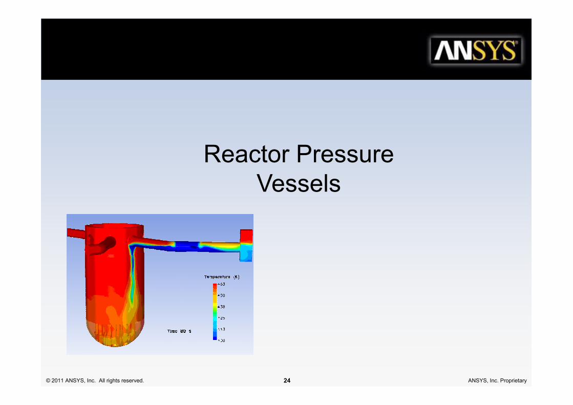
Reactor Pressure
Vessels
© 2011 ANSYS, Inc. All rights reserved. 24 ANSYS, Inc. Proprietary

VVER-1000 Pressure Vessel Model
© 2011 ANSYS, Inc. All rights reserved. 25 ANSYS, Inc. Proprietary
Courtesy of M. Böttcher, Institute of Reactor Safety (IRS)
Forschungszentrum Karlsruhe - KIT

RPV model – lower plenum
Flow through the perforated upper support columns:
© 2011 ANSYS, Inc. All rights reserved. 26 ANSYS, Inc. Proprietary
Pressure loss obtained from a standalone full
detail model (3 Mio cells / column)Implementation of a pressure loss coefficient
in the coarser RPV model (5000 cells /
column)

Temperature Distribution and Flow
Patterns from the Loop Model
© 2011 ANSYS, Inc. All rights reserved. 27 ANSYS, Inc. Proprietary

Influences on Mixing Coefficients
© 2011 ANSYS, Inc. All rights reserved. 28 ANSYS, Inc. Proprietary
Swirl
Suppression
Asymmetric flow conditions at the RPV inlet affect the coolant mixing process !
The inlet conditions from the RPV models have to be revised.

Validation Case
• FZ Karlsruhe (Böttcher)
• VVER 1000– Unit 6, Kozloduy, Bulgaria
– OECD benchmark
• Geometry model
© 2011 ANSYS, Inc. All rights reserved. 29 ANSYS, Inc. Proprietary
• Geometry model– Downcomer & core
– Upper & lower plenum
• Mesh– 13 million elements
• Simulation• ANSYS CFX & HPC
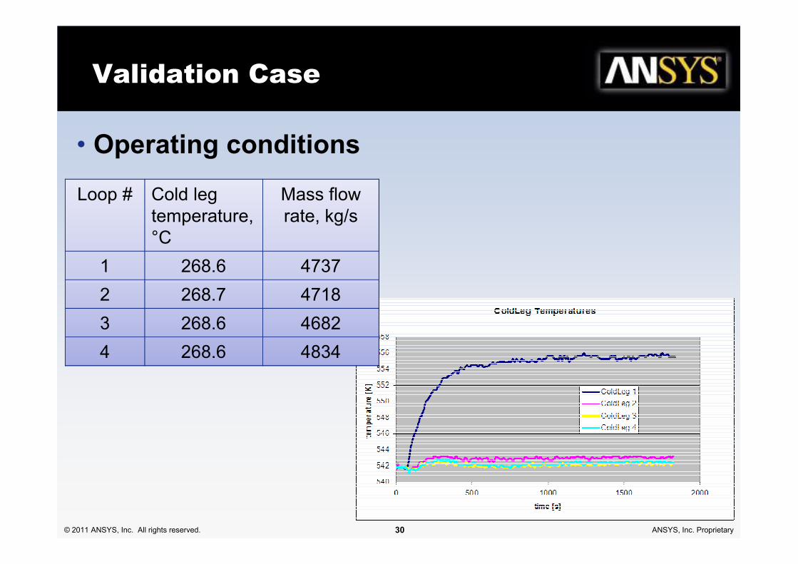
Validation Case
• Operating conditions
Loop # Cold leg
temperature,
°C
Mass flow
rate, kg/s
1 268.6 4737
© 2011 ANSYS, Inc. All rights reserved. 30 ANSYS, Inc. Proprietary
2 268.7 4718
3 268.6 4682
4 268.6 4834

Validation Case
• Temperatures @ core exit
© 2011 ANSYS, Inc. All rights reserved. 31 ANSYS, Inc. Proprietary

Steam
Generators
© 2011 ANSYS, Inc. All rights reserved. 32 ANSYS, Inc. Proprietary

Design of Nuclear Steam Generator
• Duke Energy's nuclear power plant at
Oconee, South Carolina
• Babcock & Wilcox (Canada) unique
once-through steam generator
© 2011 ANSYS, Inc. All rights reserved. 33 ANSYS, Inc. Proprietary
• Secondary-loop water is converted into
dry superheated steam
• Restrictor (7 venturis) added to outlets
• Need to check maximum ∆p

Design of Nuclear Steam Generator
Flow uniformly distributed
© 2011 ANSYS, Inc. All rights reserved. 34 ANSYS, Inc. Proprietary

Design of Nuclear Steam
Generator
Pressure Velocity
© 2011 ANSYS, Inc. All rights reserved. 35 ANSYS, Inc. Proprietary
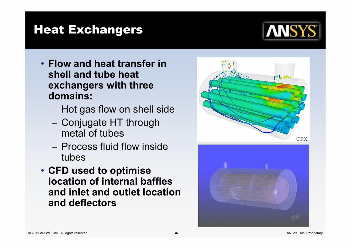
Heat Exchangers
• Flow and heat transfer in shell and tube heat exchangers with three domains:
– Hot gas flow on shell side
– Conjugate HT through
© 2011 ANSYS, Inc. All rights reserved. 36 ANSYS, Inc. Proprietary
– Conjugate HT through metal of tubes
– Process fluid flow inside tubes
• CFD used to optimise location of internal baffles and inlet and outlet location and deflectors

Porous Media HE Model
• Tube bundle geometry is often too
complex to model explicitly
• Represent shell-and-tube heat
exchanger by a porous domain
• Add 1-D additional variables to
represent the temperature and flow
Pressure Tube Temperature
© 2011 ANSYS, Inc. All rights reserved. 37 ANSYS, Inc. Proprietary
represent the temperature and flow
velocity in the tubes
• Eulerian multiphase bulk boiling
model to predict steam production
• Add-on module to CFX
Steam Mass Fraction Shell Temperature
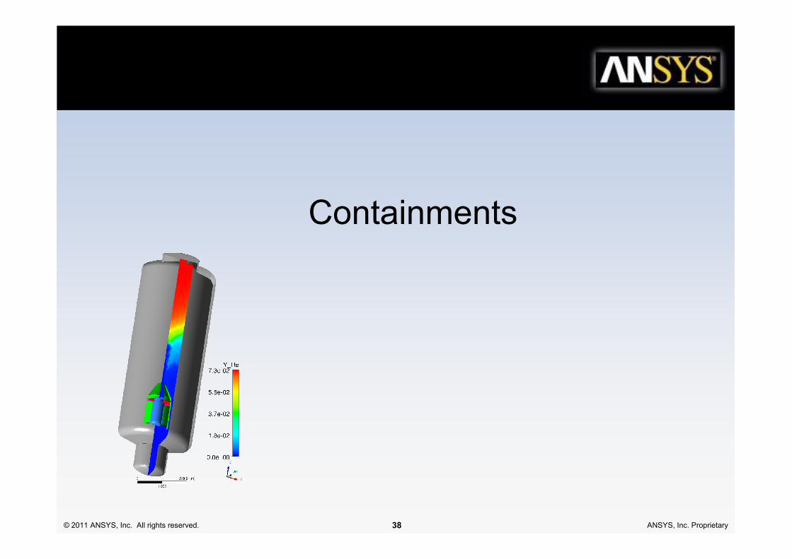
Containments
© 2011 ANSYS, Inc. All rights reserved. 38 ANSYS, Inc. Proprietary
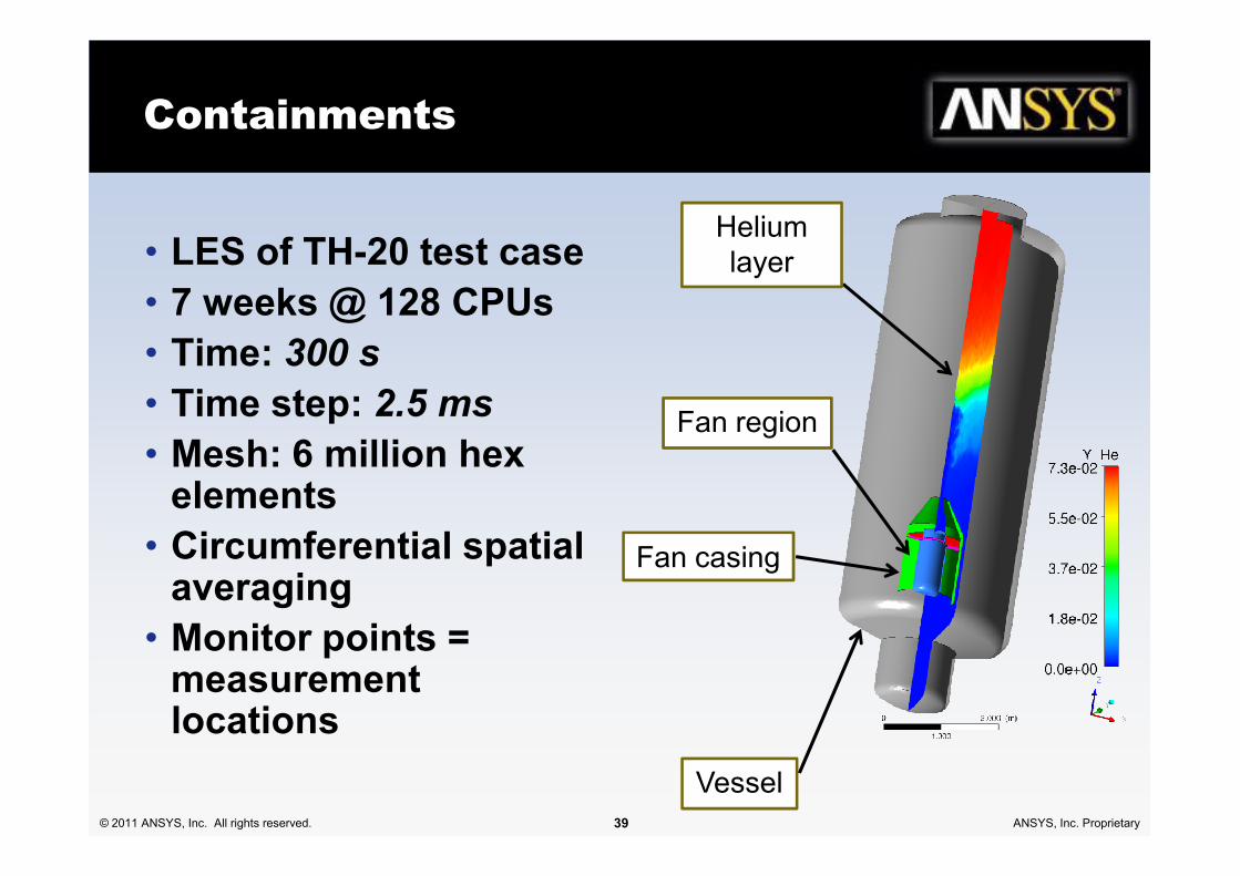
Containments
• LES of TH-20 test case
• 7 weeks @ 128 CPUs
• Time: 300 s
• Time step: 2.5 ms
• Mesh: 6 million hex Fan region
Helium
layer
© 2011 ANSYS, Inc. All rights reserved. 39 ANSYS, Inc. Proprietary
• Mesh: 6 million hex elements
• Circumferential spatial averaging
• Monitor points = measurement locations
Fan casing
Fan region
Vessel

Containments
© 2011 ANSYS, Inc. All rights reserved. 40 ANSYS, Inc. Proprietary

Containments
© 2011 ANSYS, Inc. All rights reserved. 41 ANSYS, Inc. Proprietary

Safety
Systems
© 2011 ANSYS, Inc. All rights reserved. 42 ANSYS, Inc. Proprietary
Vapor volume
fraction for a
simplified
Westinghouse
AP600 In-
Containment
Refueling
Water Storage
Tank
Courtesy Technical University of Aachen and
Center for Multiphase Research, RPI

Passive Safety Systems
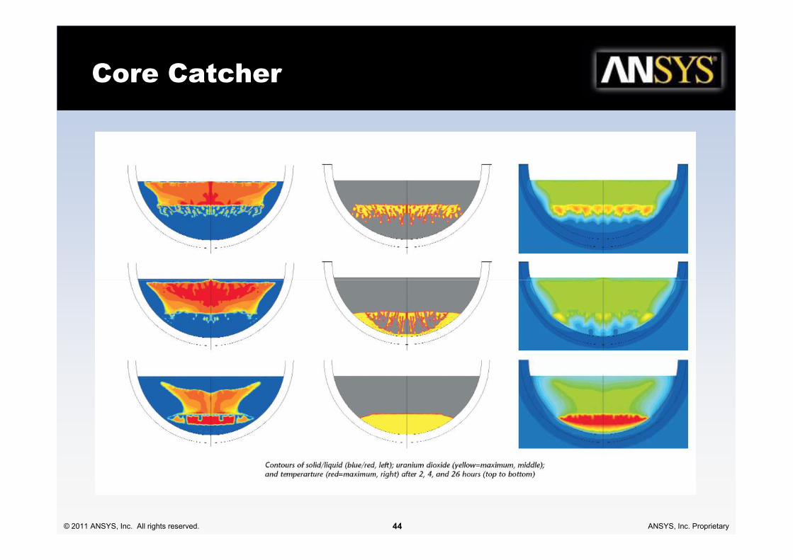
Core Catcher:
• Hemisphere filled with steel
• Catches molten core
• Steel melts, then covers uranium
dioxide core material
• CFD shows progression of
fluid mechanics, phase
change, and heat transfer.
© 2011 ANSYS, Inc. All rights reserved. 43 ANSYS, Inc. Proprietary
change, and heat transfer.
Courtesy Technical University of Aachen and
Center for Multiphase Research, RPI
Vapor volume
fraction for a
simplified
Westinghouse
AP600 In-
Containment
Refueling
Water Storage
Tank
Benefits of CAE
– Gain physical insight about flow structures to guide safety system design
– Generate new parametric relationships to embed in system-level tools
– Extend behavior prediction from experimental to full scale conditions
Core Catcher
© 2011 ANSYS, Inc. All rights reserved. 44 ANSYS, Inc. Proprietary

Deflagration/Explosion
© 2011 ANSYS, Inc. All rights reserved. 45 ANSYS, Inc. Proprietary

Radwaste Storage
© 2011 ANSYS, Inc. All rights reserved. 46 ANSYS, Inc. Proprietary
Courtesy Technical University of Aachen and
Center for Multiphase Research, RPI
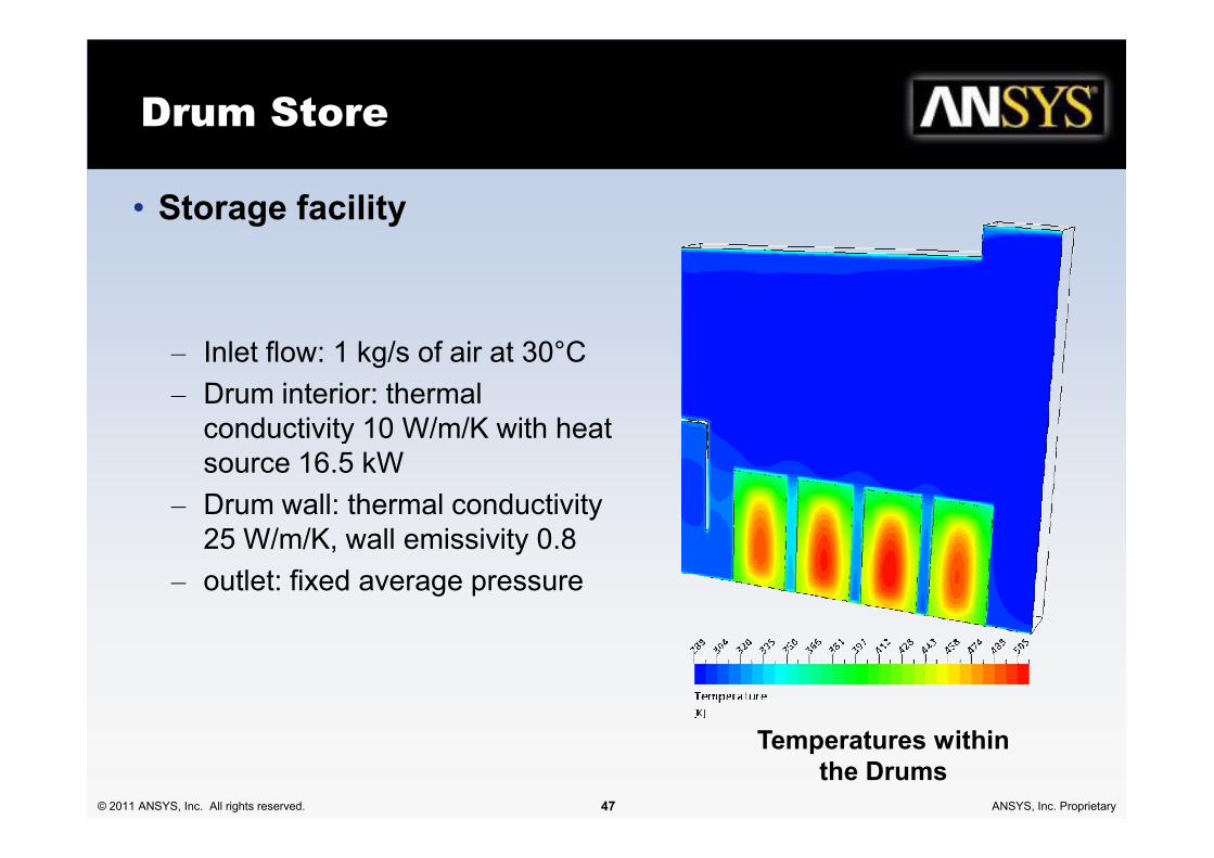
Drum Store
• Storage facility
– Inlet flow: 1 kg/s of air at 30°C
– Drum interior: thermal
conductivity 10 W/m/K with heat
© 2011 ANSYS, Inc. All rights reserved. 47 ANSYS, Inc. Proprietary
conductivity 10 W/m/K with heat
source 16.5 kW
– Drum wall: thermal conductivity
25 W/m/K, wall emissivity 0.8
– outlet: fixed average pressure
Temperatures within
the Drums

Drum Storage Ventilation:
Inlet
Outlet
© 2011 ANSYS, Inc. All rights reserved. 48 ANSYS, Inc. Proprietary
Temperature
Inlet
Flow
Diffuser
Symmetry
plane
Velocity

Dispersion: Hydrogen Build Up
Hydrogen build up in a
vault store with only
passive ventilation
© 2011 ANSYS, Inc. All rights reserved. 49 ANSYS, Inc. Proprietary
Summary
• ANSYS CFD has well-validated turbulence and multi-
phase models suitable for nuclear industry
applications
• Both FLUENT and CFX were originally written with
nuclear industry applications in mind
© 2011 ANSYS, Inc. All rights reserved. 50 ANSYS, Inc. Proprietary
• Long history of successful modelling cases
• Range of applications includes fuel assemblies,
primary and secondary circuit flows, containments,
safety and radwaste storage


