Fluid characteristic of multiphase fluid in annular space ...
15
ARTICLE J. Cent. South Univ. (2019) 26: 1327−1341 DOI: https://doi.org/10.1007/s11771-019-4090-y Fluid characteristic of multiphase fluid in annular space between pump barrel and plunger XING Ming-ming(邢明明) 1, 2 , ZHOU Li-li(周丽丽) 2, 3 , ZHAO Yan(赵妍) 1, 2 , XUE Kai-feng(薛凯峰) 1, 2 , ZHANG Cheng-mao(张成茂) 1, 2 1. School of Mechanical & Vehicle Engineering, Linyi University, Linyi 276000, China; 2. Municipal Modern Agriculture UAV Engineering and Technological Research Centers, Linyi 276000, China; 3. School of Chemistry & Chemical Engineering, Linyi University, Linyi 276000, China © Central South University Press and Springer-Verlag GmbH Germany, part of Springer Nature 2019 Abstract: The pump performance parameters, such as pump pressure, plunger friction and pump valve resistance, are fundamental parameters of optimal design of pump efficiency and sucker rod pumping system (SRPS). In this paper, considering the characteristic of geometrical nonlinear and rheology property of multiphase fluid, the pump performance parameters are studied. Firstly, a dynamics model of annular fluid flow is built. In the detail, a partial differential equation of annular fluid is established and a computing model of fluid pressure gradient is built. Secondly, the simulation models of plunger friction and hydraulic resistance of pump valve are built. Finally, a novel simulation method of fluid pressure in annular space is proposed with software ANSYS. In order to check up the correction of models proposed in this paper, the comparison curves of experiment and simulation results are given. Based on above model, the whole simulation model of plunger pump is simulated with Visual Basic 6.0. The results show that the fluid friction of pump plunger and instantaneous resistance of pump valve are nonlinear. The impact factors of pump performance parameters are analyzed, and their characteristic curves are given, which can help to optimize the pump motion parameters and pump structural. Key words: sucker rod pumping system (SRPS); pump; pump plunger; pump barrel; performance parameter Cite this article as: XING Ming-ming, ZHOU Li-li, ZHAO Yan, XUE Kai-feng, ZHANG Cheng-mao. Fluid characteristic of multiphase fluid in annular space between pump barrel and plunger [J]. Journal of Central South University, 2019, 26(5): 1327–1341. DOI: https://doi.org/10.1007/s11771-019-4090-y. 1 Introduction The sucker rod pumping system is by far the predominant artificial lift system used in the world for producing oil well [1–3]. Sucker rod pumping system (SRPS) is made up of three parts, surface driving unit, rod-tube string and pump. The three-dimensional map of SRPS is shown in Figure 1. The experimental and research results indicate that the pump efficiency has significant impact on the overall efficiency of SRPS [4, 5]. Based on the measured data of an oil production plant in Daqing oil field, the efficiency curves of then oil wells are given in Figure 2. The results show that the pump efficiency is an important Foundation item: Projects(ZR2017LEE002, ZR2016HB59) supported by the Natural Science Foundation of Shandong Province, China; Project(LYDX2016BS032) supported by the Scientific Research Starting Foundation of Linyi University, China; Project(2017YF012) supported by Shandong Agricultural Machinery Equipment Research and Development Innovation, China; Projects(201801219003, 201802026003) supported by Collaborative Education Project of Industry-Education Cooperation of National Education Ministry, China Received date: 2018-09-06; Accepted date: 2019-03-10 Corresponding author: XING Ming-ming, PhD, Lecturer; Tel: +86-539-7258833; E-mail: [email protected]; ORCID: 0000-0003-1785-2835
Transcript of Fluid characteristic of multiphase fluid in annular space ...
ARTICLE J. Cent. South Univ. (2019) 26: 1327−1341 DOI: https://doi.org/10.1007/s11771-019-4090-y
Fluid characteristic of multiphase fluid in annular space between pump barrel and plunger
XING Ming-ming(邢明明)1, 2, ZHOU Li-li(周丽丽)2, 3, ZHAO Yan(赵妍)1, 2, XUE Kai-feng(薛凯峰)1, 2, ZHANG Cheng-mao(张成茂)1, 2
1. School of Mechanical & Vehicle Engineering, Linyi University, Linyi 276000, China; 2. Municipal Modern Agriculture UAV Engineering and Technological Research Centers,
Linyi 276000, China; 3. School of Chemistry & Chemical Engineering, Linyi University, Linyi 276000, China
© Central South University Press and Springer-Verlag GmbH Germany, part of Springer Nature 2019
Abstract: The pump performance parameters, such as pump pressure, plunger friction and pump valve resistance, are fundamental parameters of optimal design of pump efficiency and sucker rod pumping system (SRPS). In this paper, considering the characteristic of geometrical nonlinear and rheology property of multiphase fluid, the pump performance parameters are studied. Firstly, a dynamics model of annular fluid flow is built. In the detail, a partial differential equation of annular fluid is established and a computing model of fluid pressure gradient is built. Secondly, the simulation models of plunger friction and hydraulic resistance of pump valve are built. Finally, a novel simulation method of fluid pressure in annular space is proposed with software ANSYS. In order to check up the correction of models proposed in this paper, the comparison curves of experiment and simulation results are given. Based on above model, the whole simulation model of plunger pump is simulated with Visual Basic 6.0. The results show that the fluid friction of pump plunger and instantaneous resistance of pump valve are nonlinear. The impact factors of pump performance parameters are analyzed, and their characteristic curves are given, which can help to optimize the pump motion parameters and pump structural. Key words: sucker rod pumping system (SRPS); pump; pump plunger; pump barrel; performance parameter Cite this article as: XING Ming-ming, ZHOU Li-li, ZHAO Yan, XUE Kai-feng, ZHANG Cheng-mao. Fluid characteristic of multiphase fluid in annular space between pump barrel and plunger [J]. Journal of Central South University, 2019, 26(5): 1327–1341. DOI: https://doi.org/10.1007/s11771-019-4090-y.
1 Introduction
The sucker rod pumping system is by far the predominant artificial lift system used in the world for producing oil well [1–3]. Sucker rod pumping system (SRPS) is made up of three parts, surface driving unit, rod-tube string and pump. The
three-dimensional map of SRPS is shown in Figure 1. The experimental and research results indicate that the pump efficiency has significant impact on the overall efficiency of SRPS [4, 5]. Based on the measured data of an oil production plant in Daqing oil field, the efficiency curves of then oil wells are given in Figure 2. The results show that the pump efficiency is an important
Foundation item: Projects(ZR2017LEE002, ZR2016HB59) supported by the Natural Science Foundation of Shandong Province, China;
Project(LYDX2016BS032) supported by the Scientific Research Starting Foundation of Linyi University, China; Project(2017YF012) supported by Shandong Agricultural Machinery Equipment Research and Development Innovation, China; Projects(201801219003, 201802026003) supported by Collaborative Education Project of Industry-Education Cooperation of National Education Ministry, China
Received date: 2018-09-06; Accepted date: 2019-03-10 Corresponding author: XING Ming-ming, PhD, Lecturer; Tel: +86-539-7258833; E-mail: [email protected]; ORCID:
0000-0003-1785-2835

J. Cent. South Univ. (2019) 26: 1327–1341
1328
Figure 1 Structure schematic map of SRPS
Figure 2 Unit and system efficiency of SRPS
parameter which reduces system efficiency. In Figure 2, it is an especial point when the well number is 4.
The pump efficiency is higher than others. The reason of high pump efficiency is that the moisture content of the well is high. Because the pump cylinder is filled with enough liquid, the big diameter and long stroke are major factors behind high pump efficiency. In order to get high efficiency, the different wells are designed with different pumps. For example, the double-acting pump is used for high flow-rate [6]; the anti-gas pump is used for wells of high oil ratio [7] and the hydraulic feedback pump is designed for heavy oil well [8]. Given the above, the research of pump is increasingly attracting the attention of experts and researchers in the world [9–11]. The characteristic research of multiphase fluid in the pump is
foundation for the design of pump efficiency and the optimal design of SRPS. Usually, with the research of fluid characteristic in the pump, it is taken as flow problem of a vertical pipe. In the current, three methods for predicting flow pattern are usually used, such as Oriszewski method [12], Beggs-Brill method [13] and Hasan-Kabir method [14]. On the basis of the Hasan-Kabir method, the simulation model of discharge pressure is given by DONG [15]. With the Oriszewski method, the model of pressure distribution in the casing is given by DONG et al [16]. However, the fluid flow regularity of annular space between pump barrel and plunger is not given, which affects the pump efficiency [17, 18]. WANG et al [19] set up a new model to evaluate polished rod load of SRPS, but they gave a simple model of fluid flow regularity of annular space with single phase flow. Then an improved model of plunger load is built, considering the influence of hydraulic loss and clearance leakage. TANG et al [20] proposed a novel vacuum ice slurry producing system with jet-pumps to deal with the problems of high energy consumption and ice blockage. BAKHTIZIN [21] studied the influence of regular microrelief forms on fluid leakage through plunger pair of sucker rod pump. And practical recommendations on the choice of geometrical parameters of grooves in which there is maximum hydraulic resistance for the flow of fluid in the gap plunger pair of sucker rod pump have been developed. HULSURKAR et al [22] made an experiment study, providing laboratory data/models that can support the characterization of the pressure drop and flow patterns experienced in horizontal wells completed using the process of cold heavy-oil production with sand and other viscous-oil-producing wells. The effects of unsteady flow characteristics on solid-liquid two-phase flow and pump performance are researched under design condition by WU et al [23]. CHAO et al [24] analyzed oil–water two- phase flow patterns in a horizontal pipe with a 16-electrode electrical resistance tomography (ERT) system.
According to the analyses above, the performance parameters of pump have been studied, such as pump efficiency, hydraulic loss or clearance leakage. However, considering the influence of dynamic characteristics of multiphase fluid on the

J. Cent. South Univ. (2019) 26: 1327–1341
1329
plunger friction and pump efficiency [17], the characteristic of annular multiphase fluid needs to be improved. In this paper, considering the characteristic of geometrical nonlinear and rheology property of multiphase fluid, a new dynamics model of annular fluid flow is built in Section 2. In the detail, considering the influence of plunger eccentric and buckling behavior, a partial differential equation of annular fluid is established. Considering the multiphase fluid characteristic and differential pressure of the gravity and friction, a computing model of fluid pressure gradient is built with Orkiszewski method [12]. Based on above models, considering hydraulic loss and friction loss, the simulation models of plunger friction and hydraulic resistance of pump valve are built. In Section 3, in order to check up the correction of simulation model proposed in this paper, comparison experiments are given. The results show that the simulation curves are found to be in good agreement with experimental curve. In Section 4, a novel calculation method of annulus fluid with software ANSYS is given. The computational methods of pressure gradient, fluid pressure, plunger friction, valve resistance and characteristic analysis are given. The simulation results provide theoretic foundation for optimal design and pump efficiency in special well. 2 Mechanical model of pump barrel and
plunger
Considering the force-deformation of plunger, the structural model of pump barrel and plunger is shown in Figure 3, and the basic parameters are given in Table 1. The circle O2 is defined as center point of pump barrel, and the circle O1 is defined as center point of pump plunger.
Based on Figure 3, the gap between pump barrel and plunger is derived as follows:
cos cosr e R r (1)
where δr is gap between pump barrel and plunger, m; e is absolute eccentric distance, m; θ is relative rotation angle, rad; R is radius of plunger, m; r is radius of pump barrel, m; β is arbitrary eccentric angle, rad.
When e is very small, β is close to zero, and cosβ≈1. In the meantime, ε=e/Δr, Δr=R–r. The Eq. (1) is derived as follows:
Figure 3 Structural model of pump barrel and plunger
Table 1 Basic parameters of pump barrel and plunger
Item Value
Outside diameter of pump barrel/mm 0.073
Intside diameter of pump barrel/m 0.056
Outside diameter of pump plunger/m 0.0559
Eccentric distance/m 0.0001
Gas density/(kgꞏm–3) 1.29
Water density/(kgꞏm–3) 1000
Plunger length/m 1.0
Volume factor of oil 1.08
Volume factor of water 1.0
Gas deviation factor 0.89
1 cosr r (2)
where ε is dimensionless number; Δr is concentric radial height, m.
The annulus liquid is defined as non- Newtonian power law fluid. And the fluid is quite steady flow state. Then ux=uy=0, uz=up, ∂ux/∂t= ∂uy/∂t=∂uz/∂t=0. Based on the Navier-Stokes equations, the equations of fluid velocity in the annular space are given.
l
l
2 2 2
2 2 2l
10
10
1p p p ppz
p
x
p
y
u u u u pu g
z zx y z
(3)
where p is axial pressure, Pa; ρl is density of fluid,
J. Cent. South Univ. (2019) 26: 1327–1341
1330
kg/m3; κ is kinematic viscosity, m2/s; g is gravitational acceleration, m/s2.
When y-axial pressure and x-axial pressure are constant, ∂p/∂x=0, ∂p/∂y=0, ∂up/∂y=0, ∂2up/∂y2=0. In the same cross-section, ∂up/∂z=0, ∂2up/∂z2=0. The differential equation will be described as follows:
2
d c o d d2l
1pug p p L H
x
(4)
The computed formula of pump discharge
pressure is given as follows:
d
d o 0
dd
d
L pp p z
z (5)
where po is the wellhead oil pressure, Pa; pd is pump discharge pressure, Pa; pc is wellhead casing pressure, Pa; Ld is pump depth, m; Hd is dynamic fluid level, m.
The flow pattern plays an essential role in the field of multiphase flow measurement [25]. With Orkiszewski method, the equations of pressure gradient of multiphase fluid are given.
When qg/qt<LB,
2
l lg l g g
p g
d1
d 4 1
qpH H g f
z r A H
(6a)
When qg/qt>LB, vg′<LB,
2
l s p l ll
s p p g
d
d 4 1
t
t
W v A qpg f
z q v A r A H
(6b)
When LM>vg′> LB,
0.750.25l l
SLp
d75 84
d
qpg
z A g
0.25g SL l
p
0.750.25 0.25l l l l
p p
25 84 36
q g
A g
q q
A g A g
0.750.25 0.25SLl l l
SLp p
0.750.25 0.25l l l l
p p
75 84
25 84 36
gq
A g A g
q q
A g A g
0.25 0.25g Mi l l Mi l
p p
10.750.254l l l l
p p
50 36
25 84 36
q g q g
A g A g
q q
A g A g
0.25 0.25g Mi l l Mi l
p p
10.750.254l l l l
p p
50 36
25 84 36
q q
A g A g
q q
A g A g
(6c)
When vg′>LM,
2g g g g
l gl g l g p
d1
d 4
q q qpg g f
z q q q q r A
(6d) where
2g
gs p s p s p
411 1
2t t
qq qH
v A v A v A
(7)
ρg is gas density, kg/m3; f is frictional damping coefficient; vs is slippage velocity, m/s; qt is volume flow of liquid, m3/s; qg is volume flow of gas, m3/s; LB is boundary of bubble flow; v'g is non- dimensional flow rate of gas; LM is boundary of mist flow; Ap is cross-sectional area of eccentric annulus, m2; wt is total mass flow of liquid, kg/s; ξ is distribution coefficient of liquid; ρSL is mixed liquid density in a slug flow state, kg/m3; ρMi is mixed liquid density in a atomized flow state, kg/m3; τSL is pressure gradient of in a slug flow state, Pa/m; τMi is pressure gradient of in a atomized flow state, Pa/m.
Based on the working environment of pump, the boundary conditions are given as follows:
p
pr p
0; 0
d;
d
x u
Xx u
t
(8)
where
2 1 2p
pr 2 2r r r 1 1
d 2
d
i j i j
i ii i
Xs x x
t A L
(9)
Xp is instantaneous displacement, m; spr is polished rod displacement, m; Ar is the cross-sectional area, m2; ρr is density of rod string, kg/m3; Lr is length of rod string, m; xi2 is speed response of the i order of rod string, which is got with laws of movements of

J. Cent. South Univ. (2019) 26: 1327–1341
1331
polished rod and pump plunger. The solving methods were given by XING et al [3].
With Eq. (4), the mathematical model of total flow of annulus liquid is given as follows:
s r2π4p p0 0 0
6 10 , , d d dL
q u x z p y x z
(10) where qp is total flow of annulus liquid, mL/min; Δp is pressure difference inside and outside of pump, Pa. Limited by space, the full derivation method of Eq. (10) is given by DONG [15].
Based on above models, the fluid friction of plunger is given:
ppf p p
2p
1π
2 1
vPF n L D
L
o
r
2 2p p r r m2
12m
2 πsgn 1
d
n
n
nR
R
v K L R Rn
Rr r
r
(11)
where
0, 1
1, 1
1, 0
sgn 0, 0
1, 0
tt
t
x
x x
x
(12)
n is the power law exponent; Kp is the consistency coefficient; Rr is the radius of rod string, m; R0 is the distance from a point with zero velocity of NNPLF (non-Newtonian power law fluid) to the centerline of pump plunger, m; Rm is the distance from a point with maximum velocity of NNPLF to the centerline of pump plunger, m; Lp is plunger length, m; Dp is barrel diameter, m; vp is plunger velocity, m/s.
When the fluid flows through pump valve, the hydraulic resistance is simulated with power law fluid. And the equation is given as follows:
22
e v l p ppv 2
v
3 1
2 1
A n v A nF
A n
2
3 2 13
2(5 1) 2(5 1)v v
p p
nA An
n A A n
(13)
where Ae is effective cross-sectional area, m2; γ is the fluid flow coefficient; nv is the number of traveling valve; Av is the area of valve’s aperture, m2.
As to the analysis above, the law of motion of power law fluid is composed of Eqs. (4)–(7). Based on the fourth order Ronge-Kutta method, the instantaneous motion parameters and pressure are solved with zero initial conditions. 3 Precision verification of simulation
model
In order to check up the correction of simulation model proposed in this paper, the experimental device is used from Northeast Petroleum University. The experimental facilities are composed of surface and down-hole devices, as shown in Figure 4. The experimental method is as follows. The pipeline patency and sealing performance of experiment are checked. Then the outlet pressure of piston pump can be changed from 1 MPa to 10 MPa. At work time, the polymer solution flows steady, the total flow of annulus liquid is obtained with flowmeter. When outlet pressure is changed, the above step is repeated. Considering the influence of fluid temperature, the fluid temperature is controlled at 30 °C. To avoid
Figure 4 Experimental facility of down-hole pump: (a) Schematic drawing; (b) Experimental facility

J. Cent. South Univ. (2019) 26: 1327–1341
1332
uncertainty of experimental variables, the ambient temperature of experimental is controlled and the experimental data are obtained repeatedly four times. The basic data of simulation are consistent with experiment made by HAN et al [18]. The basic data are as follows. The outdoor temperature T is 20 °C. The pump barrel diameter Φd is 38 m. The gap between pump barrel and plunger δr is 0.032 m. The stroke length Ls is 1.8 m. The dynamic viscosity of annulus liquid μl is 1.01×10⁻³ Paꞏs. The kinematic viscosity of annulus liquid κl is 1.01× 10⁻⁶ m2/s. The density of annulus liquid ρl is 0.998×10³ kg/m3.
Using the above model and data, the comparison curves are given in Figure 5. According to Figure 5. The simulation curves are found to be in good agreement with experimental curve. The experimental results and calculation results of mathematical model are compared, among them the maximum relative error is 0.0932, and the minimum relative error is 0.0244.
Figure 5 Comparison curves of fluid flow
4 Simulation method and result analysis 4.1 Pressure gradient
The pressure gradient is a foundation of the simulation analysis for fluid flow rule of annular space between pump plunger and barrel. Considering the influence of multiphase fluid, the differential equation of pressure gradient is simulated with the fourth order Ronge-Kutta method. The basic parameter is given in Table 2.
With sufficient liquid supply, when the stroke numbers are 2, 4 and 6 min–1, the pressure curves of wellbore are given in Figure 6(a). At the same time, when the moisture content, pump diameter and oil density are changed separately, the pressure curves
Table 2 Basic parameters of oil well
Item Value
Depth of oil layer/m 1951.78
Static pressure/Pa 14.9×10⁶
Saturation pressure/Pa 8×10⁶
Fluid viscosity/(mPaꞏs) 5.96
Water content/% 18
Gas/oil ratio/(m3ꞏm–3) 80
Oil density/(kgꞏm–3) 890
Stroke length/m 3
Stroke frequency/min–1 5
Oil pressure/Pa 0.5×10⁶
Casing pressure/Pa 0.3×10⁶
Dynamic liquid level/m 1400
Pump depth/m 1779.2
Pump diameter/m 0.056
Poisson ratio 0.29
Inner diameter of tube/m 0.062
Along hole depth/m 2480
Horizontal displacement/m 241.8
Hole trajectory vertical depth/m 2456
Maximum deviation angle/(°) 15.98
are given in Figures 6(b), (c) and (d).
Based on Figure 6, when the stroke number and pump diameter are increasing separately, the pressure gradient of fluid is decreasing and the discharged pressure is decreasing. When the moisture content and oil density are increasing, the pressure gradient is increasing, leading to an increase of discharge pressure. 4.2 Pressure characteristic of annular space
The establishment of three-dimensional model is the foundation of simulation analysis. In this paper, the simulation software GAMBIT is used to build the model of pump plunger and barrel. Then the mesh generation and inflow and outflow boundary are defined. And the output result is shown in Figure 7(a). In this step, the grid size and type are important parameters for simulation accuracy. In this case, the pump and fluid is divided into five parts. The entity model is meshed with global grid. Ultimately, the minimum of element quality is 0.8283, the maximum of element quality is 0.9318 and the average value of element quality is 0.9178. Secondly, the model is saved as mesh files.

J. Cent. South Univ. (2019) 26: 1327–1341
1333
Figure 6 Pressure curves with different parameters: (a) Influence of stroke number; (b) Influence of moisture content;
(c) Influence of pump diameter; (d) Influence of oil density
Then the case and data are imported into the software ANSYS, as shown in Figure 7(b). The material and fluid type are defined. The zone name is multiphase fluid in the module of cell zone conditions. In the following, the boundary conditions, reference values, solution methods and controls, calculation initialization and number of iterations are all needed to be defined. In this step, the characterization parameters of power law fluid, liquid velocity, pressure differential and number of iterations are important for simulation results. Therefore, a AZEVEDO’s method is referenced in this paper. As to the limitation of this paper, a turbulence model, multiphase flow pattern, mass and momentum equations are given by AZEVEDO et al [10] and they won’t be covered here. Finally, in order to get high precision simulation result, the method of loop iteration is used. And the pressure nephogram of simulation results are given in Figure 7(c). The calculation fluid flow chart of annulus fluid with software ANSYS is given in Figure 7(d).
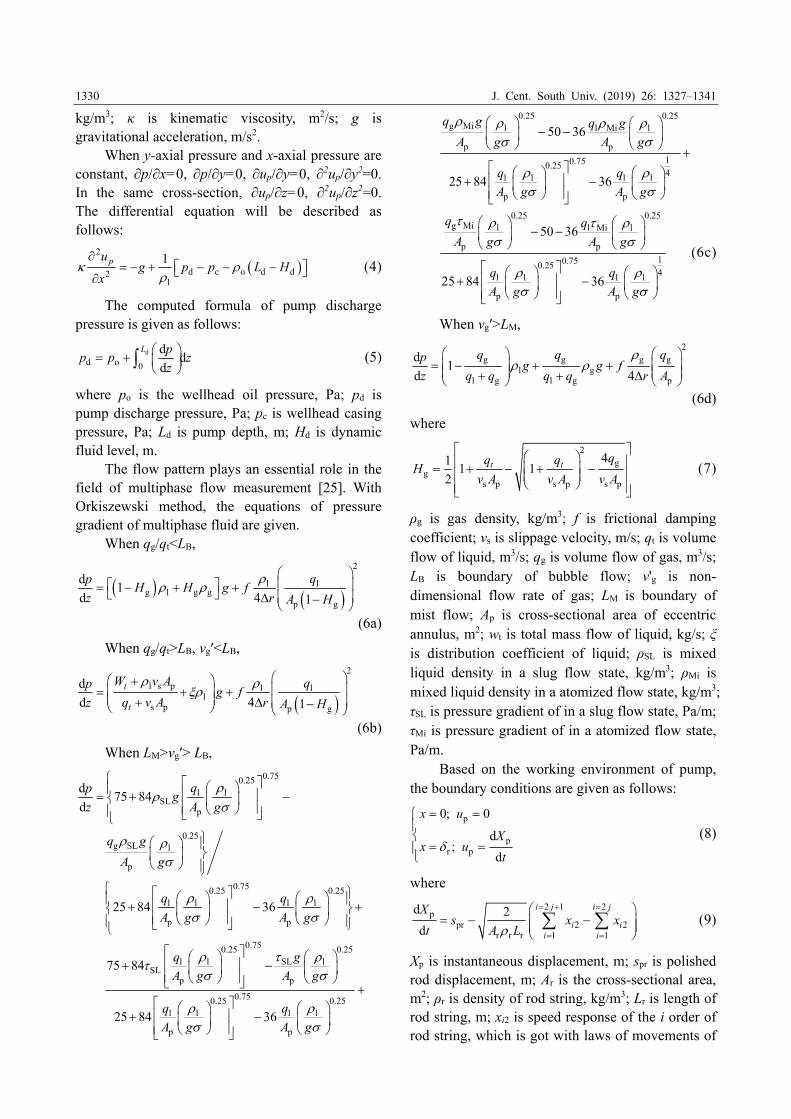
When the axis center of pump plunger is ensured concentric with the axis center of pump barrel, the length of pump plunger is 1 m, the stroke length is 3 m, the pump diameter is 0.056 m, the inner diameter of pump barrel is 0.066 m, the stroke number is 5 min–1, the density of crude oil is 890 kg/m3, the nonlinear power law index is 0.6 and the consistency index is 5 kgꞏsn–2/m. When the stroke length and number are changed separately, the liquid pressure curve between plunger and pump barrel is given in Figure 8. Figure 9 gives the change law of liquid pressure under influence of stroke number and consistency index. When other parameters remain the same, the pump plunger and clearance height are changed separately and the liquid pressure curve is given in Figure 10. When the power law index and consistency index are changed separately, Figure 11 gives the liquid pressure curve under influence of power law index and consistency index.
Based on the above figures, when the stroke number and length are increasing, the liquid

J. Cent. South Univ. (2019) 26: 1327–1341
1334
Figure 7 Simulion method with software ANSYS: (a) Entity model; (b) Preprocess of simulation model; (c) Simulation
results; (d) Calculation flow chart of annulus fluid
J. Cent. South Univ. (2019) 26: 1327–1341
1335
Figure 8 Influence of stroke length and number
Figure 9 Influence of stroke number and consistency
index
Figure 10 Influence of pump length and clearance height
pressure will be increased. The change rules of liquid pressure with stroke number and length are the same. The reason is that the plunger speed is changed when the stroke number or stroke length is changed.
Therefore, the liquid pressure is affected by relative speed between liquid and pump barrel. With the same parameters, the liquid pressure is affected by consistency index. The greater the consistency
Figure 11 Influence of power law index and consistency
index
index of power law fluid is, the more the liquid pressure will be. The liquid pressure is increasing with increasing plunger length. Under the same environmental condition, the liquid pressure of long-shaft pump is bigger than that of short shaft pump. At the same time, when the clearance height of pump is changed, the liquid pressure will be changed. Therefore, the liquid pressure is decreasing with increasing the clearance height. In addition, the liquid pressure is influenced by power law index and consistency index which are important physical parameters of non-Newtonian fluid.
For pseudo-plastic fluid, liquid pressure of pump is increasing with increasing the power law index and consistency index. Therefore, pump life and plunger load are affected by different production fluid flowing in polymer or water flooding wells. The influence of liquid property is necessary considered when the energy saving of sucker rod pumping system is studied.
When the eccentric distance is considered, the pump pressure is simulated. When other parameters remain the same, the eccentric distance is varied from 0.05 mm to 0.25 mm and the power law index is varied from 0.2 to 1.0, the change curves of liquid pressure are given in Figure 12.
With Figure 12, the liquid pressure is decreasing with increasing eccentric distance. When power law index is less than 1.0, the pressure curve with different eccentric distance has small amplitude range and the power law index is greater than or equal to 1.0, the pressure curve fluctuates greatly. The liquid pressure is increasing with

J. Cent. South Univ. (2019) 26: 1327–1341
1336
Figure 12 Change curve of liquid pressure and power law index
increasing power law index. Comparing with eccentric distance, the influence of power law index to liquid pressure is very large. Therefore, the liquid property is an important parameter for simulation and optimization of pump.
With the above-mentioned analysis, the liquid pressure of pump is affected by the liquid speed, pump structure and liquid property. The major impact factors are analyzed by orthogonal experimental method, such as consistency index, clearance height and stroke number. When the stroke length is 3 m, power law index is 0.6,
plunger length is 1 m, stroke number is varied from 2 to 8 min–1, consistency index is varied from 2 to 10 kgꞏsn–2/m, and clearance height is varied from 0.1 to 0.5 mm. Figure 13 gives the liquid pressure of pump distribution with consistency index and stroke number in 3D space. When the clearance height and stroke number or clearance height and consistency index are changed, the liquid pressure of pump distribution are given in Figures 14 and Figure 15.
From the above figures, when consistency index and stroke number are changed at the same

J. Cent. South Univ. (2019) 26: 1327–1341
1337
Figure 13 Liquid pressure distribution with consistency index and stroke number in 3D space: (a) Clearance height
δ=0.1 mm and δ=0.2 mm; (b) Clearance height δ=0.3 mm and δ=0.4 mm
Figure 14 Influence of stroke number–clearance height
Figure 15 Influence of clearance height–consistency
index
time, the liquid pressure continuously increases, which is irregular diamond distribution in 3D space. The liquid pressure will be larger, when the rod pump operates with high stroke number and small gap between plunger and pump barrel. Besides,
considering the joint influence of stroke number and clearance height and clearance height and consistency index and clearance height, the pressure distributing figures are given in 3D space, which will provide theoretic foundation for optimal design of pump in special wells such as heavy oil well or polymer flooding well. 4.3 Plunger friction
Based on the results of pressure simulation in wellbore and annular space, the plunger friction is computed with simulation model using optimized algorithm of Lagrange multiplier theorem. In general, the crank angle is defined as time function and the week of crank is a cycle period. When the stroke number is changed with sufficient liquid supply, the instantaneous fluid friction of pump plunger is computed and the curves of instantaneous friction and the maximum friction are given in Figure 16(a). Meanwhile, when the clearance grade of pump, pump diameter, moisture content and crude oil viscosity are changed separately, the curves of plunger friction are given in Figures 16(b)–(e).
With Figure 16, the instantaneous liquid friction of pump plunger is nonlinear; when the stroke number is increasing with sufficient liquid supply, the curve of liquid friction of pump plunger is moving to the direction of increase friction, and the maximum friction is increasing. The clearance grade is a key parameter affecting liquid friction of plunger. When the clearance grade is increasing, the liquid friction of plunger is decreasing rapidly. Meanwhile, the pump diameter, moisture content

J. Cent. South Univ. (2019) 26: 1327–1341
1338
and crude oil viscosity are analyzed. The results show that the liquid friction of plunger is increasing with increasing the pump diameter or crude oil viscosity, and the maximum friction is increasing. Comparing with pump diameter, stroke number, clearance grade and crude oil viscosity, the influence of moisture content on liquid friction of plunger is small. 4.4 Pump valve resistance
Based on the mathematical model of pump
valve resistance, the results of instantaneous valve resistance are got. When the stroke number, pump diameter and crude oil viscosity are changed, the simulation curves of pump valve resistance are given in Figure 17.
With Figure 17, when the stroke number is creasing, the pump valve resistance is increasing. The maximum resistance of pump valve is a parabola-like curve, which is consistent to the mathematical model. When pump diameter is increasing, the valve resistance will increase and
Figure 16 Instantaneous friction of plunger: (a) Influence of stroke number; (b) Influence of clearance grade; (c) Influence of pump diameter; (d) Influence of moisture content; (e) Influence of crude oil viscosity

J. Cent. South Univ. (2019) 26: 1327–1341
1339
Figure 17 Curve of pump valve resistance: (a) Influence
of stroke number; (b) Influence of pump diameter;
(c) Influence of crude oil viscosity
then decrease. When the crude oil viscosity is increasing, the valve resistance is increasing. 5 Conclusions
The flow characteristic of annular multiphase fluid in pump is studied, which can help to get performance parameters affecting pump efficiency. Therefore, considering the characteristic of geometrical nonlinear and rheology property of
multiphase fluid, an entire dynamics model of annular fluid flow is built. The entire mathematic model is composed of partial differential equation of annular fluid and differential equations of pressure gradient of multiphase fluid. Based on above models, considering hydraulic loss and friction loss, a simulation model of plunger friction and an improved model of hydraulic resistance of pump valve are built. Finally, a novel simulation method of fluid pressure in annular space is proposed with software ANSYS. The curves of experiment and simulation results are given. The simulation curve is found to be in good agreement with experimental curve.
The computational method of pressure gradient and characteristic are given. The results show that the pressure gradient of fluid is decreasing with increasing stroke number or pump diameter. The pressure gradient is increasing with increasing the moisture content or oil density. And the change law of discharge pressure is consistent with pressure gradient. In optimal design of pump motion parameters, the liquid pressure is increasing with increasing the stroke number or stroke length. In optimal design of pump structural, the influence of clearance height to liquid pressure is that of greater than plunger length. In optimal design of annular liquid, the power law index and consistency index are all important parameters, which is a significant impact on liquid pressure. Therefore, considering the motion parameters, pump structural and liquid property, the pressure distributing figures are given in 3D space.
The plunger friction and valve resistance are analyzed. The results show that the liquid friction curve of pump plunger and valve resistance curve are characteristic of nonlinearity. When the stroke number is increasing, the curve of liquid friction of plunger is moving to the direction of increase friction, and the maximum friction is increasing. The liquid friction is decreasing rapidly with increasing the clearance grade. The liquid friction is increasing with increasing the pump diameter or crude oil viscosity, and the maximum friction is increasing. Meanwhile, the pump valve resistance is increasing with increasing stroke number, pump diameter or crude oil viscosity. The simulation results provide theoretic foundation for optimal design of pump efficiency and SRPS in special well.

J. Cent. South Univ. (2019) 26: 1327–1341
1340
References [1] XING M M, DONG S M, TONG Z X, TIAN R F, CHEN
H L. Dynamic simulation and efficiency analysis of beam
pumping system [J]. Journal of Central South University,
2015, 22(9): 3367–3379. DOI: 10.1007/s11771-015-2877-z.
[2] LUAN G H, HE S L, YANG Z, ZHAO H Y, HU J H. A
Prediction model for a new deep-rod pumping system [J].
Journal of Petroleum Science & Engineering, 2011, 80(1):
75–80. DOI:10.1016/j.petrol.2011.10.011.
[3] XING M M, DONG S M. A new simulation model for a
beam-pumping system applied in energy saving and
resource-consumption reduction [J]. SPE Production &
Operations, 2015, 30(2): 130–140. DOI:10.2118/173190-PA.
[4] TAKACS G. Ways to obtain optimum power efficiency of
artificial lift installations [C]// SPE Oil and Gas India
Conference and Exhibition. Mumbai, India, 2010:
SPE-126544. DOI: 10.2118/126544-MS.
[5] CUI Z H, YU G A, AN J G. Sucker rod pumping equipment
and technology-sucker rod pumping system [M]. Beijing:
Petroleum Industry Press, 1994: 20–71. (in Chinese)
[6] MOREIRA A P, LEPIKSON H A, SCHNITMAN L,
RAMALHO G L, MATOS F. Characterization of the driving
unit of linear submerged double acting pumping system [C]//
SPE Artificial Lift Conference—Latin America and
Caribbean. Salvador, Bahia, Brazil, 2015: SPE-173922-MS.
DOI: 10.2118/173922-MS.
[7] ZHANG H, LI Y, WANG H, LI X, ZHANG Z, HUANG B,
HAN Q. Development of the forced pull rod type hollow gas
prevention pump for CO2 flooding [J]. China Petroleum
Machinery, 2017, 45(1): 95–97. DOI:10.16082/j.cnki.issn.
1001-4578.2017.01.020. (in Chinese)
[8] YANG Z, LIU W, LIU Y G, CHEN H Q, ZHANG P P.
Anti-leakage of hydraulic feedback heavy-oil pump [J].
Special Oil and Gas Reservoirs, 2016, 23(4): 147–150. DOI:
10.3969/j.issn.1006-6535.2016.04.035. (in Chinese)
[9] SHEN D C, ZHANG G T, AI W C. Sucker rod pumping
equipment and technology-pump [M]. Beijing: Petroleum
Industry Press, 1994: 123–205. (in Chinese)
[10] de AZEVEDO V W F, de LIMA J A, PALADINO E E. A 3D
transient model for the multiphase flow in a
progressing-cavity pump [J]. SPE Journal, 2016, 21(04):
1458–1469. DOI: 10.2118/178924-PA.
[11] ZHOU L, BAI L, LI W, SHI W D, WANG C. PIV validation
of different turbulence models used for numerical simulation
of a centrifugal pump diffuser [J]. Engineering Computations,
2018, 35(1): 2–17. DOI: 10.1108/EC-07-2016-0251.
[12] ORKISZEWSKI J. Predicting two-phase pressure drops in
vertical pipe [J]. JPT, 1967, 19(6): 829–838. DOI:
10.2118/1546-PA.
[13] BEGGS D H, BRILL J P. A study of two-phase flow in
inclined pipes [J]. JPT, 1973, 25(5): 607–617. DOI:
10.2118/4007-PA.
[14] HASAN A, KABIR C. A study of multiphase flow behavior
in vertical wells [J]. SPE Production Engineering, 1988, 3(2):
263–272. DOI: 10.2118/15138-PA.
[15] DONG S. Computer simulation of dynamic parameters of
rod pumping system optimization [M]. Beijing: Petroleum
Industry Press, 2003: 52–64. DOI: 103969/j.issn.1007-
791X.2011.04.003. (in Chinese)
[16] DONG S, XING M, ZHANG H, CHAI G. Study of
reasonable flowing pressure of rod pumping wells based on
maximum system efficiency [J]. Journal of Yanshan
University, 2011, 35(4): 296–308. (in Chinese)
[17] PALKA K, CZYZ J. Optimizing downhole fluid production
of sucker-rod pumps with variable motor speed [J]. SPE
Production & Operations, 2009, 24(2): 346–352. DOI:
10.2118/113186-PA.
[18] HAN H S, QU C L, WANG Q W, AN M F, LI H. The indoor
experiments on the oil-well pump effciency at different
inclined angles [J]. Science Technology & Engineering, 2010,
10(36): 9073–9076. DOI: 10.3969/j.issn.1671-1815.2010.
36.030. (in Chinese)
[19] WANG Y, WANG S, YANG L, PU H, LING K. A new model
to evaluate polished rod load of sucker rod pumping system
[C]// SPE Liquids-Rich Basins Conference - North America,
5–6, 2018, SPE-191803-MS. DOI: 10.2118/191803-MS.
[20] TANG Y, LIU Z, LIU P, KANG W. A novel ice slurry
producing system with vacuum freezing [J]. Journal of
Central South University, 2017, 24(3): 736–742. DOI:
10.1007/s11771-017-3475-z.
[21] BAKHTIZIN R N, URAZAKOV K R, LATYPOV B M,
ISHMUKHAMETOV B H, NARBUTOVSKIKH A. The
influence of regular microrelief forms on fluid leakage
through plunger pair of sucker rod pump (Russian) [J]. Oil
Industry Journal, 2017, 4: 113–116. DOI: 10.24887/0028-
2448-2017-4-113-116.
[22] HULSURKAR P, AWOLEKE O, AHMADI M.
Experimental study of the multiphase flow of sand, viscous
oil, and gas in a horizontal pipe [J]. SPE Production &
Operations, 2018, 33(4): 837–856. DOI: 10.2118/187212-
MS.
[23] WU B, WANG X L, LIU H, XU H L. Numerical simulation
and analysis of solid-liquid two-phase three-dimensional
unsteady flow in centrifugal slurry pump [J]. Journal of
Central South University, 2015, 22(8): 3008–3016. DOI:
10.1007/s11771-015-2837-7.
[24] TAN C, WANG N, DONG F. Oil-water two-phase flow
pattern analysis with ERT based measurement and
multivariate maximum Lyapunov exponent [J]. Journal of
Central South University, 2016, 23(1): 240–248. DOI:
10.1007/s11771-016-3067-3.
[25] HUANG S, SUN A, ZHOU T, ZHOU J. Application of
time–frequency entropy from wake oscillation to gas–liquid
flow pattern identification [J]. Journal of Central South
University, 2018, 25(7): 1690–1700. DOI: 10.1007/s11771-
018-3860-2.
(Edited by YANG Hua)

J. Cent. South Univ. (2019) 26: 1327–1341
1341
中文导读
抽油泵柱塞与泵筒环形空间内的多相流体特性 摘要:进行抽油泵性能参数分析是泵效和有杆抽油系统优化设计的基础。为此,本文考虑抽油泵结构
几何非线性和多相流体的流变特性,进行了抽油泵性能参数的仿真研究。首先,进行了环空流体动力
学分析,建立了描述环空流体流动规律的动力学模型和流体压力梯度的计算模型。其次,对柱塞摩擦
力和泵阀隙水力损失进行了分析,建立了柱塞摩擦力和泵阀隙水力损失的仿真模型。最后,基于有限
元分析软件,提出了环空流体压力的仿真方法。基于实验和仿真数据,进行了仿真模型精度的对比验
证。应用 VB 6.0 软件,编制了整体系统的数值仿真算法,并进行了动态参数仿真。仿真结果表明:
柱塞摩擦力和泵阀隙水力损失的变化规律具有显著的非线性特征。与此同时,进行了抽油泵性能参数
影响因素分析并给出了相应特性曲线。研究结果对抽油泵性能参数优化和抽油泵整体结构的合理设计
具有要的实际意义。 关键词:有杆抽油系统;抽油泵;柱塞;泵筒;性能参数