
Flowmeter for space - NASA · FLOWMETER FOR SPACE ... is the measurement of pressure drop across a...
28
NASA TECHNICAL NOTE NASA D2517 c. / LW OOPY : m!r!JRh *" m (WLOL) KIRTUWD AFB, N MEX FLOWMETER FOR SPACE by T. F. Mowis George C. Marshall Space Fligbt Center Huntsville, A la. *?.* NATIONAL AERONAUTICS AND SPACE ADMINISTRATION WASHINGTON, D. C. DECEMBER 1969 6 https://ntrs.nasa.gov/search.jsp?R=19700003089 2018-06-07T13:58:02+00:00Z
-
Upload
trinhthuan -
Category
Documents
-
view
217 -
download
2
Transcript of Flowmeter for space - NASA · FLOWMETER FOR SPACE ... is the measurement of pressure drop across a...

NASA TECHNICAL NOTE N A S A D 2 5 1 7 c. /
L W OOPY : m!r!JRh *"
m (WLOL) KIRTUWD AFB, N MEX
FLOWMETER FOR SPACE
by T. F. Mowis George C. Marshall Space Fligbt Center Huntsville, A la.
*?.*
N A T I O N A L A E R O N A U T I C S A N D SPACE A D M I N I S T R A T I O N W A S H I N G T O N , D. C. DECEMBER 1 9 6 9
6
https://ntrs.nasa.gov/search.jsp?R=19700003089 2018-06-07T13:58:02+00:00Z

TECH LIBRARY KAFB, NM
This report discusses the development of a mass flowmeter designed for use in outer space. from purges and collected leaks at leak ports, on aerospace hardware, dis- charging into a space environment. One of the most notable features of the flowmeter is the capability to measure the flow of all common gases such as hydrogen, helium, nitrogen, oxygen, and organic vapors. These gases can be measured over a wide range of flowrates (nitrogen, 5 sccm to 2500 sccm) in a space environment of zero-gravity with pressure ranging from 1.333 x IO- i to 1.33 x N/m2 (I x to I x torr) and with temperature extremes of 70- to 500" K.
The purpose of the flowmeter is to measure flowrate;
I111111 lllll lilll111111111111111 lllll Ill1 1111
21- NO. o f pages
27
2. Government Accession No. I 1. Report No. NASA TN D-5517
4. T i t l e and Subtit le
Flowmeter for Space
7. Author(s1 1 T. F. Morris
George C.. Marshall Space Flight Center Marshall Space Flight Center , Alabama 3581 2
9. Performing Orgor i ta t ion Name ond Address
22. P r i ce*
$3.00
12. Sponsoring Agency Nome and Address I
- . OL32LL9
TECHNICAL REPORT STANDARD T I T L E PAGE
3. Recipient's Cotalog No.
5. Report Date December 1969 5. Performing Organirotian Code
~~
3 . Performing Organization Report No. M651
D. Work Un i t No. 932-40-27-00-62
1. Controct or Gront No.
3. Type of Report and Per iod Covered
Technical Note
15. Supplementory Notes Prepared by the Quality and Reliability Assurance Laboratory, Science and Engineering Directorate
4. Sponsoring Agency Code
116. Abstract
17. K e y Words 18. Distr ibut ion Statement
Undassifiea - Unlimited
19. Security Clorsi f . (of th is report) 20. Security Clossif. (of th is poge)
~~
Unclassified I Unclassified i * F o r sa l e by the Clearinghouse fo r Fede ra l Scientific and Technical Information
Springfield, Virginia 22151

I -1l'-i -
TABLE OF CONTENTS
Page
SUMMARY ........................................ I
INTRODUCTION .................................... I
D E S C R I P T I O N . . . . . . . . . . . . . . . . . . . . . . . . . . . . . . . . . . . . . . 2
Desi gn........................................ 2 Test ......................................... 6 F i n a l D e s i g n . ................................... 10
CONCLUSIONS AND RECOMMENDATIONS. . . . . . . . . . . . . . . . . . . 13
APPEND ......................................... 14
L I S T OF FIGURES
Figure
I.
2.
A-I.
A-2.
A-3.
Title Page
Prototype f lowmeter . .................... 7
Final configuration of f lowmeter . . . . . . . . . . . . . I1
Nitrogen flow calibration. . . . . . . . . . . . . . . . . . 15
Helium da ta and theoretical curve. . . . . . . . . . . . 18
21 Effect of p r e s s u r e variation. . . . . . . . . . . . . . . .
iii

FLOWMETER FOR SPACE
SUMMARY
The task of developing a suitable flowmeter to support orbital inspection
The objective was approached in a three-phase effort; Phase I , and chtckout operations of large space stations and interplanetary vehicles was undertaken. prototype design; Phase 11, prototype fabrication and test; Phase 111, final design and documentation.
The design phase of this contract resulted in a preliminary prototype design utilizing an orifice-meter measuring system. This system con- sisted of the following three subsystems: ( i) gas handling and conditioning system , ( 2) orificing system , and ( 3) pressure measurement system.
A f t e r the preliminary design had been developed and approved, a proto- type flowmeter was built and tested, first by the contractor and then by Marshall Space Flight Center. The contractor's test program consisted of functional checkout , altitude ascent rate , and flow calibration. MSFC made further tests to ( I) verify calibration of flowmeter, ( 2) calibrate the instru- ment over the entire meter range, ( 3) determine the effects of external pressure variations, ( 4) verify operation with helium, and ( 5) determine the adequacy of temperature control system.
The technical design and operation of the prototype w a s so successful that final design was directed primarily toward human engineering factors and safety considerations. A documentation package was developed, including drawings , instructions , and specifications for a flight worthy mass flowmeter. Planning calls for procurement and testing of flight prototype hardware for performance evaluation and environmental qualification pending funding approval.
INTRODUCTION
Current planning for future space exploration indicates the need for a suitable flowmeter to support orbital inspection and checkout operations of large space stations and interplanetary vehicles prior to launch from parking orbits. Most existing flowmeters are either dependent upon earth gravity for

operation or a r e sensitive to the effects of gravity. Their operation is also designed around the earth environment and is greatly affected by the pressure at the meter outlet.
This program was undertaken to develop a mass flowmeter for measuring flow rates from purges and collected leaks at leak ports, on aerospace hard- ware, discharging into a space environment. The objective was to be accom- plished in a three-phase effort: Phase I, prototype design; Phase 11, prototype fabrication and test; and Phase 111, final design and documentation.
To ensure that the instrument would be suitable for use by an astronaut in space, several design and operational requirements were placed on the con- tractor. Most notable of these requirements was the ability to measure the flow of all common gases such as hydrogen, helium, nitrogen, oxygen, and organic vapors, at rates as low as 5 sccm and as high as 650 sccm in the space environment of zero-gravity with pressures ranging from I. 333 x IO-' to I. 333 x IO-" N/m2 (1 x of 7 0 ° b 500OK.
to I x torr) and with temperature extremes
DESCRIPTION
Des ig n
The design phase of this project resulted in a preliminary prototype design utilizing an orifice-meter measuring system. The basis of this system is the measurement of the pressure drop across a restriction in the gas stream. Because of the low ambient pressure of outer space, upstream pressure equals A P and the restriction can be selected so that it always operates in the super- critical regime. Thus, knowing the gas characteristics, temperature, and pressure, the flowrate is readily determined by
where a is the orifice radius, K is the flow coefficient, M is the molecular weight of gas, P is the upstream pressure, T is the gas temperature, and Q is the gas flow.
2

To make these measurements and determine the flowrate, the proto- type flowmeter was designed with three main subsystems: ( I) the gas handling and conditioning system, ( 2) the orificing system, and ( 3) the pressure measurement system.
Gas Handling and Conditioning .~ System. The gas handling and condition- ing system was designed to receive the flow from a leak o r purge port, conduct it through a temperature conditioning chamber to the orifice manifold, and exhaust it into space. The gas handling portion is rather straightforward, using standard AN fittings and tubing. The temperature conditioning, however, is rather unusual. Normally in flow measurement, a correction is applied to the indicated flow for variations in temperature , but, in this system, the temperature of the gas is maintained within certain limits and the flow is read directly. It is feasible to regulate the gas temperature in this particular application since the maximum flow measurable is a relatively small mass, and heat transfer to the space environment is only by radiation.
The radiation to space was controlled by building the flowmeter case a s a box within a box and utilizing "superinsulation" between the walls. This "superinsulation, developed for insulating cryogenic tanks on the Saturn pro- gram, consists of multiple layers of aluminized Kapton film and is effective as an insulator only when the ambient pressure is I. 333 x'10-I N/m2 ( torr) 0.r less. This design limited the heat loss from the package to approximately I. 4 watts when exposed to 20°K and the heat gain to 2.9 watts when exposed to 500°K.
The temperature of the gas entering the orifice manifold is regulated by passing the gas through a chamber attached to a large heat sink. mass of the gas is small and velocity through the chamber is low, the gas stabilizes at the temperature of the heat sink. elements powered from a rechargeable 9-volt battery and controlled by a 300°K ( 80" F ) thermostat. that is, by a canister of dodecahydrate of sodium biphosphate attached to the heat sink. This hydrated salt loses its water of crystallization between the temperatures of 306°K ( 92°F ) and 322°K ( 120°F) ,,.and, in the process of becoming a liquid, i t absorbs approximately 14 x I O 4 joules (39 watt-hours) of energy per 0.4536 kg ( I lb) . The process is fully reversible. When hot gas enters the flowmeter, the hydrated salt melts, absorbs heat from the gas, and effectively controls the temperature. Overall , the temperature of gas entering the orifice manifold is maintained between 297°K ( 75" F ) and 325°K (125O F) ; the heaters do not allow the temperature to drop below 297. K, and the hydrated salt keeps the temperature at 325.K or less.
Since the
The sink is heated by resistance
Cooling is accomplished by a rather unique method,
3

It might appear that this wide range over which the temperature can fluctuate would introduce a large e r ror in the flow measurement. However, this is not the case. In the mass flow equation, temperature appears as (T) With mass flow varying inversely with the square root of the absolute tempera- ture, a 305" K ( 90" F ) mean temperature with *30.5"K ( *55" F ) variation would produce a maximum flow e r ro r of only 5 percent. This i s an acceptable e r ro r in this application; however, it should be noted that this is a worst case and the actual e r ror for a particular reading would normally be much better.
Calculations revealed that heat loss caused by 650 sccm of nitrogen gas entering the instrument at 20°K is 3. 8 watts and the heat gain with a gas tem- perature of 500°K is 2. 5 watts. Combining the effects caused by gas tempera- ture and radiation to space, the total worst case heat loss is 5 . 2 watts and heat gain is 5 . 4 watts. joules (22 watt-hours) of energy available and the salt canister has approxi- mately 7 . 2 x IO4 joules (20 watt-hours) of energy, giving a minimum oper- ational life of approximately 5 hours at high gas flow at lowest ambient temper- ature and about 3 1/2 hours at high gas flow at highest ambient temperature.
The battery selected has approximately 7.9 x IO4
Orificing System. The orificing system is the heart of the operation of the flowmeter, and the principle of operation is one of basic simplicity. The gas flow to be measured is brought to the previously described tempera- ture range (297O to 325OK) and exhausted to space through an orifice. In this application the exhaust pressure ( space vacuum) is very low, ensuring that the flow orifices a re always operating in the supercritical regime. Thus the flow through the orifice is dependent only upon the upstream pressure, and, for a given gas, a given orifice, and a given pressure gage, the mass flow can be expressed with good accuracy by:
where Q is the mass flow, K is the calibration constant, and %P is the pressure gage reading in percentage of full scale.
The wide variety of gases to be measured and the wide range of flow- rates required that more than one orifice be used to obtain accurate readings with a single pressure gage and also hold measurement time within the speci- fied 90 seconds. Calculations using the critical orifice flow equation estab-
4

lished that three orifices would be adequate. A 0.0439-cm (0.0173-in. ) diameter orifice, the smallest, w a s chosen to measure the minimum hydrogen flow, and the intermediate orifice, with a 0.0782-cm (0.0308-in. ) diameter, w a s chosen to measure the minimum nitrogen flow as well as the high flow of hydrogen. The largest orifice, 0.2667-cm (0.105-in. ) diameter, was chosen to measure the upperYlow ranges of nitrogen and oxygen and a t the same time give adequate capacity for gases of higher molecular weight. orifice for a flow measurement is selected with a toggle valve.
The proper
The orifice holes were produced by the l'Elox'l electromachining process in 0. 005-cm (0. 002-in. ) and 0. 0127-cm ( 0. 005-in. found that piercing single plates resulted in burrs , but by sandwiching several plates together the interior plates would be free of burrs. Because of the fragile nature of the orifice plates, they are individually mounted between bezels and can be changed through the bottom of the enclosure by dismounting only the exhaust duct. valve that vents the orifice manifold directly to the space environment.
stainless steel. It was
The orifice plates are also protected by a system relief
Pressure _ _ - .~ Measurement . System. The last major subsystem of the
The main item of this system is a pressure flowmeter , the pressure measurement system , performs the actual flow sensing and displays the numerical value. gauge wi th a f u l l scale pressure of 20 inches of water . The particular gauge selected for the prototype is a fairly rugged gauge and can withstand 100 per- cent overpressure without change of calibration. It has been qualified for ground support equipment use , but further qualification will be necessary prior to use in a flight experiment.
A s explained previously, the orifices in this device operate in the super- critical regime , making mass flow through the orifices directly proportional to the upstream pressure. It is a straightforward procedure to calibrate the pressure meter for the various gases. with percent of full scale and calibration curves used to give actual flowrate, o r a multiple scale can be used with flowrate being read directly. Either approach has merit , and the final determination will be made through flight experiment development.
The meter scale can be either marked
The pressure gauge is protected from destructive overpressure by two devices, a system relief valve and a gauge overpressure cutoff valve. The system relief valve was mentioned earlier in conjunction with protection of the orifice plates. the gauge. The gauge overpressure cutoff valve, in series with the gauge, is diaphram operated and closes when line pressure exceeds a preset value of
Venting to protect the orifices also relieves pressure to
5

7 . 4 7 x IO3 N/m2 (30 inches of water. used regularly to protect gauges of this type from pressure surges.
This is a fast-acting device that is
A thermometer is also included in the pressure measurement system, but it is physically mounted on the orifice manifold. Here it measures the actual temperature of the gas, allowing the determination of a temperature correction factor for application to the measured flow if the ultimate accuracy of the system is required for a particular measurement. The thermometer also serves another useful purpose in that it indicates proper operation of the temperature control system. If the temperature drops below 297°K ( 75°F) , a malfunction in the electrical circuit is indicated while temperature in excess of 325OK ( 125°F) indicates the need for recharging the salt canister.
Test
After the preliminary design had been developed and approved, a pro- totype flowmeter (Fig. I) was built and tested. Testing w a s first conducted by the contractor and then the flowmeter was turned over to MSFC for further test, verification , and acceptance.
Contractor Test Program. The contractor test program consisted of ( I) functional checkout, ( 2) altitude ascent rate, and ( 3) flow calibration.
Functional checkout. The functional checkout was initiated with a leakage check using a helium mass spectrometer. The leakage was determined to be less than IO-* a h cc per second with all selector valves closed.
To test the functioning of the overpressure protection devices, the inlet was over pressured to 16 .19 x l o3 N/m2 ( 6 5 inches of water) , which is approx- imately five times the maximum design pressure and 50 times the design flow- rate of the flowmeter. The protective devices actuated properly and subsequent tests of the flowmeter showed no indications of damage.
The thermal control heating circuit was operated for approximately one week (from an external power source to conserve the battery) in a bell j a r at a pressure of approximately 26.66 N/m2 ( 200 microns). The thermal load was such that the typical thermostat cycle was 30 seconds on and 2 minutes off, resulting in an average power consumption of 1 . 4 watts. Temper- ature was maintained within 0.55OK ( lo F) with no indication of change of set point.
c
6

Figure I. Prototype flowmeter.
Altitude ascent rate. To simulate the reaction of the flowmeter to a take off pressure profile, the prototype flowmeter was placed in a bell jar and rapidly depressurized. The maximum depressurization rate obtainable with the pump used dropped the pressure from atmospheric to I. 333 x IO’ N/m’ ( I torr) in 32 seconds. This is much more severe than any actual takeoff profile. A t this high depressurization rate, the maximum pressure gauge deflection w a s approximately half scale with only the small orifice being open and the inlet fitting capped off. No disturbances were seen in the multilayer thermal insulation. Also, a test was conducted to determine the effects of
7

rapid repressurization that would occur when returning from a space vacuum into the spacecraft through an airlock. could be repressurized at a maximum $ate of 3 .45 x lo4 N/m2 ( 5 psi) per second without over pressurizing the gauge element.
This test showed that the flowmeter
Flow calibration. After the various subsystems were determined to be operating properly, the flowmeter was calibrated with nitrogen gas. The flowrate was measured by timing the displacement of a known volume of gas at constant temperature and pressure. The volume of gas was displaced from a calibrated glass cylinder by an oil piston. The flowmeter was placed in a glass bell jar pumped by a mechanical pump rated at 4 . 2 5 x IO-I m* (15 cfm) . This pump was able to maintain the following orifice pressure ratios over a major portion of the flow range of each orifice: orifice number 1, 7. 5; orifice number 2, 100; and orifice number 3, 350. In actual use the flowmeter would discharge into space, producing higher orifice pressure ratios. How- ever, the test ratios obtained were well above critical and the calibration e r ro r was quite small, more than acceptable for verification of the prototype operation.
MSFC Test Program. Upon completion of testing by the contractor, the prototype flowmeter was delivered to MSFC for further tests and accept- ance. The objectives of these tests were a s follows:
I. To verify the calibration of the flowmeter.
2. To calibrate the instrument over the entire meter range using nitrogen.
3. To determine the effects of variations of external pressure on the flowmeter.
4. To make verification tests using helium.
5. To determine the adequacy of the temperature control system.
The flowmeter was tested in a small vacuum chamber pumped by a 50. 8-cm (20-in. ) diffusion pump and a 14.5 m3 (500 cfm) mechanical pump. A vacuum range of 6 . 6 5 x IO-' N/m2 (5 x lo-* torr) was attainable for ful l flow through orifice number 2. For orifice number I, only the large mechani- cal pump was used and was capable of chamber pressures below 2 6 . 6 N/m2 (2 x lo-' torr) for the largest flowrates. Failure of the diffusion pump forced orifice number 3 to be tested using only the mechanical pump. the vacuum range for this orifice, about 3 .99 N/m2 (3 x lo-' torr) , was not a s high as desired.
Therefore,
e
F
8

Flowrate was measured by timing the displacement of a predetermined volume of gas at a known temperature and pressure. The displacement was accomplished using a VOL-U-METER.
For each orifice, the nitrogen calibration data were taken first, then pressure variation data were taken for pressures up to I. 333 x IO2 N/m2 ( I tor r ) , and finally, several data were taken using helium gas. A l l flow rates were converted to flows at an orifice temperature of 297.6"K (76" F). To make this conversion,
Q2 = ( s2) v 2
where Q is the flowrate and T is the absolute temperature of orifice.
The results of the nitrogen flow calibrations are shown in Figures A - i and A-2 in the Appendix. In all the curves, the abscissa is the observed reading of the pressure gauge. (corrected for an orifice temperature of 297.6OK) along with the contractor's calibration curves. for the two smaller orifices. For the large flow orifice, the data for the two curves deviated, but this discrepancy was caused by the higher capacity vacuum capabilities at MSFC. A l l data obtained were repeatable and consistent within 2 percent of a linear function.
Figure A-1 shows the actual data points
The agreement of the two calibration curves was excellent
The data obtained using a helium leak source were also consistently linear and repeatable, behaving in a similar manner to the nitrogen data. A theoretical prediction of the helium data was made from the nitrogen data using the molecular weights and specific heats of the two gases a s follows:
QHe
QN2 =( MN? MHe )"' / k
He
k ~ ~
where M is the molecular weight, k 'is the ratio of specific heats; and Q is the mass flow.
9

Figure A-2 shows the helium data and the theoretical curve obtained from the nitrogen data. The helium data varied about 10 percent from pre- dictions, showing that a calibration for each gas to be measured will probably be necessary.
The flowmeter was tested in a vacuum range of 1 .333 x l o 2 N/m2 torr) to determine the effects of (1 torr) to 1. 333 x l o m 2 N/m2 (1 x
external pressure. Figure A-3 shows the flow coefficient (at a constant flow- rate) plotted against external pressure. coefficient introduced at these extremes was 6 percent. However, most of the deviation occurs above 1. 333 x lo - ' N/m2 ( 1 X torr) , making this problem negligible in a high vacuum environment.
The maximum deviation of the flow
Testing the temperature control system with the flowmeter in the vacuum chamber became an insurmountable problem and had to be abandoned. The mass flowrate and velocity of the gas through the meter was so low that heat transfer between the gas, the interconnecting equipment, and the atmos- phere brought the gas to ambient temperature prior to entering the tempera- ture conditioning section of the flowmeter. Gas could not be supplied to the flowmeter with sufficient temperature (high or low) to activate the regulating circuits. A test was made at ambient conditions by bleeding vapor from an LN, Dewar directly into the flowmeter. This actuated the heater circuit as the temperature dropped below 297°K ( 75" F) . Although the heater could not handle this unreasonably high cryogenic flow, the regulating circuit oper- ated properly.
Final Design
Since little effort was made in the initial design and test phase to pro- duce a prototype that approached flight configuration, a final design and doc- umentation effort was conducted to develop a complete documentation package for a flyable mass flowmeter. The original technical design and the operation of the protolype proved so successful that this final effort was directed pri- marily toward human engineering factors and safety considerations. of this effort was the removal of all sharp edges or projections that could be detrimental to the astronaut or his protective clothing, enlargement of the carrying handles to be compatible with the space suit gloves, and modification of the toggle valve lever for visibility and foolproof operation. One minor design deficiency w a s discovered and corrected. A spirit type thermometer was originally specified to measure gas temperature; however, in the zero- gravity of space, these do not function accurately; that i s , the fluid separates
Typical
10
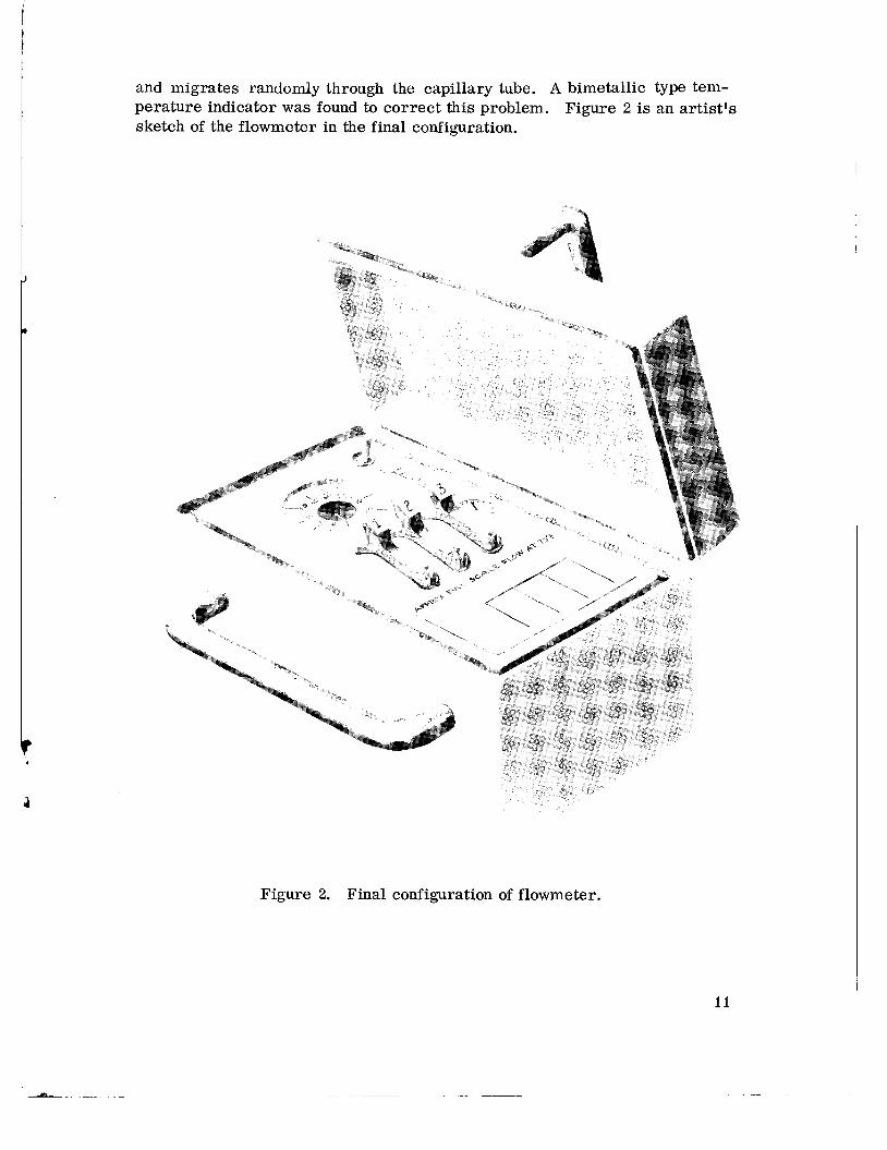
and migrates randomly through the capillary tube. A bimetallic type tem- perature indicator was found to correct this problem. sketch of the flowmeter in the final configuration.
Figure 2 is an artist's
. 9
Figure 2. Final configuration of flowmeter.

The documentation package contains complete drawings instructions and specifications to allow competitive procurement of the mass flowmeter.
The following table summarizes the operating characteristics of the flowmeter.
Approximate over all weight
Overall package size including handles and inlet fitting (L x W x H)
Ambient temperature range
Maximum operating back pressure to insure thermal insulation
Maximum operating back pressure to insure flow metering accuracy
Approximate ful l scale flow at 297" K (75" F) [sccm at 293°K (68OF),10.13 x IO4 N/m2 ('760 to r r ) ]
3.51 kilograms (7-3/4 pounds)
0.317 x 0.235 x 0.216 meter (12-1/2 x 9-1/4 x 8-1/2 inches)
20°K to 500°K
1.333 x lo-' N/m2 torr)
1.333 N/m2 torr)
Orifice 1
Hydrogen
Helium
Nitrogen
Oxygen
9500
7000
2500
2400
2 3
850
650
2 50
225
270
200
75
70
c ? !T
P
12

Orifice pressure at fu l l scale flow
Battery specifications:
Type
Number of cells
Voltage of full charge
Approximate full charge energy recoverable
Heat Sink Specifications:
Temperature range of crystallization phase change
Inlet Connection:
49.8 x 10’ N/m2 (20 in. HzO)
Storage, Sealed Silver Zinc
6
Approximately 9 volts
7 . 9 ~ lo4 joules (22 watt-hours)
Utilizes latent heat of crystallization of NaH PO4 12H20, rechargeable
306°K to 322OK (92°F to 12O0F)
0.635 cm (1/4 inch) female flare (AN)
CONCLUS IONS A N D RECOMMENDATIONS
The developm,ent of a mass flowmeter designed specifically for use in outer space has proved to be highly successful. A thorough concept study and preliminary design resulted in a prototype flowmeter whose performance was well within contract limitations and exceeded operational requirements. A firm basis exists for building flight hardware for use in space.
The next step to be taken is the procurement and testing of flight pro- totype hardware for performance evaluation and environmental qual if ic ation. Plans are being made to initiate this effort in fiscal year 70. With successful accomplishment of this follow-on, the final effort will be a flight experiment or engineering demonstration.
George C. Marshall Space Flight Center National Aeronautics and Space Administration
Marshall Space Flight Center, Alabama 35812, August 25, 1969
13

APPENDIX
NITROGEN FLOW CALIBRATION, HELIUM DATA, AND EFFECT OF PRESSURE VARIATION
The following graphs were not plotted according to SI units, and the conversion would distort their meaning; therefore, the original units have been retained.
14


20 13
PRESSURE (INCHES OF HzO)
Figure A-I. ( Continued).

PRESSURE (INCHES OF HZO)
Figure A-I. ( Concluded).
13 20

Figure A-2. Helium data and theoretical curve.
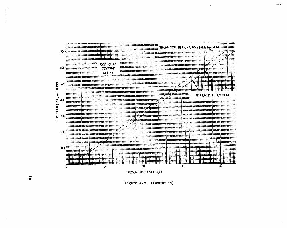
Figure A-2. ( Continued).

tw 0
- K K 0 t- O W h
U' 0 N
a I U U m v
z 0 J L
20 PRESSURE ( IN~HES OF HZO)
Figure A-2. (Concluded),

W
VACUUM (TORR)
Figure A-3. Effect of pressure variation.

.204
.202
VACUUM (TORR)
Figure A-3. ( Continued) ,

I
E
VACUUM (TORR)
N w Figure A-3. ( Concluded).

NATIONAL AERONAUTICS AND SPACE ADMINISTRATION WASHINGTON, D. C. 20546
OFFICIAL BUSINESS FIRST CLASS MAIL
POSTAGE AND FEES PAID NATIONAL AERONAUTICS AND
SPACE ADMINISTRATION
POSTMASTER: If Undeliverable (Section 15s 1 , Postal Manual) Do Nor Return
-- f I
I “The aesonnittical mad spuce activities of the United States shall be conducted so as t o contribute . . . t o the expansion of himan knoiol- edge of phenonieiza i f z t he a~iiiosphese a d space. The Adniinis t~at ioa
“shall psovide fos the widest practicable rind aFpropriate dissemiizntio~z of iiafotxintion concerziag its actirities and the resitlts thereof.” .. ~-
-NATI~NAL AERONAUTICS AND SPACE ACT OF 1958
NASA‘ SCIQNTIFIC AND TECHNICAL PUBLICATIONS
TECHNICAL REPORTS: Scientific and technical information considered important, complete, and a listing contribution to existing knowledge.
TECHN1,CAL NOTES: Information less broad in scope but nevertheless of importance as a contribution to existing knowledge.
TECHNICAL MEMORANDUMS : Information receiving limited distribution because of preliminary data, security classifica- tion, or other reasons.
TECHNICAL TRANSLATIONS: Information published in a foreign language considered to merit NASA distribution in English.
SPECIAL PUBLICATIONS: Information derived from or of value to NASA activities. Publications include conference proceedings, monographs, data compilations, handbooks, sourcebooks, and special bibliographies.
TECHNOLOGY UTILIZATION PUBLICATIONS: Information on technology used by NASA that may be of particular interest in commercial and other non-aerospace applications. Publications include Tech Briefs, Ttchnology Utilizarion Reports and N ~ ~ ~ ~ , and Technology Surveys.
CONTRACTOR REPORTS: Scientific and technical information generated under a NASA contract or grant and considered an important contribution to existing knowledge.
Details on the availability of these publications may be obtained from:
SCIENTIFIC A N D TECHNICAL INFORMATION DIVISION NATIONAL AERO N AUTlCS AND SPACE ADM I N ISTRATI 0 N
Washington, D.C. 20546


![User's AXF Manual Magnetic Flowmeter Integral Flowmeter ... · Magnetic Flowmeter Integral Flowmeter/ Remote Flowtube [Hardware Edition] IM 01E20D01-01E IM 01E20D01-01E 7th Edition.](https://static.fdocuments.in/doc/165x107/5e9c29fa54300501b21ae83a/users-axf-manual-magnetic-flowmeter-integral-flowmeter-magnetic-flowmeter-integral.jpg)
![User's AXF Manual Magnetic Flowmeter Integral Flowmeter ... · User's Manual Yo kogawa Electric Corporation AXF Magnetic Flowmeter Integral Flowmeter/ Remote Flowtube [Hardware Edition]](https://static.fdocuments.in/doc/165x107/5c40f15893f3c338c3289cbb/users-axf-manual-magnetic-flowmeter-integral-flowmeter-users-manual-yo.jpg)


![User´s AXFA14G/C Manual Magnetic Flowmeter Remote ... · AXFA14G/C Magnetic Flowmeter Remote Converter [Hardware Edition/Software Edition] AXF Magnetic Flowmeter Integral Flowmeter](https://static.fdocuments.in/doc/165x107/5e9c29ae5a06915e2b2224e0/users-axfa14gc-manual-magnetic-flowmeter-remote-axfa14gc-magnetic-flowmeter.jpg)