Crawler Crane LR 1130 EN - bms.dkMenuItemByDocId...Crawler Crane LR 1130 LR 1002.03 EN
Upload
gipszjakabCategory
view
221download
0
7/27/2019 Flowfront 2008may Lr
http://slidepdf.com/reader/full/flowfront-2008may-lr 1/40
MAY 2008
Accessibility
Congurability
Process Integration
Communication Focus
StrategicImplementation
Enterprise-Enabled
Simulation
www.owfront.comMF-FF05-1008
492 Old Connecticut Path Suite 401 Framingham, MA 01701 USA
SPECIAL
CONFERENCEISSUE .

7/27/2019 Flowfront 2008may Lr
http://slidepdf.com/reader/full/flowfront-2008may-lr 2/40
LenovoThinkStation
Best-engineeredworkstationChange the way you work with a smarter workstation,
ThinkStation from Lenovo gives professionals the performance
they need to do more, faster, ThinkStation is Lenovo’s bestengineering at work, featuring Intel® Xeon® processor technology.

7/27/2019 Flowfront 2008may Lr
http://slidepdf.com/reader/full/flowfront-2008may-lr 3/40
I N T R O D U C I N G
Altair®
HyperWorks®
9.0
Built on a foundation of design optimization,
performance data management and process
automation, HyperWorks empowers
innovation and rapid decision-making to
get to the ‘right’ answer faster.
Pay-for-use CAE software licensing
Broadest ISV partner eco-system
Unequaled modeling, visualization and reporting
Next-generation solvers for linear, nonlinear
and multi-body dynamics applications
Recognized optimization technology leader
Computing environment virtualization tools
Automated performance data management
For more information visit:www.altairhyperworks.com/HW90
Call for Presentations and formore information visit www.altairhtc.com
India HTC Aug. 07 - 09
Americas HTC Sept. 16 - 17
European HTCSept. 30 - Oct. 1
Korea HTCOct. 17
China HTCOct. 23 - 24
Japan HTCNov. 13 - 14
Altair HyperWorks is a division of
2008 HyperWorks TechnologyConference Global Series
A Platform for InnovationTM
i i

7/27/2019 Flowfront 2008may Lr
http://slidepdf.com/reader/full/flowfront-2008may-lr 4/40
www.ansys.com
ANSYS, Inc. I Southpointe I 275 Technology Drive I Canonsburg, PA 15317 I USA I 724.746.3304 I 1.866.267.9724
Does your engineering simulationsolution meet your virtualprototyping needs?
Simulation Driven Product DevelopmentTM processes enabled by ANSYS, Inc. can reduce development
time and prototype testing, provide faster time to market and accelerate the market acceptance of innovative new products. Built on a flexible foundation that is engineered
for scalability with highly adaptive architecture, engineering simulation
technology from ANSYS provides comprehensive multiphysics
solutions that can innovate and transform product
development — from the desktop across the enterprise.
Join the world’s most innovative organizations — 96 of the
FORTUNE 100 leading industrial companies — who knowthe cost of being wrong and use engineering simulation
solutions from ANSYS.
©
2 0 0 8 A N S Y S ,
I n c .
A l l R i g h t s R e s e r v e d .
Solve it with ANSYS.
For more than 35 years, companies have relied upon ANSYS for
technology, and to deliver innovative winning products to market
better, faster and cheaper.

7/27/2019 Flowfront 2008may Lr
http://slidepdf.com/reader/full/flowfront-2008may-lr 5/40
Copyright © 2008 Moldow Corporation. All rights reserved. Flowfront is a publication of Moldow Corporation. Moldow, Moldow Plastics Advisers, MPA,Moldow Plastics Insight, MPI, Moldlfow Plastics Insight Enterprise Edition and MPI-e are trademarks or registered trademarks of Moldow Corporationand/or its subsidiaries worldwide. All other trademarks are properties of their respective holders.
contents
focus
columns
COVER STORY 18 Enterprise-Enabled Simulation
FROM THE EDITOR 7 Enterprise-Enabled Simulation
WHAT’S NEW Latest Releases of Moldow Design AnalysisSoftware Support Enterprise-enabled Vision 9 Moldow Plastics Insight 6.2 11 Moldow Plalstics Advisers 8.1
TIPS & TECHNIQUES 28 Tips to Facilitate Report Generation 31 Automating the Creation of Results
Files Using the Moldow Plastics Insight API
REAL WORLD SUCCESS 14 Industry Spotlight: Automotive Customers
Implement Simulation to Address CriticalIssues
25 3D Gas-Assisted Injection Molding SimulationStreamlines Concept-to-Production
PERSPECTIVE
35 Taking Concurrent Engineering One StepFurther: Consider Recycling
departments
9
18
11
7/27/2019 Flowfront 2008may Lr
http://slidepdf.com/reader/full/flowfront-2008may-lr 6/40
Learn more at: www.moldflow.com/change
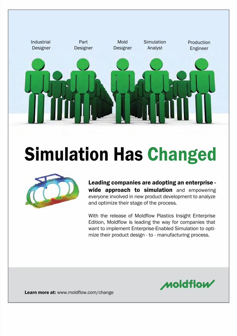
Leading companies are adopting an enterprise -
wide approach to simulation and empowering
everyone involved in new product development to analyze
and optimize their stage of the process.
With the release of Moldflow Plastics Insight Enterprise
Edition, Moldflow is leading the way for companies that
want to implement Enterprise-Enabled Simulation to opti-
mize their product design - to - manufacturing process.
Industrial
Designer
Part
Designer
Simulation
Analyst
Production
Engineer
Mold
Designer
Simulation Has Changed
7/27/2019 Flowfront 2008may Lr
http://slidepdf.com/reader/full/flowfront-2008may-lr 7/40
www.owfront.com 7Flowfront | May 2008
This issue of Flowfront focuses on a new paradigm for implementingplastics simulation technology in today’s global enterprises.Enterprise-enabled simulation is about expanding the use of
simulation technology beyond a single stage of product development.Moldflow is changing the way simulation technology is utilized to allowusers at any stage of product development, from industrial design toprocess engineering, to access the technology, configure it to bestmeet their specific needs, easily integrate it into their work processes,communicate results among the entire design-to-production team, andtake advantage of strategic, enterprise-wide implementation.
Enterprise-enabled simulation is about breaking traditional barriers tobring the benets of simulation to a wider population, who will analyze
a broader range of designs and perform those analyses not only totroubleshoot problems, but also to validate and, ideally, to optimize plasticspart and mold designs at the earliest stages of product development.Read more about Moldow’s vision of enterprise-enabled simulation inour cover story, beginning on page 18.
In this issue, we also present highlights of our most recent releasesof Moldow Plastics Insight® (MPI®) and Moldow Plastics Advisers® (MPA®) products. New features and enhancements introduced in MPI 6.2and MPA 8.1 not only answer many user requests for improved usabilityand specic technology developments, but also support the enterprise-enabled simulation paradigm.
We examine some customer successes in the context of innovativemolding technologies and automotive industry-specic applications. Findout how Mack Molding Company (Arlington, VT) uses 3D simulation on agas-assisted injection molding design to optimize part and tool design,material selection and choice of molding process to assure productmanufacturability and durability. Read our automotive industry spotlightto see how companies including Jaguar and Promold are using Moldowsimulation to improve product quality, address environmental concerns,and stay competitive in a rapidly evolving industry.
You will also nd useful tips and techniques to help you communicateanalysis results more effectively. Learn how to create a script to automateexport of MPI results for viewing in Moldow Communicator, and takeadvantage of three specic tips to help you streamline report generationusing both MPI and MPA software.
Dr. Robert Malloy, Professor and Chairman of the Plastics EngineeringDepartment at the University of Massachusetts Lowell, offers his
perspective on designing for recycling. Dr. Malloy is a well-respectedresearcher and consultant in the areas of plastics processing, design,and recycling of thermoplastics and the author of many publications andpatents, including a textbook on plastic part design.
Throughout this issue, you’ll also see featured advertisements fromour iMUG 2008 sponsors. This year’s International Moldow User Groupconference takes place on May 20-22 in Detroit, MI.
Whatever role you ll in taking plastic parts from concept tomanufacturing, you will nd information here about Moldow technologyinnovations, real-world applications, and business practices to help youoptimize your product development process.
from the editor
Enterprise-Enabled
Simulation
published by
Moldow Corporation492 Old Connecticut Path, Suite 401
Framingham, MA 01701 USA
: +1 508.358.5848x: +1 508.358.5868b: www.owfront.com
mail: [email protected] Editor Ken Welch
tor Marcia Swanntributing Writers Murali AnnareddyMatthew JaworskiHanno van Raalte
Brian Satheraphic Design Liz Goncalvesculation Assistant Kristin Pepeblisher Peter Rucinskirketing Associate Melissa Aytek
ldow Corporation Executive ManagementRoland Thomas President & CEOKen Welch COOGreg Magoon EVP Finance/CFOLori Henderson CAO & General Counselan Pendlebury EVP Product Development
Peter Kennedy EVP/CTO
advertising information
: +1 508.358.5848 x258mail: [email protected]
case studies & press releases
: +1 508.358.5848 x289mail: [email protected]
for more information
bscribe, view online editions, download ad-rtising information and contact us at
www.owfront.com
dow Corporation publishes print and online edi-
ns of Flowfront magazine. Our print circulation
ches approximately 20,000 contacts worldwide who
e an interest in the entire plastics design-through-
nufacturing process, including product designers,
d designers, CAD users, mold and tool makers, CAE
lysts, process engineers, manufacturing profession-
and licensed users of Moldow products. For infor-
tion about the company and our products, services,
global ofce locations, visit:
www.moldow.com
M ar c i a S w an ,E d i t or

7/27/2019 Flowfront 2008may Lr
http://slidepdf.com/reader/full/flowfront-2008may-lr 8/40
Flowfront | May 20088 www.owfront.com
Complete 64-bit solution:
In MPI 6.2 and MPA 8.1, both thegraphical user interface (GUI)and the analysis solvers nativelysupport 64-bit operating systems(in previous releases, the GUI wasa 32-bit application running on
a 64-bit operating system). Thisenables more efcient handling oflarge models and improves overallproduct performance on Windowsx64-based platforms.
Microsoft Windows Vista ® support: Support for WindowsVista Business, Enterprise andUltimate Editions is added in MPI6.2 and MPA 8.1.
Microsoft Ofce ® 2007support: Project reports
generated in Word and PowerPoint
formats are compatible withMicrosoft Ofce 2007 Edition.
Congurable workspace
options: Task-specic userinterface congurations canbe saved and shared among
various stakeholders across theenterprise.
Product consistency
enhancements: MPI 6.2 and MPA8.1 introduce terminology changeswhich have been implemented toimprove consistency within eachproduct and across all Moldowproducts. Within each product,these changes reduce differencesbetween online Help topics andwhat is displayed in the userinterface, and also unify terms
used to refer to similar features
of the Dual Domain™ and 3Danalysis technologies. AcrossMoldow products, these changesreduce product-specic differencesin terms referring to similaranalysis technologies, analysissequences and results.
Moldow Communicator
compatibility: MPI 6.2 andMPA 8.1 Revision 3 supportexport of Moldow Results(*.mfr) les that can be viewedin Moldow Communicator 2.0.Moldow Communicator is afree utility developed specicallyfor visualizing, quantifying andcomparing Moldow Results les.
Details of product-specic changes are
described on the following pages.
what's new
Latest Releases
of Moldow Design Analysis Software Support Enterprise-Enabled Vision
B Y HANNO VAN RAALTE, PRODUCT LINE MANAGER, AND MURALI ANNAREDDY , DIRECTOR OF PRODUCT MARKETING
CAD ConnectivityTools
Structural CAE
InterfacesAPI
MPI & MPA Reports
MoldflowCommunicator
Training Services
Technical Support
Plastics Labs
MPA
MPI
MPI-e
Enterprise-Enabled Simulation
Changes common to both MPI 6.2 and MPA 8.1 include these:
The latest releases of Moldow Plastics Insight® (MPI®) and Moldow Plastics Advisers®
(MPA®) products support the company’s vision of enterprise-enabled simulation to optimizeplastic product development processes.

7/27/2019 Flowfront 2008may Lr
http://slidepdf.com/reader/full/flowfront-2008may-lr 9/40
www.owfront.com 9Flowfront | May 2008
Moldow Plastics Insight (MPI)6.2 introduces signicant userinterface enhancements andseveral new solver technologies torespond to customer requests andincrease user productivity.
User InterfaceEnhancements
Synergy Graphical UserInterface Updated
The Synergy GUI has undergonea signicant facelift in the MPI6.2 release, with newly designedicons and a new background,terminology changes, and newcommands. These changes followsimilar changes implemented inMPA to enhance compatibility
across product lines.In particular, new icons used
to indicate analysis status elimi-nate English language-dependentsymbols used previously, makingproduct localization more straight-forward and enhancing usability inthe global community.
Terminology changes havebeen implemented to createmore consistency between theMPI GUI and Help system andamong all Moldow products. The
most notable changes are made
to analysis sequence names (forinstance, Fill+Pack replaces Flowin the list of available analysissequences for most moldingprocesses), result names, andanalysis technology (Dual Domaintechnology is referenced instead of
using the Fusion product name).New commands include a Close
All Documents command availablefrom the Window menu, as wellas a new results Scaling toolbaravailable from the View menu,which allows dynamic adjustmentof the minimum and maximumscale of the displayed result.
Congurable WorkspaceOptions
MPI 6.2 introduces aWorkspacetool, a key feature aimed atimproving user productivity as wellas reducing product complexity tobroaden the use of MPI throughoutthe entire enterprise.
On a typical project, a majorityof the user’s time is spent ininteracting with the user interface.A customized user interface thatconforms to an optimal workowfor specic tasks has great potentialto improve user productivity. MPI,
with its ever-increasing productbreadth, can pose daunting training
and usability challenges, especiallyto novice users.
People in different roles in theproduct development processall would use MPI differently.For example, an industrialdesigner might want to perform
a manufacturing feasibility study,a plastics engineer might wantto evaluate material selectionoptions, a structural engineermight be interested in analysisresults such as weld line locations,ber orientation and predicteddisplacement, while a moldermight focus on machine selectionand process setup parameters. TheWorkspace tool allows the userinterface to be customized to ta user’s job function, knowledge,
skill set and experience.The following aspects of MPI
can be customized and saved to aworkspace le:
Molding processes
Analysis sequences
Mesh types
Databases (Thermoplastic/
Thermoset materials, Coolants,Mold materials, and Moldingmachines)
Analysis results
Menu toolbars
what's new
MoldowPlastics Insight 6.2

7/27/2019 Flowfront 2008may Lr
http://slidepdf.com/reader/full/flowfront-2008may-lr 10/40
Flowfront | May 200810 www.owfront.com
Meshing options
Several precongured work-
space les are distributed with MPI6.2 (identied as Moldow work-spaces). Besides these, you canset up personal (User) or shared(Company) workspaces.
New Interfaces withDevelopment Partners
Export to Altair ➠ ® Engineering’sH3D Data Format
MPI 6.2 offers the capabilityto export the meshed model andresults to Altair Engineering's H3Ddata format. Through this option,the MPI model and results canbe visualized in Altair HyperView9.0 and other Altair products thatsupport the H3D format.
Interface to Code V ➠ ® OpticalDesign Software
MPI 6.2 features an interfaceto CODE V, optical design softwarefrom Optical Research Associates®.Through this interface, it is possible
to export the optical propertiespredicted by a Birefringenceanalysis and use this informationto investigate how the moldingprocess affects the opticalproperties of lenses.
MPI Enterprise Edition
Enhancement Offers
Increased AccessibilityFor users of the MPI Enterprise
Edition (MPI-e), new in MPI 6.2 isthe ability to install the Moldow
Plastics Advisers (MPA) software
and access its suite of productsusing MPI-e tasks.
MPI-e users can leverage thisincreased accessibility to MPA andMPI products to allow more usersthroughout the enterprise to real-ize the benets of injection mold-ing simulation. In particular, partand mold designers as well as nov-ice simulation users now can takeadvantage of MPA’s guided user in-terface, model-specic design ad-vice, and wizard-driven runner andcooling channel modeling tools.
Solver TechnologyEnhancements
3D Flow Solver SpeedImprovements
The Coupled 3D Flow solveroffers a new AMG matrix solveroption, and the code has undergonerigorous review and optimizationto perform more efciently. Theaverage 3D Fill+Pack analysissequence using the Coupled 3DFlow solver now runs in less thanhalf the time required to perform thesame analysis in MPI 6.1, withoutaffecting the analysis results.
New AMG Matrix Solver Option➠
for Coupled 3D Flow Solver
An optional AMG solution methodis available for 3D Fill+Pack analysissequences using the Coupled 3DFlow solver. When this option isenabled, the average expectedanalysis time speed-up factor is 2.0or more (where the speed-up factor
is dened as the ratio of analysistime in MPI 6.1 to the analysis time
in MPI 6.2). The speed-up factor ismodel-dependent.
By default, the AMG matrixsolver selection option is setto Automatic. This setting allowsthe 3D Flow solver to examine themodel and determine whether ornot the AMG matrix solution is ad-vantageous. Various parameters in-uence the outcome of this setting,including the model size (numberof elements in the mesh), the op-erating system, and the selectedanalysis sequence and analysis pa-rameters.
The AMG matrix solver does notprovide a clear advantage for smallmodels (fewer than 200,000 tetra-hedral elements). The AMG matrixsolver also uses more memory (upto 50% more). As a result of thesetwo factors, on a 32-bit operatingsystem, the AMG matrix solver willnot be used when the solver selec-tion option is set to Automatic.
Coupled 3D Flow Solver➠
Optimization
An additional average speed-
up of 30% is achieved throughcode optimization and algorithmicimprovements. The speedimprovement depends uponseveral factors; key among theseare the model size, selectedmolding process, selected analysissequence (Fill or Fill+Pack), andthe hardware conguration.
New Advanced Gate Locator
MPI 6.2 introduces a new
Advanced Gate Locator algorithm for
what's new
1. Moldow Mold Designer Workspace 2. Moldow Optical Workspace

7/27/2019 Flowfront 2008may Lr
http://slidepdf.com/reader/full/flowfront-2008may-lr 11/40
www.owfront.com 11Flowfront | May 2008
Midplane, Dual Domain, and 3Dmeshes, which can help withmaking important gating decisions.The Advanced Gate Locator offerssignicant improvement over theprevious gate location algorithmwith two new capabilities:
Simultaneously search for
and recommend up to 10 gatelocations.
Account for specic regions
of the part geometry that havebeen prohibited from gatingconsiderations.
The Advanced Gate Locatoraims to identify gate locations thatwill produce the lowest injectionpressure. Regions that shouldnot be used for gating becauseof aesthetic, tooling or otherreasons, can be excluded before
starting the analysis by selectingspecic nodes on the model thatare designated as prohibited gatenodes. The Advanced Gate Locatorwill not consider prohibited nodesin searching for recommended gatelocations.
A Gate Location analysissequence in MPI 6.2 uses the newAdvanced Gate Locator algorithmby default. The previous gatelocation analysis algorithm hasbeen renamed to Gate Region
Locator.
Expanded Scope of 3D WarpAnalysis
3D Warp Analysis Handles More➠
Overmolding Congurations
Complex overmolded parts mayhave numerous congurations inwhich the various components arepositioned. Previously, only a limitedsubset of these congurations couldbe properly simulated for warpage
continued on page 12
MPA 8.1 delivers new
technologies and key enhancementsto help users analyze a broaderrange of parts with Advanced 3Dtechnology, improve productivitywith a redesigned user interface,shorten analysis preparationtime with powerful and exiblemodeling tools, interpret resultsmore efciently using new resultsvisualization options, and increasecollaboration with expandedcommunication capabilities.
Extended Solutionwith Advanced 3D
TechnologyAdvanced 3D analysis
technology provides the abilityto analyze accurately part (moldcavity) designs that have thickregions or abrupt changes inthickness. Geometry features suchas these are not suitable for MPA'sStandard Dual Domain analysistechnology, which has been
developed and ne-tuned for thethin-walled part geometry that is
most often encountered in plastic
injection molding applications.The Advanced 3D analysis optiondramatically increases the numberof designs that can be successfullyanalyzed using MPA software.TheAdvanced 3D analysis also workswith the Performance Adviser andCooling Circuit Adviser add-onmodules to evaluate part warpageand account for the effects of thecooling system, respectively.
continued on page 13
what's new
The new Advanced Gate Location analysis
can simultaneously search for up to 10 gatelocations and allows specied areas of the
part to be prohibited from the analysis.
MoldowPlastics Advisers 8.1
Advanced 3D analysis option handlesdesigns that have thick regions or abruptchanges in thickness.

7/27/2019 Flowfront 2008may Lr
http://slidepdf.com/reader/full/flowfront-2008may-lr 12/40
Flowfront | May 200812 www.owfront.com
using 3D meshes. An improvedalgorithm in 3D Warp nowestablishes contacts between allcomponents in single-shot and
2-shot overmolding applications,including part inserts.
The improved algorithm also isbetter able to tolerate small gapsbetween the meshes on differentovermolding components. Thisis particularly important whenworking with components that havecurved contact surfaces betweenthem, where it can be challengingto ensure perfect contact betweenthe meshes.
3D Warp Analysis for Gas-➠
assisted Injection Molding Applications
Product designers can nowevaluate the effect of hollowed-outgas channels on the overall partdeection. The 3D Warp analysiscan be run in parallel on a multi-processor system. The Isolatecause of warpage option is alsoavailable, which can help to identifythe source of warpage.
Exclude 3D Cold Runner➠
Elements from AnalysisMPI 6.2 now offers the ability to
assign a new Cold runner (3D)element property to tetrahedralelements. This allows the 3D Warpsolver to identify which elementsbelong to the part and which tothe cold runner system and toexclude the cold runners from thewarpage analysis. This improvesthe accuracy of the part warpagepredictions and reduces the analysistime. The new element property
does not change the Coupled 3DFlow or Cool solvers.
Other Enhancements
New Micro-mechanics Model➠
A new micro-mechanics model,the Mori-Tanaka model, has beenimplemented to provide moreaccurate shrinkage and warpagepredictions of ber-lled liquidcrystalline polymer (LCP) materials.The Mori-Tanaka micro mechanics
model is much better able tocapture the anisotropic nature ofLCPs, and this signicantly improvesthe calculation of mechanical
properties for this special class ofmaterials, which are often used inthe connector industry.
The Mori-Tanaka model can beused with Midplane, Dual Domainand 3D analysis technologies. Themodel is used automatically if theselected material contains theappropriate material propertiesdata.
Simulate Rapid Heating and➠
Cooling Processes
In the conventional injectionmolding process, the mold ismaintained at a near-constanttemperature throughout themolding cycle. However, newermolding techniques have beendeveloped which use a variablemold temperature. The mold ismaintained at a hotter temperatureduring the lling phase to facilitatelling and achieve smooth surfaceappearance. During the packingand cooling phases, the moldis switched to a much coolertemperature to assist in freezingthe part and decrease the cycletime.
MPI 6.2 allows variable moldsurface temperature proles tobe set up for use in Fill and Packanalyses. Variable temperatureproles can be specied onall element types (cavity, coldrunners, cold sprue, cold gatesand part beam) except hot runnerelements.
Venting Analysis for 3D➠
Reactive Molding and MicrochipEncapsulation Processes
Because the injectionpressures are often very low inreactive injection and microchipencapsulation molding processes,the build-up of air pressure in theunlled cavity due to inadequateventing can inuence the materialow during lling.
MPI 6.2 offers the capability tospecify venting analysis locations
and vent sizes, which are thenconsidered in the ow analysiswhen the option to perform ventinganalysis is enabled. The venting
analysis calculates the air pressurebuild-up in the unlled cavity, basedon the venting locations and sizes,and accounts for the inuenceof the air pressure on the llingpattern. This feature is supportedfor 3D Reactive Molding and 3DMicrochip Encapsulation moldingprocesses only.
User-specied Gate Size for 3D➠
Meshes
The new Gate contact diam-eter setting allows the gate sizeto be specied at a single injectionpoint on 3D meshes that do nothave a runner system and gate(s)explicitly modeled.
New Annular Beam Element➠
Formulation
A new formulation to representannular hot runners explicitlyimproves analysis accuracy usingMidplane and Dual Domain analysistechnologies.
Pack and Warp Analysis of➠
Thermoset Materials Extended to All Mesh Types
In MPI 6.2, it is now possibleto simulate the packing, shrinkageand warpage characteristics ofthermoset materials for ReactiveMolding and Microchip Encapsulationprocesses using Midplane and DualDomain analysis technologies. ■
Moldow Plastics insight 6.2│ continued
what's new

7/27/2019 Flowfront 2008may Lr
http://slidepdf.com/reader/full/flowfront-2008may-lr 13/40
www.owfront.com 13Flowfront | May 2008
what's new
Focus on Productivity
and Ease-of-useMPA 8.1 features a panel-
based user interface that has beendesigned to streamline projectmanagement tasks, improveaccess to analysis results andsupplemental information, andenhance user productivity, whilemaintaining the familiar, guidedworkow established in previousMPA releases.
Congurable WorkspaceOptions
Show or hide panels and toolbarsto customize the workspaceconguration for a specicworkow. For example, createone workspace to support tasksprior to running an analysis anda second workspace for reviewingand comparing results.
Save the customized workspaceto a le for later reuse or sharing
with other MPA users across theenterprise.
MPA provides two pre-conguredworkspaces and remembers thelast-used workspace congurationwhen you reopen the software.You can easily switch from oneworkspace conguration to anotherat any time.
Powerful and Flexible
Modeling ToolsRunner and cooling channel
layouts can be quickly and easilyimported from CAD systems orcreated using new modeling planes,snap tools, and visual cues to aid inprecise positioning.
New Runner System Wizard produces a complete feedsystem automatically based onuser-specied sprue, runner andgate properties.
Modeling planes feature aids
in quick and easy creation ofrunner and cooling channelsegments.
Visual cues are offered when
modeling runner segments toassist in their creation.
Export optimized runner and
cooling channel layouts for reusein a CAD system.
Intuitive ResultsInterpretation
New results visualization optionsallow for the comparison of resultsfrom multiple analysis iterations torealize design improvements andbetter understand plastics materialbehavior. New Dynamic Help functionality allows users to quicklyunderstand those results that havethe greatest impact on optimizingtheir part and mold designs.
Increased
CollaborationEnhanced report generation
capabilities make it possible toautomatically generate reports inMicrosoft® Word® or PowerPoint®
formats in addition to web-readyHTML format, to easily communicatevaluable analysis results across theenterprise.
Smart ToolsMPA 8.1 features a redesigned
Cost Adviser that facilitates
detailed part cost analysis.Association with the model allowsevaluation of how changes to partdesign, mold design, materialchoice, and processing conditionsaffect part cost. After the CostAdviser is set up for a givenproject, it will track the changes tothe model, material and processingconditions automatically anddisplay the current cost based onmaterial usage, cycle times, post-molding costs, operating costs and
overheads. ■For more information about MPA 8.1and MPI 6.2, contact your local Moldowrepresentative or visit www.moldow.com.
The panel-based user in-
terface design streamlinesworkow, provides unin-terrupted access to themodel, and improves over -all user productivity.
Easily create project reports in Micro-
soft Word or PowerPoint formats.
Moldow Plastics Advisers 8.1│ continued

7/27/2019 Flowfront 2008may Lr
http://slidepdf.com/reader/full/flowfront-2008may-lr 14/40
14 Flowfront | May 2008 www.owfront.com
From a consumer standpoint there has beena denite shift in purchasing considerationsover the last two years. Concerns about safety
and serviceability have gone down while interestin environmental friendliness and alternative fuelsources has risen signicantly.
Now, more than ever, major automakers andtheir suppliers are harnessing Moldow simulation toimprove their product quality, make their products
more environmentally friendly, and stay competitivein their market.
Product QualityFor over 75 years Jaguar, based in Coventry,
England, has manufactured vehicles that deliver aunique blend of style, luxury, and performance. As apremium car maker, they consider product quality tobe paramount. According to a review in New London,Connecticut’s The Day newspaper, "Jaguar´s qualityis ranked above that of its European rivals, Mercedes-Benz, BMW and Audi.” With world-class engineeringtalent and advanced design and optimization tools,
Jaguar continues its rich and distinguished heritageof innovative automotive manufacturing.
One challenge Jaguar has had to surmount is dueto the increasing number of plastic parts being used ininterior, exterior, and under-hood applications. Untilrecently, the company had been leaving analysis oftheir plastic parts to their suppliers and had not beenperforming up-front work in-house to optimize theirdesigns for manufacturability. This often resulted inlate design changes, costly rework, and the risk ofentire programs being late for crucial milestones.
On a center console nisher for their new Jaguar
XF interior, they identied multiple problems in theparts coming from the original mold design. Air traps,poor ber orientation, sink marks, and unacceptablewarpage resulted in a 42% scrap rate at an estimatedcost of $1 million in scrap and rework.
In an effort to address these issues as early aspossible in the product development cycle, Jaguarinvested in Moldow Plastics Insight® (MPI®) softwareto test three different changes to the thickness inthe center of the part where lling hesitation wasoccurring. On the third iteration, they found theoptimum wall thickness that produced a uniformlling pattern, appropriate ber orientation, and
minimal volumetric shrinkage. This design iteration
real world success
Even with all the current instability in theautomotive industry, executives are stillreporting the major issues they face havenot changed much in the past few years.According to KPMG’s 2008 Global AutoExecutive Survey, product quality, costreductions, harnessing new technolo-
gies, and global competition are the ma-
jor challenges, with environmental issuesbecoming more notable.
IndustrySpotlight: Automotive CustomersImplement Simulation
to Address Critical
Issues B Y BRIAN SATHER, TECHNICAL MARKETING SPECIALIST

7/27/2019 Flowfront 2008may Lr
http://slidepdf.com/reader/full/flowfront-2008may-lr 15/40
15www.owfront.com Flowfront | May 2008
real world success
also removed the weld lines entirely and pushed theair traps to the edge of the component.
Once the proper wall thickness was found forthe part design itself, the engineers used MPI tooptimize the processing parameters and cooling
system to minimize the amount of warpage thatoccurred in the molded part. After several iterations,the displacement in a critical area was reduced from12.8 mm to 1.2 mm. In production, this resulted in a13% decrease in the scrap rate due to warpage.
After the optimization, the total scrap rate wasreduced from 42% to 7%, with most of the remainingscrap due to the veneer in-mold decoration. Thecost savings on this project alone due to the reducedamount of scrap and improved production efciencyis estimated at over $1.1 million.
In total, 181 new plastic component designswere validated and optimized for the new Jaguar XFsport sedan using MPI software. With the successfulimplementation of MPI, Jaguar is now able to fullycontrol the part and mold and ensure the designsof each are fully optimized. Their dependency onsuppliers to get it right has been minimized alongwith the number of late design changes, the amount
Plastics Engineering GroupIncrease Simulation Efficiency
PEG GmbH Robert-Bosch-Str. 7 D-64293 Darmstadt Germany
Tel.: +49 6151 8725281 Fax: +49 6151 8725284 Cell: +49 170 3242921
[email protected] www.pe-group.de
flexible capacities
short deadlines
day to day service
MOLDFLOW users since 1989
proven record: > 4800 projects
MOLDFLOW experience > 75 years
access to all MOLDFLOW applications
individual reporting
multifaceted CAD data import
fixed rates ...
Meet us at iMUG conference,Detroit 2008
... and feel our experience!Contact us ...
Full analysis service- MOLDFLOW MPI, Midplane, Fusion, 3D- ABAQUS, ANSYS ...
Meshing services- high quality midplane modeling- ANSA, HYPERMESH, NX, CATIA
In total, 181 new plastic componentdesigns were validated and optimized forthe new Jaguar XF sport sedan using MPI
software.

7/27/2019 Flowfront 2008may Lr
http://slidepdf.com/reader/full/flowfront-2008may-lr 16/40
16 Flowfront | May 2008 www.owfront.com
of rework, and the risk of programs missing their setmilestones.
Environmental FriendlinessOver the past twenty years, automakers have
made evolutionary gains in fuel efciency fromimprovements and innovations in powertrain design.However, these improvements have been counteredby increases in vehicle weight because of the use ofhigher strength steels and other heavy safety featuressuch as airbags. For example, a 2008 Chevrolet Cobaltwith signicant improvements in engine efciencystill gets the same mileage as a similar 1988 model,because the Cobalt weighs 17% more.
To address environmental concerns, many auto-motive component manufacturers now are focusing
on nding ways to reduce carbon dioxide emissions byoptimizing their plastic part designs to reduce masswhile still maintaining product performance and qual-ity. This strategy not only helps improve fuel economyof the vehicles in which their parts are installed, butit also reduces the consumption of raw materials, the
energy needed for manufacturing, and the need forreplacement parts.
Promold, an engineering consultancy rm based
in Paris, France, offers MPI analysis services to theircustomers. Promold was contracted by Valeo, amajor supplier of automotive components to well-known vehicle manufacturers, to optimize the designof a new headlamp housing for a Renault sedan. Theinitial design weighed 244 grams with a wall thicknessof 2.15 mm. The constraints for manufacturing werethat the parts must be produced on an 800-metric-tonmolding machine and there could be no weld lines inthe vicinity of where the primary headlamp bulb wouldbe installed.
Promold used MPI software to virtually experimentwith three material options (polycarbonate, nylon,
and PBT), ve different part thicknesses rangingfrom 2.15mm to 0.8mm, and six different gatingcongurations. The experiment was set up to use thefull capacity of the designated molding machine’s 174MPa maximum injection pressure so the wall thicknesscould be reduced as much as possible. The rst stepwas to evaluate the three materials based on their
real world success
Industry Spotlight │ Automotive Customers
real power
To learn more about SolidWorks, visit our booth in the iMUG ’08 Exhibit Hall.
SolidWorks is a registered trademark and SWIFT is a trademark of SolidWorks Corporation. ©2007 Dassault Systèmes. All rights reserved.
IF YOU’RE NO SANDCASTLE SCULPTOR,USE SOLIDWORKS.
You don’t need to be a sculptor tocreate impressive designs in 3D. Thepowerful direct editing capabilities ofSolidWorks® (SWIFT™) simplify andautomate the design process for yourteam. So you can create compellingproducts that separate you from yourcompetitors.
DESIGN BETTER PRODUCTS
Skip Barber Racing School LLC usesSolidWorks 3D CAD
software to improveracecar performance,
while cutting designtime by approximately
80 percent.
i i

7/27/2019 Flowfront 2008may Lr
http://slidepdf.com/reader/full/flowfront-2008may-lr 17/40
17www.owfront.com Flowfront | May 2008
real world success
Product development is now commodity, must introduce product optimization andeal time ‘analytical vision’, if not, yourpetitors will...”
ow characteristics to minimize the pressure requiredto ll the part. Next, the wall thickness and numberof gates were optimized simultaneously to ensure theparts did not exceed the injection pressure limit ofthe machine and no weld lines were created in critical
areas.The experiment resulted in the selection of the
PBT material for a design with a wall thickness of only1.2 mm that used a 5-gate hot-runner system. Thenal weight of the part was 41% less than the originaldesign and took advantage of the full capability ofthe molding machine used. Performance and qualitycriteria were also met, with no weld lines in any criticalareas of the part and no sacrices in strength due tothe thinner walls.
Obviously, saving 100 grams in the weight of aheadlamp housing is not going to have a signicanteffect by itself on the fuel economy of a vehicle.
However, with plastics approaching 10% of the averagetotal vehicle weight, incorporating these methodsinto the best practices of an organization will ensurethat all new products developed will be optimized formass, and taken together, they can have a sizableimpact on a vehicle’s fuel efciency. Also, less materialconsumed and reduced amounts of energy requiredduring production present opportunities for costsavings in conjunction with improved environmentalfriendliness.
Going ForwardExecutives and directors in all major automotive
companies have recognized the importance of usingsimulation to stimulate innovation and to get productsto market as fast as possible. Those that haveimplemented Moldow injection molding simulation
software have seen great success in improving productquality and increasing environmental friendliness oftheir plastic products, as the examples described herehave shown.
Carlos Ghosn, CEO of Renault and Nissan, is largelycredited with the complete turnaround of Nissan since2005. Ghosn outlines a strategy of, “…using less andless prototypes, more digital simulation to decreasetime-to-market,” in his company’s 2009 StrategicPlan.
“Product development is now commodity, youmust introduce product optimization and a real time ‘analytical vision’, if not, your competitors will,” notes
John L. Sullivan, Ford’s Director of Process, Methods,Tools, and Information at a recent CAE conference.
Going forward, companies in the automotiveindustry, in particular, can benet from using simulationthroughout development to optimize every plasticproduct they produce. The greatest potential benetscome from moving beyond using simulation just todiscover and avoid potential problems and insteadusing simulation to truly optimization designs toaddress criteria that have been identied as mission-
critical to their businesses.Moldow’s vision of enterprise-enabled simulation
(see cover story on page 18) supports the immediateneeds of the automotive industry by providing amethodology that enables everyone involved in newproduct development, from industrial designers toprocess engineers, the ability to perform analysesand improve the design early and often. This type ofimplementation allows for the designs to be tailoredto whatever the best practices of the organizationdictate, whether it be product quality, environmentalfriendliness, time-to-market, or any trend currentlyshaping the industry. ■

7/27/2019 Flowfront 2008may Lr
http://slidepdf.com/reader/full/flowfront-2008may-lr 18/40
18 Flowfront | May 2008 www.owfront.com
cover story
Enterprise-enabled simulation is
a methodology for implementinganalysis software into the bestpractices of any organization thatdesigns and develops new products.
At its core, enterprise-enabled simulation isfocused on empowering
everyone involved in new productdevelopment to condentlyanalyze their own designs anduse the results to optimize partsfor both manufacturability andperformance.
Organizations involved inthe design and manufacture ofplastic parts are facing continuouspressure to get innovative productsto market faster than ever. Thesecompressed development cyclesoften result in simulation only beingused to troubleshoot or validatepart and mold designs in the latterstages of development. Failure toperform simulation early not onlyresults in a greater likelihood ofdefective parts, but also in lostopportunities to optimize theproduct for both manufacturabilityand performance.
The question now being posedby these organizations is, “How dowe incorporate simulation into ourbest practices so designs can beoptimized using analysis results?”
A Brief History of
Simulation UseThousands of companies around
the world currently employ simu-lation to some extent, and manyview it as a competitive differentia-tor. Over the course of three de-cades, the manner in which thesebusinesses use simulation hasevolved as the accuracy and speedof the software improved and asthey looked for new ways to out-pace their competitors.
Using Simulation as aTroubleshooting Tool
When simulation tools rstgained widespread use, it wastypically to x a problem discoveredin production environments or evenin end-use applications. A singleanalyst would then troubleshoot theproblem and determine a solutiongiven the existing constraints. Ofcourse, even if the analyst wassuccessful, valuable time andmaterial had already been wasted,driving up costs.
Enterprise-Enabled Simulation
B Y BRIAN SATHER, TECHNICAL MARKETING SPECIALIST

7/27/2019 Flowfront 2008may Lr
http://slidepdf.com/reader/full/flowfront-2008may-lr 19/40
19www.owfront.com Flowfront | May 2008
cover story
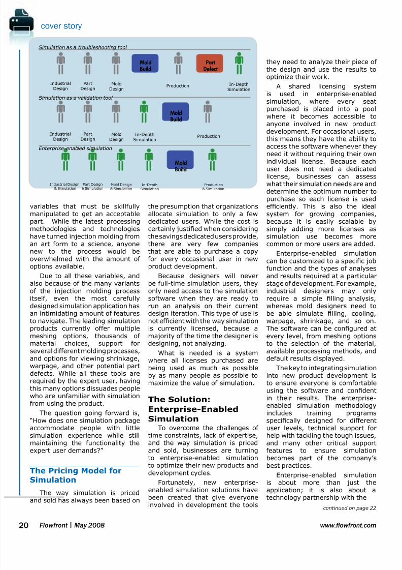
Using Simulation as aValidation Tool
As simulation tools andcomputers grew faster, the next
logical step was to validate part ormold designs prior to committingto the mold build. Any errors in thedesigns could be communicatedby the simulation expert to theengineer responsible, and the issuecould be xed prior to steel everbeing cut.
While this results in morevalue being realized from the useof simulation, there is still thepotential for signicant hiddencosts because parts and molds are
not being optimized. For example,without optimization, companiesare not determining if a part couldbe made thinner, which wouldreduce material usage, decreasecycle times, use less energy, andlower overall costs.
The problem with usingsimulation to troubleshoot existingproblems or validate designs is thatboth of these approaches focuson problem-xing and problem-avoidance, rather than on trying to
create truly optimized designs.
Current Trends in
SimulationGlobal competition, concerns
about the environmental impact ofnew products, and shortened timeto market are the critical pressuresthat businesses designing andmanufacturing plastic partsare currently facing. From anengineering standpoint, thesepressures translate into the need
to optimize product designs soeach part is manufactured at thelowest cost, with the least amountof material, and in the shortestdevelopment cycle possible.
Simulation Driven Design
Industry leaders are respondingto these pressures by implement-ing simulation earlier in the devel-opment stages to actually drivethe design of the part. Using thismethod, designs are analyzed and
improved iteratively so potentialproblems are solved preemptivelyand products are optimized prior tostarting production. This methodhas proven to be extremely effec-
tive because quality is now de-signed into the product and lesstesting is required in the laterstages, which improves the overallefciency of new product develop-ment.
Paul Hornikx, MechanicalEngineer in Microsoft’s hardwaredivision, speaks of the problemswith not utilizing simulation early: “Being late, and not knowing aboutit until the end, is very costly.Airship, losing shelf space, ying
engineers all over the place, lostengineering time for the nextprograms, and the stress on theengineering group is phenomenal.”He adds, “This should all beincentive to do analysis as early aspossible.”
Hornikx utilizes simulationearly in product development,performing analyses on industrialdesign concepts prior to addingthe internal engineering features.Recently, during the design of a
bottom case for a new keyboard,he found that a thick sectionaround the perimeter of the partwould have created a tension ringthat would cause the part to warpsignicantly.
Using the simulation results,Hornikx went back to industrialdesign with two options: move theparting line or reduce the thicknessof the sidewalls. He was able tonegotiate a 1.5 mm reductionin the thickness, which instantly
removed a majority of the warpagefrom the part.
Challenges in
Achieving Widespread
Simulation UseAn inherent problem with
plastics product development is thatpeople involved in the early stagesof design have the most inuenceon manufacturability, but it is theproduction engineers at the end ofdevelopment who are responsiblefor optimizing the process. Pushing
simulation into the earlier stagesof design counters this effect butpresents its own challenges due totime constraints, lack of expertise,and also because of the current
way simulation software is pricedand sold.
No Time for Simulation
Without question, runningmultiple analyses at each phasein the design of a new productwill increase the quality andmanufacturability of the part. Theproblem is that each analysis cantake anywhere from a few minutesto several hours to complete,due to model preparation, actualprocessing time, and results
interpretation. With alreadycompressed development cycles,the amount of time available to runthese analyses is very limited.
The challenge is to makesimulation as lean as possible foreach type of user, thus reducingthe amount of “waste” in the formof superuous results and extendedanalysis times.
Simulation: “Experts
Only” PleaseTypically, the use of injection
molding simulation is isolated toonly a few engineers within anorganization whose primary jobfunction is running analyses for therest of the development group. Thishas been the case for two reasons:the intricacy of the injection moldingprocess and the complexity of thesimulation application.
Crafting a successful injectionmolding process requires a thorough
understanding of the multitude of
PartDesign
MoldDesign
ProductionIndustrialDesign
MoldBuild
Responsibility
Influence
7/27/2019 Flowfront 2008may Lr
http://slidepdf.com/reader/full/flowfront-2008may-lr 20/40
cover story
20 Flowfront | May 2008 www.owfront.com
variables that must be skillfullymanipulated to get an acceptablepart. While the latest processingmethodologies and technologieshave turned injection molding froman art form to a science, anyonenew to the process would beoverwhelmed with the amount ofoptions available.
Due to all these variables, andalso because of the many variantsof the injection molding process
itself, even the most carefullydesigned simulation application hasan intimidating amount of featuresto navigate. The leading simulationproducts currently offer multiplemeshing options, thousands ofmaterial choices, support forseveral different molding processes,and options for viewing shrinkage,warpage, and other potential partdefects. While all these tools arerequired by the expert user, havingthis many options dissuades peoplewho are unfamiliar with simulationfrom using the product.
The question going forward is, “How does one simulation packageaccommodate people with littlesimulation experience while stillmaintaining the functionality theexpert user demands?”
The Pricing Model forSimulation
The way simulation is priced
and sold has always been based on
the presumption that organizationsallocate simulation to only a fewdedicated users. While the cost iscertainly justied when consideringthe savings dedicated users provide,there are very few companiesthat are able to purchase a copyfor every occasional user in newproduct development.
Because designers will neverbe full-time simulation users, theyonly need access to the simulation
software when they are ready torun an analysis on their currentdesign iteration. This type of use isnot efcient with the way simulationis currently licensed, because amajority of the time the designer isdesigning, not analyzing.
What is needed is a systemwhere all licenses purchased arebeing used as much as possibleby as many people as possible tomaximize the value of simulation.
The Solution:Enterprise-Enabled
SimulationTo overcome the challenges of
time constraints, lack of expertise,and the way simulation is pricedand sold, businesses are turningto enterprise-enabled simulationto optimize their new products anddevelopment cycles.
Fortunately, new enterprise-enabled simulation solutions have
been created that give everyoneinvolved in development the tools
they need to analyze their piece ofthe design and use the results tooptimize their work.
A shared licensing systemis used in enterprise-enabled
simulation, where every seatpurchased is placed into a poolwhere it becomes accessible toanyone involved in new productdevelopment. For occasional users,this means they have the ability toaccess the software whenever theyneed it without requiring their ownindividual license. Because eachuser does not need a dedicatedlicense, businesses can assesswhat their simulation needs are anddetermine the optimum number to
purchase so each license is usedefciently. This is also the idealsystem for growing companies,because it is easily scalable bysimply adding more licenses assimulation use becomes morecommon or more users are added.
Enterprise-enabled simulationcan be customized to a specic jobfunction and the types of analysesand results required at a particularstage of development. For example,industrial designers may only
require a simple lling analysis,whereas mold designers need tobe able simulate lling, cooling,warpage, shrinkage, and so on.The software can be congured atevery level, from meshing optionsto the selection of the material,available processing methods, anddefault results displayed.
The key to integrating simulationinto new product development isto ensure everyone is comfortableusing the software and condent
in their results. The enterprise-enabled simulation methodologyincludes training programsspecically designed for differentuser levels, technical support forhelp with tackling the tough issues,and many other critical supportfeatures to ensure simulationbecomes part of the company’sbest practices.
Enterprise-enabled simulationis about more than just theapplication; it is also about a
technology partnership with the
PartDesign
MoldDesign
ProductionIndustrialDesign
In-DepthSimulation
Part
Defect
Mold
Build
Simulation as a troubleshooting tool
Simulation as a validation tool
Enterprise-enabled simulation
PartDesign
MoldDesign
In-DepthSimulation
ProductionIndustrialDesign
Mold
Build
Part Design& Simulation
Mold Design& Simulation
Industrial Design& Simulation
In-DepthSimulation
Production& Simulation
Mold
Build
continued on page 22
7/27/2019 Flowfront 2008may Lr
http://slidepdf.com/reader/full/flowfront-2008may-lr 21/40
21www.owfront.com Flowfront | May 2008
cover story
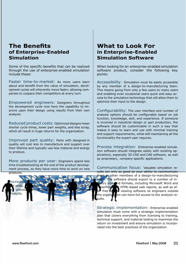
The Benets of Enterprise-Enabled
Simulation
Some of the specic benets that can be realizedthrough the use of enterprise-enabled simulationinclude these:
Faster time-to-market: As more users learn
about and benet from the value of simulation, devel-
opment cycles will inherently move faster, allowing com-
panies to outpace their competitors at every turn.
Empowered engineers: Designers throughout
the development cycle now have the capability to im-
prove upon their design using results from their own
analysis.
Reduced product costs: Optimized designs mean
shorter cycle times, lower part weights, and less scrap,
which all result in huge returns for the organization.
Improved part quality: Parts with designed-in
quality will cost less to manufacture and support over
their lifetime and typically use less material and energy
to produce.
More products per year: Engineers spend less
time troubleshooting at the end of the product develop-
ment process, so they have more time to work on new
products.
Increased innovation: With a new set of tools
and skills, engineers can experiment with new designsand processes more often to create truly innovative
products.
What to Look For in Enterprise-Enabled
Simulation Software
When looking for an enterprise-enabled simulationsoftware product, consider the following keypoints:
Accessibility: Simulation must be easily accessible
by any member of a design-to-manufacturing team.
This means going from only a few users to many users
and enabling even occasional users quick and easy ac-
cess to the simulation technology that will allow them to
optimize their input to the design.
Congurability: The user interface and number of
analysis options should be congurable based on job
function, knowledge, skill, and experience. If someone
is involved in industrial design or part production, the
software should be customizable in such a way that
makes it easy to learn and use with minimal training
and support requirements, while still maintaining all the
functionality the expert user requires.
Process integration: Enterprise-enabled simula-
tion software should integrate easily with existing ap-
plications, especially 3D CAD and CAE software, as well
as proprietary, company-specic applications.
Communication focus: Valuable simulation re-
sults are only as good as your ability to communicate
them to other members of a design-to-manufacturing
team. The software should export to a number of in-
dustry standard formats, including Microsoft Word and
PowerPoint and HTML-based web reports, as well as of-
fer free results viewing software so engineers outside
the organization can have full access to the analysis re-
sults.
Strategic implementation: Enterprise-enabled
simulation must come with a strategic implementation
plan that covers everything from licensing to training,
technical support, and material testing to maximize the
return on investment and ensure simulation is incorpo-
rated into the best practices of the organization.

7/27/2019 Flowfront 2008may Lr
http://slidepdf.com/reader/full/flowfront-2008may-lr 22/40
cover story
22 Flowfront | May 2008 www.owfront.com
software provider for long-lasting,cooperative growth and success.
Using Simulation
throughoutDevelopment
While it is important to utilizesimulation as early as possible indevelopment, such as the analysisof Microsoft’s keyboard duringindustrial design, it is also criticalfor design and tooling engineers totake advantage of simulation toolsto optimize their work as well.
Design Engineering
Many rms contracted todesign plastic parts, especiallyfor the automotive industry, view
molding feasibility analysis as theresponsibility of the mold shops,and therefore, simulation typicallyis not performed at a time whenthe part design could be optimizedfor molding. This has resultedin some automakers requiringsimulation results to be includedin the approval process for productdesigns while others are takingmatters into their own hands.
Glenn Reed, Mechanical TechnicalExpert at Ford Motor Company, usessimulation to assist in overseeingthe supplier development of CD/DVD players and in providing them
with technical support. He usessimulation as his “Expert Checker”to analyze incoming designs fromhis suppliers for anything from shortshot conditions to the potential ofsink and warpage.
Reed’s viewpoint is that design-ers and engineers are in the bestposition to impact the cost of thepart and that true optimization re-
With the advent of MoldowPlastics Insight Enterprise Edition™(MPI-e™), Moldow is leading theway for companies that want toimplement enterprise-enabled sim-ulation to optimize their productdevelopment cycles. MPI-e is anenterprise-enabled simulation soft-ware suite that comprises all ofMoldow’s core products:
The key features of MPI-e thatenable it to perform as an enterprise-
enabled simulation solution includea task-based oating licensesystem, customizable workspaces,multiple importing and exportingcapabilities, and extensive reportingand communication tools.
MPI-e is based on tasks thatoat on a network, giving bothoccasional and dedicated usersaccess to the full suite of simulationtools. The MPI-e Dashboard allowsusers to see the usage of licenseson the network and to reserve,
check out, or check in tasks easily.The Dashboard also ensures that
all licenses are used efciently byproviding users the informationthey need to determine which tasklevel is required for the analysisthey need to perform.
Customizable user workspacesincluded in MPI-e can expose theuser to as much or as little of thefunctionality as required. Prolescan be created for novice usersso they are guided through theanalysis process to nd typical
problems specic to their jobfunction. For more advanced users,
more functionality and exibilitycan be given to ensure they havethe resources needed for theirphase of the design process.
MPI-e integrates with existingdesign applications using robustCAD interfaces, making it quick andsimple to import 3D solid geometrythat is ready for analysis. MPI-ealso includes interfaces that linkMoldow results to leading structuralCAE applications to ensure that
MoldowPlastics Insight Enterprise Edition
MPA
MPI - e
MoldowPlasticsInsight®
In-depth simulationof more than 20different moldingphases andprocesses
MoldowPlasticsAdvisers®
Easy-to-usesimulation tooptimize designs formanufacturability
MoldowCommunicator™
Visualization,quantication,and comparison ofMoldow results
Enterprise-Enabled Simulation │ continued

7/27/2019 Flowfront 2008may Lr
http://slidepdf.com/reader/full/flowfront-2008may-lr 23/40
23www.owfront.com Flowfront | May 2008
cover story
structural analyses performed oninjection molded plastic parts areof the highest possible accuracy.MPI-e also features an applicationprogramming interface (API) thatcan be used to customize outputsand interface with other softwareapplications used across theorganization.
The enterprise-wide implemen-tation of MPI-e means everyonewithin the organization has access
to open up the software to inter-pret the results of an analysis. Tocommunicate results outside theenterprise, MPI-e also includesadvanced reporting tools that cre-ate Microsoft Word, PowerPoint orinternet-ready reports. MPI-e canalso export results to the MoldowCommunicator, a free product thatallows anyone to visualize, quan-tify, and compare simulation re-sults.
The MoldowAdvantageWhen you purchase a Moldow
product, you are investing in atechnology partnership founded onnew product innovation and world-class customer support and training.With close to 300 employees in15 different countries, Moldowis a truly global company able toprovide all our customers with localsales and technical services. Some
of the additional services Moldowoffers include:
Material testing –Moldow’s software currentlycontains the largest databaseof materials characterized foruse in CAE with over 8000different resins available. If aparticular material is not alreadyin the database, Moldow hastwo state-of-the-art labs, onein the US and one in Australia,that can fully characterize bothcommercial and proprietarygrades of resins. Patentedtests performed in Moldow’slabs are specically designedto ensure that analysis resultsaccurately reect what happensin real-world molding, so designchanges can be made withcondence.
Expert-led training –The key to maximizing the
investment in simulation isto train users so they feelcomfortable using the softwareand condent in their results.Moldow offers a variety oftraining options including expertinstructor-led courses that areavailable either on-site or inone of the Moldow Centerfor Professional Developmentclassrooms. Along with training,Moldow also offers a formal
program where users areevaluated on their level ofsimulation knowledge and areable to earn bronze, silver, andgold level certications.
Technical support –Moldow's technical supportengineers are highly trained insoftware usage and typicallyhave extensive experience inthe injection molding industry.Whether you are having issueswith licensing or need helprunning a problematic analysis,the support engineers are thereto help. And, with engineers in15 different countries, we areable to provide that supportlocally to make sure you aregetting the best possible service.
Steve Papa, Applications En-gineer at SABIC Innovative Plas-tics, notes, “A competitor has beentrying to get me to look at theirsoftware, supposedly as good andcheaper to purchase. A big reasonI am not interested in looking attheir product is because of Mold-ow’s technical staff. They are tru-ly the differentiators and are a bigreason why I will always stick withMoldow.”
To take the rst steps towards optimizing your product development cycle using enterprise-enabled simulation, visit us at www.moldow.com/enterprise.
quires design iterations that areimproved through the use of simu-lation. He proudly carries the torchand preaches to managers and en-gineers around him to develop and
share a “Simulation Attitude!”
Mold Design
Mike McCullough, ProcessEngineer at OEM/Erie, a Tier 1 and2 supplier to General Motors andChrysler, estimates that they seean average savings of $7500 oneach mold by utilizing simulation
during design. McCullough says, “The savings come as a resultof decreased prototype time toget good parts, optimizing gatelocations early in the process,
accurately predicting coolingpatterns, eliminating mold retoolingand freight costs, and materialsavings due to fewer defects.”
Beyond this, OEM/Erie hasused simulation to add a newcompetency to their portfolio:in-mold decorating (IMD). Aftertaking on a project for InternationalTruck and Engine Corporation for
three interior consoles, simulationwas used extensively to place thegates, design the runner systems,and optimize the cooling layout.
McCullough notes, “Overall,
[simulation] predicted the thermaleffects of the in-mold decorationmaterial quite well. Simulationis critical for successful IMD asthe gating, lling and processconditions can make or break yourquality.” ■

7/27/2019 Flowfront 2008may Lr
http://slidepdf.com/reader/full/flowfront-2008may-lr 24/40

7/27/2019 Flowfront 2008may Lr
http://slidepdf.com/reader/full/flowfront-2008may-lr 25/40
25www.owfront.com Flowfront | May 2008
Companies like Arling-ton, Vermont-based MackMolding Company are
using 3D process simulation torealize more fully the advantagesinherent in the gas-assist processto produce the high-quality partsefciently and economically.
Gas-assisted injection moldingis a versatile process thatprovides tremendous exibilityin the design and manufactureof plastic parts. Compared toconventional injection molding,the gas-assisted process has thepotential to produce hollow, light-weight, rigid parts that are free ofsink marks and less likely to warp.Additional advantages includematerial savings, reduced cycletime, reduced pressure and clampforce tonnage requirements, and
the ability to consolidate thick andthin sections in a single part.
Because the process involvesthe dynamic interaction of twodissimilar materials owing withintypically complex cavities, opti-mizing product, tool and processdesign for gas-assisted injectionmolding can be quite complicat-ed. Furthermore, experience withconventional injection moldingis not sufcient to address thespecialized requirements of the
gas-assisted process, especiallyin designing the gas-channel net-
work, optimizing gas penetrationand optimizing the processingwindow.
Process OverviewThe gas-assisted injection
molding process begins witha partial or full injection ofpolymer melt into the moldcavity. Compressed gas (typicallynitrogen) is then injected underpressure control or volumecontrol into the core of thepolymer melt to help ll andpack the mold. Gas may beinjected either through the nozzleof the molding machine, or bydirect injection into the mold orinto a runner.
Short-shot vs. Full-
shot TechniquesIn the short-shot gas-assist
process, the cavity is partiallylled with plastic before gasis injected to complete cavitylling by pushing the plastic intothe unlled areas of the part.Maintaining gas pressure after thecavity is lled helps to pack theplastic and compensate for plasticshrinkage.
In the full-shot gas-assist
process, gas injection starts onlyafter the cavity is completely
lled with plastic. A variant of thefull shot process incorporates anoverow well (or overspill) at theend of a gas channel. An overowwell is a secondary cavity, typicallycontrolled by a valve gate, intowhich the gas can displacepolymer and thereby penetratefurther into the part. The gas
packs the cavity by penetratinginto the regions where the plasticis shrinking, and the extent of gaspenetration is directly inuencedby the shrinkage characteristicsof the material.
real world success
For companies involved with gas-assistedinjection molding, Moldow’s MPI/Gassimulation software provides know-howneeded to understand this complex processand ensure that part designs, mold designsand the molding process itself are optimized
before production or even tooling begins.
3D Gas-Assisted Injection MoldingSimulation Streamlines Concept-to-Production
B Y MARCIA SWAN, EDITOR
Stages and sequence of the gas-assistedinjection molding process.2
Mack Molding Company evaluated MPI/3D Gas simulation during the development of this new mass transit seat design.1

7/27/2019 Flowfront 2008may Lr
http://slidepdf.com/reader/full/flowfront-2008may-lr 26/40
26 Flowfront | May 2008 www.owfront.com
Typical Applications
Typical applications for the gas-assisted process can be classiedinto three categories:
Tube- or rod-like parts ,where the process is usedprimarily for saving material,reducing the cycle time andincorporating product functioninto the hollowed section(s) .
Large, sheet-like,
structural parts with a built-in gas-channel network, wherethe process is used primarilyfor reducing part warpage andclamp tonnage requirement, aswell as to enhance rigidity and
surface quality.Complex parts comprising
thin and thick sections, wherethe process is used primarilyfor decreasing manufacturingcost by consolidating severalassembled parts into a singlepart design.
Moldow Solutions for
Gas-assist ApplicationsMPI/Gas software allows users
to study polymer and gas owbehavior within a part model andexamine the inuence of designand process modications on thepolymer/gas system. Simulationresults provide information tooptimize product design, includinggas channel layout and size;position polymer and gas injectionpoints; and detect and avoidcommon problems such as gaspermeation or ngering, gas blow-through, poor gas penetration andshort shot.
The latest release of MPI/Gassoftware extends 3D analysis ca-pabilities to simulate part warpage.Now part designers, mold design-ers and process engineers can usesimulation results to:
Aid in material selection,
including materials with bers orllers.
Optimize part design
including gas channel networksto promote desired gas
penetration.
Evaluate mold design options
including gas entrance optionsand their impact on gaspenetration.
Determine appropriate process
conditions to achieve successfulmolded parts.
Predict effects of gas channels
on the post-molding shrinkageand warpage of the nal part.
Quantify benets of the gas-
assist process compared toconventional injection molding.
Customer Analysis
Using MPI/3D Gas
SimulationMack Molding Company is a
leading custom plastics molder andsupplier of contract manufacturingservices. The company operatessix injection molding facilities inthe eastern United States, with120 injection molding machinesranging from 28 to 4000 tons
of clamp force, shot sizes from0.6 to 800 ounces, and expertisein specialty molding processes,including solid injection, structuralfoam, overmolding, internal andexternal gas-assist, and two-shotmolding.
Dr. Michael Hansen is a SeniorTechnical Development Engineer atthe company’s Arlington, Vermontheadquarters plant. Hansen is aproponent of molding simulationand supports incorporating the
technology into everyday workow.
“Using molding simulation allowsus to test and verify key aspectsof a new product design duringdevelopment. Results help usto conrm material selection,streamline part and mold designand verify processing parameters,even for our most challengingapplications,” he notes.
Hansen has been working inconjunction with BASF, the world’s
leading chemical company, toevaluate 3D simulation capabilities.Here, he presents an analysis thatillustrates the utility of the MPI/3DGas software for an innovativegas-assisted injection moldingapplication.
Mass transit seatFor a new seat design for
mass transit vehicles, the gas-assist process using a reinforcedcomposite resin was chosen tomeet requirements of efcientuse of material, aesthetics, andproduct structural performancecriteria. Tooling considerationsincluded lling the part from asingle, central location on the partto avoid knit lines and placing gaspins and overow wells in locationsthat would not be visible when thenished product was installed.
Using MPI, Hansen was able toimport the 3D CAD model directly,eliminating the need to prepare
a special model for moldingsimulation. Hansen used MPI/3DGas simulation to investigate gaspenetration patterns, gate and gaspin locations, overow well locationand size, as well as processingparameters including gas delaytime, gas pressure, plastic ll timeand clamp force, among others.
Molding trials showed goodagreement with simulation results.
For this application, optimizingpart and tool design, materialselection and choice of molding
real world success
Using molding simulationallows us to test and verifykey aspects of a new product
design during development.
MPI/Gas Capabilities
Analysis Type Analysis Technology
Fill
Fill+Pack
Fiber Fill+Pack
Cool
Warp
Stress
Midplane Model 3D Model

7/27/2019 Flowfront 2008may Lr
http://slidepdf.com/reader/full/flowfront-2008may-lr 27/40
27www.owfront.com Flowfront | May 2008
real world success
technique were essential toassuring manufacturability anddurability of the nished product.Hansen emphasizes, “Using CAEtools is a key factor in time-to-
market and achieving a smoothertransition from concept to real-lifeproduction.” ■
Mack Molding Company provides designthrough FDA-approved manufacturing ser -vices to the medical, commercial, computerand business equipment and transportationmarkets. With 87 years of plastics expertise,the company integrates product develop-
ment, custom injection molding, sheet metalfabrication, and full product assembly in ISO9001 and ISO 13485 environments. Productdevelopment resources include design, pro-
totyping and extensive engineering services.
Molded short shots (shown in blue at left in each pair of images) produced at intervalsthroughout the cycle corresponded closely to the predicted plastic lling pattern at thesame times (rendered in green at right in each pair of images).3
Cross-sections cut through gas channels showed that the gas penetration in themolded parts (at top in each pair of images) also corresponded closely to the
predicted gas penetration (at bottom in each pair of images).4
MPI/3D Gas simulation results helped to conrm the design of the gas channel pattern.5
Images provided courtesy of Mack Molding Company:
1, 3, 4, 5 Michael Hansen, Ph.D., Mack Molding Co., “Gas-assisted Mass Transit Seat: Comparing Real-life Molded Part Data with Simulated 3D Numeric Mold FillingResults,” Society of Plastics Industry Conference, Memphis, TN, April 2007.
2 Michael Hansen, Ph.D., Mack Molding Co., “Gas-assist Injection Molding: An Innovative Medical Technology,” MD&DI, August 2005.

7/27/2019 Flowfront 2008may Lr
http://slidepdf.com/reader/full/flowfront-2008may-lr 28/40
Flowfront | May 200828 www.owfront.com
In addition to preparing reports in the defaultHTML format, users can also produce reports inMicrosoft® Word® document (*.doc) and Power-
Point® presentation (*.ppt) formats. Extensive docu-mentation and examples of how to create reports canbe found in the MPI and MPA product Help systems(Help > Search Help > Contents (tab) > Workingwith Reports or Help > Tutorials > GeneratingReports).
This article presents three useful tips related toreport generation, including how to use the Plot Note tool, how to save images with multiple results orstudies, and how to avoid report viewing errors whensaving reports with embedded animations in *.doc or*.ppt formats.
Tip 1: Add a Plot Note to a Result
The Plot Note tool offers a useful way to add textcomments that are associated with a particular resultplot, and the notes are saved with the study. When a
result image with an associated plot note is added toa report, the text of that plot note is used as the initialimage description in the report. Any changes made tothis text once it has been included in the report willonly appear in the report; the text of the plot noteitself remains unchanged.
This feature is particularly useful when generatingmany reports that use similar text or when includinglong, explanatory descriptions. The procedure to adda plot note to a result in an open study is as follows:
➊ Display a result plot.
NOTE: This feature is available only for analyses that produce atleast one graphical result plot.
➋ Click (Results > Plot Notes).
The Plot Notes tab of the Notes panel appears and
becomes active.
➌ Enter the text to associate with the displayed result
plot in the space provided.
➍ Click (File > Save Study) to ensure that the
note text is retained with the result in the study.
NOTE: Each plot note is associated with a single result plot.
For our example cell phone cover part (Figure 1), we
have already successfully completed a Dual Domain Fill
analysis using MPA 8.1 software. Figure 1 shows the
results of adding plot notes to a Pressure at end of
ll result.
Tip 2: Capture Split Windows orMultiple Studies in One Image
When discussing multiple results of one study orcomparing results of more than one study in a projectreport, it is often useful to view a single image thatpresents all of the results or studies simultaneouslyinstead of having to scroll through separate reportimages that may span several pages. The ImageCapture Option feature species the portion of theGraphics Display Area that is captured when copying
an image to the clipboard or saving an image to a le.The options are:
Active View causes the active view in a splitwindow, or the window of the active study if itcontains only one view, to be captured.
All Views causes all (up to four) views in a splitwindow of the active study to be captured.
Graphics Display Area causes all of thewindows displayed in the Graphics Display Area,including the Analysis Log/Results Summarypane if you chose to display it, to be captured.
When the captured image is saved to a le, it must be
added manually to a project report.
Moldow Plastics Insight® (MPI®) and
Moldow Plastics Advisers® (MPA®) products
both offer an easy-to-use Report Generation
Wizard that helps users to summarize andcommunicate analysis results with others.
tips & techniques
Tips to FacilitateReport Generation
B Y MATTHEW JAWORSKI, TRAINING SERVICES MANAGER

7/27/2019 Flowfront 2008may Lr
http://slidepdf.com/reader/full/flowfront-2008may-lr 29/40
www.owfront.com 29Flowfront | May 2008
tips & techniques
To capture four results of one study in a single
image, follow this procedure:
➊ Open a study that includes results.
➋ Use the Horizontal Split and Vertical Split tools
on the Viewer toolbar (View > Toolbars >Viewer) to
create four views in the active study window.
➌ Select View > Lock > All Views.
This synchronizes the rotation, panning and zooming of
all views in the split window.
➍ Use the Rotate tool on the Viewer toolbar to rotate
the model to an appropriate viewing angle.
➎ Display a different result in each view.
➏ Select Edit > Image Capture Option > All Views to
capture all four split views in the active study window
(see Figure 2).
➐ Select Edit > Save Image to File.
➑ Navigate to the location in which you want to save the
image le.
➒ In the File name text box, enter a name for the image
le.
➓ Select the desired image le format from the Save as
type drop-down list, and then click Save.
To capture results of multiple studies in a single
image, follow this procedure:
➊ Open at least two studies that include results.
➋ Use the Window > Tile Horizontally or Tile Vertically
tools to make all of the study windows visible in the
display.
➌ Display the result(s) of interest in each study.
➍ Select Edit > Image Capture Option > Graphics Display
Area to capture all windows displayed (see Figure 3).
➎ Select Edit > Save Image to File.
➏ Navigate to the location in which you want to save the
image le.
➐ In the File name text box, enter a name for the image
le.
➑ Select the desired image le format from the Save as
type drop-down list, and then click Save.
Figure 2: Example of a single captured image showing multipleresults from one study in split views.
Figure 3: Example of a single captured image showing resultsfrom two studies in windows that have been tiled vertically.
Figure 1: Plot note added to Pressure at end of ll result inMPA 8.1.

7/27/2019 Flowfront 2008may Lr
http://slidepdf.com/reader/full/flowfront-2008may-lr 30/40
Flowfront | May 200830 www.owfront.com
Tip 3: Set File Type Association toView Report Animations Properly
When generating project reports in *.doc or *.pptformats, two preliminary steps are necessary.
1. The appropriate Microsoft program must be installed
on the computer on which the report is generated.
Reports can be viewed using the appropriate Word or
PowerPoint program in the Microsoft Ofce 97 suite or
later versions.
2. All Windows systems must have required le type
association settings in order for the reports to display
embedded images and animations properly.
To display embedded animations in *.avi formatin *.doc or *.ppt reports, the *.avi animation letype should be associated with the default MicrosoftWindows Media Player. If the *.avi le type is associated
with another program, embedded animations may notdisplay properly when the generated report is viewusing the Microsoft Word or PowerPoint program.
To check and change *.avi le type associationsetting, follow this procedure:NOTE: It is recommended that you close all programs before
proceeding.
➊ From the Windows Start menu, select Control
Panel.
➋ On Windows XP systems:
a. From the Name list, select Folder Options. The
Folder Options dialog opens.
b. Select the File Types tab.
c. Scroll through the Registered le types list and
nd AVI in the Extensions list. The Details for 'AVI'
extension area should show that les with
extension *.avi open with Windows Media Player.
d. If another program is associated with the *.avi
extension, click the Change button. The Open With
dialog appears.
e. Select Windows Media Player from the Programs
list. Ensure that the Always use the selected
program to open this kind of le option is turned
on. Click OK to accept the selection and return to
the Folder Options dialog.
On Windows Vista systems:
a. From the Name list, select Default Programs.
The Default Progams dialog opens.
b. Select Associate a le type or protocol with a
program. The Set Associations dialog opens.
c. Scroll through the Extensions list and nd the
*.avi extension. The Current Default column should
show that les with extension *.avi open with
Windows Media Player.
d. If another program is associated with the *.avi
extension, click the Change program button. The
Open With dialog appears.
e. Select Windows Media Player from the
Recommended programs list. Ensure that the
Always use the selected program to open this
kind of le option is turned on. Click OK to accept
the selection and return to the Set Associations
dialog.
➌ When the *.avi le type is set to open with Windows
Media Player, click Close to accept these settings.
➍ Close the Control Panel.
NOTE: Changing the le type associations as described restoresWindows default behavior and le type associations, which othergraphic programs might have overridden. Changing these letype association settings should not cause problems when using
any other programs. ■
tips & techniques
L e a r n m o r e T i p s & T e c h n i q u e s ❙
Visit the MPI Community Center or MPA Community Center today. Registered customers will nd Hints andTips articles, user discussion forums, known bugs and limitations, and a host of other valuable information.

7/27/2019 Flowfront 2008may Lr
http://slidepdf.com/reader/full/flowfront-2008may-lr 31/40
www.owfront.com 31Flowfront | May 2008
There is a saying that “knowledge itself is not fully realized unless it is shared.” Theknowledge gained from performing CAE analysis is no exception to this statement. Oneof the best ways to communicate analysis results to others is to share the actual resultsthemselves.
Automating the Creation ofResults Files Using the
Moldow Plastics Insight APIB Y MATTHEW JAWORSKI, TRAINING SERVICES MANAGER
Moldflow Plastics Insight® (MPI®) and now MoldflowPlastics Advisers® (MPA®)
users can export Moldflow Resultsfiles (*.mfr) for use with MoldflowCommunicator. Moldflow Commu-nicator is a free utility developedspecifically for visualizing, quanti-fying and comparing Moldflow Re-
sults files; download it from www.moldflow.com/communicator.
Moldow results les cancontain a specied number ofresults from one or two studies ina project, thus allowing users andnon-users alike to share analysisresults and design knowledgewithin distributed product teams
and across organizations. However,
the manual process of markingresults for export can be tedious,especially if more than one study isinvolved. This article shows you howto automate the creation of *.mfrles in MPI using the ApplicationProgramming Interface (API),which is an Object Linking andEmbedding (OLE) programminginterface.
Objective:Automate MPI *.mfr lecreation for any study with
Dual Domain Fill+Packanalysis results.
Step 1: Preparation
For our example lid part (Figure1), we have already successfullycompleted a Dual Domain Fill+Packanalysis and customized anyplot properties by right-clickingon a desired plot and selectingProperties. Figure 1 shows theresults of changing the Fill time plotproperties to display as contourlines.
Figure 1: Fill time plot with properties modied to display contour lines.
tips & techniques

7/27/2019 Flowfront 2008may Lr
http://slidepdf.com/reader/full/flowfront-2008may-lr 32/40
Flowfront | May 200832 www.owfront.com
tips & techniques
Step 2: Recording a Macro
You do not have to be a guru in computerprogramming to use the API functionality effectively.The easiest way to get started is to record the steps
you want to automate using the macro recording toolin MPI’s user interface, Synergy. The procedure torecord a macro for marking and exporting results toan MPI *.mfr le is as follows:
➊ Click (Tools > Start Macro Recording).
➋ Right-click on a result name in the list of results
and select Mark for export.
An asterisk appears after the result name indicating
it has now been marked for export.
NOTE: Analysis logs are exported by default. To exclude allanalysis logs from the Moldow Results File, right-click the Logs
checkbox, then select Unmark for export.
➌ Repeat to mark additional results for export in the
same way.
In this example, we have marked six results
for export: Fill time, Pressure at V/P switchover,
Volumetric shrinkage at ejection, Average velocity,
Bulk temperature, and Temperature at ow front
(see Figure 2).
NOTE: MPI 6.2 and MPA 8.1 allow you to export a maximum of eight results per solver type from each study.
➍ Click (File > Export).
➎ Navigate to the location in which you want to save
the export le.
➏ In the File name text box, enter a name for the
export le.
In this example, our le name is ll.mfr.
➐ Select Moldow Results File (*.mfr) in the Save
as type drop-down list, and then click Save.
➑ A conrmation dialog appears to inform you the
results were exported successfully. Click OK.
➒ Click (Tools > Stop Macro Recording).
The Save Macro dialog appears.
➓ Navigate to a directory of your choice, enter a
name for the macro in the File name box, and
then click Save.
The new script is saved with a *.vbs le extension,
and it now can be used as a Visual Basic script.
In this example, our script name is mfr_export.
vbs, and it is saved in the directory C:\My MPI
Projects\scripts.
NOTE: The default script location depends on the operating systemand installation parameters, but you can modify the location bychanging your preferences within Synergy ( File > Preferences >General (tab) > Project directory ).
Table 1 shows the contents of the recorded macro. NOTE: The numberslisted before the script lines in Table 1 are there for reference only.
Line 1 ensures the locale in which the script was➠
recorded, in this case English – US, is also thelocale in which the script is played back to avoidany locale-related character issues.
Line 2 creates an OLE automation object that➠
starts the most recent version of Synergy.NOTE: Only one version of Synergy is able to run at any timewhen using the API.
Line 3 denes the default units. English➠
can replace Metric in this line to use Englishmeasurement units by default.
Lines 4, 6, 8, 10, 12, and 14 initialize the➠
PlotManager object using the Synergy
PlotManager class. Only one statement isneeded, but the recorded script treats each userinterface action as a discrete action, thusresulting in the redundancy.
Lines 5, 7, 9, 11, 13, and 15 mark our selected➠
results for export using the PlotManager class.NOTE: The MarkResultForExport function is sensitive to resultname changes, so this script may not be compatible with futureor previous MPI releases if the result names are different.
Line 16 initializes the Project object using the➠
Synergy Project class.
Line 17 exports the *.mfr le to the path➠
specied using the Project class. The True textis for the dialog box decisions associated with
this export command.
Table 1: Macro Recording:
SetLocale("en-us")1.
Set Synergy = CreateObject("synergy.Synergy")2.
Synergy.SetUnits "Metric"3.
Set PlotManager = Synergy.PlotManager()4.
PlotManager.MarkResultForExport "Fill time", True5.
Set PlotManager = Synergy.PlotManager()6.
PlotManager.MarkResultForExport "Pressure at V/P7.switchover", True
Set PlotManager = Synergy.PlotManager()8.
PlotManager.MarkResultForExport " Volumetric9.shrinkage at ejection", True
Set PlotManager = Synergy.PlotManager()10.
PlotManager.Mark Result ForExport "Average11.Velocity", True
Set PlotManager = Synergy.PlotManager()12.
PlotManager.MarkResultForExport "Bulk13.Temperature", True
Set PlotManager = Synergy.PlotManager()14.
PlotManager.MarkResultForExport "Temperature at15.ow front", True
Set Project = Synergy.Project()16.
Project.Export "C:\Temp\mfr_Export\ll.mfr", True,17.True
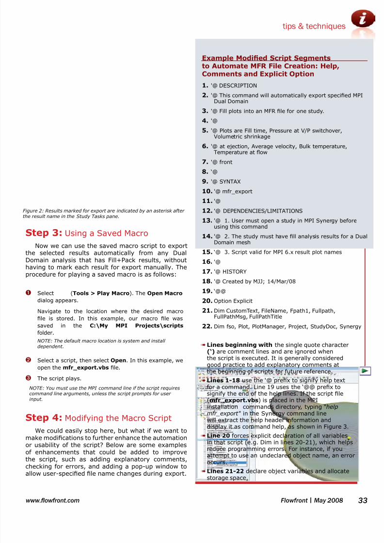
7/27/2019 Flowfront 2008may Lr
http://slidepdf.com/reader/full/flowfront-2008may-lr 33/40
www.owfront.com 33Flowfront | May 2008
Figure 2: Results marked for export are indicated by an asterisk afterthe result name in the Study Tasks pane.
tips & techniques
Step 3: Using a Saved Macro
Now we can use the saved macro script to exportthe selected results automatically from any DualDomain analysis that has Fill+Pack results, withouthaving to mark each result for export manually. Theprocedure for playing a saved macro is as follows:
➊ Select (Tools > Play Macro). The Open Macro
dialog appears.
Navigate to the location where the desired macro
le is stored. In this example, our macro le was
saved in the C:\My MPI Projects\scripts
folder.
NOTE: The default macro location is system and installdependent.
➋ Select a script, then select Open. In this example, we
open the mfr_export.vbs le.
➌ The script plays.
NOTE: You must use the MPI command line if the script requirescommand line arguments, unless the script prompts for userinput.
Step 4: Modifying the Macro Script
We could easily stop here, but what if we want tomake modications to further enhance the automationor usability of the script? Below are some examplesof enhancements that could be added to improvethe script, such as adding explanatory comments,checking for errors, and adding a pop-up window to
allow user-specied le name changes during export.
Lines beginning with➠ the single quote character(‘) are comment lines and are ignored whenthe script is executed. It is generally consideredgood practice to add explanatory comments atthe beginning of scripts for future reference.
Lines 1-18➠ use the ‘@ prex to signify help textfor a command. Line 19 uses the ‘@@ prex tosignify the end of the help lines. If the script le(mfr_export.vbs) is placed in the MPIinstallation commands directory, typing "helpmfr_export " in the Synergy command linewill extract the help header information anddisplay it as command help, as shown in Figure 3.
Line 20➠ forces explicit declaration of all variablesin that script (e.g. Dim in lines 20-21), which helpsreduce programming errors. For instance, if youattempt to use an undeclared object name, an erroroccurs.
Lines 21-22➠ declare object variables and allocate
storage space.
Example Modied Script Segmentsto Automate MFR File Creation: Help,Comments and Explicit Option
'@ DESCRIPTION1.
'@ This command will automatically export specied MPI2.Dual Domain
'@ Fill plots into an MFR le for one study.3.
'@4.
'@ Plots are Fill time, Pressure at V/P switchover,5.Volumetric shrinkage
'@ at ejection, Average velocity, Bulk temperature,6.Temperature at ow
'@ front7.
‘@8.
'@ SYNTAX9.
'@ mfr_export10.
'@11.
'@ DEPENDENCIES/LIMITATIONS12.
'@ 1. User must open a study in MPI Synergy before13.using this command
'@ 2. The study must have ll analysis results for a Dual14.Domain mesh
‘@ 3. Script valid for MPI 6.x result plot names15.
'@16.
'@ HISTORY17.
'@ Created by MJJ; 14/Mar/0818.
‘@@19.
Option Explicit20.
Dim CustomText, FileName, Fpath1, Fullpath,21.FullPathMsg, FullPathTitle
Dim fso, Plot, PlotManager, Project, StudyDoc, Synergy22.

7/27/2019 Flowfront 2008may Lr
http://slidepdf.com/reader/full/flowfront-2008may-lr 34/40
Flowfront | May 200834 www.owfront.com
tips & techniques
Line 23➠ initializes the Plot object with the Fill timeresult. Any available result plot name can replacethe Fill time text to change the result retrieved.This is useful to know if you want a different set ofresults exported than those used in this example, orif the result name changes in a future MPI release.
Line 24-27➠ is an If statement that checks if a Filltime result exists in the study. If it does not,
Nothing is returned and a message box titledERROR pops up and displays the message textshown in line 25.
Line 26➠ quits the script.
Line 28➠ initializes the Project object with the most
recent Synergy project.Line 29➠ populates the CustomText object with userinput generated from a pop-up input box withguided instructions.
Alternatively we could have used this line to obtain the userspecied full path location and *.mfr le name for saving (e.g.C:\Temp\MFR_Export\ll.mfr).
Line 30➠ initializes the fso le system object.
Line 31➠ uses the fso object to obtain the currentMPI project directory the active study is in.
Line 32➠ populates the Fullpath object with anassembly of the project directory and user enteredexport le name (e.g. CustomText object contents).
Line 33➠ exports the selected results to the userdened mfr le in the current project directory.
Line 34➠ populates the FullPathMsg object with a
message indicating where the le was stored.o Vbcrlf is a Visual Basic Carriage Return Line Feed whichsimply moves to the next line.
Line 35➠ populates the FullPathTitle object with text.
Line 36➠ uses the MsgBox function to display amessage box with the text in line 34 and the titletext from line 35.
Step 5: Test-drive a Script
A fully functional version of the modied scriptdescribed in this article is available to registered MPIcustomers on the MPI Community Center web site in
the Training Material > Macro Exchange - Scripts area; select Export MFR ll results to a le.Download this script onto your local computer and useStep 3 to try it out for yourself.
NOTE: Moldow Results les exported from MPI 6.2must be viewed with Moldow Communicator 2.0.
Extensive documentation and more examples ofusing the API can be found in the MPI Help (Help> Search Help > Contents (tab) > ApplicationProgramming Interface (API) or Help > Tutorials> Automating MPI. ■
Figure 3: Command line help example
Results Availability Check
Set Plot = PlotManager.FindPlotByName("Fill time")23.
If Plot Is Nothing Then24.
MsgBox "No Fill time plot in result set",, "ERROR"25.
WScript.Quit26.
End If 27.
Change Export File Name
Set Project = Synergy.Project()28.
CustomText = InputBox("Enter the le name29.for the exported MFR le without anextension:” & vbcrlf & “EX: ll.mfr", "ExportMFR File Name")
Set fso = CreateObject("Scripting.30.
FileSystemObject")
Fpath1 = fso.GetAbsolutePathName(".")31.
Fullpath = Fpath1 & "\" & Customtext32.
Project.Export Fullpath, True, True33.
FullPathMsg = "The MFR le was successfully34.saved in:" & vbcrlf & Fullpath
FullPathTitle = "MFR Export Successful!"35.
MsgBox FullPathMsg,,FullPathTitle36.
L e a r n m o r e T i p s & T e c h n i q u e s ❙ Visit the MPI Community Center or MPA Community Center today. Registered customers will nd Hints and
Tips articles, user discussion forums, known bugs and limitations, and a host of other valuable information.

7/27/2019 Flowfront 2008may Lr
http://slidepdf.com/reader/full/flowfront-2008may-lr 35/40
www.owfront.com 35Flowfront | May 2008
The products we develop must satisfy a varietyof criteria, be aesthetically pleasing, functionalover the product’s service life, safe, economical
and they must be manufacturable. Historically, plas-tics products, like many other products, have beendeveloped using the so called “Over the Wall Approachto Design”. In many ways, it is human nature thatthe designers of new products want their own ideasto drive the development. In reality however, this ap-proach to product development does not lead to themost efcient product designs, at least not in a timelymanner. This series and compartmentalized approachto design, where there is limited communications be-tween the various professionals involved in the de-velopment process, is common. Those involved inthe early upstream concept stages of design, such asindustrial design, establish the shapes that the engi-neers, tooling designers and manufacturing engineersmust bring to fruition. In many cases, the part ge-ometries established by the industrial designers andthe product designers are in fact found to be difcultor impossible to manufacture once these proposedpart designs reach the eyes of the tooling designer.In such a case, the tooling designer will recommendchanges and a more manufacturing friendly designcan be jointly developed. However, it should be noted
that the x-axis in gure 1 is time, and movement tothe left along the x-axis is wasted time. Delays innew product development are almost always tracedback to a lack of coordination between various partiesinvolved in the product development process.
The solution to this all too common problem is notcomplicated. It is simply a matter of managementphilosophy. The same product development groupsshown in gure 1 must function more like a teamwith greatly improved communications. Conceptually, “Concurrent Engineering” as it is commonly called,is like putting all of the professionals involved in theproduct development process in one room, with no
walls between them. When the industrial designer
or the product designer propose a geometry, themanufacturing engineer or the tooling designer canweigh in immediately and bring manufacturing issuesto the forefront before detailed designs are developed.This improved communications leads to more well-balanced product designs that are achieved in a muchmore timely manner. There are no surprises as theproduct develops because everyone involved in theproduct development process has had input into thekey design decisions.
While the concept of concurrent engineering is wellunderstood, it is not easily implemented in practice,largely for one very understandable reason. Lookingback many years, there were days when very largecorporations did in fact employ all of the professionsinvolved in new product development. Some companies
did employ designers, mold makers, tool builders, anddid molding/manufacturing in house. In such a case,it would be relatively easy to literally put everyoneinvolved in the same room. Such a business model israre today. The reality today is that for the most part,corporations run lean. The use of vendors for each ofthese product development functions is the norm, forgood or bad. The advantages of vendor-based productdevelopment are numerous in terms of economics andproduct quality when managed effectively. Vendorsthat possess capabilities closely matched to the newproduct can be utilized. However, from a concurrentengineering perspective, the logistics of bringing
all of these people together, in the same room, soto speak, becomes an issue. In some ways, it is
Developing new plastic products is always aninteresting challenge that can be approachedin a variety of different ways.
Taking Concurrent EngineeringOne Step Further: Consider Recycling
B Y ROBERT MALLOY , PROFESSOR, UNIVERSITY OF MASSACHUSETTS LOWELL
perspective

7/27/2019 Flowfront 2008may Lr
http://slidepdf.com/reader/full/flowfront-2008may-lr 36/40
Flowfront | May 200836 www.owfront.com
perspective
Are you Moldow Certied?
Moldow certication is the global industry standard for pro-
ciency in the use of Moldow Plastics Insight (MPI) software.
Analysts can progress through three levels of individual certi-
cation–Bronze, Silver and Gold. Company-level certication is
also available.
For more information about Moldow certication and training services,
contact Matthew Jaworski, Training Services Manager:
E-mail: [email protected] Tel: +1 814.460.5097
Why Become Certied?
Promote your organization as more➠ procient than
your competitors
Earn more respect from colleagues and managers➠
Realize potential for advancement opportunities➠
Further your technical expertise as an analyst➠
Make the most out of your software investment➠
MarketingProduct
Engineering
E = σ / ε
Tooling ManufacturingIndustrialDesign Consumer
$
Recycling
Figure 1
Marketing
ProductEngineering
E = σ / ε
Tooling
Manufacturing
Industrial Design
Consumer
$
Recycling
TIME
Figure 2

7/27/2019 Flowfront 2008may Lr
http://slidepdf.com/reader/full/flowfront-2008may-lr 37/40
www.owfront.com 37Flowfront | May 2008
actually much easier to be in the same “virtualroom” today thanks to the wonders of internet-basedcommunications. However, this can only happen whenproject managers make sure this does happen. Thesingle most important action is to identify all vendors
involved in the project up front and ensure that thelines of communication are well established. Thepractice of designing products and then going out fortool bids is the ultimate example of the over the wallapproach to new product development. If concurrentengineering is to be practiced, designers, by denition,must have the ability to run their ideas past toolingand manufacturing groups before their designs arenalized.
The concurrent engineering and design conceptsdescribed above are well known and well established.But perhaps we need to take this concept of concurrentengineering one step further in terms of designing
new products in a more environmentally friendlymanner. The products we design today, with veryfew exceptions, have been designed with little or noinput from anyone who needs to deal with the productafter it is used by the consumer. The plastic productswe design and manufacture today will all have someimpact on our environment after their useful servicelife has expired. Landlling, incineration, composting(in the case of biodegradable or compostable plastics),reuse and recycling are all possibilities. Recycling insome way, shape, or form, is clearly an admirable goalfor any new product. If we design and develop newplastics products without consulting the “recycler”, we
are guilty of practicing the over-the-wall approach todesign as it relates to the environment. The designof a product has a very signicant impact on therecyclability of the product. It is important to notethat designers do not determine if a product will in factbe recycled, but designers do have a direct impact onthe “ease” of recycling a product, which does impactthe likelihood of recycling.
Like concurrent engineering itself, thisenvironmental design concept is simple; bring therecycler into the room when new products aredeveloped, so that they can provide their insightwhen important design decisions are made. As withany input, the project leader may choose to take orignore the advice, but at least an informed decisioncan be made with respect to potential recyclability.The primary objective of the product designer is todesign a functional product economically, but if theproduct can also be more easily recycled, that is aplus. Even very simple design changes can have avery signicant impact on the recyclability of a product.Materials of construction, ease of disassembly, coding,methods of decorating are but a few of the importantareas of concern. Replacing screws and inserts on anelectronics enclosure with snap ts would make theenclosure more recyclable. The recyclability shouldnot be the sole factor in driving the design but should
be taken into consideration as a factor. Likewise, if
several materials were being considered for a newplastics part, and one was more recyclable than theothers, that should be considered along with othermaterial properties being considered.
The concept of involving the recycler when making
major design decisions is simple, but the practice ofdoing so is not as easily implemented in most casesfor one simple reason. The “recycler” is not alwayseasily identied. In a limited number of cases, wherethe plastics recycling infrastructure is well established,it is a reasonable expectation to include the recycleras part of the product development team becausethe recycler is easily identied. Designers of HDPEbottles can look to trade associations and commercialrecyclers for guidance without difculty. However, thelimited plastics recycling infrastructure means thatdesigners of most plastic products, even designers whohave the desire to consider the recyclers input, may
not have the option to do so. As we move forward intime, the plastics recycling infrastructure will continueto develop, and the simple concept of involving therecycler in the early stages of product developmentwill hopefully become more of a widespread reality. ■
Currently serving as the Department Chair at the University ofMassachusetts Lowell, Prof. Malloy remains an active educator andresearcher in the areas of plastics product design, polymer processing,recycling of thermoplastics. UML now offers on-line graduate classesin plastics. Go to http://plastics.uml.edu.
perspective

7/27/2019 Flowfront 2008may Lr
http://slidepdf.com/reader/full/flowfront-2008may-lr 38/40
Advertiser Index
Company URL Page
Lenovo www.lenovo.com 2Altair Hyperworks www.altairhyperworks.com 3
ANSYS www.ansys.com 4
Moldow Corporation www.moldow.com 6
CAE Services www.caeservices.com 15
Plastics Engineering Group www.pe-group.de 15
SolidWorks Corporation www.solidworks.com 16
Esteco www.esteco.com 17
Noran Engineering, Inc. www.neinastran.com 24
Bozilla Corporation www.bozillacorp.com 24
Hoff & Associates www.hoff.com 30
DatapointLabs www.datapointlabs.com 37
HP www.hp.com 39
Microsoft www.microsoft.com/hpc BC
Editorial Index
Company URL Page
Altair Engineering, Inc. www.altair.com 10Optical Research Associates www.opticalres.com 10
Jaguar www.jaguar.com 14
Promold www.promold.fr 16
Valeo www.valeo.com 16
Renault www.renault.com 16
Microsoft Corporation www.microsoft.com 19
Ford Motor Company www.ford.com 22
OEM/Erie, Inc. www.oemerie.com 23
SABIC Innovative Plastics www.sabic.com 23
Mack Molding Comany www.mack.com 25
University of Massachusetts Lowell www.uml.edu 35
If your company is using a uniqueapproach to design or manufacture
injection-molded parts, we’d likehear about it, and potentiallyinform our readers.
There may also be potential to havean article on our web site, or have youspeak at our next user group meeting.
For more information, please contact:
Case Studies
Wanted!
Brian Sather+1 508.358.5848, x289
For advertising information, please contact Melissa Aytek:Tel: +1 508-358-5848 x258, E-mail: [email protected], click Advertise.

7/27/2019 Flowfront 2008may Lr
http://slidepdf.com/reader/full/flowfront-2008may-lr 39/40

7/27/2019 Flowfront 2008may Lr
http://slidepdf.com/reader/full/flowfront-2008may-lr 40/40
The supercomputing power of high-performance computing (HPC) is now available
on a Microsoft® platform with Windows® Compute Cluster Server 2003. Work more
efficiently with Moldflow® Enterprise-Enabled Simulation solutions in a familiar
Windows environment.
Microsoft is taking HPC further with easy cluster management, enhanced
collaboration, and common client and cluster development tools.
Great performance. Better efficiency. Accelerated time to insight.
The next generation of HPC is here.
Harness the power of Microsoft and Moldflow technology.