Flowfield Analysis of a Small Entry Probe (SPRITE) Tested ...
17
American Institute of Aeronautics and Astronautics 1 Flowfield Analysis of a Small Entry Probe (SPRITE) Tested in an Arc Jet Dinesh K. Prabhu 1 ERC, Inc., NASA Ames Research Center, Moffett Field, CA 94035 Results of simulations of flow of an arc-heated stream around a 14-inch diameter 45° sphere-cone configuration are presented. Computations are first benchmarked against pressure and heat flux measurements made using copper slug calorimeters of different shapes and sizes. The influence of catalycity of copper on computed results is investigated. Good agreements between predictions and measurements are obtained by assuming the copper slug to be partially catalytic to atomic recombination. With total enthalpy estimates obtained from these preliminary computations, calculations are then performed for the test article, with the nozzle and test article considered as an integrated whole – the same procedure adopted for calorimeter simulations. The resulting heat fluxes at select points on the test article (points at which fully instrumented plugs were placed) are used in material thermal response code calculations. Predicted time histories of temperature are compared against thermocouple data from the instrumented plugs, and recession determined. Good agreement is obtained for in-depth thermocouples. Nomenclature c = mass fraction C H = film coefficient D b = base diameter of the small probe (in) H = specific total enthalpy (MJ/kg) K = correlation constant in simplified Fay-Riddell formula (kg/m 3/2 .s.√atm) L b = axial length of the test article (in) M = Mach number m = mass flow rate of air (gm/s) p = pressure (kPa) q = heat flux (W/cm 2 ) R c = aft shoulder radius of the test article (in) R b = base radius of the test article (in) R eff = effective nose radius of the non-hemispherical calorimeter body (in) R n = nose radius of the test article, or nose radius of the calorimeter body (in) R s = fore shoulder radius of the test article (in) r = radial coordinate (in) T = temperature (°C or K) V = velocity (m) x = roll axis y = pitch axis z = yaw axis, radial coordinate Greek letters ε = emissivity θ a = aft cone half angle (deg) θ f = fore cone half angle (deg) ρ = mass density (kg/m 3 ) σ = sonic flow parameter (s/m) 1 Senior Research Scientist, Aerothermodynamics Branch, Mail Stop 230-3. Associate Fellow AIAA.
Transcript of Flowfield Analysis of a Small Entry Probe (SPRITE) Tested ...

American Institute of Aeronautics and Astronautics
1
Flowfield Analysis of a Small Entry Probe (SPRITE) Tested in an Arc Jet
Dinesh K. Prabhu1 ERC, Inc., NASA Ames Research Center, Moffett Field, CA 94035
Results of simulations of flow of an arc-heated stream around a 14-inch diameter 45° sphere-cone configuration are presented. Computations are first benchmarked against pressure and heat flux measurements made using copper slug calorimeters of different shapes and sizes. The influence of catalycity of copper on computed results is investigated. Good agreements between predictions and measurements are obtained by assuming the copper slug to be partially catalytic to atomic recombination. With total enthalpy estimates obtained from these preliminary computations, calculations are then performed for the test article, with the nozzle and test article considered as an integrated whole – the same procedure adopted for calorimeter simulations. The resulting heat fluxes at select points on the test article (points at which fully instrumented plugs were placed) are used in material thermal response code calculations. Predicted time histories of temperature are compared against thermocouple data from the instrumented plugs, and recession determined. Good agreement is obtained for in-depth thermocouples.
Nomenclature c = mass fraction CH = film coefficient Db = base diameter of the small probe (in) H = specific total enthalpy (MJ/kg) K = correlation constant in simplified Fay-Riddell formula (kg/m3/2.s.√atm) Lb = axial length of the test article (in) M = Mach number m = mass flow rate of air (gm/s) p = pressure (kPa) q = heat flux (W/cm2) Rc = aft shoulder radius of the test article (in) Rb = base radius of the test article (in) Reff = effective nose radius of the non-hemispherical calorimeter body (in) Rn = nose radius of the test article, or nose radius of the calorimeter body (in) Rs = fore shoulder radius of the test article (in) r = radial coordinate (in) T = temperature (°C or K) V = velocity (m) x = roll axis y = pitch axis z = yaw axis, radial coordinate Greek letters ε = emissivity θa = aft cone half angle (deg) θf = fore cone half angle (deg) ρ = mass density (kg/m3) σ = sonic flow parameter (s/m)
1 Senior Research Scientist, Aerothermodynamics Branch, Mail Stop 230-3. Associate Fellow AIAA.

American Institute of Aeronautics and Astronautics
2
Subscripts Air = primary flow stream Air+ = secondary flow stream (“add air”) in the plenum Ar = argon arc = arc column bulk = bulk quantity in the plenum (i.e., mass-averaged value) cal = calorimeter CL = centerline e = boundary-layer edge hemi = hemisphere stag = stagnation point throat = nozzle throat w = wall Acronyms AHF = aerodynamic heating facility ARC = Ames Research Center CFD = computational fluid dynamics DS2 = Deep Space 2 DAS = data acquisition system EB2 = enthalpy by energy balance HEAT = Hollow aErothermal Ablation and Temperature IHF = interaction heating facility LSAT = large-scale article test MSL = Mars Science Laboratory OML = outer mold line PICA = phenolic impregnated carbon ablator RTV = room temperature vulcanizing SPORE = Small Probes for Orbital Return of Experiments SPRITE = Small Probe Re-entry Investigation of TPS Engineering TTT = through the thickness
I. Introduction n an effort to fulfill a ‘test what you fly’ paradigm,1,2 a 14-inch diameter entry probe named Small Probe Re-entry Investigation of TPS Engineering (SPRITE) has been developed at NASA Ames Research Center. It is envisaged
that this class of small probes, with suitably tailored trajectories, will serve as robotic flight test beds for TPS materials3 or perhaps even other vehicle subsystems (the SPRITE design is quite flexible). With some modifications, the same small probe design could also be used to return biological samples from orbit, which is the prime objective of the Small Probes for Orbital Return of Experiments (SPORE) project led out of Georgia Institute of Technology.4
As a first step towards establishing the feasibility of the ‘test what you fly’ paradigm, a full-scale (14-inch diameter) model of SPRITE was tested in the 18-inch nozzle of the Aerodynamic Heating Facility (AHF), an arc jet, at NASA Ames Research Center. This series of arc jet tests for SPRITE was a follow-on to the LSAT or Large-Scale Article Test5 performed in the NASA ARC 60 MW Interaction Heating Facility (IHF) in late 2008/early 2009, and the test of a full-scale red oak model of DS2 or Deep Space-26 in the NASA ARC 20 MW Aerodynamic Heating Facility (AHF) in late 2009/early 2010. There were no issues with mass capture by the diffusers in either facility (AHF or IHF) for blunt bodies up to 15 inches in diameter. Of course, large nozzles (18- and 21-inch exit diameter) had to be used in testing articles of this size.
Building on this initial success with large-scale articles, two identical models (SPRITE-T1-1 and SPRITE-T1-2 – T1 indicating the choice of back shell geometry) were fabricated and tested in the AHF with the 18-inch nozzle installed.7,2 Both these test articles were 14 inches in diameter and had a 45° sphere-cone forebody (like DS2) made of PICA (Phenolic Impregnated Carbon Ablator) bonded on to a 1/8th-inch thick aluminum shell using RTV adhesive. The aft portion of the test article was a conical frustum (15° cone angle) with LI-2200 bonded on to the aluminum shell. The PICA shell had a thickness of 1 inch over the frustum and 1.36-inch thick on the spherical nose cap, while the LI-2200 tiles on the aft shell were 0.7-inch thick. Each model was fully instrumented with (a) 3 in-depth thermocouples and a HEAT sensor8 imbedded in 1.3-inch diameter plugs in the heat shield (similar to those used on the heatshield of the Mars Science Laboratory or MSL9), (b) several thermocouples bonded to the aluminum
I

American Institute of Aeronautics and Astronautics
3
substructure, and (c) a few strain gauges. Data from the strain gauges and some of the thermocouples and gauges were acquired by the on-board data acquisition system (DAS),10 while data from the other thermocouples were routed to the facility-provided DAS, thereby enabling a cross check on the in situ measurement capability. Apart from the primary objective of testing flight-scale articles in an arc jet, the experiments also served the purpose of demonstrating the feasibility of in situ measurements of temperature, strain and recession using a data acquisition system integrated internally with the test article.
Modeling and simulation have been an integral part of the SPRITE arc jet experiments, and were used in test planning and post-test analysis. For instance, pre-test flow field computations were performed to assess flow blockage issues (if any).7 Results from these computations were used in estimating the time of exposure of the test article to the arc-heated stream so that the internal temperature of the probe would not exceed the constraint of battery operation of the internal data acquisition system.11 The combination of simulations tools – primarily DPLR12, FIAT13, and MARC14 – were then used in post-test analyses in order to verify/validate these tools against actual measurements.
The present paper also provides details of the process used in simulation of the flow of an arc-heated stream expanded through a conical convergent-divergent nozzle over a test body (calorimeter or the test article). The primary objectives of the DPLR-based simulation process15 are: (1) to assess if there are blockage issues with candidate test geometries, (2) to provide initial heating distributions over the test article so that thermal-structural analyses can be performed to estimate the required exposure time, (3) to provide post-test heating estimates, based on as-run conditions of the arc heater, for final thermal-structural analysis, and (4) to determine the thermal response (in-depth thermal environments and/or recession, if any) of the materials used on the fore and aft shells of the test geometry. In addition, these arc jet tests could facilitate a better understanding of the surface catalycity of copper, the material used in calorimetry.
II. Test Geometry The test geometry is a 45° sphere-cone of 14 inches base diameter (i.e., Rb = 14 in). The geometry is shown in a
coordinate system centered on the nozzle exit plane (NEP) (Fig. 1). The nose radius, Rn, is 4 inches, and the radii of the two shoulders, Rs and Rc (fore and aft), are 0.4 and 0.25 inch, respectively. The conical frustum of the aft shell has a 15° inclination to the horizontal, and the total axial length, Lb, of the test article is 11 inches. Also shown in Fig. 1 are the locations of the instrumented plugs used in the test. The locations of the plugs are approximate and measured from the tangency points of the front conical frustum and the shoulder torus. For the purpose of CFD analysis, i.e., prediction of surface aerothermal environments (pressure, heat flux, and shear), only the outer mold line (OML) of the test article is necessary; the time-varying distribution of heat through the thickness of the materials that make up the test article is determined by a materials thermal response code such as FIAT13 or a thermal-structural analysis code such as MARC,14 with the CFD prediction of environments as boundary conditions.
Figure 1. SPRITE-T1 geometry tested in the 18-inch nozzle of the 20 MW Aerodynamic Heating Facility (AHF). The apex of the model is located 12 inches from the nozzle exit plane (NEP).

American Institute of Aeronautics and Astronautics
4
III. Pre-Test Computations Testing at large scale (12 to 14-inch diameter test articles) provides meaningful spatial development of a
boundary layer on the wetted acreage as compared to the 4-inch diameter test articles (usually simple shapes like flat-faced cylinders, or hemispheres, or iso-q) that form the basis of typical stagnation point testing in the ARC arc-heated facilities. However, the facility dimensions (nozzle and diffuser) place an upper bound on the projected diameter of the test article, with flow blockage, i.e., inability of the diffuser to capture the mass flow, being the primary consideration.
A simple way of establishing the model size limit is to build wooden models (of different sizes) and expose them to an arc-heated stream. Such a procedure poses some risk to the facility. A simpler way than the build-and-test approach, and a quicker one, is to run a number of CFD simulations with models of different shapes/sizes, and thereby determine the maximum size for which the diffuser is still able to capture the flow. A single wooden replica of the final shape then needs to be exposed to the arc-heated stream to establish that testing at that scale can be accomplished safely in the facility. This simpler CFD-based approach was chosen in the design of the successful LSAT5 conducted in the 21.5-nozzle of the IHF, and the same approach was taken for the design of the SPRITE test article as well. The SPRITE test article was designed for the 18-inch nozzle of the AHF.
The CFD process, built around v3.05 of DPLR,12 is documented in the paper of Prabhu et al.15 Briefly, the simulation process treats the problem as a gas dynamic one and excludes the constrictor arc heater. The arc-heated gas mixture of air and argon is assumed to be in thermochemical equilibrium at the inlet to the convergent-divergent nozzle, and inflow profiles of species mass densities, temperature, and velocities are estimated using an in-house software utility called NOZZLE_THROAT_CONDITIONS,16 which uses CEA17 as the equilibrium computational engine. This utility requires the flow rates of air and argon, the bulk enthalpy of the arc-heated gas mixture, and an estimate of the Mach number at the inlet. Computations are then performed with the inflow profiles prescribed as pointwise boundary conditions in DPLR. The computational domain includes the convergent-divergent nozzle, the test article, and part of the diffuser. Since the methodology considers flow non-uniformities (if any) to occur in the radial direction only, the axisymmetric version of the CFD process suffices for axisymmetric test articles.
In the pre-test computations, the SPRITE geometry was identical to the DS2 flight vehicle – the 45° sphere-cone forebody had a base diameter of 13.8 inches, and the aft shell was a section of a sphere (required for stability in the low supersonic through subsonic portion of flight). Calculations were performed for the AHF operating at conditions close to its maximum – a current of 2000 A and an air-argon total mass flow rate of 360 gm/s. At these conditions, the arc column develops a pressure of 814 kPa. Figure 2 shows pitch plane contours of Mach number obtained from the computations. Clearly, the diffuser captures the test article bow shock, and there are no issues related to flow blockage for a 14-inch diameter test article. It should be noted here that blockage is not an issue because the 45° sphere-cone forebody sweeps the shock back. For sphere-cone geometries with larger cone angle, there could be a potential issue with a 14-inch diameter body.
Figure 2. Pitch plane contours of Mach number for the 18-inch nozzle of the AHF with a 14-inch diameter 45° sphere-cone geometry (DS2) placed at 12 inches from the nozzle exit plane.
Since computations indicated that there are no problems with testing a 14-inch diameter geometry in the 18-inch
nozzle of the AHF, a red oak model of the same geometry was constructed and exposed to an arc-heated stream. The
American Institute of Aeronautics and Astronautics
5
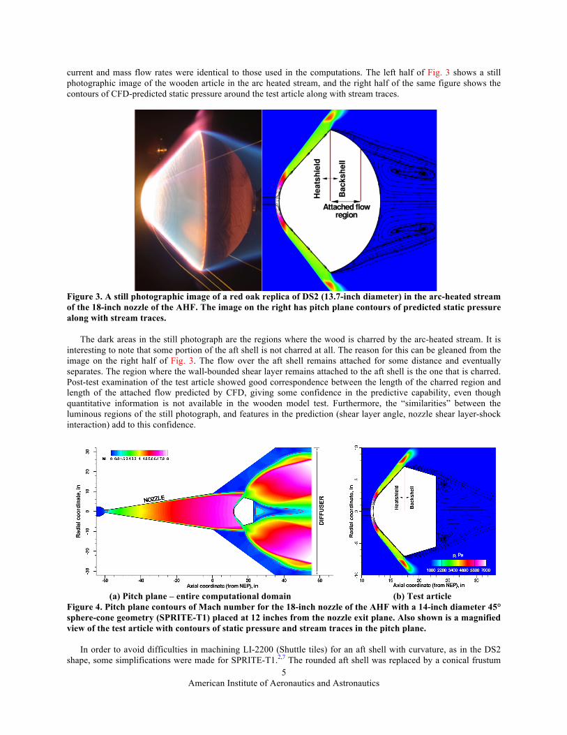
current and mass flow rates were identical to those used in the computations. The left half of Fig. 3 shows a still photographic image of the wooden article in the arc heated stream, and the right half of the same figure shows the contours of CFD-predicted static pressure around the test article along with stream traces.
Figure 3. A still photographic image of a red oak replica of DS2 (13.7-inch diameter) in the arc-heated stream of the 18-inch nozzle of the AHF. The image on the right has pitch plane contours of predicted static pressure along with stream traces.
The dark areas in the still photograph are the regions where the wood is charred by the arc-heated stream. It is
interesting to note that some portion of the aft shell is not charred at all. The reason for this can be gleaned from the image on the right half of Fig. 3. The flow over the aft shell remains attached for some distance and eventually separates. The region where the wall-bounded shear layer remains attached to the aft shell is the one that is charred. Post-test examination of the test article showed good correspondence between the length of the charred region and length of the attached flow predicted by CFD, giving some confidence in the predictive capability, even though quantitative information is not available in the wooden model test. Furthermore, the “similarities” between the luminous regions of the still photograph, and features in the prediction (shear layer angle, nozzle shear layer-shock interaction) add to this confidence.
(a) Pitch plane – entire computational domain (b) Test article
Figure 4. Pitch plane contours of Mach number for the 18-inch nozzle of the AHF with a 14-inch diameter 45° sphere-cone geometry (SPRITE-T1) placed at 12 inches from the nozzle exit plane. Also shown is a magnified view of the test article with contours of static pressure and stream traces in the pitch plane.
In order to avoid difficulties in machining LI-2200 (Shuttle tiles) for an aft shell with curvature, as in the DS2
shape, some simplifications were made for SPRITE-T1.2,7 The rounded aft shell was replaced by a conical frustum

American Institute of Aeronautics and Astronautics
6
(cone angle of 15° to the horizontal), and CFD computations were performed again for the new geometry. The flow conditions were the same as those used in the DS2 calculations. The results of the new computations are shown in Fig. 4. Pitch plane contours of Mach number in the entire computational domain are shown in Fig. 4a. Clearly, as in the DS2 case, SPRITE-T1 does not have any flow blockage issues. A magnified view of the test article with pitch plane contours of static pressure and stream traces is shown in Fig. 4b. The forebody flow for SPRITE-T1 is almost identical to that of the DS2 (Fig. 3b). The flow on the aft shell remains attached over the entire acreage, separating at the aft shoulder. The predicted surface pressure, heat flux, and shear distributions were used as initial conditions for detailed thermal-structural computations. These thermal-structural computations were performed to determine the rate of heat soak into the structure and determine a priori an estimate of the time of exposure for the actual arc jet model before the internal temperature exceeded a pre-set value. More details of the use of CFD predictions in thermal-structural computations can be found in the paper of Agrawal et al.11
IV. Computational Analysis and Results Two fully instrumented models of SPRITE-T1 were tested in the AHF (Entry 295) at NASA ARC. Flow field computations were necessary to reconstruct the pressure and heat flux environments experienced by the SPRITE article at actual test conditions. The axisymmetric simulation methodology developed by Prabhu et al.15 for the arc jets at NASA ARC requires as inputs (a) the mass flow rates of air and argon, and (b) the specific total enthalpy on the nozzle centerline. The mass flow rates were measured as part of the arc jet operations, while the measured pressures and heat fluxes at the stagnation point of calorimeters (of various shapes and sizes) were used to determine the specific total enthalpy on the nozzle centerline. More details of the measurements, including details of calorimetry, can be found in the paper of Skokova.7 A complete set of experimental data is now available for use in simulation of the flow field that develops in the nozzle and over the test article. The simulation procedure was originally developed around v3.05 of the in-house flow solver, DPLR, and one of the objectives of the present work is to upgrade the procedure with the latest version, v4.02.2,12 which offers a more stable option of a subsonic inflow boundary condition based on the method of characteristics. Detailed flow computations are performed first for the various calorimeters used in the test. Once the flow solver is calibrated to calorimeter measurements (pressure and heat flux), detailed computations are performed for the test article. The resulting heat flux and pressure are then provided as inputs to v2.6.1 of the materials thermal response code, FIAT.13
A. Flowfield Simulations The bulk enthalpy and total flow rate (along with mass fractions of N2, O2, and Ar) of the test are provided as inputs to the previously referenced NOZZLE_THROAT_CONDITIONS. This code, developed by Gökçen and Saunders,16 uses the CEA code17 (formerly called the Gordon-McBride code) as the computational engine; the arc-heated gas mixture can be assumed to be thermodynamic equilibrium on account of high pressure in the arc column. The resulting mixture mass density, velocity (obtained from the speed of sound and assumed Mach number), temperature, and mass fractions of the constituent species (N2, O2, NO, N, O, and Ar) are used as pointwise inflow conditions to DPLR. The computational domain consists of the entire convergent-divergent nozzle and the free jet in which a calorimeter or test article is inserted. The computational boundaries for the free jet (plus calorimeter) are truncated so that a supersonic extrapolation boundary condition can be applied to them. Further, the water-cooled nozzle wall and the surface of the copper calorimeter are assumed to be at a constant temperature of 400 K (127 °C), and fully catalytic to atom recombination.
B. Simulations of Calorimeters: Round 1, DPLR v3.05 In the first round of simulations, only calorimeters are considered. Computational grids for the calorimeter
geometries of AHF 295 had already been created and tested in pre-test computations. The grid block corresponding to each of the calorimeters was adapted to the bow shock, and the wall-normal spacing controlled so as to achieve a cell Reynolds number of O(1) over the calorimeter. The in-house code SAGE18 was used for the adaption of the grid block around the calorimeter.
The computed values of pressure and cold-wall heat flux at the stagnation point of each calorimeter are given in Table 1. Also shown in the table are the effective radii of each non-hemispherical calorimeter, using the 4-inch hemispherical calorimeter as the reference.

American Institute of Aeronautics and Astronautics
7
Table 1. Computational predictions of pressure and cold-wall heat flux at the stagnation point using DPLR v3.05 Experimenta CFD (DPLR v3.05), Hbulk = 13.7 MJ/kg
pstag qstag Reffc pstag qstag Diff. from expt. Reff
c Calorimeter kPa W/cm2 in kPa W/cm2 Pressure
kPa Heat flux
W/cm2 in
4in Hemi 8.3 222.0 2.0 7.99 264.9 -3.5% +19.3% 2.0 4in Iso-q 8.4 167.8 3.501 8.08 190.1 -3.6% +13.3% 3.884 4in Flat Face 8.3 123.0 6.515 8.14 129.5 -1.9% +5.3% 8.369 6in Flat Faceb 8.5 98.0 10.263 8.26 102.7 -2.8% +4.8% 13.306 aArithmetic average of all measurements bResults for center slug only cResults using the hemispherical calorimeter as the reference in both experiment and CFD
Although the agreement between computation and experiment is excellent for the flat-faced calorimeters, the
disagreement for the calorimeters with surface curvature is large. This disagreement is even more disconcerting given that the experimental data appear to be internally consistent – they all yield nearly similar values for centerline enthalpy and effective radius computed for each non-hemispherical calorimeter (using the hemispherical one as the reference).
Additional computations were performed for the hemispherical and iso-q calorimeters with flat-faced slugs (sensing surface) of 0.38-inch diameter, i.e., exposed faces of the copper slugs at the stagnation point were assumed to have zero curvature (or equivalently, an infinite radius of curvature). The pressure and heat flux distributions for the 4 calorimeters – hemispherical, iso-q, and flat-face cylindrical – are shown in Fig. 5. Also shown (as dashed lines) are the distributions for the hemispherical and iso-q calorimeter with flat-faced slugs. Clearly, the assumption of curvature mismatch, i.e., a flat-faced slug in a spherical section, does not help much to improve the accuracy of predictions. At best, the assumption of a flat-faced slug decreases the predicted heat flux by about 5%. The error bars (±5% for pressure, and ±15% for cold-wall heat flux) shown in the figure are somewhat arbitrary in that they do not represent actual measurement errors, and are based on estimates provided by experienced arc jet test engineers. They are only meant to provide a relative measure of calorimeter performance.
(a) Pressure (b) Cold-wall heat flux
Figure 5. Pressure and cold-wall heat flux distributions over various calorimeters employed in AHF 295. The symbols represent experimental data, but the ±15% error bars shown are assumed estimates of performance of a calorimeter, and meant to provide a basis for discussion. For pressure, the assumed error bars are ±5%.
Based on these results, one is thus left with the uncomfortable situation of predictions in excellent agreement for some, but not all, calorimeters. Given the number of free parameters – inflow Mach number, wall temperature,

American Institute of Aeronautics and Astronautics
8
surface catalysis, etc. – an attempt has been made to upgrade the simulation procedure to the latest version (v4.02.2) of DPLR, which has added new features. These results are discussed next.
C. Simulations of Calorimeters: Round 2, DPLR v4.02.2 Version 4.02.2 of DPLR offers a new feature of being able to specify a stagnation pressure and temperature for a
subsonic inflow boundary, and uses the method of characteristics in conjunction with the assumption of isentropic flow. This should be contrasted with the procedure adopted in v3.05, where an inflow Mach number was specified and the inflow boundary was considered to be fixed (invariant in time). The inflow Mach number was determined approximately, and the Dirichlet boundary condition specifies more than the number of requisite variables, which could result in non-conservation of mass.
As a first step towards handing off the process from v3.05 to v4.02.2 of DPLR, computations were performed for the 4-inch hemispherical calorimeter. The inflow conditions of v3.05 were used in v4.02.2, but the inflow Mach number was allowed to float. The resulting predictions of distributed surface temperature and cold-wall heat flux are shown in Fig. 6.
(a) Pressure (b) Cold-wall heat flux
Figure 6. Pressure and cold-wall heat flux distributions, obtained using v3.05 and v4.02.2 of DPLR for a 4-inch hemispherical calorimeter at AHF 295 conditions.
The preliminary conclusion from this one-off computation is that the agreement in predictions of v3.05 and v4.02.2 of DPLR is fair. However, the reduction of one free parameter (inflow Mach number) in simulations is the primary motivator for wanting to switch to the newer version. In the simulation process based on v3.05 of DPLR, the inflow Mach number assumed at the nozzle inlet is usually 0.053 – based on simple application of gas dynamic equations, while the subsonic inflow boundary condition used in v4.02.2 yields a value of 0.0538, which is 1.5% higher. Despite the small difference in inflow Mach, one should realize that the Mach number is subsonic and has significant influence (≈5%) on stagnation pressure (Fig. 6a).
D. Simulations of Calorimeters: Round 3, DPLR v4.02.2, Catalycity effect study It should be noted that even with the elimination of the inflow Mach number as an uncertainty there is no
improvement in the predicted level of heating at the stagnation point, and therefore another explanation should be sought. The surface temperature at the stagnation point of the test article (SPRITE-T1) was monitored using IR pyrometers during Run 3 of AHF295. The time traces shown in Fig. 7 perhaps provide a clue.
American Institute of Aeronautics and Astronautics
9
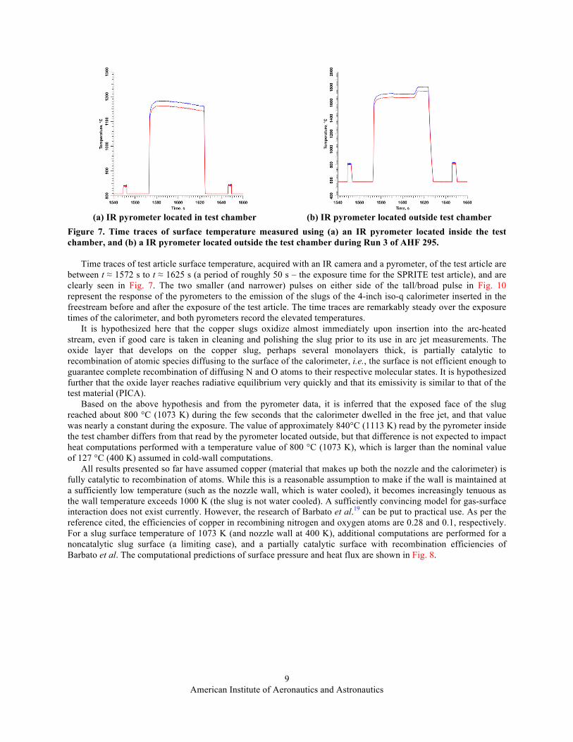
(a) IR pyrometer located in test chamber (b) IR pyrometer located outside test chamber
Figure 7. Time traces of surface temperature measured using (a) an IR pyrometer located inside the test chamber, and (b) a IR pyrometer located outside the test chamber during Run 3 of AHF 295.
Time traces of test article surface temperature, acquired with an IR camera and a pyrometer, of the test article are between t ≈ 1572 s to t ≈ 1625 s (a period of roughly 50 s – the exposure time for the SPRITE test article), and are clearly seen in Fig. 7. The two smaller (and narrower) pulses on either side of the tall/broad pulse in Fig. 10 represent the response of the pyrometers to the emission of the slugs of the 4-inch iso-q calorimeter inserted in the freestream before and after the exposure of the test article. The time traces are remarkably steady over the exposure times of the calorimeter, and both pyrometers record the elevated temperatures.
It is hypothesized here that the copper slugs oxidize almost immediately upon insertion into the arc-heated stream, even if good care is taken in cleaning and polishing the slug prior to its use in arc jet measurements. The oxide layer that develops on the copper slug, perhaps several monolayers thick, is partially catalytic to recombination of atomic species diffusing to the surface of the calorimeter, i.e., the surface is not efficient enough to guarantee complete recombination of diffusing N and O atoms to their respective molecular states. It is hypothesized further that the oxide layer reaches radiative equilibrium very quickly and that its emissivity is similar to that of the test material (PICA).
Based on the above hypothesis and from the pyrometer data, it is inferred that the exposed face of the slug reached about 800 °C (1073 K) during the few seconds that the calorimeter dwelled in the free jet, and that value was nearly a constant during the exposure. The value of approximately 840°C (1113 K) read by the pyrometer inside the test chamber differs from that read by the pyrometer located outside, but that difference is not expected to impact heat computations performed with a temperature value of 800 °C (1073 K), which is larger than the nominal value of 127 °C (400 K) assumed in cold-wall computations.
All results presented so far have assumed copper (material that makes up both the nozzle and the calorimeter) is fully catalytic to recombination of atoms. While this is a reasonable assumption to make if the wall is maintained at a sufficiently low temperature (such as the nozzle wall, which is water cooled), it becomes increasingly tenuous as the wall temperature exceeds 1000 K (the slug is not water cooled). A sufficiently convincing model for gas-surface interaction does not exist currently. However, the research of Barbato et al.19 can be put to practical use. As per the reference cited, the efficiencies of copper in recombining nitrogen and oxygen atoms are 0.28 and 0.1, respectively. For a slug surface temperature of 1073 K (and nozzle wall at 400 K), additional computations are performed for a noncatalytic slug surface (a limiting case), and a partially catalytic surface with recombination efficiencies of Barbato et al. The computational predictions of surface pressure and heat flux are shown in Fig. 8.

American Institute of Aeronautics and Astronautics
10
Figure 11. Influence of slug surface catalytic recombination efficiency on stagnation point pressure and heat flux for a 4-inch hemispherical copper slug calorimeter.
The results shown in Fig. 8 indicate that copper is likely to be partially catalytic and definitely not non-catalytic.
While the predicted pressure is virtually insensitive to the surface catalysis model employed, the heat flux for a partially catalytic wall, or a wall with a reduced catalytic efficiency to atom recombination, is in much better agreement with experiment – prediction is only 4.2% higher than experiment. It then remains to be seen if the assumption of a partially catalytic wall can replicate measured pressure and heat flux for all calorimeters used in AHF 295. The results of such computations are shown in Table 2. The lack of agreement in the ‘theoretical’ effective radius (i.e., effective radius inferred from CFD results) and that from the work of Zoby and Sullivan still remains to be investigated. It is likely that the boundary-layer edge conditions are different for the different calorimeters despite the fact that all of them were tested at the same distance from the nozzle exit plane; flow relaxation between shock and body depends on the shock standoff distance, which is largest for the 6-inch flat-faced cylindrical calorimeter and smallest for the hemispherical one.
Table 2. Computational predictions of pressure and cold-wall heat flux at the stagnation point using DPLR v4.02.2
Calorimeter Experiment CFD (DPLR v4.02.2), Hbulk = 13.7 MJ/kg pstag qstag Reff
a pstag qstag Diff. from expt. Reffa
kPa W/cm2 in kPa W/cm2 Pressure kPa
Heat flux W/cm2
in
4in Hemi 8.28 222.0 2.0 8.34 231.6 +0.7% +4.2% 2.0 4in Iso-q 8.38 167.8 3.501 8.43 169.1 +0.6% +0.8% 3.752 4in Flat Face 8.30 123.0 6.515 8.49 117.6 +2.3% -4.4% 7.757 6in Flat Face 8.50 98.0 10.263 8.62 94.1 +1.4% -4.0% 12.115 aResults using the hemispherical calorimeter as the reference in both experiment and CFD
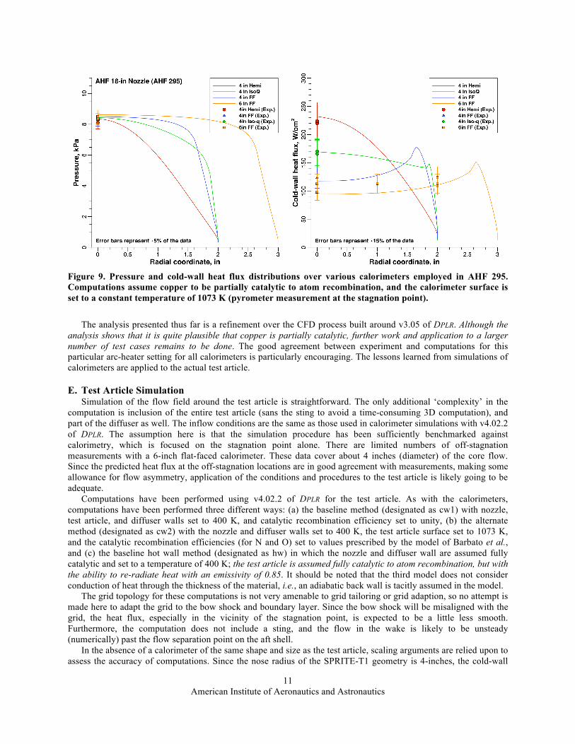
The agreement between computation and experiment at the stagnation point is now excellent for all calorimeters. The pressure and heat flux distributions for the 4 calorimeters – hemispherical, iso-q, and flat-face cylindrical – are shown in Fig. 9.
American Institute of Aeronautics and Astronautics
11
Figure 9. Pressure and cold-wall heat flux distributions over various calorimeters employed in AHF 295. Computations assume copper to be partially catalytic to atom recombination, and the calorimeter surface is set to a constant temperature of 1073 K (pyrometer measurement at the stagnation point).
The analysis presented thus far is a refinement over the CFD process built around v3.05 of DPLR. Although the
analysis shows that it is quite plausible that copper is partially catalytic, further work and application to a larger number of test cases remains to be done. The good agreement between experiment and computations for this particular arc-heater setting for all calorimeters is particularly encouraging. The lessons learned from simulations of calorimeters are applied to the actual test article.
E. Test Article Simulation Simulation of the flow field around the test article is straightforward. The only additional ‘complexity’ in the
computation is inclusion of the entire test article (sans the sting to avoid a time-consuming 3D computation), and part of the diffuser as well. The inflow conditions are the same as those used in calorimeter simulations with v4.02.2 of DPLR. The assumption here is that the simulation procedure has been sufficiently benchmarked against calorimetry, which is focused on the stagnation point alone. There are limited numbers of off-stagnation measurements with a 6-inch flat-faced calorimeter. These data cover about 4 inches (diameter) of the core flow. Since the predicted heat flux at the off-stagnation locations are in good agreement with measurements, making some allowance for flow asymmetry, application of the conditions and procedures to the test article is likely going to be adequate.
Computations have been performed using v4.02.2 of DPLR for the test article. As with the calorimeters, computations have been performed three different ways: (a) the baseline method (designated as cw1) with nozzle, test article, and diffuser walls set to 400 K, and catalytic recombination efficiency set to unity, (b) the alternate method (designated as cw2) with the nozzle and diffuser walls set to 400 K, the test article surface set to 1073 K, and the catalytic recombination efficiencies (for N and O) set to values prescribed by the model of Barbato et al., and (c) the baseline hot wall method (designated as hw) in which the nozzle and diffuser wall are assumed fully catalytic and set to a temperature of 400 K; the test article is assumed fully catalytic to atom recombination, but with the ability to re-radiate heat with an emissivity of 0.85. It should be noted that the third model does not consider conduction of heat through the thickness of the material, i.e., an adiabatic back wall is tacitly assumed in the model.
The grid topology for these computations is not very amenable to grid tailoring or grid adaption, so no attempt is made here to adapt the grid to the bow shock and boundary layer. Since the bow shock will be misaligned with the grid, the heat flux, especially in the vicinity of the stagnation point, is expected to be a little less smooth. Furthermore, the computation does not include a sting, and the flow in the wake is likely to be unsteady (numerically) past the flow separation point on the aft shell.
In the absence of a calorimeter of the same shape and size as the test article, scaling arguments are relied upon to assess the accuracy of computations. Since the nose radius of the SPRITE-T1 geometry is 4-inches, the cold-wall

American Institute of Aeronautics and Astronautics
12
heat flux should be roughly 41% lower than that for the hemisphere based on the Fay-Riddell correlation. From Table 2, this works out to roughly 155-160 W/cm2 – the upper estimate coming from the fact that the nose radius of the SPRITE-T1 geometry and that of the 4-inch iso-q calorimeter are very similar (3.57 vs 4.00 inches).
Distributions of surface pressure and heat flux obtained from the three computations mentioned above are shown in Fig. 10. Also shown are the predicted surface shear stresses and temperatures in Fig. 11.
(a) Surface pressure (b) Surface heat flux
Figure 10. Pressure and heat flux (cold and hot wall) distributions over the SPRITE-T1 configuration tested in AHF 295. Results of computations in which all walls (nozzle, test article, and diffuser) are set to 400 K are designated by ‘cw1’ (blue curves) and computations in which the test article surface temperature is set to 1073 K, and the nozzle and diffuser walls set to 400 K are designated by ‘cw2’ (green curves). The hot-wall computations are designated by ‘hw’ (red curves).
(a) Surface shear (magnitude) (b) Surface temperature (adiabatic back wall)
Figure 11. Shear stress and temperature distributions over the SPRITE-T1 configuration tested in AHF 295. Results of computations in which all walls (nozzle, test article, and diffuser) are set to 400 K (127 °C) are designated by ‘cw1’ (blue curves) and computations in which the test article surface temperature is set to 1073 K (800 °C), and the nozzle and diffuser walls set to 400 K (127 °C) are designated by ‘cw2’ (green curves). The hot-wall computations are designated by ‘hw’ (red curves).
The predicted radiation equilibrium temperatures (albeit with an adiabatic back wall) in the hot-wall
computations are in excess of 2000 °C. At such temperatures, the assumption of a fully catalytic wall is tenuous. However, it is assumed that the heat transfer coefficient, required in materials thermal response computations, is

American Institute of Aeronautics and Astronautics
13
weakly dependent on wall temperature. Therefore, the results of the hot-wall computations for the SPRITE-T1 configuration are used in response computations.
F. Materials Thermal Response Analysis The computed flow field solution for the hot-wall case was post-processed using an in-house software utility,
BLAYER,20 to extract boundary-layer properties – edge, wall, thickness, etc. The surface pressure, edge enthalpy, and convective heat transfer coefficient (film coefficient) were extracted at locations corresponding to the center of each instrumented plug (see Fig. 1). These quantities were provided as inputs to v2.6.1 of the materials thermal response code, FIAT. The stack-up of the material on the heatshield was defined as PICA with 0.01 inch thick RTV-560 to bond the material to 0.125 thick Al-2024 (the structural shell). While the thickness of PICA is 1 inch over the conical frustum, it is about 1.36 inches thick at the stagnation point, because the aluminum shell had a flat face rather than a curved one conforming to the nose radius of the OML. Each instrumented plug had 3 in-depth K-type thermocouples. The 2 plugs on the conical frustum had the thermocouples at nominal depths of 0.125, 0.375, and 0.625 inch, and for the stagnation point plug these depths were 0.25, 0.50, and 0.75 inch. The inputs used in FIAT computations are shown in Table 3. Computations were run out to 3600 seconds, which included 50 seconds of exposure of the test article to the arc-heated stream.
Table 3. Inputs to FIAT v2.6.1
Plug location PICA
thickness TTT fiber orientation H ρ eueCH p
in BTU/lbm lbm/ft2.s atm Stagnation point 1.36 0° 5869 0.0310 0.0828 Mid-cone 1.00 45° 5877 0.0126 0.0379 Bottom cone 1.00 45° 5878 0.0104 0.0377
Predicted time histories of surface temperature and thermocouple temperatures are shown in Fig. 12 through Fig.
14, respectively for the three instrumented plugs at the apex, mid-frustum, and end-frustum regions of the test article. In these figures, FIAT predictions are shown as red lines, and measurements (pyrometer or thermocouple data) are shown as black lines.
(a) Surface temperature (b) In-depth temperature
Figure 12. Time histories of (a) FIAT predicted surface temperatures (red lines) and measured surface temperatures (black lines), and (b) FIAT predicted temperatures in the material at 3 depths from the surface and thermocouple measurements. Results are shown for the instrumented plug at the apex (spherical nose cap) of the model (see Fig. 1).

American Institute of Aeronautics and Astronautics
14
(a) Surface temperature (b) In-depth temperature
Figure 13. Time histories of (a) FIAT predicted surface temperatures (red lines) and measured surface temperatures (black lines), and (b) FIAT predicted temperatures in the material at 3 depths from the surface and thermocouple measurements. Results are shown for the instrumented plug at the middle of the conical frustum (see Fig. 1).
(a) Surface temperature (b) In-depth temperature
Figure 14. Time histories of: (a) FIAT predicted surface temperatures (red lines) and measured surface temperatures (black lines), and (b) FIAT predicted temperatures in the material at 3 depths from the surface and thermocouple measurements. Results are shown for the instrumented plug at the end of the conical frustum (see Fig. 1).
The surface temperature trends appear to match well against predictions (Figs. 15a, 16a, and 17a), as do the
trends at the in-depth thermocouple locations. At a time instant of t = 25 s (mid-point of the 50 s exposure time for the test article), values of temperature measured using pyrometers are compared with predicted surface temperatures in Table 4. Predictions are always above the measurements by as much as 80 °C. Whether these differences are due to higher inflow enthalpy has not yet been explored fully. Further, for the instrumented plug at the center of the
American Institute of Aeronautics and Astronautics
15
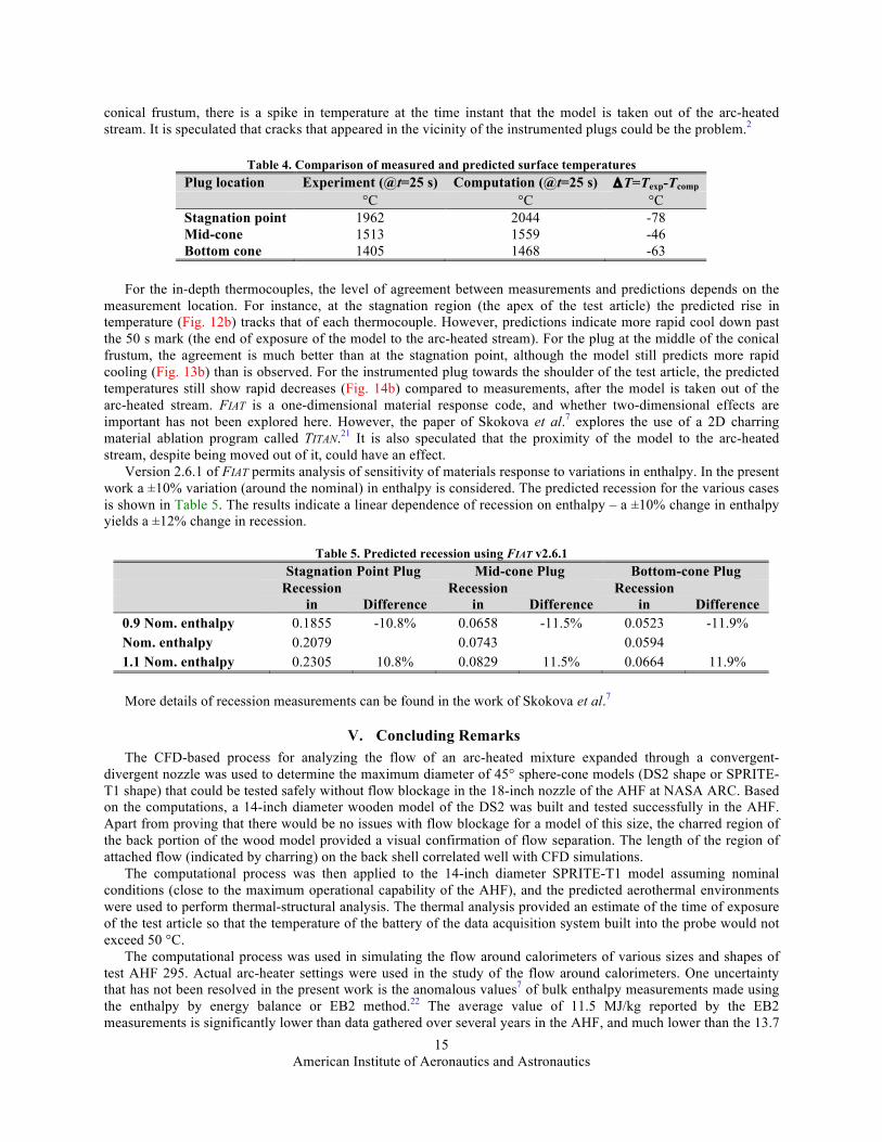
conical frustum, there is a spike in temperature at the time instant that the model is taken out of the arc-heated stream. It is speculated that cracks that appeared in the vicinity of the instrumented plugs could be the problem.2
Table 4. Comparison of measured and predicted surface temperatures
Plug location Experiment (@t=25 s) Computation (@t=25 s) ΔT=Texp-Tcomp °C °C °C Stagnation point 1962 2044 -78 Mid-cone 1513 1559 -46 Bottom cone 1405 1468 -63
For the in-depth thermocouples, the level of agreement between measurements and predictions depends on the
measurement location. For instance, at the stagnation region (the apex of the test article) the predicted rise in temperature (Fig. 12b) tracks that of each thermocouple. However, predictions indicate more rapid cool down past the 50 s mark (the end of exposure of the model to the arc-heated stream). For the plug at the middle of the conical frustum, the agreement is much better than at the stagnation point, although the model still predicts more rapid cooling (Fig. 13b) than is observed. For the instrumented plug towards the shoulder of the test article, the predicted temperatures still show rapid decreases (Fig. 14b) compared to measurements, after the model is taken out of the arc-heated stream. FIAT is a one-dimensional material response code, and whether two-dimensional effects are important has not been explored here. However, the paper of Skokova et al.7 explores the use of a 2D charring material ablation program called TITAN.21 It is also speculated that the proximity of the model to the arc-heated stream, despite being moved out of it, could have an effect.
Version 2.6.1 of FIAT permits analysis of sensitivity of materials response to variations in enthalpy. In the present work a ±10% variation (around the nominal) in enthalpy is considered. The predicted recession for the various cases is shown in Table 5. The results indicate a linear dependence of recession on enthalpy – a ±10% change in enthalpy yields a ±12% change in recession.
Table 5. Predicted recession using FIAT v2.6.1
Stagnation Point Plug Mid-cone Plug Bottom-cone Plug Recession Recession Recession
in Difference in Difference in Difference 0.9 Nom. enthalpy 0.1855 -10.8% 0.0658 -11.5% 0.0523 -11.9% Nom. enthalpy 0.2079 0.0743 0.0594 1.1 Nom. enthalpy 0.2305 10.8% 0.0829 11.5% 0.0664 11.9%
More details of recession measurements can be found in the work of Skokova et al.7
V. Concluding Remarks The CFD-based process for analyzing the flow of an arc-heated mixture expanded through a convergent-
divergent nozzle was used to determine the maximum diameter of 45° sphere-cone models (DS2 shape or SPRITE-T1 shape) that could be tested safely without flow blockage in the 18-inch nozzle of the AHF at NASA ARC. Based on the computations, a 14-inch diameter wooden model of the DS2 was built and tested successfully in the AHF. Apart from proving that there would be no issues with flow blockage for a model of this size, the charred region of the back portion of the wood model provided a visual confirmation of flow separation. The length of the region of attached flow (indicated by charring) on the back shell correlated well with CFD simulations.
The computational process was then applied to the 14-inch diameter SPRITE-T1 model assuming nominal conditions (close to the maximum operational capability of the AHF), and the predicted aerothermal environments were used to perform thermal-structural analysis. The thermal analysis provided an estimate of the time of exposure of the test article so that the temperature of the battery of the data acquisition system built into the probe would not exceed 50 °C.
The computational process was used in simulating the flow around calorimeters of various sizes and shapes of test AHF 295. Actual arc-heater settings were used in the study of the flow around calorimeters. One uncertainty that has not been resolved in the present work is the anomalous values7 of bulk enthalpy measurements made using the enthalpy by energy balance or EB2 method.22 The average value of 11.5 MJ/kg reported by the EB2 measurements is significantly lower than data gathered over several years in the AHF, and much lower than the 13.7

American Institute of Aeronautics and Astronautics
16
MJ/kg estimate for the enthalpy on the nozzle centerline. This difference suggests that the inflow to the convergent-divergent nozzle is non-uniform, a finding that is not borne out by a combination of heat flux-pitot sweeps of the free jet. This discrepancy in EB2 measurements was ignored in the present work, and computations performed assuming a uniform inflow with a bulk enthalpy of 13.7 MJ/kg.
The computational process, developed around v3.05 of DPLR, was upgraded to one based on v4.02.2. This upgrade utilizes the new capability of DPLR to handle subsonic inflows with a characteristics based method, thus eliminating the need to specify an inflow Mach number (as in the older framework). However, it should be noted that this gain is currently limited to uniform inflow conditions, and DPLR will require further modifications to handle pointwise specification of inflow mass flow and enthalpy. The resulting predictions were found not to have as much internal consistency as the measurements, and it was hypothesized that the copper slugs used in the calorimeters were partially catalytic to atom (N and O) recombination at the surface. Using a model of copper catalycity developed by Barbato et al. flow simulations were performed again, and this time the predicted results were not only in good agreement with measurements across all shape/size calorimeters used in the test. Despite its success, the hypothesis of partial catalycity remains to be tested across several operating conditions of both the AHF and IHF before any definitive conclusions can be made.
Next, the CFD-based process was applied to the actual test article, SPRITE-T1, assuming the entire model (including the aft shell) to be fully catalytic to atom recombination. The predicted aerothermal environments (notable pressure and heat flux) were used in the material thermal response code, FIAT. The results of FIAT predictions were compared against surface temperature measurements made with optical pyrometers, and with temperature traces of in-depth thermocouples placed in the forebody TPS material, PICA. The comparisons were found to be fair for surface temperatures. For in-depth temperatures, while the temperature rise was well predicted for all thermocouples for the exposure period of 50 s, FIAT predicted a more rapid cool down than measurements. Whether this has something to do with material cracking (observed after taking the model out of the arc-heated stream), or with two-dimensional heat conductions effects, or even proximity to the heated stream after the model has been taken out, still remains to be investigated. Having a calorimeter of the same size and shape as the SPRITE-T1 test article would have also helped in determining whether there were flow non-uniformities in the test.
Acknowledgments The author was supported by Contract NNA10DE12C to ERC, Inc. from the Entry Systems and Technology
Division at NASA Ames Research Center. Helpful discussions with the SPRITE team – Daniel Empey, Kristina Skokova, Parul Agrawal, Greg Swanson, Keith Peterson, Ethiraj Venkatapathy – were critical to the success of this modest in-house project. The support of the arc-jet crew and test engineers, especially Imelda Terrazas-Salinas, is gratefully acknowledged. Critical financial support was provided by NASA-SCAP for the arc-jet operational capability at NASA Ames Research Center.
References 1Venkatapathy, E., Prabhu, D., Skokova, K, Peterson, K., Agrawal, P., Swanson, G., and Empey, D., “Overview of Recent
Advancements in Small Probe Reentry Investigation for TPS Engineering (SPRITE),” 50th AIAA Aerospace Sciences Meeting, Nashville, TN, January 2012.
2Empey, D. M., Skokova, K. S., Agrawal, P., Swanson, G. T., Prabhu, D. K., Peterson, K. H., Winter, M., and Venkatapathy, E., “Small Probe Reentry Investigation for TPS Engineering (SPRITE),” 50th AIAA Aerospace Sciences Meeting, Nashville, TN, January 2012.
3Howard, A. R., Prabhu, D. K., Venkatapathy, E., and Arnold, J. O., “Small Probes as Flight Test Beds for Thermal Protection Materials,” Proceedings of the 7th International Planetary Probe Workshop, Barcelona, Spain, 2010.
4Spenser, D., “Results and analysis of large scale article testing in the Ames 60 MW interaction heating arc jet facility,” 50th AIAA Aerospace Sciences Meeting, Nashville, TN, January 2012.
5Loomis, M. P., Prabhu, D. K., Gorbunov, S., Olson, M., and Vander Kam, J., “Results and analysis of large scale article testing in the Ames 60 MW interaction heating arc jet facility,” AIAA Paper 2010-445, 48th AIAA Aerospace Sciences Meeting, Orlando, FL, January 2010.
6Mitcheltree, R. A., DiFulvio, M., Horvath, T. J., and Braun, R. D., “Aerothermal Heating Predictions for Mars Microprobe,” Journal of Spacecraft and Rockets, Vol. 36, No. 3, May-June 1999.
7Skokova, K., Prabhu, D. K., and Chen, Y.-K., “Arc Jet Testing of a Small Entry Probe (SPRITE),” 50th AIAA Aerospace Sciences Meeting, Nashville, TN, January 2012.
8Oishi, Tomo, Martinez, Edward, R. and Santos, Jose, A. “Development and Application of a TPS Ablation Sensor for Flight”, 46th AIAA Aerospace Sciences Meeting and Exhibit Paper AIAA 2008-1219, Reno, NV, January 2008.
9Gazarik, M. J., Hwang, H., Little, A., Cheatwood, N., Wright, M., and Herath, J., “Overview of the MEDLI Project,” Proceedings of the 5th International Planetary Probe Workshop, Bordeaux, France, June 2007.

American Institute of Aeronautics and Astronautics
17
10Swanson, G. T., Empey, D. M., Skokova, K. A., and Venkatapathy, E., “Development of an Integrated Data Acquisition System for a Small Flight Probe,” 50th AIAA Aerospace Sciences Meeting, Nashville, TN, January 2012.
11Agrawal, P., Chen, Y.-K., and Prabhu, D.K., “Thermal soak analysis of SPRITE probe,” 50th AIAA Aerospace Sciences Meeting, Nashville, TN, January 2012.
12Wright, M. J.,White, T. and Mangini, N., “Data-Parallel Line Relaxation Methods (DPLR) Code User Manual Acadia-Version 4.01.1,” NASA/TM-2009-215388, October 2009.
13Chen, Y.-K., and Milos, F. S., “Ablation and Thermal Response Program for Spacecraft Heatshield Analysis,” Journal Spacecraft and Rockets, Vol. 36, No. 3, 1999, pp. 475-483.
14MSC Software Corporation, 2 MacArthur Place, Santa Ana, CA 92707. 15Prabhu, D. K., Saunders, D., Oishi, T., Skokova, K., Santos, J., Fu, J., Terrazas-Salinas, I., Carballo, E., and Driver, D.,
“CFD Analysis Framework for Arc-Heated Flowfields, I: Stagnation Testing in Arc-jets at NASA ARC,” AIAA Paper AIAA-2009-4080, June 2009.
16Saunders, D. and Gökçen, T., “Nozzle Throat Conditions for Arc-jet Computations (1) Axisymmetric,” ELORET Report TSA-01-DB2-1-2008, October 2008.
17Gordon, S., and McBride, B. J., “Computer program for calculations of complex chemical equilibrium compositions, rocket performance, incident and reflected shock, and Chapman-Jouguet detonations,” NASA/SP-273, 1976.
18Davies, C. B., and Venkatapathy, E., “SAGE: The Self-Adaptive Grid CodE,” NASA/TM-1999-208792, August 1999. 19Barbato, M., Reggiani, S., Bruno, C., and Muylaert, J., “Model for Heterogeneous Catalysis on Metal Surfaces with
Applications to Hypersonic Flows,” Journal of Thermophysics and Heat Transfer, Vol. 14, No. 3, 2000, pp. 412-420. 20BLAYER is an in-house software utility developed by David Saunders for calculating boundary-layer properties from
flowfield solutions at NASA ARC. 21Chen, Y.-K. and Milos, F. S., “Two-Dimensional Implicit Thermal Response and Ablation Program for Charring
Materials,” Journal of Spacecraft and Rockets, Vol. 38, No. 4, July-August 2001. 22Hightower, T. M., Balboni, J. A., MacDonald, C. L., Anderson, K. F., and Martinez, E. R., “Enthalpy by Energy Balance
for Aerodynamic Heating Facility at NASA Ames Research Center Arc Jet Complex," 48th International Instrumentation Symposium, The Instrumentation Systems, and Automation Society, Research Triangle Park, NC, May 2002.