Flow Visualization Tunnel - Virginia Techaborgolt/aoe3054/manual/expt1/AerolabFVT... · AEROLAB...
15
©AEROLAB LLC 2009 Flow Visualization Tunnel Owner’s Manual May 2009
Transcript of Flow Visualization Tunnel - Virginia Techaborgolt/aoe3054/manual/expt1/AerolabFVT... · AEROLAB...

©AEROLAB LLC 2009
Flow Visualization Tunnel
Owner’s Manual
May 2009

AEROLAB Flow Visualization Tunnel Owner’s Manual
www.aerolab.com 2 301-776-6585
Contents
Introduction ..................................................................................................... 3
Description ....................................................................................................... 3
Warnings / Precautions ...................................................................................... 4
Tunnel Overview ............................................................................................... 5
Main Control Panel ............................................................................................ 6
Basic Operation ................................................................................................ 8
Auxiliary Blower and Throttle Valve Operation ...................................................... 9
Delta and Rectangular Wing Model Installation .................................................. 10
Airfoil and Venturi Model Installation ................................................................. 11
Spin Model Installation .................................................................................... 12
Model Operation and Experiment Suggestions .................................................... 13
Airfoil w/ Blown Flap .................................................................................... 13
Airfoil w/ Vacuum Holes ................................................................................ 13
Airfoil for Student Experimentation ................................................................ 14
Airfoil w/ Tangential Blowing Slots ................................................................. 14
Venturi ....................................................................................................... 14
Circular Cylinder (Spin Model) ....................................................................... 15
Delta Wing .................................................................................................. 15
Rectangular Wing ........................................................................................ 15

AEROLAB Flow Visualization Tunnel Owner’s Manual
www.aerolab.com 3 301-776-6585
Introduction
The shape of an object moving through a fluid has a major influence on the way the fluid reacts. Using the AEROLAB Flow Visualization Tunnel (FVT), students can see firsthand the flow of air over objects such as airfoils, wings, cylinders and other aerodynamic shapes.
While the AEROLAB Flow Visualization Tunnel is great for group demonstrations, it’s also intended for hands-on student experimentation. Students can change pitch angles, deflect flaps, rotate circular cylinders and apply vacuum or blowing to improve aerodynamic performance. Hands-on activities motivate learners because the effects of their adjustments are immediate and obvious.
Description
wind tunnel - Length: 53 inches (1.35m) Height: 28.5 inches (72cm) Width: 17 inches (43cm)
cabinet - Height: 37 inches (94cm) Width: 45.5 inches (1.16m) Depth: 24 inches (61cm) Power requirements: 115 VAC, 60 Hz, minimum 15 Amp circuit, international use
requires a transformer
Flow visualization tunnels, in particular, require exceptionally smooth, steady airflow. This quality of airflow is aerodynamically termed laminar flow. Laminar flow contains no eddies or other types of turbulence. Turbulence is undesirable because it diffuses the injected water vapor lines causing them to lose definition and appear fuzzy.
In general, laminar flow is not easy to generate and difficult to maintain. Two factors promote laminar flow: a carefully designed inlet bell mouth (known as the contraction) and an effective honeycomb flow straightener. The AEROLAB Flow Visualization Tunnel design includes a large-area-ratio (inlet to outlet) contraction and engineered aluminum honeycomb. The honeycomb provides approximately 7700 hexagonal channels, 7 inches in length and 1/8 inch across flats (Aspect Ratio 56). Honeycomb is also employed at the exit of the model area to ensure laminar flow.
Vaporized water (created by an ultrasonic atomizer) is introduced in streaklines spaced 0.25 inches (6.35mm) apart through a special rake. The rake is located near the exit of
AEROLAB Flow Visualization Tunnel Owner’s Manual
www.aerolab.com 4 301-776-6585
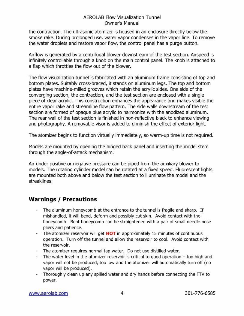
the contraction. The ultrasonic atomizer is housed in an enclosure directly below the smoke rake. During prolonged use, water vapor condenses in the vapor line. To remove the water droplets and restore vapor flow, the control panel has a purge button.
Airflow is generated by a centrifugal blower downstream of the test section. Airspeed is infinitely controllable through a knob on the main control panel. The knob is attached to a flap which throttles the flow out of the blower.
The flow visualization tunnel is fabricated with an aluminum frame consisting of top and bottom plates. Suitably cross-braced, it stands on aluminum legs. The top and bottom plates have machine-milled grooves which retain the acrylic sides. One side of the converging section, the contraction, and the test section are enclosed with a single piece of clear acrylic. This construction enhances the appearance and makes visible the entire vapor rake and streamline flow pattern. The side walls downstream of the test section are formed of opaque blue acrylic to harmonize with the anodized aluminum. The rear wall of the test section is finished in non-reflective black to enhance viewing and photography. A removable visor is added to diminish the effect of exterior light.
The atomizer begins to function virtually immediately, so warm-up time is not required.
Models are mounted by opening the hinged back panel and inserting the model stem through the angle-of-attack mechanism.
Air under positive or negative pressure can be piped from the auxiliary blower to models. The rotating cylinder model can be rotated at a fixed speed. Fluorescent lights are mounted both above and below the test section to illuminate the model and the streaklines.
Warnings / Precautions
- The aluminum honeycomb at the entrance to the tunnel is fragile and sharp. If
mishandled, it will bend, deform and possibly cut skin. Avoid contact with the
honeycomb. Bent honeycomb can be straightened with a pair of small needle nose
pliers and patience.
- The atomizer reservoir will get HOT in approximately 15 minutes of continuous
operation. Turn off the tunnel and allow the reservoir to cool. Avoid contact with
the reservoir.
- The atomizer requires normal tap water. Do not use distilled water.
- The water level in the atomizer reservoir is critical to good operation – too high and
vapor will not be produced, too low and the atomizer will automatically turn off (no
vapor will be produced).
- Thoroughly clean up any spilled water and dry hands before connecting the FTV to
power.
AEROLAB Flow Visualization Tunnel Owner’s Manual
www.aerolab.com 5 301-776-6585
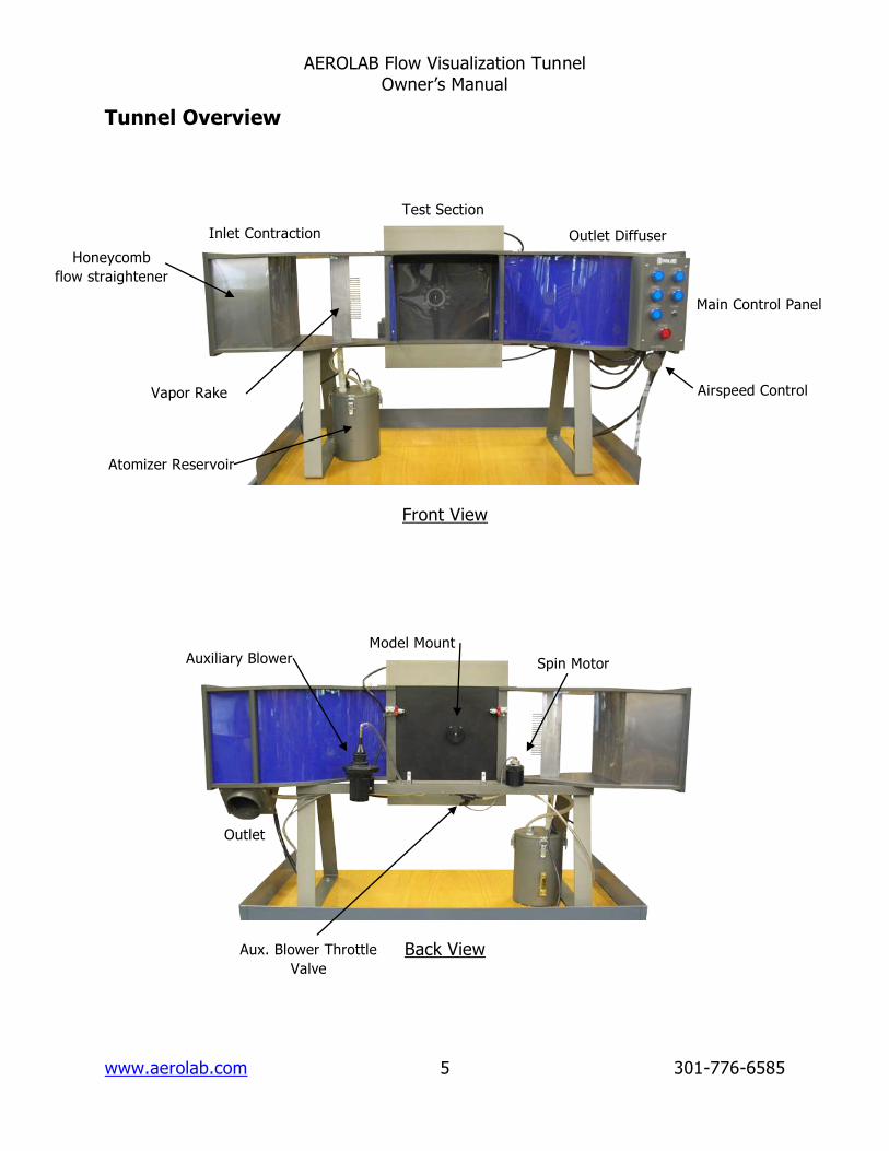
Tunnel Overview
Front View
Back View
Auxiliary Blower Spin Motor
Model Mount
Outlet
Aux. Blower Throttle
Valve
Inlet Contraction
Test Section
Outlet Diffuser
Main Control Panel
Airspeed Control Vapor Rake
Atomizer Reservoir
Honeycomb
flow straightener

AEROLAB Flow Visualization Tunnel Owner’s Manual
www.aerolab.com 6 301-776-6585
Main Control Panel
Main Control Panel
The POWER button is the main switch for the tunnel. Nothing can
operate unless this switch is engaged. The air compressor
(located inside the cabinet) will run for a short period of time
when this button is activated. The compressor is audible.
The FAN button activates the wind tunnel fan.
The SMOKE button activates the atomizer.

AEROLAB Flow Visualization Tunnel Owner’s Manual
www.aerolab.com 7 301-776-6585
The SPIN CYLINDER button activates the cylinder electric motor.
The VACUUM button activates the auxiliary blower. The blower
provides pressurized air and/or vacuum to the vacuum/blowing
models.
The PURGE button provides a short blast of air to the vapor rake.
This blast of air clears the rake of collected water droplets.
The LIGHTS button activates the lights located above the below
the test model.
The AIR SPEED knob changes the airspeed through the wind
tunnel. Turn the knob clockwise to slow the flow or
counterclockwise to speed it up.

AEROLAB Flow Visualization Tunnel Owner’s Manual
www.aerolab.com 8 301-776-6585
Basic Operation
WARNING – Never mix water and electricity. It can cause serious injury or death.
Never connect or disconnect the FVT to power with wet hands or spilled
water in the area.
1) With the FVT unplugged from power, check the reservoir
water level. A sight glass is located on the side of the
reservoir. If no water is needed, skip to step 3.
2) To fill the reservoir, lift the spring-
loaded reservoir cap and slip in the
supplied funnel. Add normal tap water
while watching the sight glass. Marks
on the sight glass indicate upper and
lower water levels. Remove the funnel.
3) Connect the FVT to power.
4) The main control panel (see page 6) is located on the front of the tunnel.
Press the power button to enable the tunnel.
5) Install / prepare the test
model (see page 10) and close
/ latch the back access door.
6) Press the FAN button to start airflow.
7) Press the SMOKE button. NOTE – the atomizer reservoir will get HOT in
approximately 15 minutes of continuous use. As such, turn off the atomizer
when it is not needed, for example, during a model change. If the reservoir
gets hot to the touch, it must be allowed to cool down or damage to the
atomizer could result. Water vapor streaklines will become visible in a few
seconds.
8) Press the LIGHTS button to activate the lights.
9) The AIR SPEED knob can be adjusted as preferred. Turn the knob clockwise
to slow down the airspeed or counterclockwise to speed up the airspeed.

AEROLAB Flow Visualization Tunnel Owner’s Manual
www.aerolab.com 9 301-776-6585
Note – The airspeed knob has an effect on water vapor density; at higher
speeds the water vapor will be thinner than at slower speeds.
10) From time to time, water droplets will collect in the vapor rake tubes.
Momentarily, press the PURGE button to blow the droplets free of the vapor
rake. This purging may need to be done two or three times for best results.
11) The FVT can be completely turned off with the POWER button. However, it
would be best to make certain the VACUUM and SPIN CYLINDER buttons are
off before using the POWER button to avoid potential damage to the motor
and auxiliary blower at restart.
Auxiliary Blower and Throttle Valve Operation
The auxiliary blower is located on the back side of the
FVT. It is activated by means of the VACUUM button on
the main control panel (see page 6). The blower is used
for both vacuum and blowing. The conical fitting is a
press-and-twist fit.
set for vacuum set for blowing
The throttle valve is located on the back frame member and is used to vary the
vacuum and blowing intensity to the airfoil models. It can easily be adjusted from

AEROLAB Flow Visualization Tunnel Owner’s Manual
www.aerolab.com 10 301-776-6585
the front of the FVT for precise settings. The valve is adjustable from fully-closed to
fully-open in 90° of travel.
Auxiliary Blower Throttle Valve
Delta and Rectangular Wing Model Installation
Note – Although the AEROLAB Flow Visualization Tunnel is designed to give
generations of service, care should be taken to avoid damage. Never force a
model into the holder. If it does not go into position easily, investigate the
situation before force is applied.
1) Identify the delta wing and flat plate model mounting
post (shown to the left).
2) Identify the airfoil and wing model mount (shown to the
left). Make certain it is installed in the back access door.
To do so, press the narrow end of the model mount into
the hole in the back access door. The mount has spring-
loaded pins used to hold it in place.
3) Unlatch the back access door and slide the post
through the model holder.

AEROLAB Flow Visualization Tunnel Owner’s Manual
www.aerolab.com 11 301-776-6585
4) While holding the post on the inside face of the back
access door, install the locking nut to finger-tightness.
5) Slide the delta or rectangular wing model onto the
mounting post.
6) Adjust the pitch angle as desired.
7) Turn the model mount in the back access door to align the model with the
flow (the yaw angle).
Airfoil and Venturi Model Installation
1) Unlatch and open the back access door.
2) Note the brass tube and alignment pin located on the
side of each model. Note the two holes on the model
holder. Slide the brass tube into the model holder
and align the pin. Slide the model onto holder until
the alignment pin engages with the pin hole.

AEROLAB Flow Visualization Tunnel Owner’s Manual
www.aerolab.com 12 301-776-6585
3) For blowing / vacuum models, hold the model in one
hand while pressing the auxiliary blower tube onto the
brass model tube. Note – The auxiliary blower tube
should be pressed on only SLIGHTLY. Otherwise,
removal will be difficult.
4) Close and latch the back access door.
Spin Model Installation
1) Remove the airfoil and wing model mount. To do so,
gently pull the mount back away from the tunnel
while rocking side to side.
2) Install the spin model holder into the back access
door as you would the airfoil and wing model mount.
It, too, has spring-loaded pins used to hold it in place.
3) Slide the cylinder model onto the square motor shaft.

AEROLAB Flow Visualization Tunnel Owner’s Manual
www.aerolab.com 13 301-776-6585
4) While holding the cylinder, thread the lock nut onto
the motor shaft. This will prevent the cylinder from
coming loose and scratching the tunnel window.
5) Close and latch the back access door.
Model Operation and Experiment Suggestions
Note - Because the airfoil models span the test area (they go from wall to wall), air
is forced to move in only two dimensions (it cannot flow sideways to go around the
ends of the models). This type of flow is termed two-dimensional.
Airfoil w/ Blown Flap
The Flap Model is intended to be used with and without
blowing – note the slot just in front of the flap hinge on
the top of the airfoil. The flap can be adjusted down or
up. The model demonstrates the Coanda Effect when
used with blowing. The Coanda Effect is used to
increase high angle-of-attack performance. The
intensity of the blowing should be adjusted to the
lowest possible setting to achieve the desired result.
The Boeing C-17 Globemaster III employs blown flaps
to increase performance.
Airfoil w/ Vacuum Holes
Vacuum applied to the top surface of a wing can
increase high angle-of-attack performance. The
Airfoil with Vacuum Holes serves to demonstrate this
phenomenon. The intensity of the vacuum should be
adjusted to the lowest possible setting to achieve the
desired result. As an added experiment, use
cellophane tape to partially or fully close holes and
observe the result.

AEROLAB Flow Visualization Tunnel Owner’s Manual
www.aerolab.com 14 301-776-6585
Airfoil for Student Experimentation
A large chamber has been cut into the top surface of
the student experimentation airfoil. The chamber can
be covered with tape or paper and holes or slots can
be opened to experiment with the application of
blowing or vacuum.
Airfoil w/ Tangential Blowing Slots
Similar to the Airfoil w/ Blown Flap, this model
employs blowing (the Coanda Effect) to increase
performance. Visible on the top surface, there are
two slots. These slots have been designed such that
the pressurized air is directed back and tangential
(parallel) to the upper surface. Operate the model
with and without blowing. Adjust the blowing
intensity to the lowest possible setting to achieve the
desired result. As an added experiment, use
cellophane tape to partially or fully close slots and
observe the result.
Venturi
The Venturi model serves to demonstrate the effect of a
converging duct on moving air. Observe the streaklines as they
pass through the model. Change the pitch angle of the model
and observe the streaklines.

AEROLAB Flow Visualization Tunnel Owner’s Manual
www.aerolab.com 15 301-776-6585
Circular Cylinder (Spin Model)
The Circular Cylinder serves to demonstrate the Magnus Effect.
Operate the tunnel with and without the cylinder spinning.
Note the direction of the spin and the effect on the streaklines.
By observing the vapor lines, what is happening and why?
Note – The direction of rotation
can be changed by switching the
leads on the motor power supply
located in the lower cabinet.
Note - The delta and rectangular wing models allow air to flow around them just as
it would on an actual aircraft. This is termed three-dimensional flow because the air
is allowed to move in all three dimensions.
Delta Wing
The delta wing model serves to demonstrate the
vortices generated by such a wing design. The
wing’s angle of attack can be adjusted by gently
twisting the wing on the mounting post. Also,
change the yaw, or side-slip, angle of the model by
means of the model mount and observe the result.
Discuss the advantages of a delta-wing aircraft.
What is the benefit of the obvious vortices
generated on the top of the wing?
Rectangular Wing
The rectangular wing model serves to demonstrate
the vortices generated by such a wing design. The
wing’s angle of attack can be adjusted by gently
twisting the wing on the mounting post. Discuss the
vortices – How do they affect the performance of the
wing?