
0 Versioning Panel John Turner Campbell Pryde Maciej Piechocki …. And YOU!
212-9-10
2
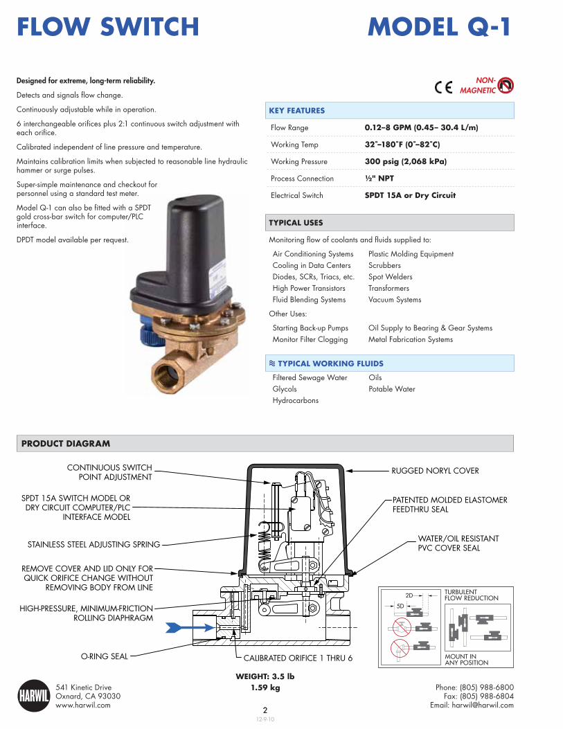
TURBULENT FLOW REDUCTION
MOUNT IN ANY POSITION
2D
5D
Phone: (805) 988-6800Fax: (805) 988-6804
Email: [email protected]
541 Kinetic DriveOxnard, CA 93030www.harwil.com
HARWIL®
Flow Switch
CONTINUOUS SWITCHPOINT ADJUSTMENT
STAINLESS STEEL ADJUSTING SPRING
REMOVE COVER AND LID ONLY FORQUICK ORIFICE CHANGE WITHOUT
REMOVING BODY FROM LINE
O-RING SEAL CALIBRATED ORIFICE 1 THRU 6
HIGH-PRESSURE, MINIMUM-FRICTIONROLLING DIAPHRAGM
PATENTED MOLDED ELASTOMERFEEDTHRU SEAL
WATER/OIL RESISTANTPVC COVER SEAL
RUGGED NORYL COVER
SPDT 15A SWITCH MODEL ORDRY CIRCUIT COMPUTER/PLC
INTERFACE MODEL
Model Q-1
weight: 3.5 lb1.59 kg
Product diagraM
tyPical uSeS
Monitoring flow of coolants and fluids supplied to:
Air Conditioning Systems Plastic Molding Equipment Cooling in Data Centers ScrubbersDiodes, SCRs, Triacs, etc. Spot WeldersHigh Power Transistors Transformers Fluid Blending Systems Vacuum Systems
Other Uses:
Starting Back-up Pumps Oil Supply to Bearing & Gear SystemsMonitor Filter Clogging Metal Fabrication Systems
tyPical working FluidS
Filtered Sewage Water OilsGlycols Potable WaterHydrocarbons
key FeatureS
Flow Range 0.12–8 gPM (0.45– 30.4 l/m)
Working Temp 32˚–180˚F (0˚–82˚C)
Working Pressure 300 psig (2,068 kPa)
Process Connection ½" nPt
Electrical Switch SPdt 15a or dry circuit
Designed for extreme, long-term reliability.
Detects and signals flow change.
Continuously adjustable while in operation.
6 interchangeable orifices plus 2:1 continuous switch adjustment with each orifice.
Calibrated independent of line pressure and temperature.
Maintains calibration limits when subjected to reasonable line hydraulic hammer or surge pulses.
Super-simple maintenance and checkout for personnel using a standard test meter.
Model Q-1 can also be fitted with a SPDT gold cross-bar switch for computer/PLC interface.
DPDT model available per request.
NoN-MagNetic

312-9-10
3
• Installation drawing and a numbered parts list is supplied with each unit.
• Special one-day delivery is available.
technical SPeciFicationS
Model Q-1
inStallation diMenSionS
toP View Side ViewFront View
ELECTRICAL CABLE FITTINGPER OPTION 1 OR 2
hyStereSiS (∆ Flow rate to actiVate/deactiVate Switch)≈ 5% at upper end of flow range≈ 25% at lower end of flow range
diFFerential PreSSure droPS acroSS unitUnder normal operating conditions:
≈ 1.0 psig at upper end of flow range≈ 5.0 psig at lower end of flow range
wetted MaterialSBody: Red brassHardware: Noryl (PPO) (10% glass fibers), 316 stainless steel, PlasticWorking fluid “sees” red brass,
316 stainless steel, phosphor bronze, and EPDM elastomer sealGasket: Cork/Nitrile blend Optional Seal: Hypalon, Viton
electrical Switch characteriSticSSPDT15A, ½ hp @ 125 or 250VAC½A @ 125VDC, ¼A @ 250VDC5A @ 125VAC (tungsten lamp load)
10,000,000 operations, median(Switch may be overloaded to 20A @ 125 or 250VAC for a minimum of 20,000 operations.)
working line PreSSure300 psi max.
working teMPerature180˚F max.(250˚F model available)
Model Selection chart
Flow Range (Water calibrated at 70˚F / 21˚C)
oriFice # continuouS Switch Point adjuStMent range
1 0.12 to 0.25 GPM
2 0.25 to 0.50 GPM
3 0.50 to 1 GPM
4 1 to 2 GPM
5 2 to 4 GPM
6 4 to 8 GPM
Note: Maximum recommended flow rate for each orifice is four (4) times the upper-end of the adjustment range.
electrical connection
groMMet cable o.d. diagraM
A 0.25”O.D.
AA 0.30”
B 0.37”
C 0.50”
conduit FittingS
F 0.5” straight F90˚ 0.5” 90˚
oPtion 1: Q-1 / 3 / a
BASE MODEL ↑ ↑ORIFICE
GROMMET SIzE
oPtion 2: Q-1 / 6 / F
BASE MODEL ↑ ↑ORIFICE
½" FLExIBLE CONDUIT FITTING
SaMPle Part nuMberS