
FLOW STRUCTURE of SUPERSONIC JETS from …munday/pubs/SERDP_Fluids09_UCp… · · 2009-06-25FLOW...
21
1 ver 1.05 FLOW STRUCTURE of SUPERSONIC JETS from CONICAL C-D NOZZLES David Munday * and Ephraim Gutmark † , University of Cincinnati Junhui Liu ‡ and K. Kailasanath § , Naval Research Laboratory This paper examines the flow structures emanating from convergent-divergent nozzles with conical sections like those used in practical high-speed propulsion applications. LES simulations and experimental measurements in the form of PIV and shadowgraph imaging and far-field acoustic measurement are employed. The development of the supersonic jets from these nozzles are examined in underexpanded, perfectly expanded and overexpanded conditions. It is found that in addition to the shock diamond features expected of smoothly contoured nozzles at off-design conditions, these nozzles produce a second set of shock diamonds anchored at the nozzle throat and overlaid on the shock diamonds shed from the nozzle lip. These together form a double- diamond appearance. These nozzles do not exhibit any shock-free condition at or near the expected design condition. As a consequence, there is no absence of shock noise at or near the design condition. Near the design condition there is a diminution in the intensity of the screech tone, but no diminution in the broad-band shock-associated noise. These nozzles produce shock cells 9%-25% shorter than cells from a comparable smoothly contoured nozzle. Nomenclature a speed of sound A e Nozzle exit area A* Nozzle throat area CFD Computational Fluid Dynamics D t Throat diameter D e Exit diameter M D Design Mach number M J Fully-expanded jet Mach number NPR Nozzle Pressure Ratio SPL Sound Pressure Level OASPL Over-All Sound Pressure Level ψ Inlet angle, measured from the upstream direction * Graduate Student; member AIAA. [email protected] † Distinguished Professor; Fellow AIAA. [email protected] ‡ Mechanical Engineer; member AIAA. [email protected] § Head, Center for Reactive Flow and Dynamical Systems; Fellow AIAA. [email protected]
Transcript of FLOW STRUCTURE of SUPERSONIC JETS from …munday/pubs/SERDP_Fluids09_UCp… · · 2009-06-25FLOW...

1 ver 1.05
FLOW STRUCTURE of SUPERSONIC JETS from CONICAL C-D NOZZLES
David Munday*and Ephraim Gutmark†,
University of Cincinnati
Junhui Liu‡and K. Kailasanath§, Naval Research Laboratory
This paper examines the flow structures emanating from convergent-divergent nozzles with conical sections like those used in practical high-speed propulsion applications. LES simulations and experimental measurements in the form of PIV and shadowgraph imaging and far-field acoustic measurement are employed. The development of the supersonic jets from these nozzles are examined in underexpanded, perfectly expanded and overexpanded conditions. It is found that in addition to the shock diamond features expected of smoothly contoured nozzles at off-design conditions, these nozzles produce a second set of shock diamonds anchored at the nozzle throat and overlaid on the shock diamonds shed from the nozzle lip. These together form a double-diamond appearance. These nozzles do not exhibit any shock-free condition at or near the expected design condition. As a consequence, there is no absence of shock noise at or near the design condition. Near the design condition there is a diminution in the intensity of the screech tone, but no diminution in the broad-band shock-associated noise. These nozzles produce shock cells 9%-25% shorter than cells from a comparable smoothly contoured nozzle.
Nomenclature a speed of sound Ae Nozzle exit area A* Nozzle throat area CFD Computational Fluid Dynamics Dt Throat diameter De Exit diameter MD Design Mach number MJ Fully-expanded jet Mach number NPR Nozzle Pressure Ratio SPL Sound Pressure Level OASPL Over-All Sound Pressure Level ψ Inlet angle, measured from the upstream direction * Graduate Student; member AIAA. [email protected] † Distinguished Professor; Fellow AIAA. [email protected] ‡ Mechanical Engineer; member AIAA. [email protected] § Head, Center for Reactive Flow and Dynamical Systems; Fellow AIAA. [email protected]

2 ver 1.05
Introduction Since the early twentieth century it has been recognized that convergent-divergent nozzles when operated off-design generate semi-periodic shock diamonds, as shocks and Prandtl-Meyer fans alternate in the jet plume [1]. For well-designed smoothly-contoured C-D nozzles with parallel exit flows it is expected that by matching the nozzle pressure ratio to the design nozzle pressure ratio the exit pressure will match the ambient pressure and the jet plume will be shock free. Recent studies with conical C-D nozzles have revealed that these nozzles generate shock diamonds even when operated at their design condition. They also generate a second set of shock diamonds superimposed on the first generating a double-diamond pattern [2]. The presence or absence of shocks in the jet plume have a significant effect on the acoustic emissions of the jet introducing screech and broadband shock associated noise into the spectra. In previous work [2] the present authors have made an initial examination of the acoustics and found no shock free spectra emanating from conic C-D nozzles operating at or near their design conditions. In this paper we will concentrate on the flow physics, applying PIV and numerical simulations to gain a better quantitative description of the jet plume flow structure. Most studies of convergent-divergent nozzles employ nozzles with smoothly varying contours designed by the method of characteristics to produce shock-free flow at the design condition. The contours of these nozzles approach cylindrical at the exit so that they produce parallel flow. Such contours present a practical problem for the designer of a high-performance jet engine exhaust nozzle. Since the aircraft must operate over a range of atmospheric conditions and power levels, a variable-geometry nozzle is generally required. This allows the area ratio to be changed in flight to adapt to conditions and thrust requirements. While it is possible to design a variable geometry nozzle with smooth contours, such a nozzle would be complex and heavy. What is commonly done in high-performance jet aircraft exhausts is to employ a variable geometry nozzle with flat plates in the convergent section and flat plates in the divergent section with seals between so that the plates make a cross section that is polyhedral and approximates a circular cross section. The plates are hinged between the convergent and divergent sections making a relatively sharp corner at the throat. Such a nozzle trades a reduction in nozzle efficiency for a reduction in weight and complexity. The nozzles employed in this study are simplified static models of these actual variable geometry nozzles. The geometries are shown in Figure 1. The cross sections are circular rather than polyhedral so the surfaces of the convergent and divergent sections are conic. The study reported in this paper is primarily the experimental component of a joint research effort on supersonic jet noise with experiments being conducted at the University of Cincinnati (UC) and numerical simulations at the Naval Research Laboratory (NRL). Our technical approach is to design and fabricate representative nozzles, conduct experiments and acquire data, compare this information to validate the numerical simulations, and then use both experiments and simulations to understand the sources of the jet noise before

3 ver 1.05
investigating methods to reduce the noise. Thus, we focus on the predictions of the near-field flow and acoustic properties. The present paper involves examination of the flow physics. The nozzle geometries used in this research are representative of practical military engine nozzles. Such nozzles do not have smoothly varying contours designed by the method of characteristics to produce shock-free jet flows at the design condition. Instead, they typically have a conical converging section, a sharp throat and a conical diverging section, which allows the area ratio to be changed in flight to adapt to local conditions and thrust requirements. This geometry does not approach a cylinder at the exit, so unless the flow is massively separated they can never produce parallel flow. Turning of the flow at the exit will be necessary and this will produce shocks or Prandtl-Meyer waves in the jet even when it is perfectly expanded. Experimental Facility and Procedure The Gas Dynamics and Propulsion Laboratory at the University of Cincinnati (UC-GDPL) has a scale model of a separate-flow jet engine exhaust system. For the present experiment, the secondary flow has been disconnected and its high-mass-flow piping has been connected to the primary flow outlet. The secondary flow outlet has been covered by a shroud (see Figure 2). A set of nozzles have been designed and manufactured for the primary flow outlet to simulate the single-flow exhaust typical of the engine of a tactical jet. Three convergent-divergent nozzles were manufactured having design Mach numbers, Md, of 1.3, 1.5 and 1.65. (Area ratios of 1.067, 1.181 and 2.295.) All Three nozzles have the same throat diameter of 2.640 inches. The design of the Md = 1.65 nozzle is shown in Figure 1b. These nozzles differ from the commonly used smoothly contoured nozzles. The converging and diverging sections are conic in shape and the throat is a sharp corner. The inner wall slope, dr/dx, is non-zero at the exit. This is a more accurate representation of the interior shape of a variable-geometry tactical jet nozzle. One completed test article is shown in Figure 2. Instrumentation The model is mounted in the University of Cincinnati Acoustic Test Facility (UC-ATF) which is a 24’ x 25’ x 11’ test chamber which has been acoustically treated to be anechoic down to 350 Hz (Figure 2). This chamber includes fixtures for far-field microphone measurements and has a removable acoustic treatment on the floor. When the acoustic floor tiles have been removed there is ample space to bring in instrumentation for flow measurement. The high gradient features in the flow are visualized by the shadowgraph technique. An Oriel 66056 arc lamp is used for illumination. A pair of 12” parabolic first-surface mirrors with a 72” focal length are employed to collimate the light before the model and then to refocus the beam after. The image is captured with a LaVision Imager Intense cross-correlation CCD camera with 1376 x 1040 pixel resolution and 12-bit intensity resolution.

4 ver 1.05
This gives a spatial resolution on the order of 0.01” or 0.004 throat diameters. A 28-300 zoom lens is mounted to the camera which allows optimization of the field of view. The aperture is left completely open and exposure is controlled by mounting a filter. Averaging 100 images eliminates the turbulence and gives a clear view of the shock and Prandtl-Meyer waves. Detailed flow-field mapping is performed by Particle Image Velocimetry (PIV). The PIV system is built by LaVision and the entire PIV suite, laser and cameras are mounted on a traverse which allows the system to be translated, undisturbed, to any streamwise location allowing many fields of view to be measured without the loss of time in changing setups and without the uncertainties which come from repeated adjustment of components. The flow is seeded with olive oil droplets with diameters on the order of 1 μm. A 500 mJ New Wave Research nd:YAG double-pulse laser is passed through sheet-forming optics to illuminate the seed and the images are captured by a pair of LaVision CCD cameras with 1376 x 1040 pixel resolution and 12-bit intensity resolution. Numerical Approach The unsteady three-dimensional inviscid, compressible flow equations are solved with a finite element code FEFLO on unstructured tetrahedral grids [3]. This code is capable of accurately representing complicated geometries, such as the nozzle geometries used in this work. The Flux-Corrected Transport (FCT) algorithm is used for the spatial discretization and a second order Taylor-Galerkin scheme is used for the time integration. FCT is ideal for the shock containing flows because it is high-order, conservative, monotone and positivity-preserving [4]. No explicit subgrid scale model is used and the modeling of subgrid scales is implicitly provided by the embedded flux limiter. The present simulations are in the category of monotonically integrated large eddy simulation (MILES) approach [5]. Characteristic boundary conditions are applied to both far field and outflow boundaries, and the total pressure is kept constant at the inlet of the nozzle. Fine grids are clustered around the nozzle and the wake region Figure 3. This fine mesh domain covers roughly 3 nozzle diameters in the radial direction, 5 diameters upstream of the nozzle exit and 25 diameters downstream. Very coarse grids, however, are used in the far field regions to avoid wave reflections from the numerical boundaries. The grid used is shown in Figure 3. Both overexpanded and underexpanded jet flows from the CD nozzle with the design Mach number of 1.5 are simulated. The details of the numerical approach and its validation have been presented elsewhere [6]. Results Figure 4 shows shadowgraph images for a range of NPRs including overexpanded, perfectly expanded, and underexpanded cases. The upper corner of the nozzle is clearly visible in each image. The lower corner is less obvious, but it does appear slightly within the field of view. There are shock diamonds apparent in all the shadowgraph images, including the image for the case with perfect expansion Mj = Md = 1.5. This indicates that the conical C-D nozzles
5 ver 1.05
studied in this paper do not achieve a shock-free condition at the design condition. In order to exclude the possibility that some small error in construction had shifted Md or some small instrumentation error had caused us to be off in Mj a shadowgraph movie was taken of the nozzle as the set-point was slowly varied through a range from Mj = 1.22 through Mj = 1.71 (NPR = 2.0 up to NPR = 5.0), including the points around Mj = 1.5 where quasi 1-D theory predicts perfect expansion. Careful observation of the movie reveals that there is no condition with an Mj greater than or equal to 1.22 in which the jet is shock free. All shadowgraph images for Mj near the design condition show a double-diamond pattern rather than the typical single diamond shock pattern we expect from previous laboratory work on smoothly contoured nozzles. We see one diamond pattern originating at the nozzle lip, passing through the jet centerline and reflecting at the shear layer, but we also see a second pattern originating inside the nozzle, reflecting just past the nozzle exit and then passing through the jet centerline. As we move to lower Mj the separation between the two diamonds becomes smaller and by Mj = 1.22 they are indistinguishable if in fact there are still two patterns. As we move to higher Mj we still see multiple lines in the shadowgraph, but interpreting them becomes more difficult. The second diamond structure produced by this class of nozzle has its origins inside the nozzle. We can see what appears to be a shock emerging from the nozzle and reflecting just past the nozzle exit. It appears as a bright band just past the nozzle. For NPR = 2.50, the band is 0.04De past the nozzle exit. For the remaining cases it is 0.06De or 0.07De past the exit. We can also see straight lines emerging from the nozzle near the centerline and parallel to it. In the Mj = 1.22 case we can see an additional set of parallel lines farther from the axis shed from the Mach disk created by the lip shock. This suggests that these parallel lines are slip lines, and that their presence crossing the nozzle exit plane indicates that there is a Mach disk inside the nozzle as well. This interpretation is supported by LES. Flow-field simulation by LES is shown in Figure 5 for the median nozzle, Md = 1.50, and for a slightly underexpanded case, Mj = 1.56. Mach number contours are shown from upstream of the throat to x/De = 1. The grid resolution is increased near the centerline and also around the nozzle exit to capture the Mach disk and the double diamond structure. The LES is in excellent agreement with the shadowgraph. It shows the double diamond structure with the second diamond originating at the nozzle throat and forming a Mach disk and slip line. The slip line emerges from the nozzle and the onward shock waves from the internal Mach disk emerge from the nozzle and reflect from the shear layer at x/De = 0.1. Earlier LES cases previously published in [6] are shown in Figure 6. In these earlier simulations, although the grid resolution near the centerline was not sufficient to capture the Mach disk, and the grid resolution near the nozzle lip was also too coarse to clearly capture the double-diamond pattern of shock cells, the shock originating at the throat and most of the acoustic characteristics of this jet were still captured [6]. Three conditions were run Mj = 1.47, 1.50 and 1.56 representing overexpanded, perfectly expanded, and underexpanded conditions. Static pressure and Mach number distributions are shown from upstream of the

6 ver 1.05
throat to two exit diameters past the nozzle exit. All three cases are strikingly similar. For a conventional contoured nozzle one would expect the shock train to initiate at the nozzle lip for the over- and underexpanded cases and no shocks or Prandtl-Meyer waves at all for the case of perfect expansion. What we see instead is a shock-cell structure which is strikingly similar for all three cases. There is a shock shed from the throat which interacts with the shock or Prandtl-Meyer wave shed from the lip. This throat shock is present even when the exit pressure matches the ambient pressure and sets off a shock train in the case where a contoured nozzle would yield a shock-free flow. Particle Image Velocimetry (PIV) was taken in streamwise planes through the axis for all three nozzles. For each case pressure ratios were selected to represent overexpanded, design conditions and underexpanded conditions. Figure 7 shows average axial velocity. These are nondimensionalized by Ud= a • Md, the design exit velocity. The scale is from u/Ud = 0.7 to 1.3. Velocities below 0.7Ud are omitted in order to expand the scale over the velocity range of greatest interest. It can be seen that the double diamond structure persists for two or three shock cells, then coalesces into a single shock diamond structure. Axial average velocity for single nozzle, Md = 1.5 is shown in Figure 8. Three values of Mj are shown representing overexpanded, perfectly expanded, and underexpanded conditions. In many respects these plots show us what we would expect. For the lower Mj where the exit pressure is below ambient, shocks are shed from the trailing edge lip as the flow turns inward. At the lowest Mj the trailing edge shocks form a Mach disk. When the trailing edge shocks reach the shear layer they reflect as Prandtl-Meyer waves as the flow turns outward. At pressure ratios above the design condition, where the exit pressure is above the ambient pressure, a Prandtl-Meyer wave is emitted from the trailing edge lip as the flow turns outward. This wave reflects at the centerline and upon reaching the shear layer reflects inward as a compression which coalesces as a shock forming the next cell. For the higher Mj the shear layer is curved generating the classical barrel shaped cells of the significantly underexpanded jet. All of these features form the diamond shock-cell pattern expected of smoothly contoured nozzles, designed in accordance with the method of characteristics. The nozzles under study in this paper, with conic contraction, a sharp throat and a conic expansion section also include additional features. There is a second shock emanating from inside the nozzle, passing through the lip shock or Prandtl-Meyer fan and reflecting off the shear layer and setting up a second diamond pattern overlaid on the cells from the nozzle lip. A feature faintly visible in the shadowgraph, but clearly evident in all three nozzle’s PIV measurements is a subsonic region bounded by slip lines emerging from inside the nozzle. These slip lines are caused by Mach disks inside the nozzles, and we take the width defined by them to be an indicator of the diameter of the Mach disk that created them. Figure 9 shows the width between the slip lines at x/De = 0.125. The slip lines at this location lie in the region upstream of the first lip shock or expansion wave where the Mach number is governed by the nozzle geometry and not yet influenced by the ambient pressure. All pressure ratios for each nozzle are shown, and for each nozzle they lie in nearly horizontal

7 ver 1.05
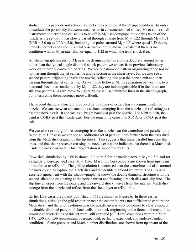
lines. It is clear that the width of this subsonic region is dominantly a function of the nozzle geometry and only weakly a function of pressure ratio. A higher design Mach number yields a narrower slip line. There is a slight reduction in the size of the subsonic region with increasing Mj. For the lowest pressure ratio for each nozzle, the cases where the lip shocks form Mach disks, a second slip line is generated by these external Mach disks. These external disks are larger in diameter than the internal ones and their slip lines surround the slip lines from inside the nozzle. For the Md = 1.5 nozzle this second slip line is also faintly visible in the shadowgraph Figure 4. The position of the initial throat wave reflection is shown in Figure 10. Md = 1.3 is omitted since the initial reflection for this case is inside the nozzle where we cannot see it. Again, the dominant parameter is the nozzle geometry, Md, but there is a weaker dependence on Mj which becomes stronger as Md rises. Figure 11 shows how the shock cell spacing is determined. The location of each reflection from the shear layer is plotted. The solid symbols are the lip waves and the open symbols are the throat waves. For this typical case only two throat reflections are distinct from the lip reflections. Past the second diamond the waves coalesce. Typically the shock cell spacing is not uniform. The points lie on a curve concave downward indicating that the shock cells become shorter as the flow develops. This is due to the thickening of the shear layers bringing the sonic lines closer together. As the lateral length scale is compressed by this, the longitudinal scale must also shrink in order to preserve the oblique shock and Prandtl-Meyer fan angles. Based on an examination of all the cases, five cells were selected to average to arrive at Ls the characteristic shock cell length. Beyond the fifth cell the shrinking of the cells becomes significant. The shock cell spacing, Ls is shown in Figure 12. Also shown are the theoretical values using the Prandtl-Pack relation .
1⁄ ⁄ , where 2.40483
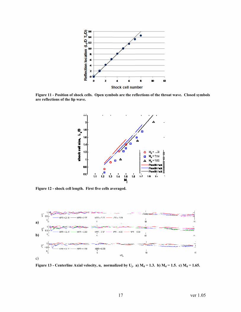
While the trends are the same, the shock cell spacing for this kind of nozzle is uniformly smaller than the values determined by this equation. The measured values range from 9% to 25% with most cases lying in the range from 10% to 20%. The centerline axial velocities are plotted in Figure 13. In this case they are normalized by the fully expanded velocity Uj = a • Mj. These plots show that the velocities begin to fall for all pressure ratios by around x/De = 7 for Md = 1.3 indicating the end of the potential core. Oscillation in center velocity continues past this point for the underexpanded cases, however, so the potential core is ending before the shock train ends. For Md = 1.5 the potential core appears to have ended by 8 De or so, but again, the shock cells extend further. For Md = 1.65 the potential core ends by 7 or 8 De but the oscillations in the underexpanded condition extend twice as far.

8 ver 1.05
The length of the shock train is easier to discern in the plots of the cross-stream velocity. The normalized cross-stream velocities for the three nozzles at their design condition are shown in Figure 14. Three Mj values are shown for the median nozzle in Figure 15. The double diamond features are evident here as well. The rms velocities along the nozzle lip line (r/De = 0.5) are shown in Figure 16 and Figure 17. The streamwise rms begins at 0.2 Ud for all cases an increases gradually to roughly 0.25 Ud by x/De = 15 for all cases. The cross-stream rms exhibits a similar trend of gradual increase, but its magnitude is less than half of the streamwise rms. For Md = 1.3 it begins at roughly 0.08 Ud and rises to 0.1 Ud. For Md = 1.5. and 1.65 the cross-stream rms begins slightly lower, around 0.06 or 0.07 Ud and increases to around 0.1Ud. The dips in the curves for the underexpanded cases are not due to reduced rms in the shear layer, but rather from departure of the shear layer from the line r/De = 0.5 as the jet becomes significantly underexpanded, the shock cells take on the classical barrel shape. As the shear layer expands in the middle of the cells it moves off the lip line, so the rms along the lip line is reduced except at the ends of the cells where they come back to the lip line. The PIV and shadowgraph measurements reveal no shock-free conditions above the pressure ratio at which shocks first form. Further evidence that no shock-free flow exists for this type of nozzle near the design condition lies in the acoustic measurements. Figure 18 shows the acoustic spectra observed in the far-field at an inlet angle of 35°. This is the angle at which both broad-band shock-associated noise and screech most strongly propagate. Each nozzle was operated at closely spaced nozzle pressure ratios and the far-field spectra were recorded. For all three nozzles the screech tones are very clear. They weaken somewhat near the design condition and appear to switch modes somewhat above the design condition, but they are never absent. The broad-band shock-associated noise is present and undiminished right through the neighborhood of the design condition. Discussion and Conclusion The conic C-D nozzles we study in this paper exhibit the features we expect of underexpanded or overexpanded jets from the more familiar contoured C-D nozzles. The overexpanded conditions generate a lip shock which evolves as we expect to produce shock cells. When the degree of overexpansion is high enough, a Mach disk forms outside the nozzle. The underexpanded conditions generate Prandtl-Meyer waves, which evolve as we expect to produce shock cells as well. When the degree of underexpansion is sufficiently high, we see the curved jet boundary forming barrel cells. No shock-free condition is present in jets from these nozzles above the pressure ratio at which shocks first form. This is confirmed by shadowgraph, PIV and acoustic measurement. Screech tones become somewhat weaker near the design NPR but do not vanish. There is a shift in frequency of the screech at an NPR slightly above the design condition indicating a change in oscillation mode. Broad-band shock-associated noise does not diminish near the design point. This is due to the non-parallel flow at the exit of these nozzles under all

9 ver 1.05
conditions. Since the expansion contour is conic, the flow exiting the outer edge of the nozzle will have a radially outward component of velocity under all conditions. In order to achieve parallel flow, there must be turning of a supersonic flow, and this will produce a shock even when the pressures are matched perfectly. These nozzles also produce shock cells from a second source. They produce shocks from the throat. For all three nozzles we examined ranging from Md = 1.3 to 1.65, these shocks formed a Mach disk inside the nozzle. These shocks emerged from the nozzle to reflect off of the shear layer as Prandtl-Meyer fans and set up shock cells of their own. This second set of shock cells is superimposed on the cells from the lip generating a double-diamond appearance. As the two shock-cell trains propagate downstream they eventually coalesce into a single set of shock cells after two or three cells. This second shock originating at the throat may be characterized by the diameter of the internal Mach disk and by the position of the first reflection of the throat wave back inward. Both of these parameters are strong functions of the nozzle geometry as expressed as Md and more weakly a function of the pressure inside the nozzle which may be expressed in terms of nozzle pressure ratio or fully expanded Mach number, Mj. LES captures the existence of the throat shocks and the internal Mach disk if the grid density is sufficient near the centerline in the nozzle. We have shown elsewhere [6] that the LES did capture most of the acoustic characteristics of this jet even when the internal Mach disk was not resolved. The turbulence intensity in the shear layers, expressed as rms velocity was 0.2Uj for fluctuations in the axial direction and 0.08Uj for fluctuations in the radial direction. Both increased farther downstream. By x/De = 15, the axial fluctuations had increased to 0.25Ud and the radial fluctuations increased to 0.1Ud. The size of the shock cells is smaller than those from an equivalent contoured nozzle. The shock cell size Ls follows the trends described in the Prandtl-Pack relationship, but in all cases the shock cell size was smaller than Prandtl-Pack predicts by 9% to 25%. Acknowledgements This work has been sponsored by the Strategic Environmental Research and Development Program (SERDP). The authors gratefully thank Dr. Ravi Ramamurti from the Naval Research Laboratory and Prof. Rainald Lohner from the George Mason University for their significant help with the computational code, FEFLO. They would also like to thank Dr. Steve Martens from GE Global Research for his guidance and advice in the design of realistic test cases and general insights into nozzle flow and acoustics. References 1. Meyer, T. (1908). Ueber zweidimensionale Bewegungsvorgaenge in einem Gas, das mit Ueberschallgeschwindigkeit stroemt. Dissertation, Goettingen.

10 ver 1.05
2. Munday, D., Gutmark, E., Liu J. and Kailasanath, K. (2008). “Flow and Acoustic Radiation from Realistic Tactical Jet C-D Nozzles.” 14th AIAA/CEAS Aeroacoustics Conference (29th AIAA Aeroacoustics Conference), May 5-7, 2008, Vancouver, British Columbia, AIAA-2008-2838. 3. Lohner, R. (1988), FEM-FCT: Combining unstructured grids with high resolution, Communications in Applied Numerical Methods, Vol 4, 717-729 4. Boris, J.P. and Book, D.L.(1973), Flux-corrected Transport I:SHASTA a fluid transport algorithm that works, Journal of Computational Physics, 11 38. 5. Grinstein, F.F. and Fureby, C. (2005), On Monotonically Integrated Large Eddy Simulation of Turbulent Flows Based on FCT Algorithms, Chapter 3 in Flux-Corrected Transport: Principles, Algorithms, and Applications , Eds., D. Kuzmin, R. Lohner, and S. Turek, Springer, pp. 79-104. 6. Liu, J., Kailasanath, K., Munday, D., Gutmark, E. and Lohner, R. (2009) “Large-Eddy Simulation of a Supersonic Jet and Its Near-Field Acoustic Properties - Methodology & Validation,” 47th AIAA Aerospace Sciences Meeting, 5 Jan 2009, Orlando, FL, AIAA-2009-500.

11 ver 1.05
Figure 3 – Unstructured tetrahedral grid. (a) Complete domain. (b) Nozzle exit detail.
(a) (b)
Figure 2 – Convergent-divergent nozzle installed. (a) complete test article. (b) close-up of nozzle.
(a) (b)
MD = 1.30
MD = 1.50
MD = 1.65
Figure 1 – Nozzles simulating the exhausts of tactical jets. (a) Cross sections of all four nozzles, (b) Exit details of the MD=1.65 nozzle.
(a) (b)

12 ver 1.05
Figure 4 – Convergent-divergent nozzle (MD=1.5) shadowgraph. One hundred images averaged to suppress turbulence and emphasize shock structures.
NPR = 2.50, MJ = 1.22
NPR = 3.00, MJ = 1.36
NPR = 3.50, MJ = 1.47
NPR = 4.00, MJ = 1.56
NPR = 4.50, MJ = 1.64
NPR = 5.00, MJ = 1.71

13 ver 1.05
(a)
Figure 6 – LES flow-field inside the nozzle and near the exit for MD = 1.50. (a) Static pressure, overexpanded pressure ratio, NPR = 3.50, MJ = 1.47. (b) Static pressure, perfectly expanded pressure ratio, NPR = 3.70, MJ = 1.56. (c) Static pressure, underexpanded pressure ratio, NPR = 4.00, MJ = 1.56. (d) Mach number, overexpanded pressure ratio, NPR = 3.50, MJ = 1.47. (e) Mach number, perfectly expanded pressure ratio, NPR = 3.70, MJ = 1.56. (f) Mach number, underexpanded pressure ratio, NPR = 4.00, MJ = 1.56.
(d)
(b) (c)
(e) (f)
Figure 5 – LES flow-field inside the nozzle and near the exit for MD = 1.50, MJ = 1.56.

14 ver 1.05
x/De
u/Ud
Figure 7 - Mean u for perfect expansion (Mj = Md), a) Md = 1.30. b) Md = 1.50. c) NPR = 3.25. d) Md = 1.65

15 ver 1.05
x/De
u/Ud
Figure 8 - Mean u, Md = 1.5. a) NPR = 2.50. b) NPR = 3.67. c) NPR = 5.00.

Figurinternand wappro
FigurThe re
e 9 – Width ofnal Mach disk weakly a functioximately 0.09
e 10 - Axial poeflections for
f the slip line, which shed it
ion of the nozz9, 0.06 and 0.04
osition of firstMd = 1.50 are
w, at x/De = 0t. It is dominazle pressure r45 De respecti
t throat reflecte taken from sh
16
0.125. The diaantly a functioratio. The diamively
tion, Ti. The rhadowgraph.
ameter of the son of the desigmeters for Md
reflections for For Md = 1.6
slip line indicagn Mach numbd = 1.3, 1.5 and
r Md = 1.30 ar65 they are tak
ver 1.0
ates the size ofber of the nozzd 1.65 are
e inside the noken from PIV.
05
f the zle,
ozzle. .
Figurare re
Figur
a)
b)
c)
Figur
e 11 - Positioneflections of th
e 12 - shock ce
e 13 - Centerl
n of shock cellshe lip wave.
ell length. Fir
ine Axial velo
s. Open symb
rst five cells av
ocity, u, norm
17
bols are the re
veraged.
alized by Uj.
eflections of th
a) Md = 1.3. b
he throat wave
b) Md = 1.5. c
ver 1.0
e. Closed sym
) Md = 1.65.
05
mbols

18 ver 1.05
x/De
v/Ud
Figure 14 - Mean v for perfect expansion, Mj = Md. a) Md = 1.30 b) Md = 1.50. c) Md = 1.65

19 ver 1.05
x/De
v/Ud
Figure 15 - Mean v, Md = 1.5. a) NPR = 2.50. b) NPR = 3.67. c) NPR = 5.00.

a)
b)
c)Figurc) Md
a)
b)
c)Figurc) Md
re 16 - Normd = 1.65
re 17 - Normd = 1.65.
malized strea
malized cross
mwise rms v
s-stream rms
20
velocity at y
s velocity at
y/De = 0.5. a
y/De = 0.5.
a) Md = 1.30.
a) Md = 1.3
ver 1.0
. b) Md = 1.
0. b) Md = 1
05
50.
1.50.

21 ver 1.05
Figure 18 - Far-field spectra at ψ = 35°. a) Md = 1.3. b) Md = 1.5. c) Md = 1.65.


