flow nets.ppt
51
Flow Nets
-
Upload
mekete-dessie -
Category
Documents
-
view
12 -
download
0
description
for reading
Transcript of flow nets.ppt

Flow Nets

Flow through a Dam
Drainageblanket
Phreatic line
UnsaturatedSoil
Flow of water
2
2
2
20
h
x
h
z
z
x

Graphical representation of solution
1. Equipotentials Lines of constant head, h(x,z)
Equipotential (EP)

Phreatic line
Flow line (FL)
2. Flow lines Paths followed by water particles - tangential to flow
Graphical representation of solution
Equipotential (EP)

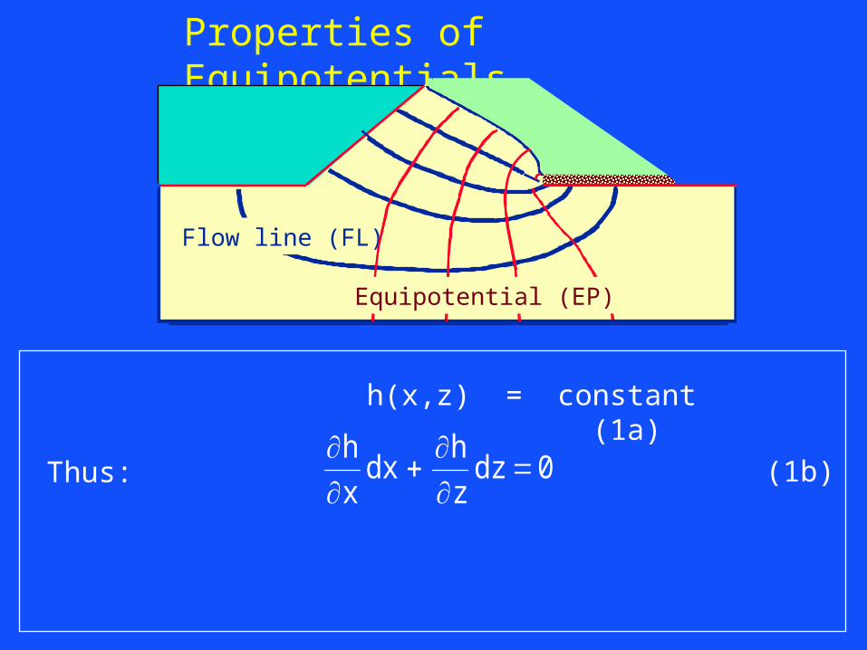
Properties of Equipotentials
h(x,z) = constant (1a)
Flow line (FL)
Equipotential (EP)
h(x,z) = constant (1a)
h
xdx
h
zdz 0Thus: (1b)
Properties of Equipotentials
Flow line (FL)
Equipotential (EP)

h(x,z) = constant (1a)
h
xdx
h
zdz 0Thus: (1b)
Equipotenial slopedz
dx
h x
h zEP
/
/(1c)
Properties of Equipotentials
Flow line (FL)
Equipotential (EP)

zx
Geometry
vzvx
Kinematics
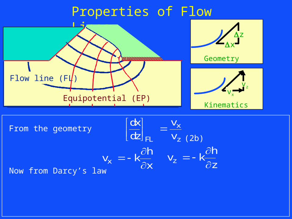
Properties of Flow Lines
From the geometry (2b)dx
dz
v
vFL
x
z
Flow line (FL)
Equipotential (EP)
zx
Geometry
vzvx
Kinematics
Properties of Flow Lines
From the geometry (2b)
Now from Darcy’s law
dx
dz
v
vFL
x
z
v kh
xx
v kh
zz
Flow line (FL)
Equipotential (EP)
zx
Geometry
vzvx
Kinematics
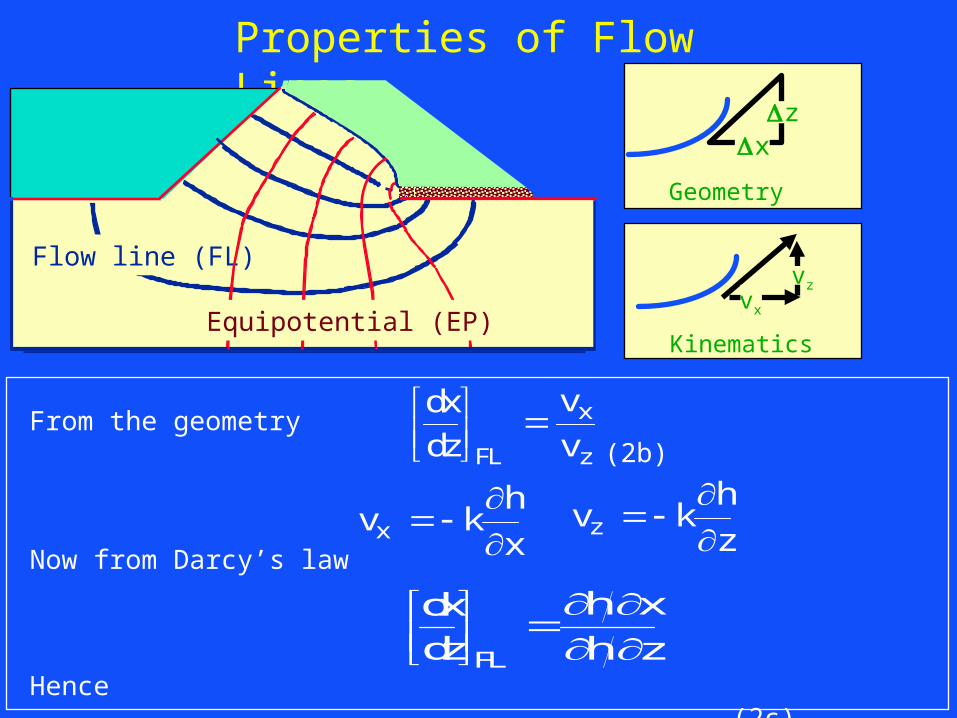
Properties of Flow Lines
From the geometry (2b)
Now from Darcy’s law
Hence (2c)
dx
dz
v
vFL
x
z
v kh
xx
dx
dz
h x
h zFL
v kh
zz
Flow line (FL)
Equipotential (EP)

Orthogonality of flow and equipotential lines
dz
dx
h x
h zEP
/
/
dx
dz
h x
h zFL
On an equipotential
On a flow line
Flow line (FL)
Equipotential (EP)

Orthogonality of flow and equipotential lines
dz
dx
h x
h zEP
/
/
dx
dz
h x
h zFL
On an equipotential
On a flow line
Hencedx
dz
dx
dzFL EP
1 (3)
Flow line (FL)
Equipotential (EP)

Q
X
y
z
t
T
Y
Z
X
FL
FL
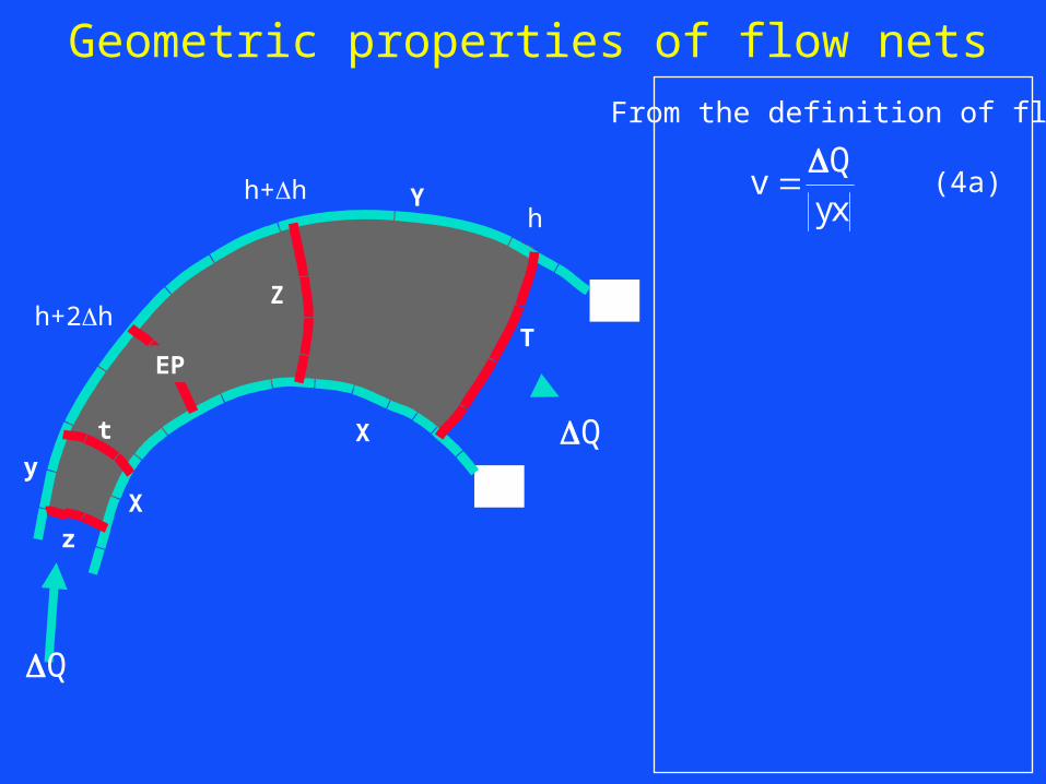
Geometric properties of flow nets
Q
hh+h
h+2h
EP
Q
X
y
z
t
T
Y
Z
X
FL
FL
vQ
yx
(4a)
From the definition of flow
Geometric properties of flow nets
Q
hh+h
h+2h
EP

Q
X
y
z
t
T
Y
Z
X
FL
FL
vQ
yx
v kh
zt
(4a)
(4b)
From the definition of flow
From Darcy’s law
Geometric properties of flow nets
Q
hh+h
h+2h
EP

Q
X
y
z
t
T
Y
Z
X
FL
FL
vQ
yx
v kh
zt
Q
k h
yx
zt
(4a)
(4b)
(4c)
From the definition of flow
From Darcy’s law
Combining (4a)&(4b)
Geometric properties of flow nets
Q
hh+h
h+2h
EP

Q
X
y
z
t
T
Y
Z
X
FL
FL
vQ
yx
v kh
zt
Q
k h
yx
zt
Q
k h
YX
ZT
(4a)
(4b)
(4c)
(4d)
From the definition of flow
From Darcy’s law
Combining (4a)&(4b)
Similarly
Geometric properties of flow nets
Q
hh+h
h+2h
EP

Q
X
y
z
t
T
Y
Z
X
FL
FL
vQ
yx
v kh
zt
Q
k h
yx
zt
Q
k h
YX
ZT
(4a)
(4b)
(4c)
(4d)
From the definition of flow
From Darcy’s law
Combining (4a)&(4b)
Similarly
Geometric properties of flow nets
Q
hh+h
h+2h
EP
Conclusion
yx
zt
YX
ZT (5)

Q
a
b
c
d
D
B
C
A
h
h h
Geometric properties of flow nets
FL
Q
EP( h )
EP ( h + h )

vQ
cd
(6a)
From the definition of flow
Q
a
b
c
d
D
B
C
A
h
h h
Geometric properties of flow nets
FL
Q
EP( h )
EP ( h + h )

vQ
cd
v kh
ab
(6a)
(6b)
From the definition of flow
From Darcy’s lawQ
a
b
c
d
D
B
C
A
h
h h
Geometric properties of flow nets
FL
Q
EP( h )
EP ( h + h )

vQ
cd
Q
k h
cd
ab
v kh
ab
Q
k h
CD
AB
(6a)
(6b)
(6c)
(6d)
From the definition of flow
From Darcy’s law
Similarly
Combining (6a)&(6b)
Q
a
b
c
d
D
B
C
A
h
h h
Geometric properties of flow nets
FL
Q
EP( h )
EP ( h + h )

vQ
cd
Q
k h
cd
ab
v kh
ab
Q
k h
CD
AB
(6a)
(6b)
(6c)
(6d)
From the definition of flow
From Darcy’s law
Similarly
Combining (6a)&(6b)
Conclusioncd
ab
CD
AB
Q
a
b
c
d
D
B
C
A
h
h h
Geometric properties of flow nets
FL
Q
EP( h )
EP ( h + h )

• When drawing flow nets by hand it is most convenient to draw them so that
• Each flow tube carries the same flow Q• The head drop between adjacent EPs, h, is the
same
• Then the flow net is comprised of “SQUARES”
Geometric properties of flow nets

Geometric properties of flow nets
Demonstration of ‘square’ rectangles with inscribed circles

Drawing Flow Nets
To calculate the flow and pore pressures in the ground a flow net must be drawn.
The flow net must be comprised of a family of orthogonal lines (preferably defining a square mesh) that also satisfy the boundary conditions.

Water
Datum
H-z
z
H
(7)
Common boundary conditionsa. Submerged soil boundary - Equipotential
hu
zw
w

Water
Datum
H-z
z
H
(7)
Common boundary conditionsa. Submerged soil boundary - Equipotential
hu
z
now
u H z
w
w
w w
( )

Water
Datum
H-z
z
H
(7)
Common boundary conditionsa. Submerged soil boundary - Equipotential
hu
z
now
u H z
so
hH z
z H
w
w
w w
w
w
( )
( )

Permeable Soil
Flow Linevn=0
vt
Impermeable Material
Common boundary conditionsb. Impermeable soil boundary - Flow Line

Common boundary conditionsc. Line of constant pore pressure - eg. phreatic surface
hu
zw
w
Head is given by

Common boundary conditionsc. Line of constant pore pressure - eg. phreatic surface
hu
zw
w
hu
zw
w
Head is given by
and thus

Common boundary conditionsc. Line of constant pore pressure - eg. phreatic surface
hu
zw
w
hu
zw
w
uw
0
Head is given by
and thus
now if pore pressure is constant

Common boundary conditionsc. Line of constant pore pressure - eg. phreatic surface
hu
zw
w
hu
zw
w
h z
uw
0
Head is given by
and thus
now if pore pressure is constant
and hence (8)

Common boundary conditionsc. Line of constant pore pressure - eg. phreatic surface

Procedure for drawing flow nets
• Mark all boundary conditions
• Draw a coarse net which is consistent with the boundary conditions and which has orthogonal equipotentials and flow lines. (It is usually easier to visualise the pattern of flow so start by drawing the flow lines).
• Modify the mesh so that it meets the conditions outlined above and so that rectangles between adjacent flow lines and equipotentials are square.
• Refine the flow net by repeating the previous step.

Value of head on equipotentials
Phreatic line
hH
Numberofpotentialdrops (9)
Datum
15 m
h = 15m
h = 12m h = 9m h = 6mh = 3m
h = 0

For a single Flow tube of width 1m: Q = k h (10a)
Calculation of flowPhreatic line
15 m
h = 15m
h =12m h = 9m h = 6mh = 3m
h = 0

For a single Flow tube of width 1m: Q = k h (10a)
For k = 10-5 m/s and a width of 1m Q = 10-5 x 3 m3/sec/m (10b)
Calculation of flowPhreatic line
15 m
h = 15m
h =12m h = 9m h = 6mh = 3m
h = 0

For a single Flow tube of width 1m: Q = k h (10a)
For k = 10-5 m/s and a width of 1m Q = 10-5 x 3 m3/sec/m (10b)
For 5 such flow tubes Q = 5 x 10-5 x 3 m3/sec/m (10c)
Calculation of flowPhreatic line
15 m
h = 15m
h =12m h = 9m h = 6mh = 3m
h = 0

For a single Flow tube of width 1m: Q = k h (10a)
For k = 10-5 m/s and a width of 1m Q = 10-5 x 3 m3/sec/m (10b)
For 5 such flow tubes Q = 5 x 10-5 x 3 m3/sec/m (10c)
For a 25m wide dam Q = 25 x 5 x 10-5 x 3 m3/sec (10d)
Calculation of flowPhreatic line
15 m
h = 15m
h =12m h = 9m h = 6mh = 3m
h = 0
Q kH
NN
hfNote that per metre width (10e)

P5m
hu
zw
w
(11a)
Calculation of pore pressurePhreatic line
P5m
Pore pressure from
15 m
h = 15m
h = 12m h = 9m h = 6mh = 3m
h = 0

P5m
hu
zw
w
(11a)
uw w [ ( )]12 5 (11b)
Calculation of pore pressurePhreatic line
P5m
Pore pressure from
At P, using dam base as datum
15 m
h = 15m
h = 12m h = 9m h = 6mh = 3m
h = 0

StrandedVessel
WaterSupply
SoftSeaBottom
WellPoint
ReactionPile
Example Calculating Pore Pressures
20 m
10 m


Step 1: Choose a convenient datum. In this example the sea floor has been chosen
Then H1 = 40 mH2 = 1 m.
The increment of head, h = 39/9 = 4.333 m

A B C D E
Step 2: Calculate the head at points along the base of the vessel. For convenience these are chosen to be where the EPs meet the vessel (B to E) and at the vessel centerline (A). Hence calculate the pore water pressures.
At B Head = H1 - 5 h = H2 + 4 h = 18.33 m
Pore pressure at B = 18.33 w = 179.8 kPaww zhu )]([

Step 3: Calculate the upthrust (Force/m) due to pore pressures
7.02
3.529.948.1
2
9.943.1375.2
2
3.1378.1795
2
8.1791.2012
= 3218 kN/m
Without pumping Upthrust = 20 1 9.81 = 196 kN/m
Upthrust due to Pumping = 3218 – 196 = 3022 kN/m
0
50
100
150
200
250
0 1 2 3 4 5 6 7 8 9 10
Distance from centreline (m)
Po
re W
ate
r P
res
su
re (
kP
a)

Flow required, h
f
N
NHkQ = 24 108.1
9
1439103 m3/m/sec