Flow around a two dimensional cylinder - LS-DYNA … around a two dimensional cylinder ... Metadata...
15
TEST CASE DOCUMENTATION AND TESTING RESULTS TEST CASE ID ICFD-VAL-3.1 Flow around a two dimensional cylinder Tested with LS-DYNA R v980 Revision Beta Friday 1 st June, 2012
Transcript of Flow around a two dimensional cylinder - LS-DYNA … around a two dimensional cylinder ... Metadata...

TEST CASE DOCUMENTATION
AND TESTING RESULTS
TEST CASE ID ICFD-VAL-3.1
Flow around a two dimensional cylinder
Tested with LS-DYNA R© v980 Revision Beta
Friday 1st June, 2012
Document Information
Confidentiality external use
Document Identifier LSTC-QA-LS-DYNA-ICFD-VAL-3.1-1
Author(s) Inaki Caldichoury, Facundo Del Pin
Number of pages 12
Date created Friday 1st June, 2012
Distribution External
Disclaimer:
The test case(s) described herein are for illustrative purposes only. LSTCdoes not warrant that a user of these or other LS-DYNA features will expe-rience the same or similar results or that a feature will meet the user’s par-ticular requirements or operate error free. FURTHERMORE, THERE ARENO WARRANTIES, EITHER EXPRESS OR IMPLIED, ORAL OR WRIT-TEN, WITH RESPECT TO THE DOCUMENTATION AND SOFTWAREDESCRIBED HEREIN INCLUDING, BUT NOT LIMITED TO ANY IM-PLIED WARRANTIES (i) OF MERCHANTABILITY, OR (ii) FITNESSFOR A PARTICULAR PURPOSES, OR (iii) ARISING FROM COURSEOF PERFORMANCE OR DEALING, OR FROM USAGE OF TRADE OR.THE REMEDIES SET FORTH HEREIN ARE EXCLUSIVE AND IN LIEUOF ALL OTHER REMEDIES FOR BREACH OF WARRANTY.
LSTC-QA-LS-DYNA-ICFD-VAL-3.1-1 i

Contents
1 Introduction 11.1 Purpose of this Document . . . . . . . . . . . . . . . . . . . . . . . . . . . . 1
2 Test Case Information 2
3 Test Case Specification 33.1 Test Case Purpose . . . . . . . . . . . . . . . . . . . . . . . . . . . . . . . . 33.2 Test Case Description . . . . . . . . . . . . . . . . . . . . . . . . . . . . . . . 43.3 Model Description . . . . . . . . . . . . . . . . . . . . . . . . . . . . . . . . 6
4 Test Case Results 84.1 Test Case observations . . . . . . . . . . . . . . . . . . . . . . . . . . . . . . 8
ii LSTC-QA-LS-DYNA-ICFD-VAL-3.1-1
1 Introduction
1.1 Purpose of this Document
This document specifies the test case ICFD-VAL-3.1. It provides general test case informa-tion like name and ID as well as information to the confidentiality, status, and classificationof the test case.
A detailed description of the test case is given, the purpose of the test case is defined, and thetested features are named. Results and observations are stated and discussed. Testing resultsare provided in section 4.1 for the therein mentioned LS-DYNA R© version and platforms.
LSTC-QA-LS-DYNA-ICFD-VAL-3.1-1 1
2 Test Case Information
Test Case Summary
Confidentiality external use
Test Case Name Flow around a two dimensional cylinder
Test Case ID ICFD-VAL-3.1
Test Case Status Under consideration
Test Case Classification Validation
Metadata EXTERNAL FLOW
Table 1: Test Case Summary
2 LSTC-QA-LS-DYNA-ICFD-VAL-3.1-1

3 Test Case Specification
3.1 Test Case Purpose
The purpose of this test case is to show the solver’s ability to correctly reproduce the station-nary and the unstationnary incompressible laminar flow around a cylinder for a Reynoldsnumber up to 160.
LSTC-QA-LS-DYNA-ICFD-VAL-3.1-1 3

3.2 Test Case Description
The flow around a cylinder has been widely used both as a numerical validation test caseas well as a research case (See [3], [1]). The behavior of the flow is characterized by theReynolds number defined as :
Re =ρLV
ν(1)
with ρ the fluid’s density, L the characteristic length of the problem i.e the diameter of thecylinder, V the incoming velocity and ν the fluid’s viscosity.
Depending on the Reynolds number, the following behaviors of the flow can be identified :
Re < 50 Steady laminar flow with symmetric separation (see Figure (1)).
50 < Re < 160 − 190 Karman Vortex street (see Figure (2)).
190 < Re < 300 Laminar with vortex street instabilities.
300 < Re Laminar-Turbulent transition. Turbulent separation
and reattachment, Turbulent wake.
This test case will focus on the laminar regime. The Reynolds number will be varied from 2to 160. According to the available literature, this study will especially focus on two valuesof viscosity corresponding to the Reynolds number values of Re = 40 and Re = 100. For allcases, the values of pressure and lift will be compared to those available in the literature.For the Re = 40 case, the boundary layer separation point of the laminar stationary flowwill be analyzed as well as the reattachment length. For the Re = 100 case, the frequencyof the vortex shedding will be studied through the Strouhal number defined as :
St =DU
T(2)
with D the diameter of the cylinder, U the incoming velocity, and T the oscillations’ period.
4 LSTC-QA-LS-DYNA-ICFD-VAL-3.1-1
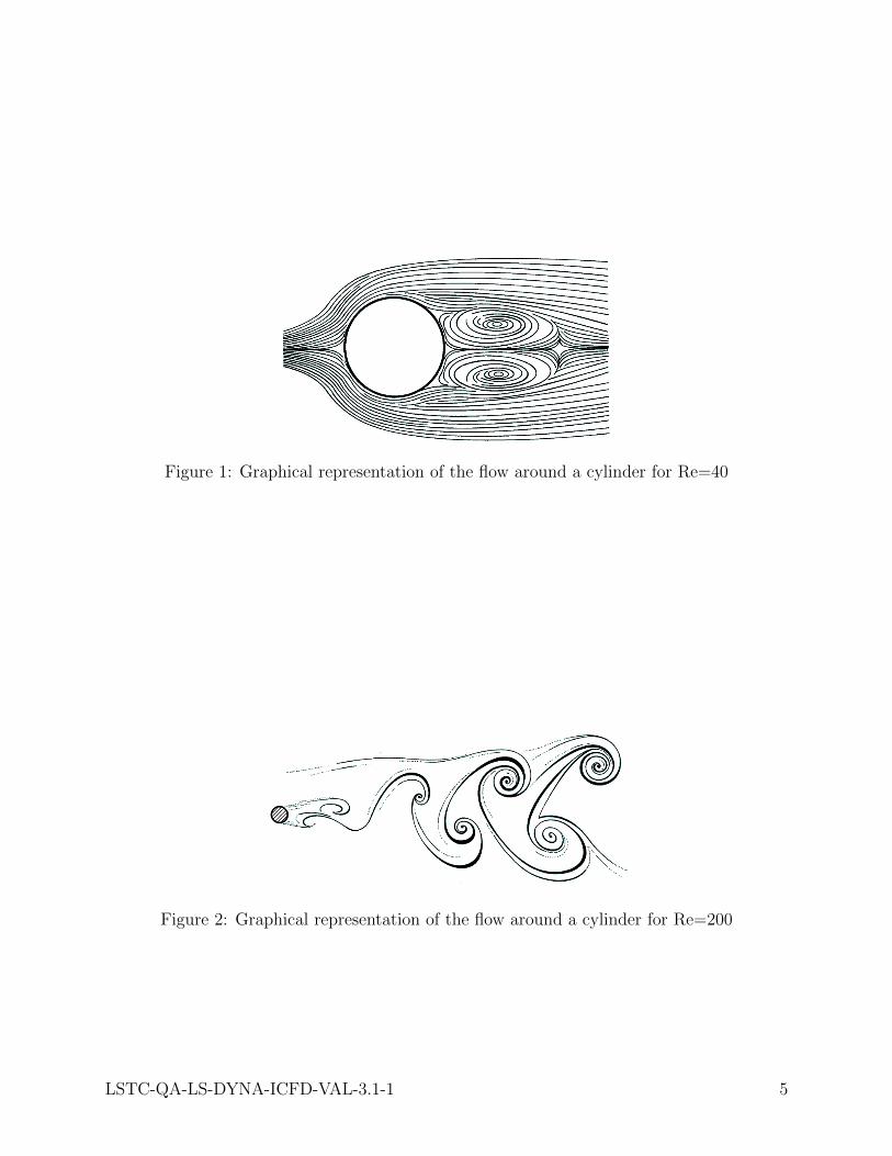
Figure 1: Graphical representation of the flow around a cylinder for Re=40
Figure 2: Graphical representation of the flow around a cylinder for Re=200
LSTC-QA-LS-DYNA-ICFD-VAL-3.1-1 5
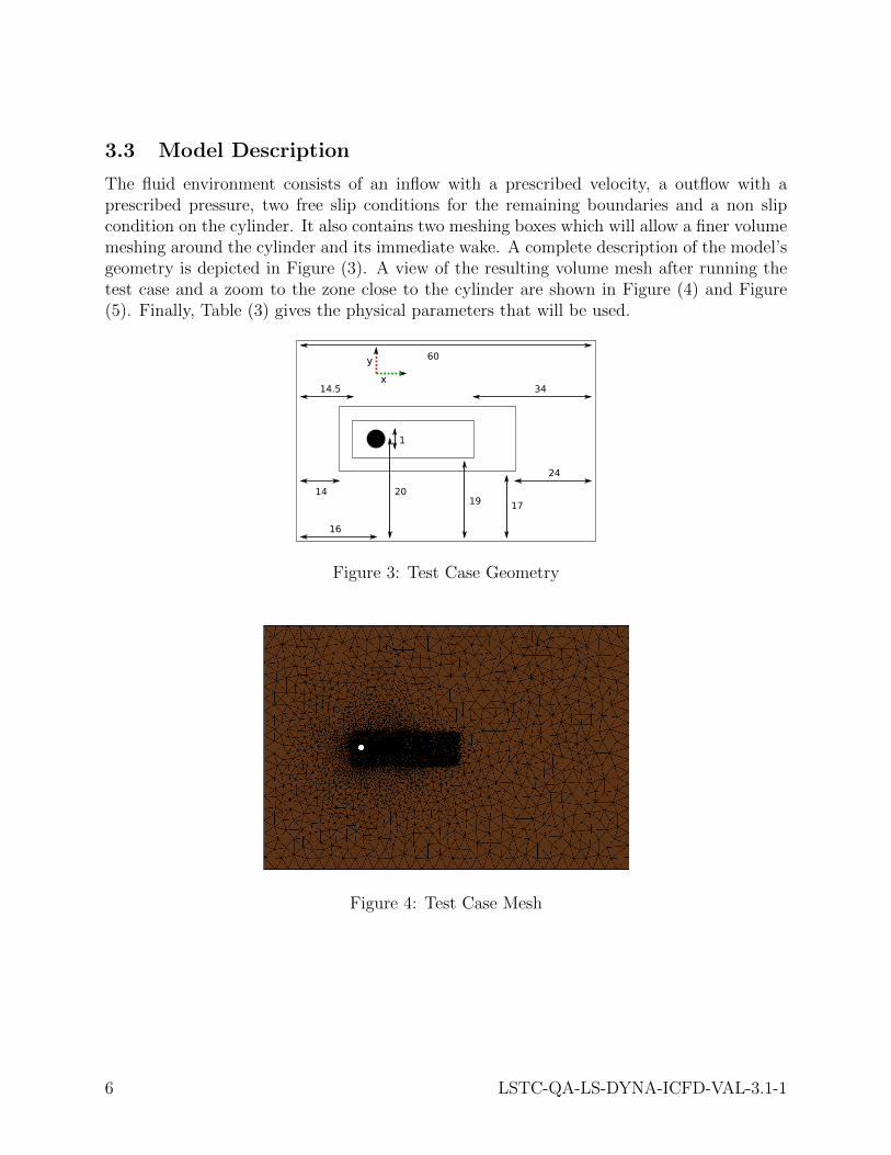
3.3 Model Description
The fluid environment consists of an inflow with a prescribed velocity, a outflow with aprescribed pressure, two free slip conditions for the remaining boundaries and a non slipcondition on the cylinder. It also contains two meshing boxes which will allow a finer volumemeshing around the cylinder and its immediate wake. A complete description of the model’sgeometry is depicted in Figure (3). A view of the resulting volume mesh after running thetest case and a zoom to the zone close to the cylinder are shown in Figure (4) and Figure(5). Finally, Table (3) gives the physical parameters that will be used.
60
20
16
14.5
14
1
34
24
1719
x
y
Figure 3: Test Case Geometry
Figure 4: Test Case Mesh
6 LSTC-QA-LS-DYNA-ICFD-VAL-3.1-1

Figure 5: Zoom of the Mesh close to the cylinder
Model information
Fluid boundaries element size 2
Cylinder element size 0.01
Meshing box 1 & 2 element size 0.1 & 0.025
Volume Nodes 45383
Volume Elements 88626
Anisotropic Elements added to the Bound-ary Layer
3
Table 2: Test Case Mesh Information
Model physical parameters
Fluid Density 1
Viscosity 0.5 to 0.00625
Incomming velocity 1
Table 3: Test Case Parameters
LSTC-QA-LS-DYNA-ICFD-VAL-3.1-1 7

4 Test Case Results
4.1 Test Case observations
Figure (6) shows the velocity vectors for a Reynolds number of 40 highlighting the steadylaminar symmetric separation occurring behind the cylinder. Figure (7) shows the velocityvectors for a Reynolds number of 100 highlighting the periodic Von Karman vortex shedding.Table (4) gives the lift and drag results obtained for the various Reynolds numbers. The liftvalues correspond to the maximum lift values occurring during the vortex shedding. Startingfrom the Reynolds value of 60, the drag values given are mean drag values calculated afterthe vortex shedding is fully developed.
Figure (8) and (9) offer a comparison between the present analysis and the results given by[2]. It can be noted that the global behavior of the present analysis is in good agreementwith the reference results. Starting from the Reynolds number of 40, the error regarding thetotal drag slowly expands going from 3.8% for Re = 40 to 7.5% for Re = 2 when comparingwith the results given by [2]. This can be explained by the fact that, as the Reynolds numberdecreases and the viscosity increases, the hypothesis used by the Fractional Step method ofthe solver, (i.e the diffusion term of the solution due to the viscosity is small compared to theconvection term) is slowly reaching its limits. It can also be noted that the the error regard-ing the lift coefficient slowly increases going from 4.1% for Re = 80 to 6.6% for Re = 160.In order to bring this error down, a finer mesh may be used. For illustration purposes, Table(5) offers a mesh grid convergence analysis for a Reynolds number of 100 using the referenceresult for error calculation given by [2].
Finally, for the Reynolds numbers of 40 and 100, some further observations can be made.For the Reynolds number of 40, the boundary layer separation angle occurs at an angle of54◦ and the distance between the flow reattachment point and the cylinder is equal to 2.3which is in good agreement with the results given by [2]. For the Reynolds number of 100,the Strouhal number is equal to 0.165 which is in the vicinity of the results given by [2] and[3] (see Table (6)).
8 LSTC-QA-LS-DYNA-ICFD-VAL-3.1-1

Figure 6: Velocity vectors for Re = 40
Figure 7: Velocity vectors for Re = 100
LSTC-QA-LS-DYNA-ICFD-VAL-3.1-1 9

Results for the Drag and Lift coefficients
Reynolds Cdtot Cdpres Cdfric Cltot Clpres Clfric
2 7.36 3.74 3.62
4 4.83 2.54 2.29
10 2.92 1.63 1.29
20 2.10 1.25 0.84
40 1.57 1.02 0.55
60 1.44 0.99 0.45 0.14 0.12 0.0250
80 1.40 1.00 0.40 0.25 0.22 0.0396
100 1.38 1.02 0.36 0.35 0.30 0.0480
120 1.37 1.03 0.33 0.43 0.37 0.0562
140 1.37 1.05 0.31 0.51 0.45 0.0620
160 1.37 1.07 0.30 0.59 0.52 0.0674
Table 4: Test Case Lift and Drag results
Total Drag
Coefficient
Reynolds number
Figure 8: Comparison of the Total Drag between the present analysis (in red) and the results(in blue) given by [2]
10 LSTC-QA-LS-DYNA-ICFD-VAL-3.1-1

Reynolds number
Total Lift
Coefficient
Figure 9: Comparison of the Total Lift between the present analysis (in red) and the results(in blue) given by [2]
Cylinder surface elementsize
Cltot Error
0.02 0.357 7.6%
0.01 0.346 4.2%
0.005 0.337 1.4%
0.0025 0.336 1.2%
Table 5: Mesh grid analysis for Re = 100
Simo,
Armero
(1994)
Tezduyar
et al.(1991)
Choi et al.
(1997)
Mittal
(1993)
Brooks,Hughes
(1982)
Behr et al.
(1995)
St 0.167-0.178
0.156-0.170
0.164 0.167 0.167 0.162-0.171
Table 6: Results given by different authors for the Strouhal number and Re = 100
LSTC-QA-LS-DYNA-ICFD-VAL-3.1-1 11

References
[1] J. G. C. Y. Zhou, A numerical study of cylinders in waves and currents, Journal ofFluids and Structures, 14.
[2] H. C. Jeongyoung Park, Kiyoung Kwon, Numerical solutions of flow past a cir-cular cylinder at reynolds numbers up to 160, KSME International Journal, 12.
[3] W. A. Wall, Fluid Struktur Interaktion mit stabilisierten Finiten Elementen, PhDthesis, Universitat Stuttgart Institut fur Baustatik, 1999.
12 LSTC-QA-LS-DYNA-ICFD-VAL-3.1-1