
FloormapVS2i
47
FloormapVS2i
-
Upload
remedios-kelley -
Category
Documents
-
view
17 -
download
0
description
FloormapVS2i. FloormapVS2i. Computerized Magnetic Flux Leakage Tank Bottom Inspection System. FloormapVS2i. The battery powered, motorised scanner is complimented by the powerful, yet easy to use software. FloormapVS2i. - PowerPoint PPT Presentation
Transcript of FloormapVS2i

FloormapVS2i
FloormapVS2i
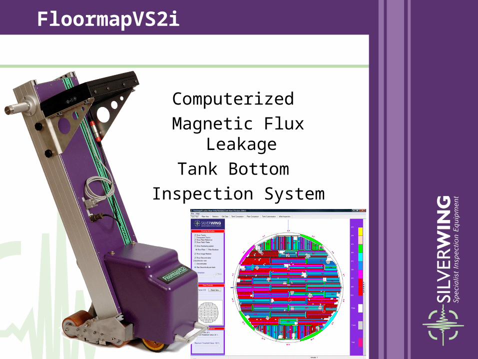
Computerized
Magnetic Flux Leakage
Tank Bottom
Inspection System

The battery powered, motorised scanner
is complimented
by the powerful,
yet easy to use
software.
FloormapVS2i
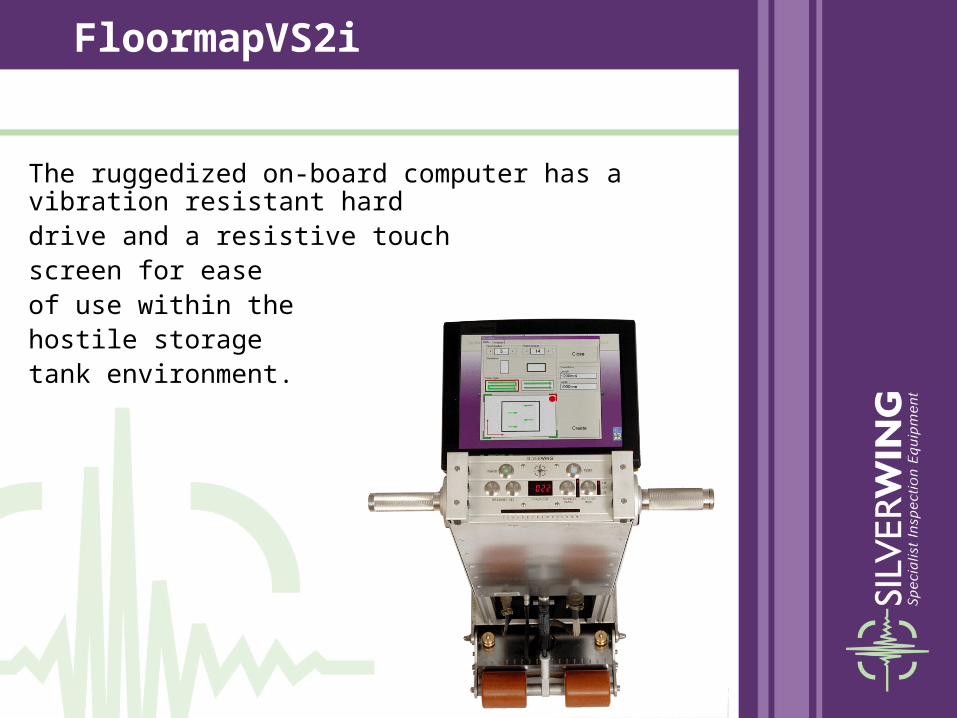
The ruggedized on-board computer has a vibration resistant hard drive and a resistive touch screen for ease of use within the hostile storage tank environment.
FloormapVS2i

A new encoder system has been developed, giving positional accuracy to within 3mm on an 8 metre track length.
FloormapVS2i

Powerful, easy to use software simplifies data collection, data analysis and reporting.
FloormapVS2i

Photographs and results from other inspections can easily be added to the FloormapVS2i report to show total tank floor condition.
FloormapVS2i

The FloormapVS2i
is the most operator friendly,
comprehensive tank floor inspection system available today.
FloormapVS2i
Magnetic Flux
Leakage
FloormapVS2i
Basic Principles

The following slides demonstrate the basic
principles of MFL for the detection of corrosion on
tank bottoms as used on the FloormapVS2i …..
Basic Principles of MFL

The FloormapVS2i uses powerful permanent rare earth magnets,
which achieve local magnetic saturation
of the tank floor plates
Permanent Magnets
Basic Principles of MFL

An array of 36 Hall effect sensors
are mounted between the
2 magnet poles
Sensor Array
Basic Principles of MFL

Basic Principles of MFL
The powerful magnet induces a uniform magnetic field close to saturation in the plate
When corrosion is encountered the magnetic field is forced outside the plate
The magnetic leakage field is detected by the hall-effect sensors and converted to an electrical signal

All MFL signals are filtered, amplified and combined with positional information from the optical encoder before being stored on the on-board computer.
Basic Principles of MFL
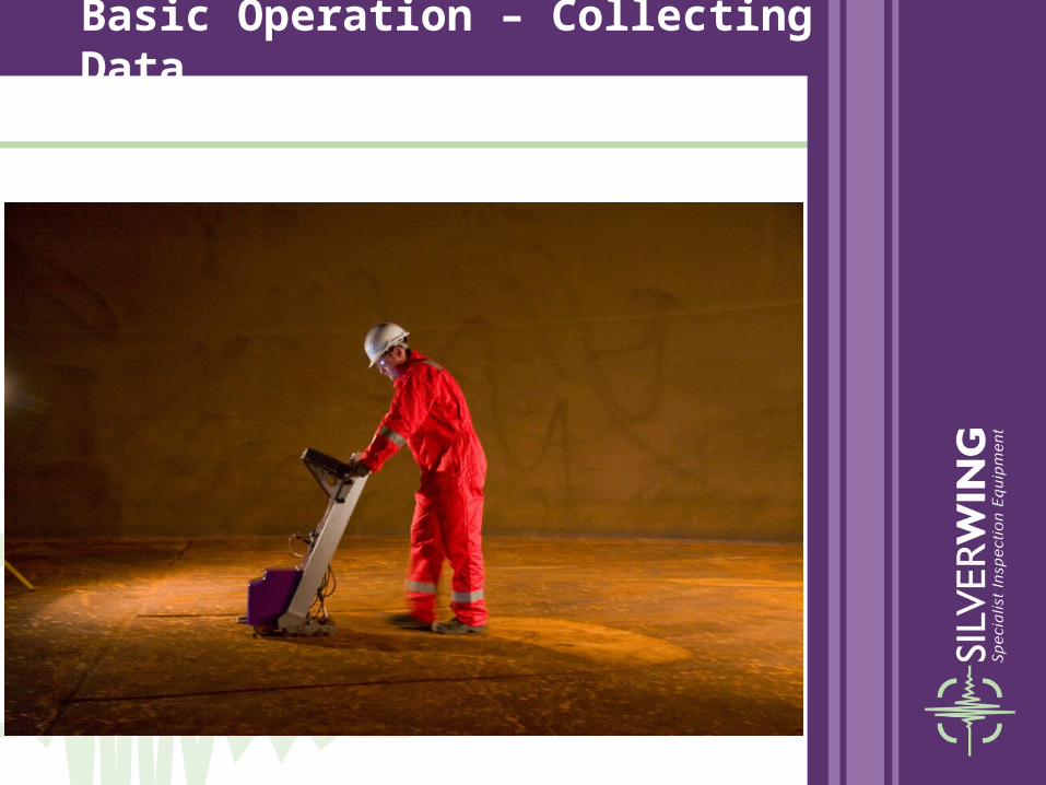
Basic Operation – Collecting Data

• The FloormapVS2i must be calibrated on a MFL reference plate before being used for an inspection.• The calibration procedure has been simplified to
minimise operator error
Basic Operation – Collecting Data

• All operator controls are easily accessible and simple to use.
Basic Operation – Collecting Data
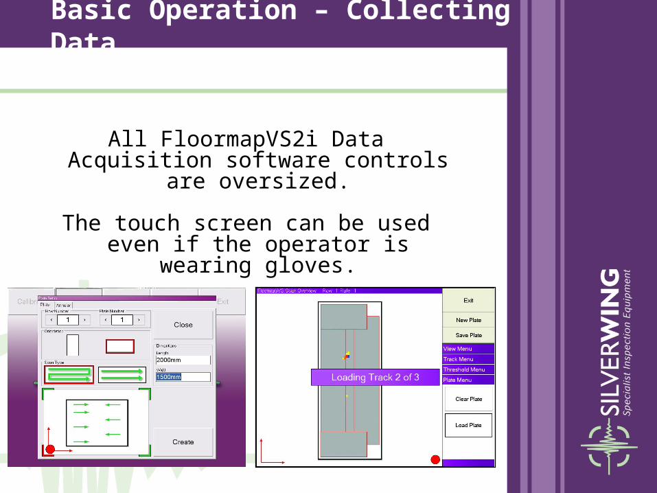
All FloormapVS2i Data Acquisition software controls are oversized.
The touch screen can be used even if the operator is wearing gloves.
Basic Operation – Collecting Data

• All scanning options are shown as graphical images to increase production rates and help minimise operator error.
Basic Operation – Collecting Data

• Each plate is scanned in a pre-set pattern until the entire plate has been covered.• The width of each scan is 250mm• Maximum single scan length of 15M• Speed of 0.45M per second
Basic Operation – Collecting Data

The FloormapVS2i Data Acquisition software captures the MFL signals and displays the location and severity of the
corrosion on screen.
Basic Operation – Collecting Data
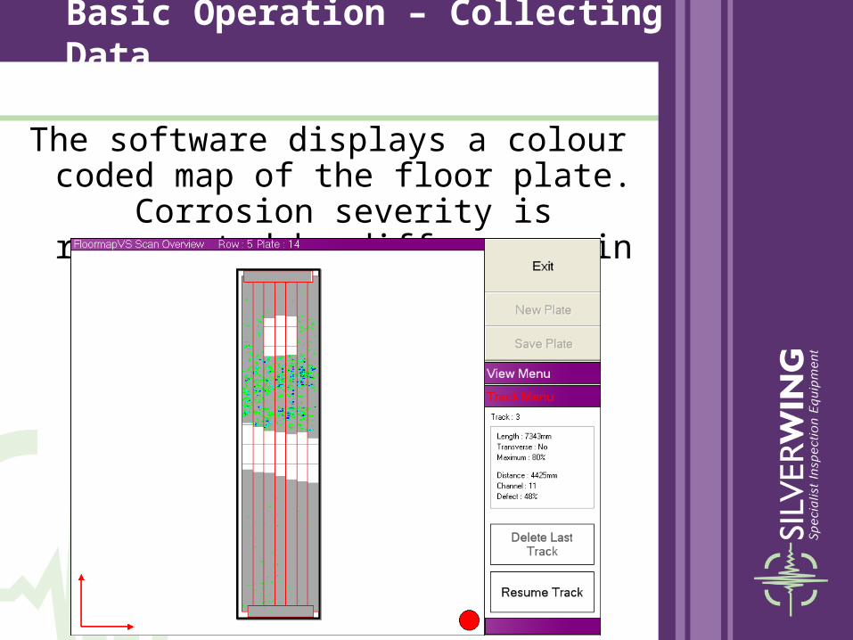
The software displays a colour coded map of the floor plate. Corrosion severity is represented by differences in colour.
Basic Operation – Collecting Data

• The user can filter the level of corrosion so only relevant defects are displayed on screen.
Basic Operation – Collecting Data

• More specific corrosion information can be seen by holding the cursor over the corrosion.
Basic Operation – Collecting Data
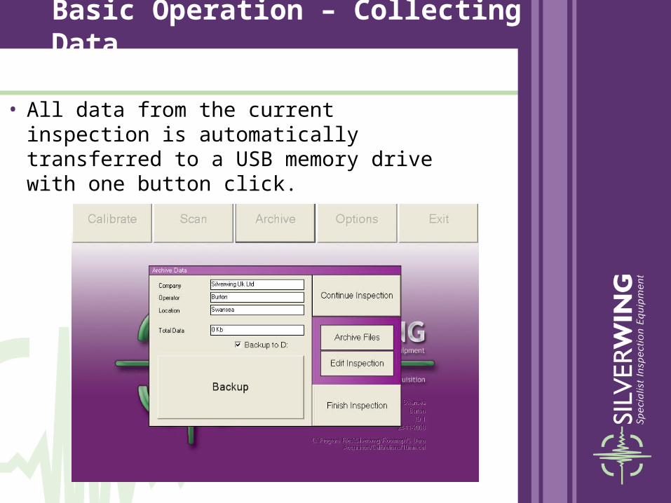
• All data from the current inspection is automatically transferred to a USB memory drive with one button click.
Basic Operation – Collecting Data
Reporting Software
Reporting Software

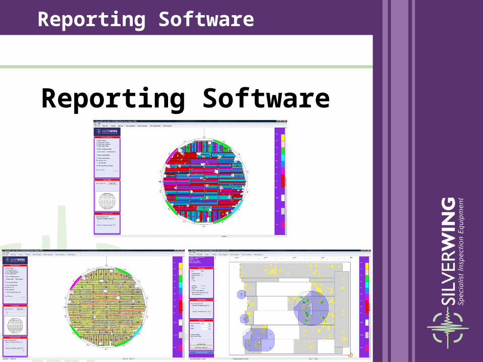
• Once the inspection is complete, the Floormap data is imported into the offline reporting software.
• There are 2 versions of the reporting software:• FULL version - designed for use by the Floormap
operator provides complete control to all data manipulation and evaluation tools.
• Read Only version - designed to be issued to end clients locks the inspection data, while providing full access to all of the useful evaluation tools, data comparison tools and patch plate
design tools.
Reporting Software
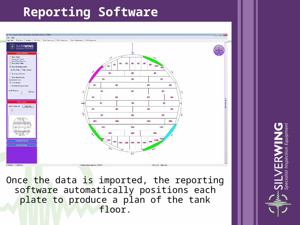
Once the data is imported, the reporting software automatically positions each plate
to produce a plan of the tank floor.
Reporting Software
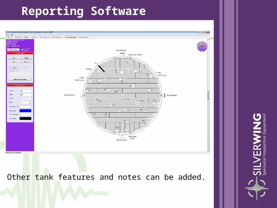
Other tank features and notes can be added.
Reporting Software
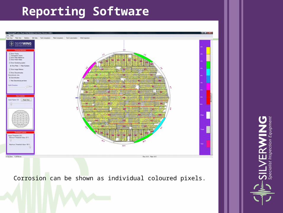
Corrosion can be shown as individual coloured pixels.
Reporting Software
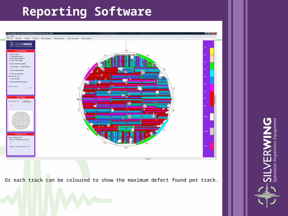
Or each track can be coloured to show the maximum defect found per track.
Reporting Software
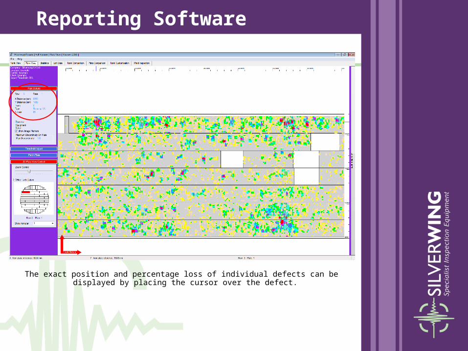
The exact position and percentage loss of individual defects can be displayed by placing the cursor over the defect.
Reporting Software

Digital images can be linked to specific areas of the plate.
Reporting Software

The software features a powerful patch repair design tool.
Reporting Software

Defects from any other inspectionscan be added to the tank floor report.
Reporting Software

Weld inspections can also be added with additional comments.
Reporting Software
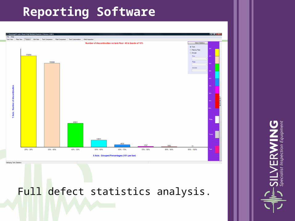
Full defect statistics analysis.
Reporting Software

Easy to use, powerful, customizable report configuration.
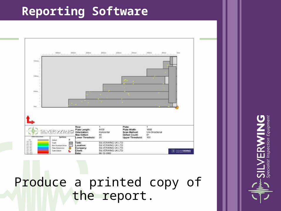
Reporting Software

Produce a printed copy of the report.
Reporting Software

Produce a printed copy of the report.
Reporting Software
Produce a printed copy of the report.
Reporting Software

Issue an electronic report
An electronic copy of the report can be issued to the customer along with the
read-only version of the reporting software.
The read only reporting software locks the data to prevent accidental editing, but
still allows the user to access the powerful reporting tools.
Reporting Software

• Thickness range: Maximum 12.5mm (automated sizing mode)
Maximum 20mm (detection mode only)
• Max sensitivity: 20% under floor corrosion
• Maximum coating thickness:6mm
• Scan width: 250mm
• Maximum single scan length:15 metres
• Speed: 0.5m/ sec
• Power requirements: 12v battery operation - Supplied with 3 batteries and 2 chargers to allow continuous working
FloormapVS2i - Specification

Floor plate cleaned to bare metal using high pressure washing
Floor cleaned to acceptable standard – some thin scale remaining
Generally acceptable – some spurious results possible from blisters
Floor acceptable – top surface pitting now visible
Surface Preparation RequirementsAcceptable Floor Conditions

Surface Preparation Requirements
Product residue and hardened scale present
60mm thick layer of product residue Hardened scale and loose corrosion products
Thick layer of scale present
Not Acceptable Floor Conditions

We are convinced that the powerful reporting software coupled with the advanced
FloormapVS2i scanner makes this the best tank bottom inspection
system on the market today.
FloormapVS2i

www.silverwinguk.com
NOT OPERATOR DEPENDENTTECHNOLOGY DRIVEN
Silverwing


