Floor Watering Manaual 06.06 - LubingUSA · FLOOR WATERING INSTALLATION GUIDE instruction #...
23
Watering Systems. Floor Watering Systems Installation Guide For the following systems: Broilers, Breeders, Pullets, with LitterGard Cups and without Instruction # IM-030-05 06/06
Transcript of Floor Watering Manaual 06.06 - LubingUSA · FLOOR WATERING INSTALLATION GUIDE instruction #...

WateringSystems.
Floor Watering Systems Installation Guide
For the following systems:
Broilers, Breeders, Pullets, with LitterGard Cups and without
Instruction # IM-030-05
06/06

F L O O R W AT E R I N G I N S TA L L AT I O N G U I D E
instruction # IM-030-05 06/06
System Overview
Please review this entire manual before
starting the installation to familiarize yourself
with the installation process.
Pictured below is an overview drawing of a
complete watering system showing optional
hose attachments. Lubing watering systems
are available with Pressure Regulators or Ball
Tank assemblies.
Pressure Regulators are designed with single
and double outlet capabilities. The illustration
below shows the regulator at the beginning of
the line. The Pressure Regulator may also be
used in the middle of the house with a double
outlet configuration depending on the house
length and slope.
Variations of these configurations are possible
depending on the customers’ needs and the
building design.
Mid-line shut-off assemblies are available for
partial house brooding as well as slope
compensators. These are not illustrated
below but will be discussed later in this
manual.
All Lubing Watering Systems must be
suspended from the ceiling with suspension
equipment. Winching details will not be
discussed in this installation manual.
2
NOTE:
280 ft [85m] max. length for 22mm pipe
560 ft [170m] max. length for 28mm pipe

F L O O R W AT E R I N G I N S TA L L AT I O N G U I D E
instruction # IM-030-05 06/06
Installation Procedures
Installing the PressureRegulator - End-HouseAssembly
Cutting the Pipe for Single OutletRegulator
1. Center the pipe beneath the aluminumrail with the expansion connector facingthe flush end of the house.
2. Measure 4-7/8 inches from the end ofthe aluminum rail and cut the pipe usinga pvc cutter to make a clean cut anddebur.
Connecting the Pressure Regulator
1. Mount the regulator hanger onto theregulator using the 4 existing screws.
2. Apply a small amount of lubrication tothe pvc pipe and insert it into the adaptoron the regulator approximately 1 inch.Vegetable oil is recommended as a safelubricating agent.
NOTE: Do not use petroleum basedlubricants on pvc.
NOTE: Do not glue this assembly. Thiscomponent includes a special inter-nal seal.
3. Insert the aluminum rail into the hangerand align the holes on the aluminum withthe hanger.
4. Bolt the hanger and aluminum rail to-
gether as illustrated.
3
Cutting the Pipe for Single Outlet Regulator
cut pipe
here
4-7/8 inch
[124 mm]
aluminum rail
regulator
hanger
Connecting the Pressure Regulator

F L O O R W AT E R I N G I N S TA L L AT I O N G U I D E
instruction # IM-030-05 06/06
Installing the PressureRegulator - Mid-HouseAssembly
Cutting the Pipe for Double OutletRegulator
1. Center the pipe beneath the aluminum
rail.
2. At the center of the water pipe cut 8
inches with a pvc cutter to make a clean
cut and debur.
Connecting the Pressure Regulator
1. Apply a small amount of lubrication to
the pvc pipe and insert both ends into
the adaptors on the regulator approxi-
mately 1 inch. Vegetable oil is recom-
mended as a safe lubricating agent.
NOTE: Do not use petroleum based
lubricants on pvc.
NOTE: Do not glue this assembly. This
component includes a special inter-
nal seal.
2. Mount the regulator hanger onto the
regulator using the 4 existing screws.
3. Use the holes on the regulator hanger
as guides and drill two 1/4 inch holes in
the aluminum rail.
4. Bolt the hanger and aluminum rail to-
gether as illustrated.
aluminum rail
regulator
hanger
Connecting the Double Outlet Regulator
Cutting the Pipe for the Double Outlet
Regulator
8 inch
[203 mm]
4

F L O O R W AT E R I N G I N S TA L L AT I O N G U I D E
instruction # IM-030-05 06/06
Installing the Ball Tank
Cutting the Pipe for the Ball Tank
1. Center the pipe beneath the aluminum
rail with the expansion connector facing
the flush end of the house.
2. Measure 1-5/8 inches from the end of
the aluminum rail and cut the pipe using
a pvc cutter to make a clean cut and
debur.
Connecting the Ball Tank
1. Insert the pvc pipe approximately 1 inch
into in the rubber connector on the base
of the Ball Tank and crimp into position
using the crimping tool.
NOTE: When crimping the rings make
sure to hold the crimping tool
perpendicular to the ring.
2. Insert the aluminum rail into the rail
connecting bracket and align the holes
on the aluminum rail.
3. Bolt the aluminum rail to the Ball Tank
as illustrated.
5
Cutting the Pipe for Ball Tank
cut pipe
here
1-5/8 inch
[41 mm]
Connecting the Ball Tank
rubber
connector
railconnectingbracket

F L O O R W AT E R I N G I N S TA L L AT I O N G U I D E
instruction # IM-030-05 06/06
Using the Crimping Tool
1. When crimping the rings it is important
to hold the crimping tool perpendicular to
the ring. Illustrated are the correct and
incorrect ways to crimp the rings.
NOTE: Improper crimping of rings may
cause water leaks.
Hanging Options
Suspending the System with theThree-Hole String Adjuster or theTwo-Piece String Adjuster
There are two options available for sus-
pending your watering system. Depending
on how the system was purchased, one of
these methods will apply. Illustrated are the
correct ways to suspend the watering
system utilizing the three-hole string ad-
juster or the two-piece string adjuster.
crimping
tool
crimp
ring
Using the Crimping Tool
suspension
drop cord
two-piece
string adjuster
suspension
drop cord
three-hole
string adjuster
Two-Piece and Three-Hole String Adjusters
6
YES NO
F L O O R W AT E R I N G I N S TA L L AT I O N G U I D E
instruction # IM-030-05 06/06
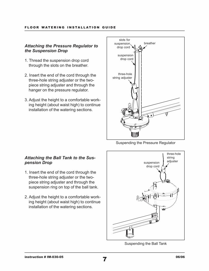
Attaching the Pressure Regulator tothe Suspension Drop
1. Thread the suspension drop cord
through the slots on the breather.
2. Insert the end of the cord through the
three-hole string adjuster or the two-
piece string adjuster and through the
hanger on the pressure regulator.
3. Adjust the height to a comfortable work-
ing height (about waist high) to continue
installation of the watering sections.
Attaching the Ball Tank to the Sus-pension Drop
1. Insert the end of the cord through the
three-hole string adjuster or the two-
piece string adjuster and through the
suspension ring on top of the ball tank.
2. Adjust the height to a comfortable work-
ing height (about waist high) to continue
installation of the watering sections.
Suspending the Ball Tank
suspension
drop cord
three-hole
string
adjuster
suspension
drop cord
three-hole
string adjuster
slots for
suspension
drop cord
breather
Suspending the Pressure Regulator
7

F L O O R W AT E R I N G I N S TA L L AT I O N G U I D E
instruction # IM-030-05 06/06
Installing the WateringSections
Attaching the Suspension Hangers
Before proceding determine the number of
suspension hangers required for this step
of the installation.
Breeders and Pullets:
Attach 5 Suspension Hangers evenly
spaced along the length of the watering
section.
Connecting the Watering Sections
The first watering section has already been
connected to either the pressure regulator
or the ball tank.
1. Suspend the end opposite the regulator
or ball tank and set the height to waist
height.
2. Insert the end of the next watering
section into the expansion connector and
crimp the ring.
3. Connect the aluminum rails with the
metal connector as illustrated and
tighten.
suspension
hanger
metal rail
connector
expansion
connector
Connecting the Watering Sections
Hanger Arrangement for Pullets and Breeders Hanger Arrangement for Broilers
1 hanger near
end of section5 hangers
spaced
evenly
Broilers:
Attach 1 Suspension Hanger close to the
end of the watering section near the ex-
pansion connector.
8

F L O O R W AT E R I N G I N S TA L L AT I O N G U I D E
instruction # IM-030-05 06/06
Cutting the Pipe for the Slope Reducer
3-1/4 inch
[83 mm]
Installing the Slope Re-ducers
Establishing the Slope Reducer Loca-tion
Determine the exact location of the slope
reducer based on the model type being
used. Lubing offers 4 inch, 6 inch and 8
inch slope reducers.
Cutting the Pipe for the Slope Re-ducer
When the location of the slope reducer is
determined cut 3-1/4 inches of pipe using a
pvc cutter to make a clean cut and debur.
9
blue:
red:
black:
4 in [10cm]
6 in [15cm]
8 in [20cm]
Identifying the Slope Compensation Type
Establishing the Slope Reducer Location
slope
compensation

F L O O R W AT E R I N G I N S TA L L AT I O N G U I D E
instruction # IM-030-05 06/06
Installing the Slope Reducer
1. Before installing the slope reducer make
note of the arrow stamped on its side.
This arrow indicates the direction of the
water flow.
2. Apply a small amount of lubrication to
the pvc pipe and insert both pipes into
the slope reducer . Vegetable oil is
recommended as a safe lubricating
agent.
NOTE: Do not use petroleum based
lubricants on pvc.
NOTE: Do not glue this assembly. This
component includes a special inter-
nal seal.
Installing the Mid-LineShut-Off
Cutting the Pipe for the Mid-LineShut-Off Assembly
Determine the location of the mid-line shut-
off assembly and cut 15-1/2 inches of pipe
with a pipe cutter to make a clean cut and
debur.
arrow indicates
water flow direction
Installing the Slope Reducer
Cutting the Pipe for the Mid-Line Shut-Off
Assembly
15-1/2 inch
[394 mm]
10
F L O O R W AT E R I N G I N S TA L L AT I O N G U I D E
instruction # IM-030-05 06/06
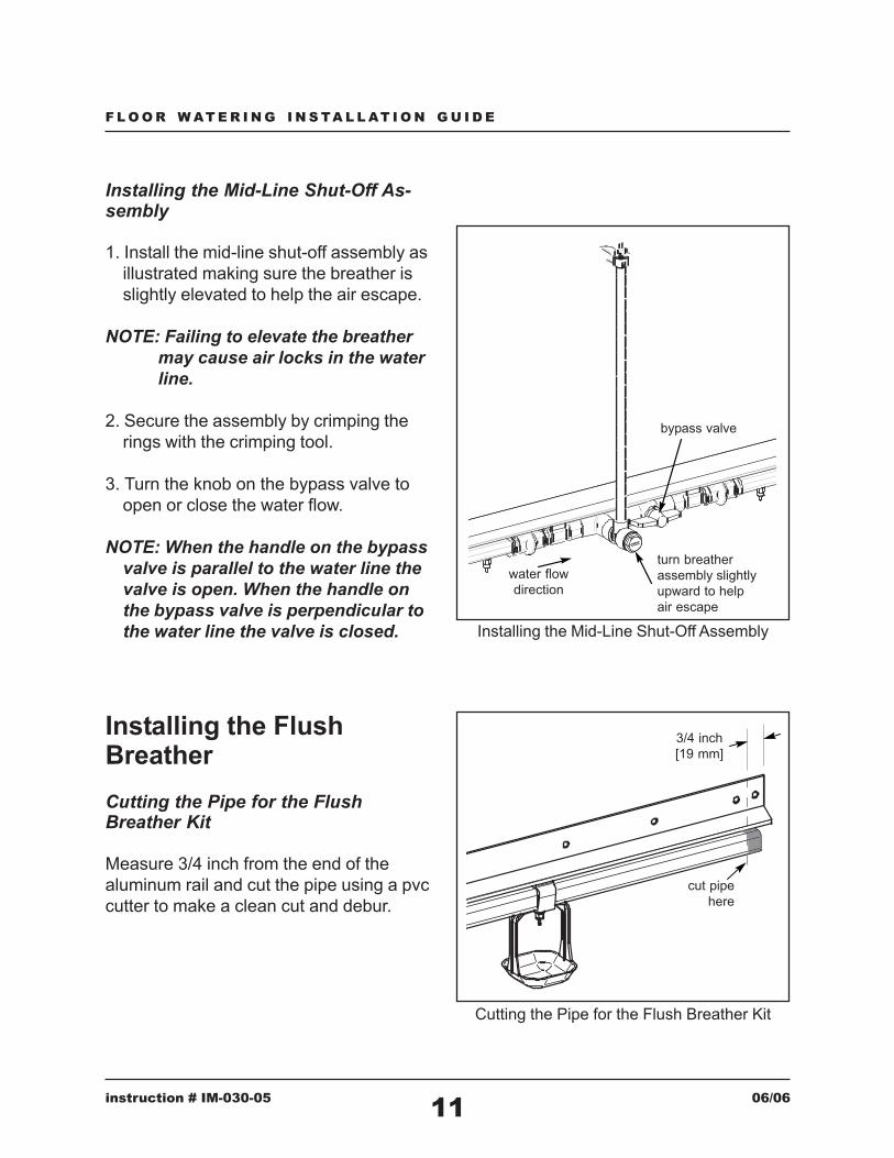
Installing the Mid-Line Shut-Off As-sembly
1. Install the mid-line shut-off assembly as
illustrated making sure the breather is
slightly elevated to help the air escape.
NOTE: Failing to elevate the breather
may cause air locks in the water
line.
2. Secure the assembly by crimping the
rings with the crimping tool.
3. Turn the knob on the bypass valve to
open or close the water flow.
NOTE: When the handle on the bypass
valve is parallel to the water line the
valve is open. When the handle on
the bypass valve is perpendicular to
the water line the valve is closed.
Installing the FlushBreather
Cutting the Pipe for the FlushBreather Kit
Measure 3/4 inch from the end of the
aluminum rail and cut the pipe using a pvc
cutter to make a clean cut and debur.
turn breather
assembly slightly
upward to help
air escape
bypass valve
water flow
direction
Installing the Mid-Line Shut-Off Assembly
cut pipe
here
3/4 inch
[19 mm]
Cutting the Pipe for the Flush Breather Kit
11

F L O O R W AT E R I N G I N S TA L L AT I O N G U I D E
instruction # IM-030-05 06/06
Installing the Flush Breather Kit
1. Apply a small amount of lubrication to
the pvc pipe and insert it into the flush
breather kit approximately 1 inch. Veg-
etable oil is recommended as a safe
lubricating agent.
NOTE: Do not use petroleum based
lubricants on pvc.
NOTE: Do not glue this assembly. This
component includes a special inter-
nal seal.
2. Insert the aluminum rail into the hanger
and align the holes on the aluminum with
the hanger.
4. Bolt the hanger and aluminum rail to-
gether as illustrated.
Installing the ShockerWire
Connecting the Shocker Wire to thePressure Regulator
1. Attach the end of the of the shocker wire
to the three-hole string adjuster.
2. Connect one end of the spring to the
regulator hanger and the other end to
the three-hole string adjuster as illus-
trated.
hanger
1/2 inch
hose barb
3/4 inch
hose barb
Installing the Flush Breather Kit
hanger
shocker
wirespring
three-hole
string adjuster
Connecting the Shocker Wire to the Regulator
12

F L O O R W AT E R I N G I N S TA L L AT I O N G U I D E
instruction # IM-030-05 06/06
Connecting the Shocker Wire to theBall Tank
1. Attach the end of the of the shocker wire
to the three-hole string adjuster.
2. Connect one end of the spring to the ball
tank and the other end to the three-hole
string adjuster as illustrated.
Connecting the Shocker Wire to theFlush Breather
1. Attach one end of the spring to the flush
breather hanger and the other end to
three-hole string adjuster.
2. Thread the end of the shocker wire
through the three-hole string adjuster
and apply tension to the line.
NOTE: Be careful not to stretch the
springs beyond twice their original
length.
shocker
wire
three-hole
string adjuster
spring
shocker
wire
hanger
spring
three-hole
string adjuster
Connecting the Shocker Wire to the Ball Tank
Connecting the Shocker Wire to the Flush
Breather
13

F L O O R W AT E R I N G I N S TA L L AT I O N G U I D E
instruction # IM-030-05 06/06
Installing the Water Pannel
Mounting the Water Pannel
Install the water pannel to the wall using
the mounting brackets provided.
Installing the Header Kit
Connecting the Header Kit to theRegulator or Ball Tank
1. Using the appropriate pvc components
assemble and glue the header kit lead-
ing from the water pannel to the regula-
tors or ball tanks.
2. Make sure that the “T” drop is directly
above the water entry point on the regu-
lator or ball tank.
14
mounting
bracket
NOTE: Water panel configurations may vary.
Medicator not illustrated.
Overall View of Header Kit Installation
header kit
piping
garden
hose
optional
coiled
hose
Mounting the Water Panel
F L O O R W AT E R I N G I N S TA L L AT I O N G U I D E
instruction # IM-030-05 06/06
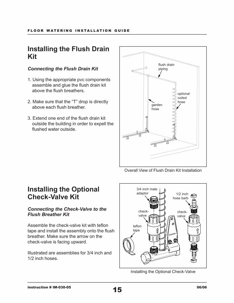
Installing the Flush DrainKit
Connecting the Flush Drain Kit
1. Using the appropriate pvc components
assemble and glue the flush drain kit
above the flush breathers.
2. Make sure that the “T” drop is directly
above each flush breather.
3. Extend one end of the flush drain kit
outside the building in order to expell the
flushed water outside.
15
Overall View of Flush Drain Kit Installation
flush drain
piping
garden
hose
optional
coiled
hose
Installing the OptionalCheck-Valve Kit
Connecting the Check-Valve to theFlush Breather Kit
Assemble the check-valve kit with teflon
tape and install the assembly onto the flush
breather. Make sure the arrow on the
check-valve is facing upward.
Illustrated are assemblies for 3/4 inch and
1/2 inch hoses.
teflon
tape
check-
valve
3/4 inch male
adaptor
check-
valve
1/2 inch
hose barb
Installing the Optional Check-Valve

F L O O R W AT E R I N G I N S TA L L AT I O N G U I D E
instruction # IM-030-05 06/06
Post Installation Proce-dures
When the installation of the system is
completed:
1. Adjust the water lines making sure they
are level and that there are no high and
low spots.
2. Check to make sure that all of the con-
nections between watering sections
have been properly crimped.
3. Check to make sure that all nuts and
bolts have been properly tightened.
4. Check to make sure that all hoses have
been properly clamped.
5. Check to make sure that the filter is in
the water filter shell.
6. Apply water to the entire system and
check for any leaks.
7. Flush the water lines for apporximately
10 minutes to remove potential debris
and air from the system.
16
CAUTION: When cleaning the
water lines with chlorine do not exceed
4 ppm. High levels of chlorine can
cause damage to the watering system.
Please refer to our watering and chemical
reference guide for further details.

AT1 32294425.1
LUBING SYSTEMS, L.P. LIMITED PRODUCT WARRANTY
LIMITED WARRANTY
Each new product provided by Lubing Systems, L.P. (each “Product”) is warranted to be free
from defects in material or workmanship for one (1) year from date of purchase by or for the
original purchaser.
ELIGIBILITY FOR LIMITED WARRANTY
In order to be eligible for coverage under this Limited Warranty, each of the following conditions must be
satisfied:
1. The Product must be installed and operated in accordance with the written
instructions published by the Manufacturer with respect to the product; and
2. The Product must be purchased from and installed by an authorized distributor
and/or certified representative of Lubing Systems, L.P.
SOLE REMEDY
In the event of a covered Warranty claim, Lubing Systems, L.P. will, as the sole remedy and
measure of damages, at its option and in its sole discretion, repair or replace the covered Product
free of charge, F.O.B. its plant in Cleveland Tennessee. Labor and delivery costs associated with
the replacement or repair of the covered Product are not included in or covered by the Warranty.
EXCLUSIONS
1. Malfunctions, failures, or breakage caused by misuse, abuse, negligence,
alteration, accident, chemicals or minerals in the water, poor quality water, lack of sufficient
water, lack of proper maintenance, electrical power surges, interruptions in power, acts of God,
acts of war, riot, terrorism, or civil disobedience shall not be considered defects under the
Warranty, and are excluded from coverage.
2. Alteration of the Product from the manufacturer’s original configuration, and the
installation of additional or replacement components other than original equipment provided and
installed by the manufacturer or Lubing Systems, L.P. shall not be considered defects under the
Warranty, and are excluded from coverage.
3. Use of the Product other than in accordance with the manufacturer’s operational
instructions and guidelines shall not be considered a defect under the Warranty, and any claims
resulting from or attributable to such use are excluded from coverage.
4. The Warranty does not extend to claims made by persons other than the original
consumer purchaser, and are excluded from coverage.

AT1 32294425.1
LIMITATION OF WARRANTY
1. EXCEPT AS PROVIDED ABOVE, LUBING SYSTEMS, L.P. MAKES NO
WARRANTIES OR CLAIMS OF ANY KIND WITH RESPECT TO THE PRODUCTS.
LUBING SYSTEMS, L.P. HEREBY SPECIFICALLY DISCLAIMS ANY IMPLIED
WARRANTY OR CONDITION, WHETHER STATUTORY OR OTHERWISE,
INCLUDING ANY WARRANTY OF MERCHANTABILITY OR FITNESS FOR A
PARTICULAR PURPOSE.
2. LUBING SYSTEMS, L.P. IS NOT RESPONSIBLE FOR LOSS OF TIME
OR PROFITS, INCREASED COSTS OF LABOR, INCONVENIENCE, LOSS OF USE
OF PRODUCT, LOST SALES OR ORDERS, OR ANY OTHER CONSEQUENTIAL,
INCIDENTAL OR INDIRECT DAMAGES.
3. THIS LIMITED WARRANTY IS ONLY APPLICABLE IN THE UNITED
STATES AND CANADA.
4. THIS LIMITED WARRANTY CONSTITUTES THE ENTIRE
WARRANTY GIVEN BY LUBING SYSTEMS, L.P. WITH RESPECT TO THE
PRODUCTS, AND LUBING SYSTEMS, L.P.’S COMPLETE OBLIGATION WITH
RESPECT TO THE PRODUCTS IS STATED IN THIS LIMITED WARRANTY. NO
PERSON OR ENTITY HAS THE AUTHORITY TO IMPLY, SUGGEST, AGREE,
REPRESENT, WARRANT, OR PROMISE CONTRARY TO THE TERMS OF THIS
LIMITED WARRANTY.
WARRANTY CLAIM PROCEDURE
In order to present a claim for coverage under this Limited Warranty, please contact Lubing
Systems, L.P. at:
LUBING Systems, LP
135 Corporate Drive, SW
Cleveland, TN 37311
423-709-1000 tel
423-709-1001 fax
866-289-3237 toll-free fax
When calling, you will be requested to provide the following information:
1. Your name;
2. Your address;
3. Your phone number(s);
4. The date of the Product malfunction or failure;
5. The Product identifier number;
6. Proof of the date of purchase of the covered Products;
7. The invoice number or bill of lading from the delivery of the covered Products; and
8. The nature of the Product defect, malfunction, or failure.

AT1 32156053.3
GENERAL TERMS AND CONDITIONS
Lubing Systems, L.P. (“Lubing”)
Lubing accepts purchase orders, offers and counter-offers from Buyer, and contracts with Buyer, only under the terms and conditions specified herein. Buyer's terms
and conditions in relation to this transaction, except price and quantity, are each specifically objected to by Lubing and shall not apply to this transaction, unless subsequently
agreed in writing signed by an authorized representative of Lubing.
I. Price and Taxes
1. Unless otherwise specifically agreed in writing signed by an authorized representative of Lubing, prices for products (“Products”) are as stated Lubing’s Complete Parts
List, found on Lubing’s website (www.lubingusa.com), and whether for domestic or export shipment, is F.O.B. point of shipment.
2. For additional requirements agreed by Lubing after agreeing to the price, Buyer shall pay Lubing's increases in time, cost or expense for any such change, including
Product characteristics, configurations, form or material, quality levels, special testing, inspection or measurement, special drawings or any other such change or
additional requirement.
3. Any present or future taxes which Lubing may be required to pay or collect with respect to the sale, purchase, delivery, storage, use, consumption or transportation of the
Products, shall be paid by the Buyer.
4. Payment terms for U. S. transactions are net thirty (30) days from the date of shipment of Products to Buyer, unless specifically agreed in writing otherwise. Payment for
export shipments must be by advance payment or by irrevocable letter of credit payable at site in local currency at par, issued and confirmed by banks acceptable to
Lubing, unless other arrangements are specifically agreed in writing.
II. Delivery
1. Products shall be packaged by Lubing's standard method and shipped to the agreed destination via commercial freight carrier as selected by Lubing.
2. Products shall be shipped by Lubing when prepared in the ordinary course of its business. Dates for shipment specified in this contract are targets, but not
commitments, of Lubing unless agreed upon in writing by Lubing.
3. At Buyer's cost and as may be agreeable to Lubing, Buyer may pickup Products at Lubing's facility or specify other means of delivery acceptable to Lubing.
III. Quality and Warranty
1. Lubing warrants Products to be free from defect in material and workmanship only as provided in Lubing’s General Product Warranty as found on Lubing’s website
(www.lubingusa.com), as may be amended, modified, or replaced from time to time.
2. In addition, Lubing warrants Products included on Nipple Selection catalog to be free from defect in material and workmanship only as provided in Lubing’s Nipple
Warranty as found on Lubing’s website (www.lubingusa.com), as may be amended, modified, or replaced from time to time.
3. The foregoing warranties are only valid for Products defective at the time of shipment or for defect in installation performed by Lubing personnel.
4. No warranty shall extend to Products which have been subjected after shipment by Lubing to misuse, neglect, accident, improper installation (other than by Lubing
personnel), or which has been repaired or altered other than by Lubing personnel.
5. THE FOREGOING WARRANTIES ARE IN LIEU OF ALL OTHER WARRANTIES AND REMEDIES FOR PERFORMANCE AND CONDITION OF
THE PRODUCTS AND INSTALLATION, AND EXCEPTING A COVENANT FOR GOOD TITLE TO THE PRODUCTS, LUBING MAKES NO
OTHER WARRANTY, EXPRESSED OR IMPLIED, INCLUDING WARRANTIES OF MERCHANTABILITY, OR OF FITNESS FOR USE FOR A
PARTICULAR PURPOSE.
IV. Claims
1. On notice of warranted defect, Lubing may conduct an on-site investigation.
2. Buyer shall assist in all reasonable ways with Lubing's investigation of claims.
3. All claims of warranty coverage shall be handled in accordance with Lubing’s General Product Warranty as found on Lubing’s website (www.lubingusa.com), as
may be amended, modified, or replaced from time to time.
V. Limitation on Liability
1. The parties agree that the exclusive remedy of Lubing for any claims related to Products installation, performance, or warranty shall be as provided in Lubing’s
General Product Warranty as found on Lubing’s website (www.lubingusa.com), as may be amended, modified, or replaced from time to time.
2. Lubing shall not be liable in any event for any other expense incurred by Buyer or others, nor for any special, consequential, liquidated, incidental, punitive, or other
damages, losses or penalties suffered by Buyer or anyone else with respect to the Products delivered or offered by Lubing, or Lubing's Product installation, including
without limit, loss of profit, production, or use, or damage to other goods or property.
VI. Late Payment and Security Interest
1. Buyer grants to Lubing a purchase money security interest in all Products purchased from Lubing until all amounts owed to Lubing from Buyer are paid, specifically
authorizes Lubing to file such UCC financing statements or other documents as may be required to perfect such security interest, and shall execute any documents
necessary for Lubing to perfect such security interest.

AT1 32156053.3
2. If at any time any payment due to be paid by Buyer to Lubing is past due, Lubing may reschedule, suspend or cancel any pending deliveries to Buyer. If Buyer
voluntarily or involuntarily becomes a debtor in any bankruptcy, insolvency, workout or similar process, then thereafter payment for Products shall be by cash to
Lubing sixty (60) days in advance of delivery to Buyer; Lubing may suspend all work towards completion of Products to be delivered until such payment is made,
and the date for delivery shall be on or before the sixtieth (60th) day following such payment.
3. Buyer grants to Lubing permission to enter Buyer's premises and to obtain possession of any Products with respect to which payment is not made in accordance
herewith.
4. Amounts owed to Lubing from Buyer shall include promises to pay and other commitments to pay which may be in substitution of accounts or other obligations.
VII. Cancellation by Buyer
1. For the period Lubing delays or postpones shipment at Buyer's request or for overdue accounts, Buyer shall pay a delay charge on Lubing's committed costs at an
annual rate of twelve percent (12%).
2. When Lubing has received from Buyer adequate notice in writing prior to commencement of manufacture of the Products, Lubing shall rescind a standing purchase
order, but Buyer shall be responsible for costs incurred by Lubing in preparation of manufacture, including without limitation, cost of raw materials, labor,
engineering, overhead and selling and other expenses.
VIII. Termination and Modification
1. Termination of any purchase order requires the written consent of both parties unless otherwise specifically provided. Lubing may terminate a purchase order unilaterally
for failure to pay when due, and also if Buyer has not made reasonable progress in correcting another material breach of any agreement between Lubing and Buyer within
thirty (30) days after notice thereof.
2. Except for payment of accounts when due, neither party shall be liable for loss, damage, detention or delay resulting from any cause whatsoever beyond its reasonable
control (“Force Majeure”). The party affected by such Force Majeure promptly shall notify the other party. If performance, other than payment when due, is delayed by
Force Majeure for more than thirty (30) days, then either party may terminate this Contract on notice to the other.
3. In the event of termination of a purchase order as provided in subsections 1 or 2, above, Buyer shall make payment to Lubing of the full price for the Products less all net
savings of Lubing, if any, as determined by Lubing to result from such termination.
4. In the event of termination of a purchase order other than as provided in subsections 1 and 2 above, Buyer shall be required to pay to Lubing the full purchase price for the
Products ordered.
IX. Disputes and Interpretation
1. Any dispute between the parties arising out of this Agreement shall be determined by binding arbitration under the rules of the American Arbitration Association
("AAA"). The arbitration shall be conducted in Atlanta, Georgia, by a single arbitrator mutually acceptable to the parties, or, in the event the parties are unable to agree
upon a single arbitrator, by a single arbitrator appointed by the Atlanta, Georgia, office of such association. The cost of the arbitrator and of AAA shall be divided and
borne equally by the parties.
2. The law of the State of Tennessee shall govern the relationship among Lubing and Buyer. These Terms and Conditions are part of any other documents to which these
Terms and Conditions are attached or by which these Terms and Conditions are referenced, and such documents are incorporated herein by this reference and, except as
are specifically objected to by Lubing or by these Terms and Conditions, are a part of the entire agreement among the parties.
3. No waiver by one party of any rights which that party may have shall be considered a waiver of subsequent assertion of such rights, except in accordance with the terms of
a written waiver. Any provision of these Terms and Conditions determined to be unenforceable shall be interpreted in the most limited extent possible so as not to render
the remainder of the provisions of these Terms and Conditions, or any agreement of which these Terms and Conditions are a part, unenforceable.

AT1 32298761.1
Lubing Systems L.P. Returned Goods Policy
December 17, 2005
Returns. Except for Lubing’s Products that are defective at the time of delivery to
Distributor, Lubing shall not be obligated to accept returns of any of Lubing’s Products. Any
permitted returns shall be handled in accordance with Lubing’s Returned Good Policy, as may be
amended from time to time.
1. Distributor shall examine each Product purchased and notify Lubing in writing of
any defective Product within five (5) days following Distributor’s (or Distributor’s customer’s)
receipt of such Product. Products shall be deemed accepted unless Lubing has been notified of
such defect within such five (5) day period.
2. Any item being returned to Lubing must be accompanied by a Returned Goods
Authorization number (an “RGA”), clearly visible on the outside of the return packaging. Any
item received by Lubing without a clearly visible RGA will be returned to sender at sender’s
expense. Distributor (or distributor’s customer) should contact Lubing at (866) 289-3237 to
obtain an RGA, and should have the following information available:
(a) Name of party billed
(b) Shipment destination
(c) Name of grower and integrator (if applicable)
(d) Status of invoice payment
(e) Exact quantity and description of items for return
(f) Reason for return and condition of returned Product
All returns should be shipped freight prepaid.
3. If Lubing issues replacement Product prior to Lubing’s receipt of the returned
Product, then Lubing will issue credit against the invoice for replacement Product upon Lubing’s
receipt of the returned Product.
4. Lubing reserves the right to impose a restocking charge of twenty- percent (20%)
of the purchase price of any returned Product.

AT1 32298808.2
LUBING SYSTEMS, LP
CHANGE ORDER POLICY
Lubing constantly strives to meet our customers’ needs. One of the ways this is achieved is
through effective production planning. In order to plan production efficiently, Lubing Systems
must be able to rely on the accuracy and stability of orders, including exact parts, quantities and
shipment dates, to efficiently manage production and provide customers with the best and most
efficient service.
Lubing recognizes that needs can change, however, and will attempt to accommodate
modifications requested by customers according to the following policies:
• Any customer requesting a change to an accepted purchase order is required to
notify Lubing in writing of such change, including changes regarding product
type, quantity and/or shipment dates, not later than two (2) weeks prior to the
scheduled shipment date.
• Customers are required to submit all change order notifications via fax to
(866) 289-3237, or via email to [email protected].
• Lubing will attempt to accommodate requested changes, but cannot guarantee the
original requested ship date if the customer requests changes in product type or
quantity.
• Unless otherwise agreed in writing signed by an authorized Lubing representative,
any change to or cancellation of an accepted purchase order received by Lubing s
upon fewer than two (2) weeks’ notice prior to the scheduled shipment date will
result in a change order fee equal to equal to the purchase price of the subject
Products.
A Tradition of Innovation.
IM-030-05 06/06
LUBING Systems, L.P.
135 Corporate Drive, SW
Cleveland, TN 37311 • USA
423 709.1000 tel
866 289.3237 toll-free fax
www.lubingusa.com
Printed in the U.S.A.
Contact your local Lubing
distributor or representative for
additional information regarding
Lubing products.
All technical content in this
instruction is subject to change.