Floor jack transmission adapter - Harbor Freight...
12
FLOOR JACK TRANSMISSION ADAPTER 39152 SET UP AND OPERATING INSTRUCTIONS Visit our website at: http://www.harborfreight.com Read this material before using this product. Failure to do so can result in serious injury. SAVE THIS MANUAL. Copyright © 2002, 2009 by Harbor Freight Tools ® . All rights reserved. No portion of this manual or any artwork contained herein may be reproduced in any shape or form without the express written consent of Harbor Freight Tools. Diagrams within this manual may not be drawn proportionally. Due to continuing improvements, actual product may differ slightly from the product described herein. Tools required for assembly and service may not be included. For technical questions or replacement parts, please call 1-800-444-3353. Revised Manual 09k
Transcript of Floor jack transmission adapter - Harbor Freight...

Floor jack transmission adapter
39152set up and operating instructions
Visit our website at: http://www.harborfreight.com
read this material before using this product. Failure to do so can result in serious injury. saVe this manual.
Copyright© 2002, 2009 by Harbor Freight Tools®. All rights reserved. No portion of this manual or any artwork contained herein may be reproduced in any shape or form without the express written consent of Harbor Freight Tools. Diagrams within this manual may not be drawn proportionally. Due to continuing improvements, actual product may differ slightly from the product described herein. Tools required for assembly and service may not be included.
For technical questions or replacement parts, please call 1-800-444-3353.Revised Manual 09k
Page 2For technical questions, please call 1-800-444-3353.SKU 39152
saVe this manualKeep this manual for the safety
warnings and precautions, assembly, operating, inspection, maintenance and cleaning procedures. Write the product’s serial number in the back of the manual near the assembly diagram (or month and year of purchase if product has no number). Keep this manual and the receipt in a safe and dry place for future reference.
safety alert symbol and signal Words
in this manual, on the labeling, and all other information provided with this product:
this is the safety alert symbol. it is used to alert you to potential personal injury hazards. obey all safety messages that follow this symbol to avoid possible injury or death.
danger indicates a hazardous
situation which, if not avoided, will result in death or serious injury.
Warning indicates a
hazardous situation which, if not avoided, could result in death or serious injury.
caution, used with the safety
alert symbol, indicates a hazardous situation which, if not avoided, could result in minor or moderate injury.
notice is used to address practices
not related to personal injury.
caution, without the safety alert
symbol, is used to address practices not related to personal injury.
important saFetY instructions
instructions pertaining to a risk oF Fire,
electric shock, or injurY to persons
Warning – When using tools, basic precautions should always be followed, including the following:
generalto reduce the risks of electric a. shock, fire, and injury to persons, read all the instructions before using the tool.
Work areakeep the work area clean and well a. lighted. Cluttered benches and dark areas increase the risks of electric shock, fire, and injury to persons.
Keep bystanders, children, and b. visitors away while operating the tool. Distractions are able to result in the loss of control of the tool.
personal safetyStay alert. Watch what you are a. doing and use common sense

Page 3For technical questions, please call 1-800-444-3353.SKU 39152
when operating the tool. Do not use the tool while tired or under the influence of drugs, alcohol, or medication. A moment of inattention while operating the tool increases the risk of injury to persons.
dress properly. do not wear loose b. clothing or jewelry. contain long hair. keep hair, clothing, and gloves away from moving parts. Loose clothes, jewelry, or long hair increases the risk of injury to persons as a result of being caught in moving parts.
do not overreach. keep proper c. footing and balance at all times. Proper footing and balance enables better control of the tool in unexpected situations.
d. use safety equipment. A dust mask, non-skid safety shoes and a hard hat must be used for the applicable
conditions. Wear heavy-duty work gloves during use.
e. always wear eye protection. Wear ANSI-approved safety goggles.
tool use and caredo not force the tool.a. Use the correct tool for the application. The correct tool will do the job better and safer at the rate for which the tool is designed.
Store the tool when it is idle out b. of reach of children and other untrained persons. A tool is dangerous in the hands of untrained users.
maintain the tool with care. c. Keep a cutting tool sharp and clean. A properly maintained tool, with sharp cutting edges reduces the risk of binding and is easier to control.
check for misalignment or binding d. of moving parts, breakage of parts, and any other condition that affects the tool’s operation. If damaged, have the tool serviced before using. Many accidents are caused by poorly maintained tools. There is a risk of bursting if the tool is damaged.
use only accessories that are e. identified by the manufacturer for the specific tool model. Use of an accessory not intended for use with the specific tool model, increases the risk of injury to persons.
serviceTool service must be performed a. only by qualified repair personnel.
When servicing a tool, use only b. identical replacement parts. use only authorized parts.
saVe these instructions.

Page 4For technical questions, please call 1-800-444-3353.SKU 39152
sYmbols and speciFic saFetY
instructionsSymbol Definitions
symbol property or statement
no No-load speed
.../min Revolutions or reciprocation per minute
psi Pounds per square inch of pressure
ft-lb Foot-pounds of torque
bpm Blows per minute
cFm Cubic Feet per Minute flow
scFm Cubic Feet per Minute flow at standard conditions
npt National pipe thread, tapered
nps National pipe thread, straight
WARNING marking concerning Risk of Eye Injury. Wear ANSI-approved eye protection.WARNING marking concerning Risk of Hearing Loss. Wear hearing protection.WARNING marking concerning Risk of Respiratory Injury. Wear NIOSH-approved dust mask/respirator.
WARNING marking concerning Risk of Explosion.
Specific Safety Instructionsdo not exceed 880 lb. weight 1. capacity evenly distributed. be aware of dynamic loading! Sudden load movement may briefly create excess load causing product failure. exceeding the maximum capacity
for this product is dangerous and can lead to serious injury or property damage.
if in doubt about the safety of 2. your project, have the work done by a professional familiar with applicable safe practices.
Use only with 2-1/4 Ton Floor Jack 3. (such as SKU 50183 Heavyweight Floor Jack, sold separately).
Always evaluate your task before 4. using this Adapter. This adapter is designed to support a transmission or a differential as individual components. Use as intended only. Do not use for aircraft purposes.
Assemblies such as differential 5. with axle, or transmission with bell housing, can be bulky and difficult to balance on the Base (38). lifting or supporting such assemblies, even within weight limit, can create an off-balance situation, causing adapter and/or jack to tip over and maY lead to serious personal injury or property damage.
The load should be evenly distributed 6. on the jack, and should not extend beyond the area of the castor wheelbase. Always use the Chain (5) to secure the load. If extra support is required, safety straps (not included) can also be used to secure the workpiece.
If you are working and the load 7. becomes off-balance and/or the jack begins to tip over, do not attempt to catch or liFt the load When Falling. serious personal injurY can result! In this event, clear the area as

Page 5For technical questions, please call 1-800-444-3353.SKU 39152
quickly and safely as possible in order to avoid injury from the falling load, including getting hit with flying fragments.
If in doubt about the safety of your 8. project, we advise you to have the work done by a professional familiar with applicable safety practices.
Use only on a hard, level and flat 9. surface capable of bearing the combined weight of the Adapter and Jack, the car being lifted, the operator and any tools being used.
The Adapter is not designed to lift or 10. lower a vehicle. Suspend the vehicle with an in-floor hydraulic jack (not included) or four jack stands or any lifting device designed to raise and support weight of vehicle.
The warnings and precautions 11. discussed in this manual cannot cover all possible conditions and situations that may occur. It must be understood by the operator that common sense and caution are factors which cannot be built into this product, but must be supplied by the operator.
saVe these instructions.
Functional description
Specifications
Weight Capacity 880 lb.
Base Tilt 60° Forward 10° Backwards
Saddle Pin Diameter .094” For Use Only With 2-1/4 Ton Transmission Jack
(SKU 50183 Heavyweight Floor Jack)
initial tool set up/assemblY
read the entire important saFetY inFormation section at the beginning of this manual including all text under subheadings therein before set up or use of this product.
note: For additional information regarding the parts listed in the following pages, refer to the Assembly Diagram near the end of this manual.
unpackingWhen unpacking, make sure that the
item is intact and undamaged. If any parts are missing or broken, please call Harbor Freight Tools at 1-800-444-3353 as soon as possible.
assemblYnote:1. The Base (38) of the Transmission Adapter is preassembled. Only the Adjustable Steel Angles (6) need to to be attached to the Base. Some other minor assembly steps are required, as follows.
Page 6For technical questions, please call 1-800-444-3353.SKU 39152
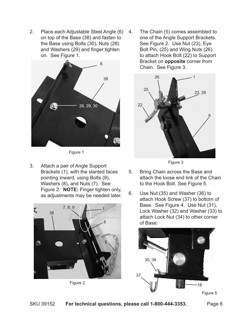
Place each Adjustable Steel Angle (6)2. on top of the Base (38) and fasten to the Base using Bolts (30), Nuts (28) and Washers (29) and finger tighten on. See Figure 1.
Attach a pair of Angle Support 3. Brackets (1), with the slanted faces pointing inward, using Bolts (9), Washers (8), and Nuts (7). See Figure 2. note: Finger tighten only, as adjustments may be needed later.
The Chain (5) comes assembled to 4. one of the Angle Support Brackets. See Figure 2. Use Nut (23), Eye Bolt Pin, (25) and Wing Nuts (26) to attach Hook Bolt (22) to Support Bracket on opposite corner from Chain. See Figure 3.
Bring Chain across the Base and 5. attach the loose end link of the Chain to the Hook Bolt. See Figure 5.
Use Nut (35) and Washer (36) to 6. attach Hook Screw (37) to bottom of Base. See Figure 4. Use Nut (31), Lock Washer (32) and Washer (33) to attach Lock Nut (34) to other corner of Base.
Figure 1
Figure 2
Figure 3
6
38
28, 29, 30
381
6
7, 8, 9
5
22
6
1
2523, 26
26
Figure 5
37
35, 36
18

Page 7For technical questions, please call 1-800-444-3353.SKU 39152
The bottom of the Base Shaft (18) is 7. then securely placed into the saddle of the Transmission Jack to firmly hold the Transmission Adapter in place. See Figure 5.
operating instructions read the entire important
saFetY inFormation section at the beginning of this manual including all text under subheadings therein before set up or use of this product.
inspect tool before use, looking for damaged, loose, and missing parts. if any problems are found, do not use tool until repaired.
tool set up to preVent
serious injurY From accidental operation: remove load and lower transmission jack before performing any inspection, maintenance, or cleaning procedures.
to preVent serious injurY: do not adjust or tamper with any control or component in a way not specifically explained within this manual. improper adjustment can result in tool failure or other serious hazards.
general operating instructions Warning! Verify that Floor Jack is
compatible with this Transmission Jack Adapter before operation.
Designate a work area that is clean 1. and well-lit. The work area must not allow access by children or pets to prevent distraction and injury.
Raise the vehicle at least as high 2. as the combined height of your transmission and the lowered height of the Transmission Jack.
When the vehicle is safely raised on 3. Jack Stands, set the Transmission Adapter underneath the vehicle. Position the Floor Jack with the Transmission Adapter attached so that the pairs of Angle Irons will hold the forward and rear ends of the transmission.
With the vehicle safely supported on 4. jack stands, set the Transmission Adapter underneath the transmission. Pump the handle and raise the unit until the transmission just makes contact with the Adapter. Slide the two Adjustable Steel Angles (6) and four Support Brackets (1) over the transmission. Turn the Tilt adjustment Knob (10) so that the adapter base rests flat against the bottom of the transmission. Turning the Knob clockwise will lower (pull down) the opposite end of the base. Turning the Knob counterclockwise will raise it.
Tighten the bolts and screws to 5. support the transmission with the Brackets
Place the Chain over the 6. transmission and snap it to the Hook

Page 8For technical questions, please call 1-800-444-3353.SKU 39152
Bolt (22). Turn the nut to retract the bolt and hold the transmission snugly.
Follow the steps in your vehicle’s 7. Owner’s Service Manual, remove drive shaft and any and all mounting bolts and/or nuts.
Depending on type of transmission, 8. you may need to move Jack and transmission back a few inches to free input shaft of the transmission.
Prior to moving the transmission, 9. double-check that it is secured to the Transmission Adapter.
Warning! 10. Transmission is heavy and prone to rocking during lowering procedure. Use caution when lowering it to prevent accidental rocking of it.
transmission installation
Verify that the vehicle is properly and 1. safely raised on the Jack Stands.
Warning!2. Do not work under a car supported by jacks, or jack stands individually rated less than the total weight of the vehicle.
Verify that you have all of the 3. necessary hardware and supplies to install the transmission. Do not leave the transmission suspended by the Floor Jack if you need to obtain additional supplies.
Check to make sure the Chain is 4. tightly holding the transmission. Readjust the Chain if needed.
Roll the Floor Jack under the vehicle. 5. Place it so that the transmission
centerline is as close to the centerline of the engine as possible.
Begin raising the transmission. 6. Continue raising it until it is at the installation height.
With the transmission at the correct 7. height in the transmission tunnel of the vehicle, adjust the attitude of the transmission if needed.
Warning!8. Do not attempt to adjust the position of the transmission manually. Adjust using ONLY the methods described.
If you are working and load becomes 9. off-balance and/or jack begins to tip DO NOT ATTEMPT TO CATCH OR LIFT WHEN FALLINg. SERIOUS PERSONAL INJURY CAN bE SUFFERED! In this event, clear area as quickly and safely as possible in order to avoid injury from falling load or flying fragments. IF IN DOUbT AbOUT THE SAFETY OF YOUR PROJECT, WE ADvISE YOU TO HAvE THE WORk DONE bY A PROFESSIONAL FAMILIAR WITH APPLICABLE SAFE PRACTICES.
Remove Chain from around 10. transmission. Install transmission into the vehicle.

Page 9For technical questions, please call 1-800-444-3353.SKU 39152
inspection, maintenance, and cleaning
Procedures not specifically explained in this manual must be performed only by a qualified technician.
to preVent serious injurY
From tool Failure: do not use damaged equipment. if abnormal noise or vibration occurs, have the problem corrected before further use.
Warning! remove any load from 1. the adapter before performing any inspection, maintenance or cleaning procedures.
before each use, 2. inspect the general condition of the Transmission Jack. Check for oil leaks, jack operation, loose components, free rotation and pivoting of saddle adjustment components. If a problem occurs, have the problem corrected before further use. do not use damaged equipment.
periodically, lubricate all pivot 3. points.
To clean, use a mild detergent and 4. then dry.
caution! 5. All maintenance, service or repairs not mentioned in this manual must only be performed by a qualified service technician.
record product’s serial number here: note: If product has no serial number, record month and year of purchase instead.
note: Some parts are listed and shown for illustration purposes only, and are not available individually as replacement parts.

Page 10For technical questions, please call 1-800-444-3353.SKU 39152
part description Q’ty1 Angle Support Bracket 42 Nut (M8) 13 Washer (8) 14 Bolt (M8 x 25) 15 Chain 16 Adjustable Steel Angle 27 Nut (M10) 48 Washer (10) 49 Bolt (M10 x 25) 4
10 Knob 111 Pin (4 x 28) 112 Long Bolt 113 Lift Platform 114 Lock Nut 315 Ring (30) 516 Handle Shaft 117 Bolt (M6 x 8) 318 Base Shaft 119 Ring (16) 2
part description Q’ty20 Axle Sleeve 221 Bracket Shaft 122 Hook Bolt 123 Nut (M10) 124 Washer (10) 125 Eye Bolt Pin 126 Wing Nut (M6) 127 Bracket Assembly 128 Nut (M12) 229 Washer (M12) 430 Bolt (M12 x 30) 231 Nut (M10) 132 Lock Washer (10) 133 Washer (10) 134 Lock Nut Assembly 135 Nut (M8) 236 Washer (8) 237 Hook Screw 138 Base 1
please read the FolloWing careFullYTHE MANUFACTURER AND/OR DISTRIbUTOR HAS PROvIDED THE PARTS LIST AND ASSEMbLY DIAgRAM IN THIS MANUAL AS A REFERENCE TOOL ONLY. NEITHER THE MANUFACTURER OR DISTRIbUTOR MAkES ANY REPRESENTATION OR WARRANTY OF ANY kIND TO THE bUYER THAT HE OR SHE IS qUALIFIED TO MAkE ANY REPAIRS TO THE PRODUCT, OR THAT HE OR SHE IS qUALIFIED TO REPLACE ANY PARTS OF THE PRODUCT. IN FACT, THE MANUFACTURER AND/OR DISTRIbUTOR ExPRESSLY STATES THAT ALL REPAIRS AND PARTS REPLACEMENTS SHOULD bE UNDERTAkEN bY CERTIFIED AND LICENSED TECHNICIANS, AND NOT bY THE bUYER. THE bUYER ASSUMES ALL RISk AND LIAbILITY ARISINg OUT OF HIS OR HER REPAIRS TO THE ORIgINAL PRODUCT OR REPLACEMENT PARTS THERETO, OR ARISINg OUT OF HIS OR HER INSTALLATION OF REPLACEMENT PARTS THERETO.
parts list

Page 11For technical questions, please call 1-800-444-3353.SKU 39152
assemblY diagram
12, 3, 4
5 6
7, 8, 9
101112
1314
1516
17
18192021
38
22
23, 22, 25
26
27
28, 29, 30
31, 32, 33, 34 35, 36, 37

Page 12For technical questions, please call 1-800-444-3353.SKU 39152
limited 90 daY WarrantYHarbor Freight Tools Co. makes every effort to assure that its products meet high
quality and durability standards, and warrants to the original purchaser that this product is free from defects in materials and workmanship for the period of 90 days from the date of purchase. This warranty does not apply to damage due directly or indirectly, to misuse, abuse, negligence or accidents, repairs or alterations outside our facilities, criminal activity, improper installation, normal wear and tear, or to lack of maintenance. We shall in no event be liable for death, injuries to persons or property, or for incidental, contingent, special or consequential damages arising from the use of our product. Some states do not allow the exclusion or limitation of incidental or consequential damages, so the above limitation of exclusion may not apply to you. THIS WARRANTY IS ExPRESSLY IN LIEU OF ALL OTHER WARRANTIES, ExPRESS OR IMPLIED, INCLUDINg THE WARRANTIES OF MERCHANTAbILITY AND FITNESS.
To take advantage of this warranty, the product or part must be returned to us with transportation charges prepaid. Proof of purchase date and an explanation of the complaint must accompany the merchandise. If our inspection verifies the defect, we will either repair or replace the product at our election or we may elect to refund the purchase price if we cannot readily and quickly provide you with a replacement. We will return repaired products at our expense, but if we determine there is no defect, or that the defect resulted from causes not within the scope of our warranty, then you must bear the cost of returning the product.
This warranty gives you specific legal rights and you may also have other rights which vary from state to state.
3491 Mission Oaks Blvd. • PO Box 6009 • Camarillo, CA 93011 • (800) 444-3353