
Floating-Point Test-Suite for IEEE - IBM Research Test-Suite for IEEE IBM Labs in Haifa FPgen Team...
43
Document Name Introduction • 1 Floating-Point Test-Suite for IEEE IBM Labs in Haifa FPgen Team Version 1.02: January 2008
Transcript of Floating-Point Test-Suite for IEEE - IBM Research Test-Suite for IEEE IBM Labs in Haifa FPgen Team...

Document Name Introduction • 1
Floating-Point Test-Suite for IEEE
IBM Labs in Haifa
FPgen Team
Version 1.02: January 2008

Notices First version (June 2004) For information, contact Merav Aharoni. International Business Machines Corporation provides this publication “as is” without warranty of any kind, either express or implied. Some states do not allow disclaimer of express or implied warranties in certain transactions; therefore this statement may not apply to you. This publication may contain technical inaccuracies or typographical errors. While every precaution has been taken in the preparation of this document, the publisher and author assume no responsibility for errors or omissions. Nor is any liability assumed for damages resulting from the use of the information contained herein. Changes are periodically made to the information herein; these changes will be incorporated in new editions of the publication. IBM may make improvements and/ or changes in the product(s) and/or the program(s) described in this publication at any time. IBM may have patents or pending patent applications covering subject matter in this document. The furnishing of this document does not give you any license to these patents. You can send license inquiries, in writing, to the IBM Director of Commercial Relations, IBM Corporation. The following terms, used in this publication, are trademarks or service marks of corporations in the United States or other countries:
IBM IBM Corporation
Change History
Version Author Date Change Description
0 Merav Aharoni 02/28/04 Initial version for binary floating-point
0.9 Merav Aharoni 06/13/04 1. Added decimal test-suite 2. Removed model “All Exponents” 3. Renumbered the models 4. Added rounding mode “ ^ ” 5. Minor syntax corrections
0.91 Sigal Asaf 07/29/04 Adding details to chapter 4 – Syntax of the Test Cases
0.93 Raviv Nagel 12/6/04 Many changes in the binary models. Some overlapping models fixed. Some models were reduced to a more reasonable size. Added Round-To-Integral models
0.94 Merav Aharoni 02/23/05 Renamed model B6 to Tiny Rounding Intermediate Tasks, and removed the overflow tasks from it. B20 was simplified to constrain only the intermediate result. Updated syntax of examples
1.0 Merav Aharoni
Raviv Nagel
04/20/05
05/03/05
First official version posted to test case web site B20 – changed name and simplified model Removed unnecessary chapters at the end

Document Name Introduction • 3
1.01 Merav Aharoni 04/24/05 Updated chapter 4 – Syntax of the Test Cases
1.02 Anatoly Koyfman 01/24/08 Updated chapter 4 – Syntax of the Test Cases
Copyright IBM Corporation 2004. All rights reserved..

Contents
Introduction 6 Overview............................................................................................................................. 6
Methodology 7
Terminology Used in Model Descriptions 9
Syntax of the Test Cases 12
Binary Models 15 Operation-general Models ................................................................................................ 16 Models for Add and Subtract ............................................................................................ 19 Models for Fused Multiply Add........................................................................................ 20 Models for Compare, Min, Max ....................................................................................... 21 Models for Square-Root, Divide, Remainder ................................................................... 22 Models for Convert Float to Integer Operations ............................................................... 23 Models for Convert Integer to Float Operations ............................................................... 24 Models for Conversion between Different FP Formats .................................................... 24 Models for Rounding Float to Integral Value ................................................................... 25
Decimal Terminology 26 Decimal Mask..................................................................................................... 26 Decimal Floating Point Format .......................................................................... 26 Adjusted Exponent ............................................................................................. 27 Decimal Encoded Format ................................................................................... 27 Significant Digits ................................................................................................ 27 Preferred Exponent ............................................................................................. 27 Cancellation Value ............................................................................................. 28
Decimal Floating-Point Types .......................................................................................... 28
Decimal Models 29 Operation-general Models ................................................................................................ 32 Models for Add and Subtract ............................................................................................ 36 Models for Multiply.......................................................................................................... 38 Models for Fused Multiply Add........................................................................................ 38
Multiply-Add: Interesting Events ....................................................................... 39

Document Name Introduction • 5
Models for Compare, Min, Max ....................................................................................... 40 Models for Square-Root, Divide, Remainder ................................................................... 41 DPD Models ..................................................................................................................... 42

Chapter 1
Introduction
Overview
This document contains a detailed description of a proposed test-suite for floating-point, conforming to the IEEE 754R standard. This document includes an explanation of the approach taken, a proposed syntax for the test files, and a detailed list of models for binary floating-point and decimal floating-point. Finally we will send the test-suites themselves for both binary and decimal. We welcome all suggestions, as well as comments and questions.
The test-suite will contain tests that target basic formats specified in the IEEE 754R standard. These include binary32, binary64, binary128, decimal32, decimal64, and decimal128. We will supply test-cases for the following operations: add, subtract, multiply, divide, fused multiply-add, square root, remainder, compare, min, max, round to integer, convert float to float, convert float to integer, convert integer to float, and convert and round float to integral value.
Regarding the arithmetic operations, we currently plan to support only the operations for which all operands have the same format.
The structure of this document is as follows: in chapter 2 we explain the methodology used in constructing the test-suite; in chapter 3 we define terms that will be used in the model descriptions; the syntax of the test files is described in chapter 4; chapter 5 contains a description of the binary models; chapters 6 and 7 contain a description of the decimal models, appendix 8 defines a schedule for completion of the remaining components of the test-suite; and appendix 9 lists some open issues.
We view this document as a draft version. We still intend to augment and modify the proposal models. The purpose of this draft is to present a broad impression of the scope of the test-suite, and to provide an opportunity for feedback.
Chapter 2

Document Name Methodology • 7
Methodology
The approach taken in the construction of this test-suite is to first define a high level test-plan, and then to generate a suite of test-cases that cover the test plan. The test plan is created by identifying subspaces that are interesting in terms of verification. These subspaces are defined as verification tasks. We group together sets of related tasks into coverage models. When we say ‘related tasks’, we mean that a model is not simply an arbitrary grouping of the tasks, but rather a set of tasks that target a certain floating-point area, or some particular feature of floating-point.
Having defined the models, we proceed to provide, for each of these tasks, a test-case that covers this task; in other words, a test case is a member of the subspace we wish to test. The test suite comprises a set of files that correspond to coverage models described in this document. Every test case in these files covers a task of the model. The test cases are generated by use of a random test generator, FPgen. More information concerning FPgen can be found in [1] and in http://www.haifa.il.ibm.com/projects/verification/fpgen/
Note that models will often contain tasks for which no test-case can be generated. Therefore, in general, the number of test-cases in a test file may be less than the number of defined tasks. For example, in the model (B1) Floating-point basic types, the addition of two positive Norm inputs cannot result in a negative Norm result. The reason for leaving these tasks in the definition of the model is that this allows describing them in a concise and general manner. Many of the models are defined using the Cartesian product between two or more lists of constraints. This manner of expression is very clear and compact, but may contain impossible combinations.
In addition, there are cases where different models have one or more tasks in common. We prefer not to remove such redundant tasks, in order to maintain the completeness of each model, and the independence of one model from another.
The models are partitioned into two categories:
§ Operation-general models – These models are not dependent on operation semantics, and are therefore applicable to all floating-point operations.
§ Operation-specific models – Each of these models is suitable for one or more specific floating-point operations, and targets special features of the operation semantics.
Every test case specifies values for the rounding mode, the enable bits, and the operands. The test cases are given in all the rounding modes specified by the standard. For models in which

the rounding mode is not significant, we provide test-cases in one randomly selected rounding mode. For models in which we deem the rounding mode significant, test-cases in all rounding modes will be provided.
The enable bits, as defined in the standard, are: inexact result, underflow, overflow, divide by zero, and invalid operation. Each enabled flag may take on the values ON and OFF. For models in which the enable bits are not significant, we provide test-cases in either of the two values, selected at random for each enable bit.

Document Name Terminology Used in Model Descriptions • 9
Chapter 3
Terminology Used in Model Descriptions
In this chapter, we define the terms that will be used when describing the coverage models.
Final result. The final result is the output of the operation, following rounding.
Intermediate result. The standard requires every operation to be performed “as if it first produced an intermediate result correct to infinite precision and with unbounded range, and then rounded that result according to one of the modes”. In order to cope with this requirement, we use an intermediate result with an extended range for the exponent, and extra precision for the significand.
For binary, we extend the significand to include one additional regular bit, named the guard bit, and one sticky bit which is one if and only if there were non-zero bits to the right of the guard bit.
For decimal, as for binary, we add one additional digit to the significand, named the guard digit, and the sticky bit, which is one if and only if there were non-zero digits to the right of the guard digit. Beside these, we add one additional bit, named the rounded bit. This bit is one if and only if there were any digits (including zeros), to the right of, and including, the guard bit. Thus, if the guard digit is non-zero, or the sticky bit is one then the rounded bit is one. But even if both the guard and sticky are zeros, the rounded bit will be one if there was a zero calculated for any of those positions.
The binary models described in this document assume the intermediate result is in normalized format. The decimal models assume the decimal point is positioned to the left of the guard digit.
Extra bits. The Extra Bits for binary floating–point are defined as all the bits that participate in the calculation of the sticky bit. The length of Extra Bits varies between different formats and different operations. For some arithmetic operations this number is finite, and for others it is infinite. For the latter, we use a reasonable number of bits for constraint purposes.

Extra digits. For decimal floating point the definition is similar, the only difference being that the word “bits” is replaced by “digits.
Ulp or Unit in the last place. Ulp is defined as the value of a 1 in the last place of a number representation (Boston University, Computer Science Faculty). For the binary floating-point number b0.b1b2…bk * 2m, ulp = 1 * 2m-k.
For the decimal floating-point number d1d2…dk * 10m, ulp = 1 * 10m .
Shift. Shift is the difference between the unbiased exponents of the input operands in add/subtract operations. In order to perform the operation, one of the operands is shifted so that both operands have the same exponent. This term applies also to the fused multiply-add type operation, with regard to the exponents of the addends.
Cancellation. Cancellation describes a situation that occurs in add/subtract operations, whereby the exponent of the result is lower than either of the exponents of the inputs. This occurs when the inputs are relatively close in magnitude. This term applies also to fused multiply-add operation, with regard to the exponents of the addends.
Binary Mask. A mask is a character representation used to denote a set of binary numbers. Each character of the mask belongs to the set {0, 1, x}, where x means this bit position may take on the values 0 or 1.
For example, the mask 0x111x represents the set {001110, 001111, 011110, 011111}.
Decimal Mask. See chapter 6 "Decimal Terminology".
Precision. We will use the definition from the IEEE 754R. We will denote the precision of a binary or decimal floating-point number by p.
Binary floating-point types
Name Sign Exponent Significand
Zero 0 000…000 000…000
MinSubNorm 0 000…000 000…001
SubNorm 0 000…000 [000…001, 111…111]
MaxSubNorm 0 000…000 111…111
MinNorm 0 000…001 000…000
Norm 0 [000…001, 111…110]
xxx…xxx
MaxNorm 0 111…110 111…111
Infinity 0 111…111 000…000
DefaultNaN 0 111…111 100…000
QNaN X 111…111 1xx…xxx
SNaN X 111…111 [000…001, 011…111]

Document Name Terminology Used in Model Descriptions • 11
011…111]
One 0 011…111 000…000
Table 1: Binary Floating-Point Types
Note that all the basic types are defined to be positive. In the models, we usually have tests for both the positive and negative basic types.
Decimal floating-point types. See chapter 6 "Decimal Terminology".
Chapter 4
Syntax of the Test Cases
Every coverage model has one or more corresponding test files. The names of the files correspond to the names of the models, with the suffix .fptest.
Each test case appears on a separate line that contains, in the order given below:
§ The operation: one of the following: + for add, - for subtract, * for multiply, / for divide, *+ for fused multiply-add, V for square root, % for remainder, rfi for round float to int, cff for convert between different supported floating-point format, cfi for convert floating-point to integer, cif for convert integer to floating-point, cfd for convert to decimal character string, cdf for convert decimal character string to float, qC for quiet comparison, sC for signaling comparison, cp for copy, ~ for negate, A for abs, @ for copy sign, S for scalb, L for logb, Na for nextafter, ? for class, ?- for issigned, ?n for isnormal, ?f for isfinite, ?0 for iszero, ?s for issubnormal, ?i for is inf, ?N for isnan, ?sN for issignaling, ?N for isnan, <C for minnum, >C for maxnum, <A for minnummag, >A for maxnummag, =quant for samequantum, quant for quantize, Nu for next up, Nd for nextdown, eq for equivalent.
§ The rounding mode: one of the following: > (positive infinity), < (negative infinity), 0 (zero), =0 (nearest, ties to even), or =^ (nearest, ties away from zero). The “nearest, ties away from zero” rounding mode exists only for decimal operations only.
§ Trapped exceptions: x (inexact/XE), u (underflow/UE), o (overflow/OE), z (division by zero/ZE) and i (invalid/VE).
§ The data for input operands. See Input and Output Operand Representation below for more information about the data representation.
§ A “->” sign, to separate inputs from results.
§ The data for the outputs. See Input and Output Operand Representation below for more information about the data representation. In case no output is written, a # sign will appear in place of the output data. This

Document Name Syntax of the Test Cases • 13
may occur in the case the invalid exception is enabled and an invalid operation occurred.
§ Exceptions that occur following the operation: x (inexact), u/v/w (underflow), o (overflow), z (division by zero) and i (invalid). There are three flags for underflow since the standard permits an implementation to use any one of three different definitions of underflow: u indicates underflow due to tininess and "extraordinary" error, v indicates underflow due to tininess and inexactness where tininess is tested after rounding, and w indicates underflow due to tininess and inexactness, where tininess is tested before rounding. The enable bits are concatenated to one string.
Input and Output Operand Representation
The following describes the supported operand types. For each type, we describe its representation in the test-suite.
Data type Representation
Binary Floating-Point <sign><significand>P<exp>. Where the sign is either + or -, the significand is a string of hex literals, exp is the value of the unbiased exponent written as an integer number.
SNaN numbers are represented using the string S.
QNaN numbers are represented using the string Q.
Infinities are represented using the string <sign>Inf.
Zeros are represented using the string <sign>Zero.
Decimal Floating-Point
<sign><significand>E<exp>. Where the sign is either + or -, the significand is a string of decimal digits, exp is the value of the unbiased exponent written as an integer number.
SNaN numbers are represented using the string S.
QNaN numbers are represented using the string Q.
Infinities are represented using the string <sign>Inf.
DPD format Some of the decimal floating-point data are represented using their DPD encoding as follows: DPD_<hex string>.
Integer <sign><decimal-digits> where sign is either + or -.
Boolean 0 for false, 1 for true
External Decimal format
Decimal string, using the notation <sign> <decimal-digits.decimal-digits> E <exponent> where sign is either + or -
The return value of the Class operation
The possible values are: sNaN, qNaN, -Inf, -normal, -subnormal, -0, +0, +subnormal, +normal, +Inf
Examples
Basic-Types-Inputs.fptest

b32?- =0 i -Inf -> 0x1 The operation here is isSigned with precision 32 bit, rounding mode is nearest, ties to even, the invalid enable bit is on, the input operand is negative infinity, and the result is 0x1.
b32+ =0 i -1.6E9177P49 -1.7FFFFFP127 -> -1.7FFFFFP127 x The operation here is addition with precision 32 bit, rounding mode is nearest, ties to even, the invalid enable bit is on, first input operand is -1.6E9177P49, second input operand is -1.7FFFFFP127, the result is -1.7FFFFFP127, and the inexact exception flag is raised.
b32V =0 -1.7FFFFFP127 -> Q i The operation here is square-root with precision 32 bit, rounding mode is nearest, ties to even, all enable bits are off, the input operand is -1.7FFFFFP127, the result is QNaN and the invalid operation exception flag is raised.
b32*+ =0 +0.7FFFFFP-126 -1.7FFFFFP127 -Inf -> -Inf The operation here is fused multiply-add with precision 32 bit, rounding mode is nearest, ties to even, all enable bits are off, first input operand is +0.7FFFFFP-126, second input operand is -1.7FFFFFP127, third input operand is negative infinity, and the result is negative infinity.
b32V =0 i -Inf -> # i The operation here is square-root with precision 32 bit, rounding mode is nearest, ties to even, the invalid enable bit is on, the input operand is -infinity, there is no result written, and the invalid operation exception flag is raised.

Document Name Binary Models • 15
Chapter 5
Binary Models
In this chapter, we describe the binary models. We first present a table listing the models in compact format. For each model we state the operations for which it is applicable, and the order of magnitude of the total number of test cases it represents.
Model name Relevant
operations Number of test cases
B1 Floating-point basic types all 1 E 4
B2 Near FP Base Values – Hamming distance all 8 E 6
B3 Rounding – sign, LSB, guard bit, sticky bit all 2 E 3
B4 Overflow and Near Overflow all 2 E 5
B5 Underflow and Near Underflow all 2 E 5
B6 Tiny Rounding Intermediate Tasks all 1 E 5
B7 Sticky Bit Calculation all 1 E 6
B8 Vicinity of Rounding Boundaries all 1 E 2
B9 Special Significands on Inputs Multiply, Divide, Square-root, Remainder
Up to
1 E 10
B10 Add: Shift Add, subtract 1.5 E 3
B11 Add: Shift combined with special significands
Add, subtract Up to
1 E 10
B12 Add: Cancellation Add, subtract 4 E 2
B13 Add: Cancellation and SubNorm Result Add, subtract 2.5 E 5
B14 Multiply-Add: Shift Multiply-add 2.5 E 4
B15 Multiply-Add: Shift Combined with Special Significands
Multiply-add Up to
1 E 10
B16 Multiply-Add: Cancellation Multiply-add 4 E 2
B17 Multiply-Add: Cancellation and SubNorm Result
Multiply-add 2.5 E 5
B18 Multiply-Add: Special Events Multiply-add 1 E 6

B19 Compare: Different Input Fields Relations compare, min, max 9 E 2
B20 Divide: Trailing Zeros divide, square-root, remainder
1 E 4
B21 Divide: Divide By Zero Exception Divide, remainder 3E1
B22 CvtFP2Int: Special Input Exponents
Convert float to integer
2 E 4
B23 CvtFP2Int: Overflow – Convert Float to Integer
Convert float to integer
5 E 1
B24 CvtFP2Int: Underflow – Convert Float to Integer
Convert float to integer
1 E 2
B25 CvtInt2FP: Special Inputs Convert integer to float
2 E 1
B26 CvtInt2FP: Number of Significant Bits Convert integer to float
2 E 2
B27 CvtFP2FP: NaNs Convert float to float
4E2
B28 RFI: Special Values Convert float to integral value
1E2
B29 RFI: Rounding Convert float to integral value
5E2
Table 2: List of Models
The models are divided into two main categories: operation-general models and operation-specific models. Within the second category, the relevant operations are specified for each model. For models in which we consider the rounding mode or enable bits irrelevant, these are not mentioned in the description, and the rounding mode is set to nearest and all the enable bits are set to "Off". For models in which we would like to test both values of a certain enable bit, or for the rounding mode, we list it at the bottom of the model description.
Operation-general Models
B1. Floating-point basic types – inputs and intermediate/final result Test all combinations of floating-point basic types, positive and negative, for each of the inputs. The basic types are Zero, One, MinSubNorm, SubNorm, MaxSubNorm, MinNorm, Norm, MaxNorm, Infinity, DefaultNaN, QNaN, and SNaN. See table 1 for the exact definitions. Also generate a test for receiving each of the basic types in the result. Operation: All Enable Bits: VE
B2. Near FP Base Values – Hamming Distance
This model tests final results that are very close, measured in Hamming

Document Name Binary Models • 17
distance, to the specified boundary values. Each boundary value is taken as a base value, and the model enumerates over small deviations from the base, by flipping one bit of the significand. We take all combinations from the table below. We have a separate test for every bit position in the significand.
Sign Base value
Positive
Negative
Zero
One
MinSubNorm
MaxSubNorm
MinNorm
MaxNorm Operation : Random B3. Rounding – sign, LSB, guard bit, sticky bit
Test all combinations of the sign, the significand’s Least Significant Bit (LSB), guard-bit, and sticky-bit of the intermediate result. Operation: All arithmetic and conversions
Rounding Mode: All
Enable Bits: XE
B4. Overflow and Near Overflow This model creates a test-case for each of the following constraints on the intermediate results: i. All the numbers in the range [+MaxNorm – 3 ulp, +MaxNorm + 3 ulp]
ii. All the numbers in the range [-MaxNorm - 3 ulp, -MaxNorm + 3 ulp]
iii. A random number that is larger than +MaxNorm + 3 ulp
iv. A random number that is smaller than -MaxNorm – 3 ulp
v. One number for every exponent in the range [MaxNorm.exp - 3, MaxNorm.exp + 3] for positive and negative numbers
Operation: All
Rounding Mode: All
Enable Bits: XE, OE (Both On and both Off)
B5. Underflow and Near Underflow This model creates a test-case for each of the following constraints on the intermediate results: i. A random positive SubNorm
ii. A random negative SubNorm
iii. All the numbers in the range [+MinSubNorm – 3 ulp, +MinSubNorm + 3 ulp]

iv. All the numbers in the range [-MinSubNorm - 3 ulp, -MinSubNorm + 3 ulp]
v. All the numbers in the range [MinNorm – 3 ulp, MinNorm + 3 ulp]
vi. All the numbers in the range [-MinNorm - 3 ulp, -MinNorm + 3 ulp]
vii. A random number in the range (0, MinSubNorm)
viii. A random number in the range (-MinSubNorm, -0)
ix. One number for every exponent in the range [MinNorm.exp, MinNorm.exp + 5]
Operation: All
Rounding Mode: All
Enable Bits: XE, UE (Both On and both Off)
B6. Tiny Rounding Intermediate Tasks This model tests intermediate results in the space between –MinSubNorm and +MinSubNorm. For each of the following ranges, we select 8 random test cases, one for every combination of the LSB, guard bit, and sticky bit. i. -MinSubNorm < intermediate < -MinSubNorm / 2
ii. -MinSubNorm / 2 <= intermediate < 0
iii. 0 < intermediate <= +MinSubNorm / 2
iv. +MinSubNorm / 2 < intermediate < +MinSubNorm
Operation: Random
Rounding Mode: All
Enable Bits: XE, UE (both On and both Off)
B7. Sticky Bit Calculation This model checks that the sticky bit is calculated correctly in each of the following cases (for every possible combination in the table). The Guard bit should be always 0, and the sign positive, so that miscalculation of the sticky bit will alter the final result.
Mask on Extra Bits
1000…000
0100…000
…
0000…010
0000…001
000000000
Operation: All

Document Name Binary Models • 19
Rounding Mode: Positive Infinity
B8. Vicinity of Rounding Boundaries This model targets numbers that are on the edge of a rounding boundary. These boundaries may vary depending on the rounding mode. These numbers include floating-point numbers and mid-points between floating-point numbers. In order to target the vicinity of these numbers, we test the following constraints on the extra bits of the intermediate result: i. All values of extra-bits in the range [000…00001, 000…00011]
ii. All values of extra-bits in the range [111…11100, 111…11111]
For each value selected above, test all the combinations on the LSB of the significand, the guard bit, and the sticky bit (if the number of extra bits is not finite).
Operation: All
Rounding Mode: All
B9. Special Significands on Inputs This model tests special patterns in the significands of the input operands. Each of the input operands should contain one of the following patterns (each sequence can be of length 0 up to the number of bits in the significand – the more interesting cases will be chosen). i. A sequence of leading zeroes
ii. A sequence of leading ones
iii. A sequence of trailing zeroes
iv. A sequence of trailing ones
v. A small number of 1s as compared to 0s
vi. A small number of 0s as compared to 1s
vii. A "checkerboard" pattern (for example 00110011… or 011011011…)
viii. Long sequences of 1s
ix. Long sequences of 0s
Operation: Divide, Remainder, Square-root, Multiply
Enable Bits: XE
Models for Add and Subtract
B10. Add: Shift This model tests every possible value for a shift between the input operands.

The difference between the unbiased input exponents is:
i. A value smaller than -(p + 4)
ii. All the values in the range [-(p + 4) , (p + 4)]
iii. A value larger than (p + 4)
B11. Add: Shift Combined with Special Significands In this model we test the combination of different shift values between the inputs, with special patterns in the significands of the inputs. Significands of Input1 and Input2: as in model (B9) "Special Significands on Inputs"
Shift: as in model (B10) "Shift - Add"
We test both effective operations: addition and subtraction.
B12. Add: Cancellation This model tests every possible value for cancellation. For the difference between the exponent of the intermediate result and the maximum between the exponents of the inputs, test all values in the range:
[-p, +1].
Enable Bits: XE
B13. Add: Cancellation and SubNorm Result This model tests all combinations of cancellation values as in model (B12), with all possible unbiased exponent values of subnormal results. Enable Bits: XE
Models for Fused Multiply Add
B14. Multiply-Add: Shift This model tests every possible value for a shift between the addends of the multiply-add operation. For the difference between the unbiased exponent of the addend and the unbiased exponent of the result of the multiplication, test the following values:
i. A value smaller than -(2* p + 1)
ii. All the values in the range [-(2*p +1), (p +1) ]
iii. A value larger than (p + 1)

Document Name Binary Models • 21
We test both effective operations: addition and subtraction. The end values tested are selected to be greater by one than the largest possible shift in which the smaller addend may affect the result.
B15. Multiply-Add: Shift Combined with Special Significands
In this model we test the combination of different shift values between the addends, with special patterns in the significands of the addends. For the significand of the addend and for the multiplication result we take the cases defined in model (B9) "Special Significands on Inputs"
For the shift we take the cases defined in model (B14) "Shift – multiply-add".
Enable Bits: XE
B16. Multiply-Add: Cancellation This model tests every possible value for cancellation. For the difference between the exponent of the intermediate result and the maximum between the exponents of the addend and the multiplication result, test all values in the range:
[-(2 * p + 1), 1].
Enable Bits: XE
B17. Multiply-Add: Cancellation and SubNorm Result This model tests all combinations of cancellation values as in model (B16), with all possible unbiased exponent values of subnormal results. ]. Enable Bits: XE
B18. Multiply-Add: Special Events
This model checks different cases where the multiplication causes some event in the product while the addition cancels this event. i. Product: Enumerate on all options for LSB, Guard and Sticky bit.
Intermediate Result: Exact (Guard and Sticky are zero).
ii. Product: Take overflow values from (B4) "Overflow". Intermediate Result: No overflow
iii. Product: Take underflow values from model (B5) "Underflow". Intermediate Result: No underflow
Enable Bits: XE, OE (for second case), UE (for third case)
Models for Compare, Min, Max
B19. Compare: Different Input Fields Relations This model checks various possible differences between the two inputs.

A test-case will be created for each combination of the following table:
First input Second input Difference between exponents
Difference between significands
+ Normal
- Normal
+ SubNormal
- SubNormal
0
+ Normal
- Normal
+ SubNormal
- SubNormal
0
> 0
= 0
< 0
> 0
= 0
< 0
Models for Square-Root, Divide, Remainder
B20. Divide: Trailing Zeros This model will create test-cases such that the significand of the intermediate results will cover each of the following patterns:
Mask on the intermediate result significand (excluding the leading "1")
xxx…xxx10
xxx…xx100
xxx…x1000
…
xx1…00000
x10…00000
100…00000
000…00000
The sticky bit of the intermediate result should always be 0.
In case of the remainder operation, we will look at the result of the division in order to find the interesting test-cases.
Operation: Divide, Remainder, Square-root
B21. Divide : Divide By Zero Exception
This model will test the Divide By Zero exception flag. For the operations divide and remainder, a test case will be created for each of the possible combinations from the following table:

Document Name Binary Models • 23
First Operand Second Operand
0
Random non-zero number
Infinity
NaN
0
Random non-zero number
Infinity
NaN
Enable Bits: ZE, VE Operation: Divide, Remainder
Models for Convert Float to Integer Operations
B22. CvtFP2Int: Special Input Exponents This model creates test cases for each of the following exponents (unbiased): i. Smaller than -3
ii. All the values in the range [-3, integer width+3]
iii. Larger than integer width + 3
For each exponent two cases will be randomly chosen, positive and negative.
B23. CvtFP2Int: Overflow – convert float to integer This model creates boundary cases for the rounding to integer that might cause Overflow. A test case will be created with inputs equal to the maximum integer number in the destination's format (MaxInt), or close to it. In particular, the following FP numbers will be used:
i. ±MaxInt
ii. ±MaxInt ± 0.01 (¼)
iii. ±MaxInt ± 0.1 (½)
iv. ±MaxInt ± 0.11 (¾)
v. ±MaxInt ± 1
Rounding Mode: All
Enable Bits: XE, OE (Both On and both Off)
B24. CvtFP2Int: Underflow – convert float to integer This model creates boundary cases for rounding to integer that might cause major loss of accuracy. A test-case will be created for each of the following inputs:
i. ±0

ii. ±0 ± 0.01 (¼)
iii. ±0 ± 0.1 (½)
iv. ±0 ± 0.11 (¾)
v. ±1
vi. ±1 + 0.01 (¼)
vii. ±1 + 0.1 (½)
viii. ±1 + 0.11 (¾)
Rounding Mode: All
Enable Bits: XE, UE (Both On and both Off)
Models for Convert Integer to Float Operations
B25. CvtInt2FP: Special Input Exponents This model creates a test-case for each of the following inputs: ix. ±MaxInt
x. ±0
xi. ±1
xii. Random number
B26. CvtInt2FP: Number of Significant Bits This model creates a test-case for each possible value of the number of significant bits in the input operand (which is an integer). A test is created with an example from each of the following ranges: [0], [1], [2,3], [4,7], [8,15], …, [(MaxInt+1)/2, MaxInt]
Models for Conversion between Different FP Formats
B27. CvtFP2FP: NaNs (for wide to narrow conversion) This model tests the conversion of NaNs from a wider format to a narrow one. Each combination from the following table will create one test case (N represents the number of bits in the significand of the destination's format):
Value of the operand
The N-1 MSB bits of the significand (excluding the first)
The rest of the bits
QNaN All 0 All 0

Document Name Binary Models • 25
SNaN Not all 0 Not all 0
Models for Rounding Float to Integral Value
B28. RFI: Special Values This model tests the conversion of a floating point number to an integral value, represented in floating-point format. A test case will be created for each of the following inputs: i. +0
ii. A random number in the range (+0, +1)
iii. +1
iv. Every value in the range (1.00, 10.11] (1 to 2.75 in jumps of 0.25)
v. A random number in the range (+1, +1.11..11*2precision)
vi. +1.11..11*2precision
vii. +Infinity
viii. NaN
ix. -0
x. A random number in the range (-1, -0)
xi. -1
xii. Every value in the range [-10.11, -1.00)
xiii. A random number in the range (-1.11..11*2precision, -1)
xiv. -1.11..11*2precision
xv. –Infinity
B29. RFI: Rounding This model checks different cases of rounding of the floating point number. A test will be created for each possible combination of the Sign, LSB, Guard bit and the Sticky bit (16 cases for each operation). Rounding Mode: All Enable Bits: XE

Chapter 6
Decimal Terminology
Decimal Mask
A decimal mask is a character representation used to denote a set of decimal integers. Each character of the mask is a subset of the decimal digits. We will use several shorthand notations in order to represent subsets of digits:
{d1, d2, …, dn} represents the subset containing digits d1, d2, …, dn.
{d1-d2} represents the subset containing all digits d, such that d1 = d = d2.
X represents the subset containing all digits 0-9.
P represents the subset of all non-zero digits.
Thus, for example, the decimal mask 4{1-3}6666{8,9}
represents the set {4166668, 4266668, 4366668, 4166669, 4266669, 4366669}.
The decimal mask 00PXXXX represents the set of all decimal numbers that lie between 0010000 to 0099999.
We will continue to use the notation x to signify the set {0, 1} in binary masks.
Decimal Floating Point Format
In this format, we specify a decimal floating-point number as a sign (s), an unbiased exponent (e), and a significand (c) of precision p, such that:
s c {0, 1}
emin-p+1 = e = emax-p+1
c is a decimal integer, 0 = c < 10 p .

Document Name Decimal Terminology • 27
The number is calculated as (-1)s 10e c .
This format will be used in describing most of the models.
When specifying the coefficient, we will include the leading zeros to ensure clarity in terms of the number of significant digits. When using this format, we will also refer to the unbiased exponent simply as exponent.
Adjusted Exponent
The adjusted exponent is calculated as:
e + (p – #leading_zeros) – 1
Where #leading_zeros is the number of leading zeros in the significand.
If the significand digits are all zeros, the adjusted exponent is undefined.
The idea behind this definition is to capture the order of magnitude of a decimal floating-point value, regardless its representation.
For example, the numbers "7E15" and "321E13" both have an adjusted exponent of 15.
In models for which we are interested in testing the relationship between the exponents of different operands, we will use the adjusted exponent, rather the unbiased exponent.
Decimal Encoded Format
In this format, we specify a decimal floating-point number using a sign, combination field, a following exponent field, and a trailing significand field, as described in the IEEE standard.
This format will be used in describing models pertaining to the encoding format itself.
Significant Digits
We will use this term to denote the sequence of all the digits that are not leading or trailing zeros.
Preferred Exponent
We refer to the definition from the IEEE standard, from section 5.12 Decimal Exponent Calculation.

Cancellation Value
This definition concerns instructions that involve addition or subtraction: Add, Subtract, Multiply-Add, and Multiply-Subtract. The cancellation value is the difference between the adjusted exponent of the intermediate result, and the maximum between the adjusted exponents of the two inputs to the addition (or subtraction) operation.
Decimal Floating-Point Types
Regular numbers – specified in decimal floating-point format
Name Sign Unbiased Exponent
Significand Comments
ZeroMaxPrec 0 emin-p+1 00…0 Zero with minimum exponent
Zero 0 [emin-p+1, emax]
00…0 All representations of zero
MinSubNorm 0 emin–p+1 00…01
SubNorm 0 emin-p+1 [00…01, 099…9]
MaxSubNorm 0 emin-p+1 099…9
MinNormMaxPrec 0 emin-p+1 100…0 The representation of MinNorm with minimum exponent
MinNormCohort All representations of MinNorm
Norm 0 [emin-p+1, emax-p+1]
[100…0, 99…9]
Including all numerically equivalent representations
MaxNorm 0 Emax-p+1 99…9
Table 3: Decimal Floating-Point Types – Regular numbers
Special values – specified in decimal encoded format
Name Sign Combination Following exponent
Trailing Significand
Infinity 0 11…0 xx…x xx…x
DefaultNaN 0 11…1 000…0 100…000
QNaN 0 11…1 0xx…x xx…x
SNaN 0 11…1 1xx…x xx…x
Table 4: Decimal Floating-Point Types – Special Values

Document Name Decimal Models • 29
Chapter 7
Decimal Models
In this chapter, we describe the decimal models.
We first present a table listing the models in compact format. For each model, we state the operations for which it is applicable, and the order of magnitude of the total number of test cases it represents. In the right-most column, we indicate whether this model is particular for decimal floating-point, or if it has a binary floating-point equivalent model.
Model name Relevant operations Number of test cases
Special for Decimal FP
D1 Floating-Point Basic Types
All 1E4 Binary equivalent
D2 Near Decimal FP base values – Numeric Value
All 1E3 Binary equivalent
D3 Rounding LGSR All 1E3 Binary based
D4 Overflow and Near Overflow
All 1E2 Binary equivalent
D5 Underflow and Near Underflow
All 1E2 Binary equivalent
D6 Corner Rounding Intermediate Tasks
All 1E4 Binary equivalent
D7 Sticky Bit Calculation
All 1E4 Binary equivalent
D8 Vicinity of Rounding Boundary
All 1E5 Binary based
D9 Special Rounding Cases (Norm)
All 1E5 Binary based
D10 Special Rounding Cases (SubNorm)
All 1E4 Binary based

D11 Trailing and Leading Zeros - Input
All 1E6 Decimal specific
D12 Trailing and Leading Zeros – Result
All 1E6 Decimal specific
D13 Zero with all Exponents - Inputs
All 1E4 Decimal specific
D14 Exact Zero with all Exponents – Intermediate Result
All 1E4 Decimal specific
D15 Clamping All 1E4 Decimal specific
D16 Add: Shift Add, subtract 1E2 Binary based
D17 Add: Shift Combined with Special Fractions
Add, subtract 1E7 Binary based
D18 Add: Cancellation Add, subtract 10 Binary based
D19 Add: Cancellation and Subnormal Result
Add, subtract 1E2 Binary based
D20 Add: Shift and Cancellation I
Add, subtract 1E3 Binary based
D21 Add: Shift Combined with Cancellation II
Add, subtract 1E3 Binary based
D22 Add: Shift Combined with Different Number of Trailing Zeros
Add, subtract 1E6 Decimal specific
D23 Add: Different Number of Trailing Zeros with Carry
Add, subtract 1E2 Decimal specific
D24 Mul: Different Number of Trailing Zeros with Carry
Mul 1E3 Decimal specific
D25 Multiply-Add: Shift
multiply-add 1E2 Binary based
D26 Multiply-Add: Shift Combined with Special Significands
multiply-add 1E8 Binary based
D27 Multiply-Add: Cancellation
multiply-add 1E2 Binary based

Document Name Decimal Models • 31
D28 Multiply-Add: Cancellation and Subnormal Result
multiply-add 1E3 Binary based
D29 Multiply-Add: Shift Combined with Cancellation I
multiply-add 1E3 Binary based
D30 Multiply-Add: Shift Combined with Cancellation II
multiply-add 1E4 Binary based
D31 Multiply-Add: Inexact Product and Exact Result
multiply-add 1E2 Binary equivalent
D32 Multiply-Add: Basic Types for Product
multiply-add 1E2 Binary equivalent
D33 Multiply-Add: Overflow for Product
multiply-add 1E2 Binary equivalent
D34 Multiply-Add: Underflow for Product
multiply-add 1E2 Binary equivalent
D35 Multiply-Add: Shift Combined with Different Number of Trailing Zeros
multiply-add 1E5 Decimal specific
D36 Multiply-Add: Different Number of Trailing Zeros with Carry
multiply-add 10E4 Decimal specific
D37 Compare: Input Field Relations
compare,min,max 1E2 Binary based
D38 Compare: Input Field Relations – Close Numbers
compare,min,max 1E2 Binary based
D39 Compare: Equal Value, Different Representation
compare,min,max 1E5 Decimal specific
D40 Divide: Special Results
sqrt, divide, rem 1E2 Binary based
D41 Divide: Different Number of Trailing Zeros with Borrow– Inputs and Output
Divide 1E4 Decimal specific
D42 Trailing Significand
DPD model 1E4 Decimal specific

Significand specific
D43 Combination Field Bits
DPD model 1E1 Decimal specific
Table 5: List of Models
The models are divided into three main categories: operation-general models, operation-specific models, and models on the encoded format. Within the second category, the relevant operations are specified for each model. For models in which we consider the rounding mode or enable bits irrelevant, these are not mentioned, and are chosen randomly for each test-case. For models in which we would like to test both values of a certain enable bit, or for the rounding mode, we indicate this at the bottom of the model description.
For each model, we indicate its applicability to binary floating-point, as one of the three cases:
§ Binary equivalent. There exists an equivalent model for binary floating-point, in which case, we will point to the equivalent binary model.
§ Binary based. There exists an equivalent model for binary floating-point; however, there are significant differences between the binary and decimal models.
§ Special for decimal. This model is suitable only for decimal floating-point.
If the model has a binary equivalent or base, the rounding modes and enable bits will be assumed to be the same as in the binary model. In addition to the four binary rounding modes, for decimal, in models that enumerate all rounding modes, we include the mode: nearest, ties away from zero.
Operation-general Models
D1. Decimal Floating-Point Basic Types – Inputs and Intermediate/Final Result (binary equivalent) This model is equivalent to the binary model B1 “Floating-Point Basic Types – Inputs and Intermediate/Final Result”. The basic types are taken from tables 1 and 2.
D2. Near Decimal FP Base Values – Numeric Distance (binary equivalent)
This model is equivalent to the binary model B2 “Near FP Base Values – Numeric Distance”, using the decimal basic types that are single values, as defined in table 1. The deviation is taken to enumerate all values up to 20 ulp.

Document Name Decimal Models • 33
D3. Rounding LGSR (Sign, LSD, Guard, Sticky, Rounded) (binary based)
This model is based on the binary model B4 “Rounding – Sign, LSB, Guard bit, Sticky Bit”. We will fully describe the model here, because it differs from the binary model. The model takes all combinations from the table below:
Sign LSD Guard Sticky Rounded
0
1
Even: {0,2,4,6,8}
Odd: {1, 3, 5, 7, 9}
0
1-4
5
6-9
0
1
0
1
Of course, when the Guard digit or Sticky bit are non-zero, then the Rounded bit must be 1.
D4. Overflow and Near Overflow (binary equivalent) This model is equivalent to model B5 “Overflow and Near Overflow”. Whereas in the binary model, we tested values that differed by up to 5 ulp from MaxNorm, here we will take a difference of up to 20 ulp in order to test modifications of up to 2 digits, relative to maxNorm.
D5. Underflow and Near Underflow (binary equivalent) This model is equivalent to model B6 “Underflow and Near Underflow”. Note that the equivalent value to the binary MinNorm is the decimal MinNormMaxPrec as defined in table 1. We test values that differ by up to 20 ulp.
D6. Corner Rounding Intermediate Tasks (binary equivalent) This model is equivalent to model B7 “Corner Rounding Intermediate Tasks”.
D7. Sticky Bit Calculation (binary equivalent) This model is equivalent to model B8 “Sticky Bit Calculation”. Every bit that is biased to be 0 in the binary model should be biased to be P in the decimal model.
D8. Vicinity of Rounding Boundaries (binary based) This model is based on the model B9 “Vicinity of Rounding Boundaries”. We specify the exact constraints on the intermediate result as all combinations in the table below:

D9. Special Rounding Cases – Normal (binary based)
In this model we test interesting input significands. It is based on the binary model B10 “Special Rounding Cases (Normal)”; however here we are interested only in a subset of the cases described in the binary model. We test each combination from the table below:
Fields of the intermediate result Sign Exponent Significand LSD Guard digit Sticky bit
0 1
0 emin-p+1 emax-p+1
random value
999…99 {0-8}99…99 X{0-8}99…9
… XX…X{0-8}9
Even: {0, 2, 4, 6, 8} Odd: {1, 3, 5, 7, 9}
0 1-4 5
6-9
0 1
D10. Special Rounding Cases – SubNormal (binary based) This model is based on the binary model B12 “Special Rounding Cases (SubNormal)”. It is similar to the previous model (D9), however, for the values of the exponent, we enumerate all possible adjusted subnormal exponents, that is all adjusted exponents between emin-p+1 to emin-1.
D11. Trailing and Leading Zeros – Inputs (Special for Decimal) For each of the inputs, iterate over all possible numbers of leading and trailing zeros, as follows: One significant digit, along with each possible number of leading zeros: P00…0, 0P00…0, 00P00…0, …, 00…0P0, 00…P Two significant digits, along with each possible number of leading zeros: PP00…0, 0PP00…0, …, 00…0PP0,…, 00…0PP Three significant digits, along with each possible number of leading zeros: PXP00…0, 0PXP00…0, …, 00…0PXP0, 00…0PXP … p-1 significant digits, along with each possible number of leading zeros:
Fields of the intermediate result Extra digits LSD Guard digit Sticky bit
000…0001 000…0002
… 000…0099
999…99900 999…99901
… 999…99999
Even: {0, 2, 4, 6, 8} Odd: {1, 3, 5, 7, 9}
0 1-4 5
6-9
0 1

Document Name Decimal Models • 35
PXX…XP0, 0PXX…XP p significant digits, along with each possible number of leading zeros: PXX…XP This model is fairly large; we will consider using a reduced version
D12. Trailing and Leading Zeros – Result Combined with Exponent Relation (Special for Decimal) This model tests the correct calculation of the number trailing zeros, and the exponent of the final result. We enumerate all combinations from the table below.
Final result Intermediate Final exponent –
preferred exponent
Guard digit
Sticky bit Rounded bit
All values specified in model D11
0
P
0
1
0
1
p+1
p
…
1
0
-1
-2
…
-p+1
D13. Zero with all Exponents - Inputs (Special for Decimal) For input 1 take a significand of 0 and enumerate over all exponents. For each such exponent, select input 2 with a random significand, once with an exponent greater than that of input 1, and once with an exponent less than that of input 1. Then switch inputs 1 and 2.
D14. Exact Zero with all Exponents – Intermediate Result (Special for Decimal) Generate an exact result of 0. Enumerate over all values for the exponent.
D15. Clamping (Special for Decimal) Generate all intermediate results of the following form:
Exponent Significand Sticky bit
emax – p
emax – p + 1
emax – p + 2
…
0PXX…X
00PX…X
…
00…0PX
0

emax
emax + 1
00…0P
00…0 Guard = P
Models for Add and Subtract D16. Add: Shift (binary based)
This model is based on the binary model B13 “Add: Shift”. The only difference for decimal floating-point is that here we refer to the adjusted exponents.
D17. Add: Shift Combined with Special Significands (binary based)
This model is based on the binary model B14 “Add: Shift Combined with Special Significands”. The adjusted exponent difference and sign difference are defined as in model D16 “Add: Shift”. In addition, the significand of each input enumerates over all options from model D11 "Trailing and Leading Zeros – Inputs".
D18. Add: Cancellation (binary based)
This model is based on the binary model B15 “Add: Cancellation”. The cancellation value enumerates over all values in the range: [-p , +1].
D19. Add: Cancellation and Subnormal Result (binary based)
This model is based on the binary model B16 “Add: Cancellation and SubNorm Result”. The cancellation value is as defined in model D18 "Add: Cancellation". In addition, the final result's adjusted exponent enumerates over all values in the range [emin–p+1, emin-1], which are the adjusted exponents corresponding to subnormal numbers.
D20. Add: Shift Combined with Cancellation I (binary based)
This model is based on the binary model B17 "Add: Shift Combined with Cancellation 1". The adjusted exponent difference between the two inputs enumerates over the values {-1, 0, 1}. The cancellation value is as defined in model D18 "Add: Cancellation". In addition, the unbiased exponent of the result enumerates over the values:
• emin-p+1
• A value in the range (emin-p+1 , emin)
• emin
• A value in the range (emin , emax)
• emax

Document Name Decimal Models • 37
For each case, we test both values of the sticky bit.
D21. Add: Shift Combined with Cancellation II (binary based) This model is based on the binary model B18 "Add: Shift Combined with Cancellation 2". The adjusted exponent difference between the two inputs is as defined in model D16 "Add: Shift". The cancellation value enumerates over the values {-1, 0, 1}. In addition, the unbiased exponent of the result enumerates over the values:
• emin-p+1
• A value in the range (emin-p+1 , emin)
• emin
• A value in the range (emin , emax)
• emax
For each case, we test both values of the sticky bit.
D22. Add: Shift Combined with Different Number of Trailing Zeros (Special for decimal) This model is a refinement of model D16 “Add: Shift”. The relationship between the input adjusted exponents is defined by model D16. In addition, for each of the inputs we enumerate the number of trailing zeros. To summarize, we get the following table:
Shift between adjusted exponents Input 1 significand Input 2 significand
random value < – (p+1)
– (p+1)
–p
…
0
…
+p
+p+1
random value > p+1
PXX …XP
PX … XP0
PX…XP00
…
PP00 … 00
P00 … 000
PXX …XP
PX … XP0
PX…XP00
…
PP00 … 00
P00 … 000
D23. Add: Different Number of Trailing Zeros with Carry (Special for decimal)
The significand of the result takes on all the forms described in model D12 “Trailing and Leading Zeros – Result Combined with Exponent Relation”. For each such case we generate one test-case with carry and one without carry. By carry, we refer to the state in which the adjusted exponent of the intermediate result is larger by one than the larger between the adjusted exponents of the addends.

Models for Multiply D24. Different Number of Trailing Zeros with Carry (special for decimal)
The significand of the result takes on all the forms described in model D12 “Trailing and Leading Zeros – Result Combined with Exponent Relation”. For each such case we generate one test-case with carry and one without carry. By carry, we refer to the state in which the adjusted exponent of the intermediate result is larger by one than the sum of the adjusted exponents of the multiplicands.
Models for Fused Multiply Add
D25. Multiply-Add: Shift (binary based) This model is based on the binary model B19 “Multiply-Add: Shift”. The difference in adjusted exponents between addend and the product (the result of the multiplication phase) enumerates over the following values:
• a value smaller than –(2*p+1)
• All values in the range [– (2*p+1) , p+1 ]
• a value greater than p+1
For each difference, a task is created in which the signs of the addend and product are equal, and another in which the signs are different.
D26. Multiply-Add: Shift Combined with Special Significands (binary based)
This model is based on the binary model B20 “Multiply-Add: Shift Combined with Special Significands”. The adjusted exponent difference and sign difference are defined as in model D25 “Multiply-Add: Shift”. In addition, the significands of the product and addend enumerate all options from model D11 "Trailing and Leading Zeros – Inputs". For this purpose, the precision of the product is taken as 2*p.
D27. Multiply-Add: Cancellation (binary based)
This model is based on the binary model B21 “Multiply-Add: Cancellation”. The cancellation value enumerates over all values in the range: [-(2*p-1) , +1].
Note that for the Multiply-add instruction, 'cancellation value' is defined as the difference between the adjusted exponent of the intermediate result, and the maximum between the adjusted exponents of the product and addend.
D28. Multiply-Add: Cancellation and Subnormal Result (binary based)
This model is based on the binary model B22 “Multiply-Add: Cancellation and SubNorm Result”.

Document Name Decimal Models • 39
The cancellation value is as defined in model D27 "Multiply-Add: Cancellation". In addition, The final result's adjusted exponent enumerates over all values in the range [emin–p+1, emin-1], which are the adjusted exponents corresponding to subnormal numbers.
D29. Multiply-Add: Shift Combined with Cancellation I (binary based) This model is based on the binary model B23 "Multiply-Add: Shift Combined with Cancellation 1". The adjusted exponent difference between the two inputs enumerates over the values {-1, 0, 1}. The cancellation value is as defined in model D27 "Multiply-Add: Cancellation". In addition, the unbiased exponent of the result enumerates over the values:
• emin-p+1
• A value in the range (emin-p+1 , emin)
• emin
• A value in the range (emin , emax)
• emax
For each case, we test both values of the sticky bit.
D30. Multiply-Add: Shift Combined with Cancellation II (binary based) This model is based on the binary model B24 "Multiply-Add: Shift Combined with Cancellation 2". The adjusted exponent difference between the two inputs is as defined in model D25 "Multiply-Add: Shift". The cancellation value enumerates over the values {-1, 0, 1}. In addition, the unbiased exponent of the result enumerates over the values:
• emin-p+1
• A value in the range (emin-p+1 , emin)
• emin
• A value in the range (emin , emax)
• emax
For each case, we test both values of the sticky bit.
Multiply-Add: Interesting Events
These models check cases where the product causes an event while the addition cancels that event.
D31. Multiply-Add: Inexact Product and Exact Result (binary equivalent)
This model is equivalent to the binary model B25 “Multiply-Add: Inexact

Product and Exact Result”. It uses model D7 "Sticky Bit Calculation" as its main building block.
D32. Multiply-Add: Basic Types for Product (binary equivalent)
This model is equivalent to the binary model B26 “Multiply-Add: Basic Types for Product”. The basic types are taken from tables 1 and 2.
D33. Multiply-Add: Overflow for Product (binary equivalent)
This model is equivalent to the binary model B27 “Multiply-Add: Overflow for Product”. It uses model D4 "Overflow and Near Overflow" as its main building block.
D34. Multiply-Add: Underflow for Product (binary equivalent) This model is equivalent to the binary model B28 “Multiply-Add: Underflow for Product”. It uses model D5 "Underflow and Near Underflow" as its main building block.
D35. Multiply-Add: Shift Combined with Different Number of Trailing Zeros (Special for decimal) This model is a combination between model D25 “Add: Shift” and model D11 “Trailing and Leading Zeros – Inputs”. The significands of the inputs take on all the values from model D11, while the relationship between input adjusted exponents is defined by model D25.
D36. Multiply-Add: Different Number of Trailing Zeros with Carry (Special for decimal) The significand of the result takes on all the forms described in model D13 “Trailing and Leading Zeros – Result Combined with Exponent Relation”. For each such case we generate one test-case with carry and one without carry.
Models for Compare, Min, Max D37. Compare: Input Field Relations – Normal Numbers (binary based)
This model is based on model B29 "Compare: Different Input Fields Relations". A test-case will be created for each combination in the following table: "Differenc
First input Second input Difference between exponents
Difference between significands
Difference in magnitudes
+ Normal
- Normal
+ SubNormal
- SubNormal
0
+Infinity
-Infinity
NaN
+ Normal
- Normal
+ SubNormal
- SubNormal
0
+Infinity
-Infinity
NaN
> 0
= 0
< 0
> 0
= 0
< 0
> 0
= 0
< 0

Document Name Decimal Models • 41
e in magnitude" refers to the relation between the absolute values of the two inputs. It is only relevant when both inputs are normal (or both subnormal), when the exponent difference is "<" and the significand difference is ">" or vice versa.
D38. Compare: Input Field Relations – Close Numbers (binary based)
This model is based on tasks from model B29 "Compare: Different Input Fields Relations", which are not covered by model D39 above. A test-case will be created for each combination in the following table:
First input Second input
Difference between adjusted exponents
Difference in magnitudes
number of identical digits (adjusted)
+ Norm
- Norm
+ SubNorm
- SubNorm
+ Norm
- Norm
+ SubNorm
- SubNorm
= 0
> 0
< 0
0
1
...
p "Number of identical digits (adjusted)" is the length of the common prefix of the two significands, when the most significant nonzero digits are aligned. It is a measure of how close the input magnitudes are to each other. For example, the numbers 1234e0 and 12e2 have two identical digits.
D39. Equal Value, Different Representation (special for decimal)
This model aims to test the comparison between numbers of the same cohort. For each of the types +Norm, -Norm, +SubNorm, -SubNorm, do the following: For each possible number of leading zeros, select a random number whose significand has this number of zeros. For each representation of the selected number, compare it with all other representations in this cohort. The inputs should have their positions switched in about half of the tasks. Tasks For the Normal and Subnormal basic types, the chosen value should be one that has several different representations.
Models for Square-Root, Divide, Remainder D40. Divide: Special Results (binary based)
This model is based on the model B29 "Divide: Special Results". The intermediate result enumerates over all combinations from the following table:
Borrow Mask on the intermediate result significand
Borrow does / does not occur PXXX…XXX
0PXX…XXX
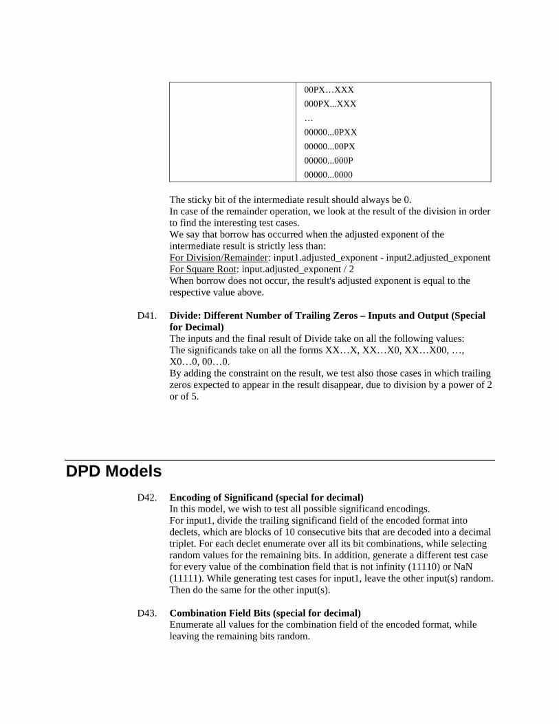
00PX…XXX
000PX...XXX
…
00000...0PXX
00000...00PX
00000...000P
00000...0000
The sticky bit of the intermediate result should always be 0. In case of the remainder operation, we look at the result of the division in order to find the interesting test cases. We say that borrow has occurred when the adjusted exponent of the intermediate result is strictly less than: For Division/Remainder: input1.adjusted_exponent - input2.adjusted_exponent For Square Root: input.adjusted_exponent / 2 When borrow does not occur, the result's adjusted exponent is equal to the respective value above.
D41. Divide: Different Number of Trailing Zeros – Inputs and Output (Special
for Decimal) The inputs and the final result of Divide take on all the following values: The significands take on all the forms XX…X, XX…X0, XX…X00, …, X0…0, 00…0. By adding the constraint on the result, we test also those cases in which trailing zeros expected to appear in the result disappear, due to division by a power of 2 or of 5.
DPD Models D42. Encoding of Significand (special for decimal)
In this model, we wish to test all possible significand encodings. For input1, divide the trailing significand field of the encoded format into declets, which are blocks of 10 consecutive bits that are decoded into a decimal triplet. For each declet enumerate over all its bit combinations, while selecting random values for the remaining bits. In addition, generate a different test case for every value of the combination field that is not infinity (11110) or NaN (11111). While generating test cases for input1, leave the other input(s) random. Then do the same for the other input(s).
D43. Combination Field Bits (special for decimal) Enumerate all values for the combination field of the encoded format, while leaving the remaining bits random.

Document Name • 43