Flight Readiness Review - WordPress.com
62
Flight Readiness Review March 5, 2020 1
Transcript of Flight Readiness Review - WordPress.com

Flight Readiness ReviewMarch 5, 2020
1

2
Sample Acquisition:Erik Benson
Launch Vehicle Recovery:Gabriel Buss
Underclassmen Representative:Trent Couse
Underclassmen Representative:Myers Harbinson
Payload Vehicle:Michael Barton
Payload Integration:Sean Clark
Student Team Leader:Ashby Scruggs
Underclassmen Representative:Alex Thomas

Presentation Overview
• Launch Vehicle Design
• Recovery Subsystem Design
• Demonstration Flight Results
• Payload Design
• Payload Integration Design
• Requirement Verification
3

Launch Vehicle Design
Dimensions
Performance Predictions
Test Results
4

Dimensions of Completed Launch Vehicle
• Final Vehicle Length: 108.06 in
• Filament Wound G12 Fiberglass
• Birch Plywood Fins
5

Nosecone
• 5:1 Ogive shape
• Final length: 31 in
• Metal Tip for reusability
6

Payload Bay
• Final length:24.06 in
• 4 metal screws attach FWD end to Nosecone
• Centering ring placed 6 in from Aft end• Allows for 6 in long coupler
7

Main Parachute Bay
• Length: 18.0 in
• Coupler length: 12 in
• 6 in exposed on FWD end
• Connects to Payload bay with nylon shear pins
• Connects to AV Bay with Metal Screws
8
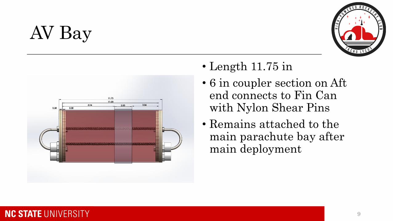
AV Bay
• Length 11.75 in
• 6 in coupler section on Aft end connects to Fin Can with Nylon Shear Pins
• Remains attached to the main parachute bay after main deployment
9

Fin Can
• Length: 33 in
• FWD cavity was expanded 0.5 in
• Motor retainer is attached to motor tube using 2-part epoxy
10

Changes Since CDR
• Number of L-brackets on Nosecone bulkhead increased• From 4 to 6
• Placed at 60 deg. Offsets on alternating sides of bulkhead
11

Bulkhead Tensile Testing
• Bulkhead in tension
• Two-sided test sample• One Epoxied
• One Bolted with #6 bolts
12

Results
• Bolted Side Sheared at 1500 lbs.• Damage to Fiberglass
• Head of two bolts removed from body
• Epoxied side undamaged
• No Visible Damage to U-Bolts
13

Performance Predictions
14
Apogee Predicition (ft)
RockSim BarrowMan
3,775 3,649
Critical Flight Data
Stability (on rail) 2.18
Velocity (rail exit) 70.1 ft/s
Velocity (max) 497 ft/s
Max Mach 0.45

Performance Predictions
15
Vehicle Specifications
Motor L1520T
Mass (loaded) 47.5 lb
Thrust to
Weight7.42

Recovery Subsystem
Parachute Selection
Performance Predictions
Test Results
16
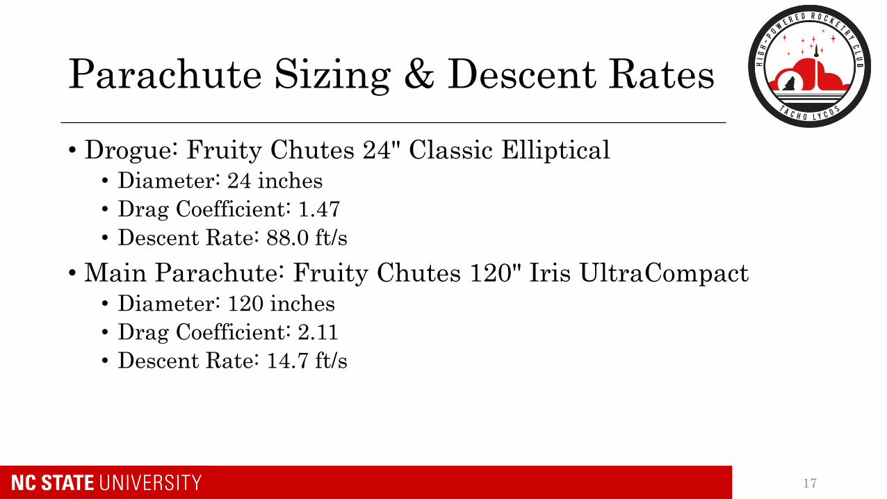
Parachute Sizing & Descent Rates
• Drogue: Fruity Chutes 24" Classic Elliptical• Diameter: 24 inches
• Drag Coefficient: 1.47
• Descent Rate: 88.0 ft/s
• Main Parachute: Fruity Chutes 120" Iris UltraCompact• Diameter: 120 inches
• Drag Coefficient: 2.11
• Descent Rate: 14.7 ft/s
17

Kinetic Energy
18
Section Mass Main Velocity
Kinetic
Energy at
Landing
Drogue
Velocity
Kinetic
Energy under
Drogue
Nosecone .5532 slugs 14.72 ft/s 60. ft-lb 88.00 ft/s 2142.4 ft-lb
Midsection .3916 slugs 14.72 ft/s 42.4 ft-lb 88.00 ft/s 1516.5 ft-lb
Fin can .3792 slugs 14.72 ft/s 41.1 ft-lb 88.00 ft/s 1468.3 ft-lb

Wind Effects on Altitude and Drift
19
Wind Speed Apogee Descent Time Drift Distance
0 mph 3801 ft AGL 67 s 0 ft
5 mph 3792 ft AGL 67 s 490 ft
10 mph 3761 ft AGL 66 s 976 ft
15 mph 3707 ft AGL 66 s 1443 ft
20 mph 3631 ft AGL 63 s 1855 ft
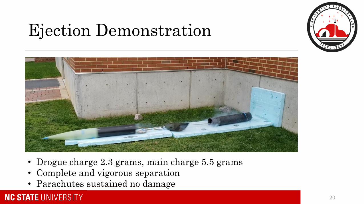
Ejection Demonstration
20
• Drogue charge 2.3 grams, main charge 5.5 grams
• Complete and vigorous separation
• Parachutes sustained no damage

GPS Operational Test
21
• Minimal deviation
from known
course,
approximately 50
ft max deviation
• No delay except
for transmission
frequency (1/sec)
• TTFF of ~ 3
minutes

Tracker Ground Interface
• The GPS systems transmissions received by handheld receiver box
• Linked to Android phone via Bluetooth, uses Rocket Locator App to plot as previous slide
22

Demonstration Flight Results
Vehicle Demonstration Flight
Payload Demonstration Flight
23

Vehicle Demonstration Flight
24
Critical Flight Data
Stability (on rail) 2.17
Apogee 3,187 ft

Vehicle Demonstration Flight
25

Observations
• Minimal weathercocking at rail exit• Fin size was increased based on sub scale demonstration
• Low density altitude (-340 ft MSL)
• 3 lb heavier than predicted• Epoxy weight
• Construction materials
• Recovery electronics and harnesses functioned nominally
26

Payload Demonstration Flight
• The payload was successfully retained during the demonstration flight.
• Due to potential water damage electronic components were not tested at the field
27

Water Damage Avoidance
Removal from Irrigation Ditch Drying BURRITO with Rice
28

Payload DesignBURRITO
SICCU
Test Results
29

BURRITO Overview
• Chassis: laser cut plywood
• Electronics• Arduino Uno: program execution• L298N Motor Driver: motor command• L2596 Buck Converter: voltage adjustment• FRSkyX8R Receiver: control input
• Drivetrain• (2x) 350 RPM planetary gear motors• (2x) Deployable caster wheels
30

BURRITO Overview
Notable Components:
• Chassis
• Electronics Bay
• Drivetrain
• Caster Wheels
Integration Systems:
• SICCU Servos
• Retention Plate
31

BURRITO Dimensions
Dimensions (in.)
32

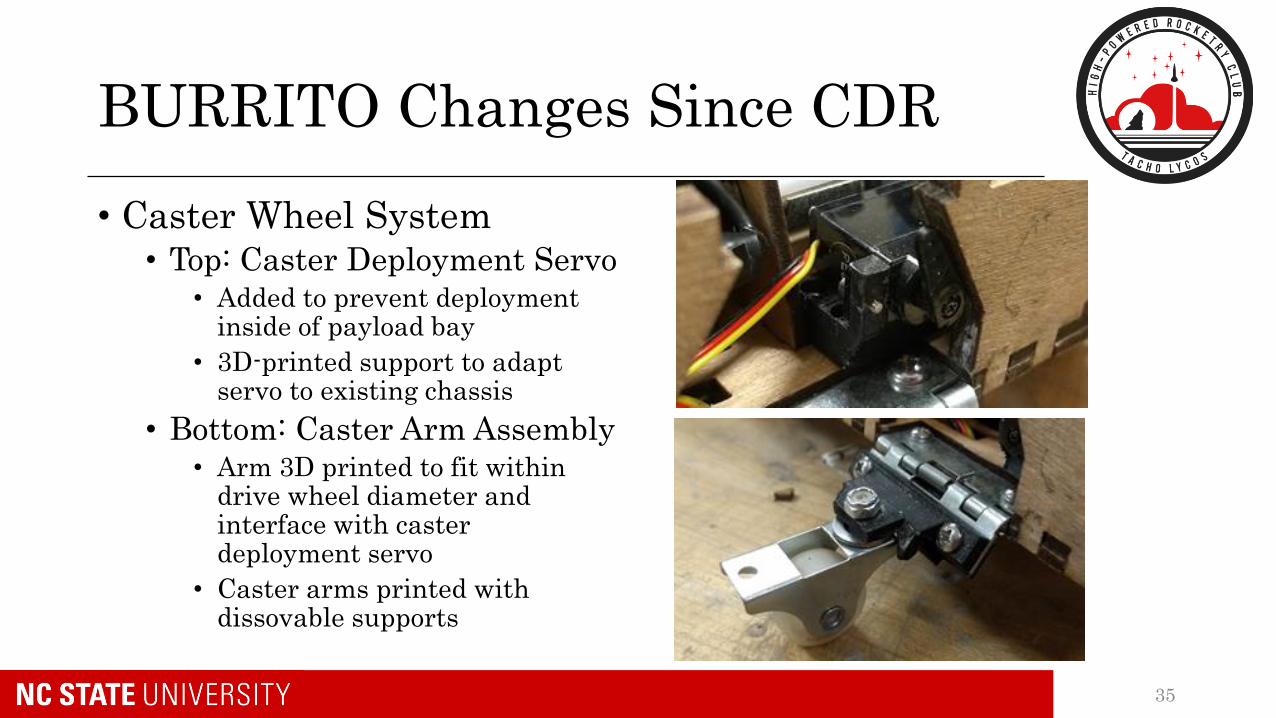
BURRITO Changes Since CDR
• Chassis Construction• Top: Removable upper plate
• Top plate made removable so that interior could be accessed
• Required adhering upward-pointing bolts to allow for fastening of plate
• Bottom: Wood buffers• SICCU gear bracket needed
larger hole cut; hole became oversized
• Small L-shaped pieces were glued in place to prevent bracket movement
33

BURRITO Changes Since CDR
• Drivetrain Construction• Left: Motor Installation
• Divot cut into axle to prevent wheel slipping
• Holes for plate attachment bolts countersunk to allow wheel rotation
• Right: Wheel Installation• Nylon washer drilled and sawed
rather than laser cut
• Base material was standard washer instead of raw material
34
BURRITO Changes Since CDR
• Caster Wheel System• Top: Caster Deployment Servo
• Added to prevent deployment inside of payload bay
• 3D-printed support to adapt servo to existing chassis
• Bottom: Caster Arm Assembly• Arm 3D printed to fit within
drive wheel diameter and interface with caster deployment servo
• Caster arms printed with dissovable supports
35

BURRITO Changes Since CDR
• Electronics Bay• Top: Lid Modifications
• Added rotary switch for power toggling
• Cut hole for power and signal wires to be routed
• Raised for internal volume
• Bottom: Inside Changes• Buck converter added for
voltage regulation
• Buck converter and motor driver attached to ceiling for internal volume
36

BURRITO Operational Tests
• Nominal Performance• Successful driving demo, ~4
mph
• Terrain Performance• Capable of driving in dirt,
gravel, mud, grass, simulated ice
• Inclined/Declined Slopes• High torque able to summit
slopes, no tipping forward or backward
37

BURRITO Operational Tests
• Reorientation• Can return to upright
position from both "nose-down" and upside-down positions
• Control Range• Radio control well beyond
15 ft
• Driving Range• Well above estimated
maximum of 2550 ft
38

SICCU Overview
39
Notable Components:
• Internal Servo
• 2-Member Gear Train
• Aluminum Brace
• Aluminum Arms
• PLA Retention Cover
• Formed and Chamfered Scoops

SICCU Dimensions
• Top of the Servo to Below Cover: 2.04”
• Aluminum Brace Length: 1.25”
• Arm Length: 1.65”
40

SICCU Changes Since CDR
41
• Profile of scoops reduced
• Gear diameter on arm reduced
• Changes driven by geometric constraints• Old design hindered BURRITO's
maneuvering capabilities
• Prevented deployment from payload bay

SICCU Operational Test
• Uncooked rice used as lunar ice simulate
• Each Scoop held 20 mL of rice under ideal conditions
42

Payload Integration
DesignPayload Retention
Payload Deployment
Test Results
43

Retention Plate Components
Finalized CAD Manufactured
44

Retention Plate Modifications
• Shims to eliminate rotation within track• Shim1 -3D printed
• Shim2 – Two thin aluminum sheets
• Spacers to eliminate vertical motion within track• 3d printed spacers to fit height of inner channel
45
• Small excess of tolerances within the guide track slot allowed for too much
movement between the rover interface plate and the retention plate.

Rover Interface Plate
Finalized CAD Manufactured
46
• All components for the rover interface plate were machined at the
NCSU MAE Machine Shop. No modifications were required.
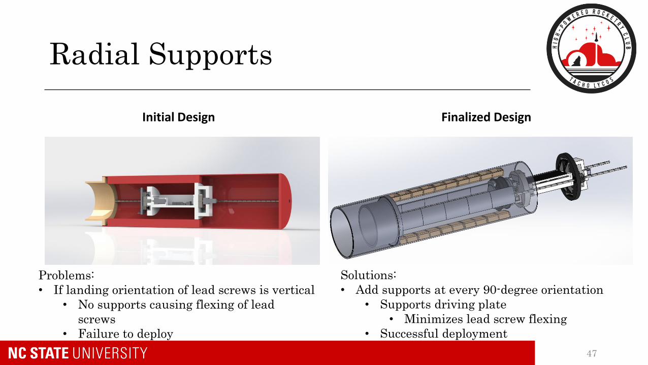
Radial Supports
47
Problems:
• If landing orientation of lead screws is vertical
• No supports causing flexing of lead
screws
• Failure to deploy
Initial Design
Solutions:
• Add supports at every 90-degree orientation
• Supports driving plate
• Minimizes lead screw flexing
• Successful deployment
Finalized Design

Manufactured Supports
Radial Supports Centering Ring and PVC Extrusion
48
• Enough clearance to avoid excess
friction
• Tolerances small enough to
adequately stifle radial motion
• Radial Supports every 90 degrees
support integration system and
rover regardless of landing
orientation

Electronics Bay
49
Padding
• All components soldered to
Ardumoto motor shield as seen.
• Layer of padding implemented to
cushion electronics during flight
• Two, quarter inch dowel rods used
to connect drive plate to E-Bay
• Four, quarter inch dowel rods
connect retention plate to E-Bay
• Shims used to restrain retention
motor and components are super
glued to the E-Bay

Logic and Software
• Once connected to the Bluetooth module within BLE Terminal• Send serial inputs (0-5) to operate independent
motors operational states
• Software GUI records transmissions (outputs)
• Sparkfun Redboard paired with HC-06 module transmits back the operational state
50

Drive Plate
Finalized CAD Manufactured
51
• External gears mounted by set screws into the nuts hub
• Mid gears mounted by a trimmed drill bit super glued into the motor table
and into a small hole in the drive plate
• Drive gear mounted by set screws connecting the gear to the motor shaft

Retention Testing: PLA Structure
PLA Testing Results
52
• PLA Youngs Modulus: 2175𝑙𝑏
𝑖𝑛2
• Yield Strength: 473 𝑙𝑏
𝑖𝑛2(Failed at 710 lbf)

Retention Testing: Full Assembly
• Initial continuous loading to 200 lbf in compression
• Increments of 20lbf added until 360lbf reached
• Failure at 380lbf
• Offers a safety factor of 1.9
53
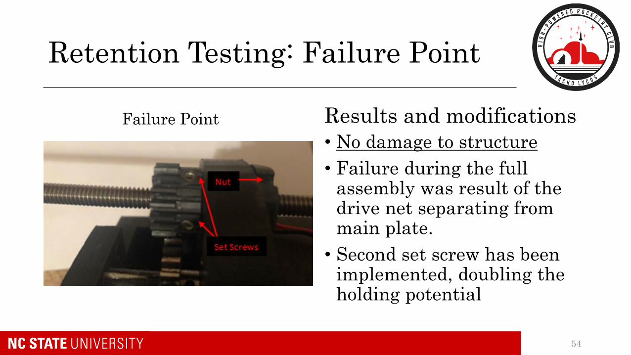
Retention Testing: Failure Point
Failure Point Results and modifications
• No damage to structure
• Failure during the full assembly was result of the drive net separating from main plate.
• Second set screw has been implemented, doubling the holding potential
54

Deployment Testing
Flight orientation Deployment Process
55
Final Modifications:
• Problem: External Gears extruded past drive plate and were interfered with by radial supports
• Solution: Applied Bondo to widen drive plate and sanded new radial supports.

Deployment Process
• From the deployment tests, it was determined that unlocking the rover post deployment introduces cantilever effects too large for the motor to overcome.
Process:
1. Initiate deployment
2. Halt deployment half-way
3. unlock rover1. Rover is still supported by radial supports at this location
4. Proceed with deployment until rover is free.
56

Electronics Testing
Testing Results and modifications
57
• All measured values were under manufactured values• Expected result as maximum values were used in preliminary
calculations
• Note: Redboard current measured with drive motor active and the results will vary dependent on which peripherals are active
• While unnecessary, the team has opted to switch to a 1500 mAh battery that will be capable of running electronics for over a 12 hour period

Requirement Verification
Compliance Plan Status
Launch Vehicle Requirements
Payload Requirements
58
Compliance Plan Status
• Requirements Verified• NASA Handbook Requirements: 131/131 (100%)
• Team Derived Requirements: 40/40 (100%)
• All testing and demonstrations events have been completed for both Payload and Launch vehicle
• The Launch Vehicle and Payload are compliant with all requirements and are mission ready
59

Launch Vehicle Requirements
• The launch Vehicle shall not drift more than a 2,500 ft radius from the launch pad (NASA 3.10)• Complete. During the Launch Vehicle Demonstration Flight, the
onboard GPS recorded a drift distance of approx. 1200ft
• The launch vehicle shall have a static stability margin between 2.0 and 2.3 upon rail exit (TDR 2.5)• Complete. Verified by RockSim analysis
• All critical components of the launch vehicle shall be designed with a minimum safety factor of 1.5 (TDR 2.7)• Complete. All points passing
60

Payload Requirements
• The payload retention system shall be designed to successfully endure flight forces (NASA 4.3.7.2)• Complete. Tested during Retention System Loading Test; all points
passing
• The payload shall recover a lunar ice sample of a minimum of 10 milliliters (NASA 4.3.3)• Complete. Verified via SICCU Operational Test; all points passing
• The payload vehicle shall cover a range of at least 2000 feet (TDR 4.3)• Complete. Verified via BURRITO Range Test; all points passing
61

Questions?
62