
FLIGHT PROTOTYPE AMMONIA STORAGE AND … document consists of 48 pages, 66 copies, Series A FLIGHT...
49
m FLIGHT PROTOTYPE AMMONIA STORAGE AND FEED SYSTEM Prep red by AVCO MISSILES, SPACE AND ELECTRONICS GROUP SPACE SYSTEMS DIVISION Lowell Industrial Park Lowell, Ma s sachusett s 0 185 1 I 1 FINAL REPORT AVSSD-0 100-67-RR I GPO PRICE $ CFSTi PRiCEisj $ Con t r g c t N AS5- 1 0 1 28 Hard copy (HC) Microfiche (M F) 653 July 65 January 1967 Prepared for NATIONAL AERONAUTICS AND SPACE ADMINISTRATION TECHNICAL MANAGEMENT AUXILLARY PROPULSION BRANCH NASA/GODDARD SPACE FLIGHT CENTER Greenbelt, Maryland https://ntrs.nasa.gov/search.jsp?R=19680003766 2018-07-03T08:46:44+00:00Z
Transcript of FLIGHT PROTOTYPE AMMONIA STORAGE AND … document consists of 48 pages, 66 copies, Series A FLIGHT...
m
FLIGHT PROTOTYPE AMMONIA STORAGE AND FEED SYSTEM
P r e p red by
AVCO MISSILES, SPACE AND ELECTRONICS GROUP SPACE SYSTEMS DIVISION
Lowell Industrial P a r k Lowell, Ma s sachusett s 0 185 1
I
1 FINAL REPORT
AVSSD-0 100-67-RR
I GPO PRICE $
CFSTi PRiCEisj $
Con t r g c t N AS5- 1 0 1 28 Hard copy (HC)
Microfiche (M F)
653 July 65
January 1967
Prepared for
NATIONAL AERONAUTICS AND SPACE ADMINISTRATION TECHNICAL MANAGEMENT
AUXILLARY PROPULSION BRANCH NASA/GODDARD SPACE FLIGHT CENTER
Greenbelt, Maryland
https://ntrs.nasa.gov/search.jsp?R=19680003766 2018-07-03T08:46:44+00:00Z
This document consists of 48 pages, 66 copies, Series A
FLIGHT PROTOTYPE AMMONIA STORAGE AND FEED SYSTEM
P r e p red by
AVCO MISSILES, SPACE AND ELECTRONICS GROUP SPACE SYSTEMS DIVISION
Lowell Industrial P a r k Lowell, Ma s sa chusetts 0 185 1
FINAL REPORT
AVSSD-0 100-67-RR Contract NAS5-10128
January 1967
APPROVED
T. K. P u g m i r e , p r o j e c t Director
Prepared for
NATIONAL AERONAUTICS AND SPACE ADMINISTRATION TECHNICAL MANAGEMENT
AUXILJARY PROPULSION BRANCH NASA/GODDARD SPACE FLIGHT CENTER
Greenbelt, Maryland
CONTENTS
Section Page
I. Introduction .......................................... 1
A. P r o g r a m Objectives
C. P r o g r a m Summary ................................ 1
. . . . . . . . . . . . . . . . . . . . . . . . . . . . . . . 1 1 B. P r o g r a m Organization . . . . . . . . . . . . . . . . . . . . . . . . . . . . .
11. Component Design and Development . . . . . . . . . . . . . . . . . . . . . 2
A. Propellant Storage Tank 2 B. 4 C. Flow ControlAssembly, ................ .. ......... . 14 D. 17
.. .. . . . . . . . . . . . . . . . . . . . . .. . . . . . . . . . . . . . P r e s s u r e Regulation and Propellant Feed
Mass Flow Integrator . . . .. . . . . . . . . . . . . . . . . . . . . . . . . . III. Fueling Procedure and Equipment . . . . . . . . . . . . . . . . . . . . . . 18
N. Remaining P r o b l e m A r e a s . .. . . . . . . . . . . . . . . . . . . . . . . . . . . 20
A. Solenoid Valves .................................. 20 B. Fabrication of a Thin-Wall Titanium Tank 21 C. Mater ia ls Compatibility with Ammonia Propellants . . . . 22 D. 22
. . . . . . . . . . . Mass Flow Integrator ....... .. . ... .. .. . . .. .. . . . . ...
Appendices
A. Sizing of the Propellant Storage Tank . . . . . . . . . . . . . . . . . . . 2 3
B. Problems Associated with Fabrication of a Titanium Tank . . 25
C. Pre l iminary S t ress Analysis of a Titanium Propellant Storage Tank and a Stainless Steel Regulation System Plenum Chamber ...................................... 26
. . -11 -
ILLUSTRATIONS
Figure
1.
2.
3.
4.
5.
6.
7.
8.
9.
10.
11.
c -1 .
c -2 .
c-3.
c-4 .
c-5.
C-6.
Page
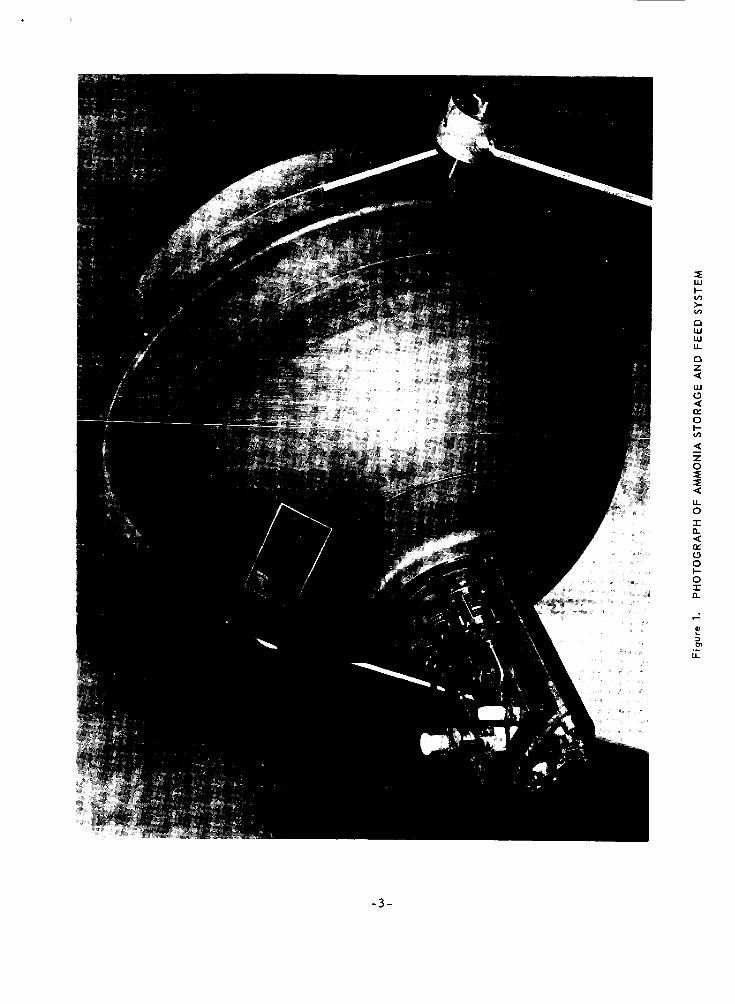
Photograph of Ammonia Storage and Feed System . . . . . . . . . 3
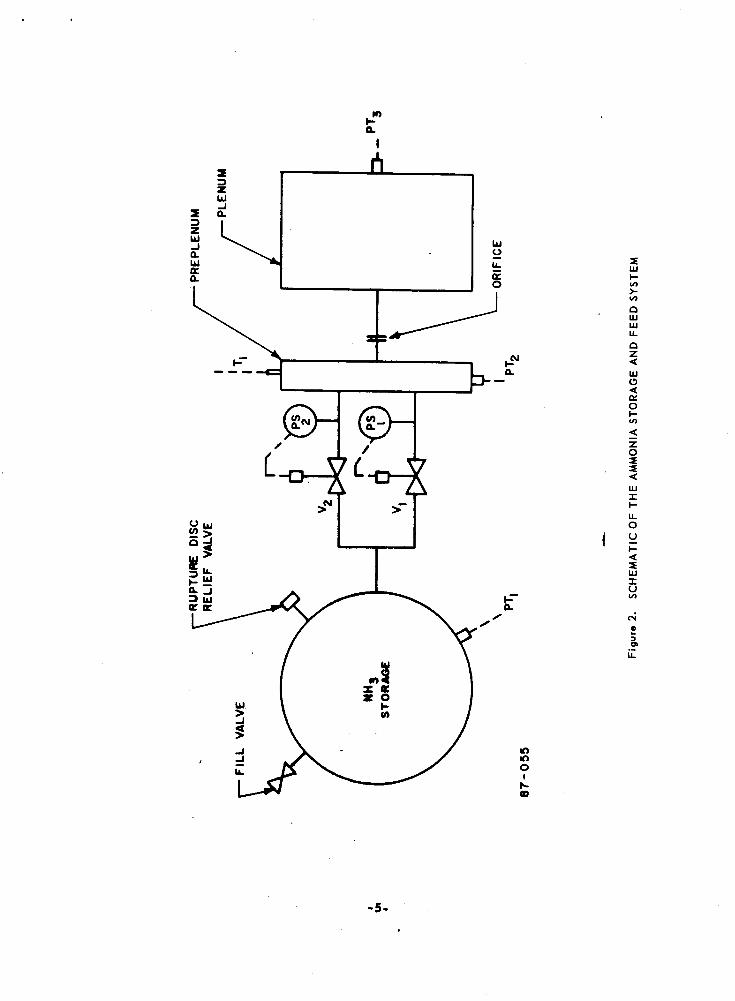
Schematic of the Ammonia Storage and Feed System . . . . . . 5
Photograph of the Regulation and Propellant Feed System . . 6
Preplenum P r e s s u r e Pulse versus Propellant Supply P r e s s u r e ............................................ 7
Regulated Plenum P r e s s u r e versus Propellant Use Rate . . . 8
System Performance Data: Liquid Flow, 30-Mil Orifice, 5-50 P r e s s u r e Switch .. .. . .... ... .. , . . . . .. ..... .... . . . 10
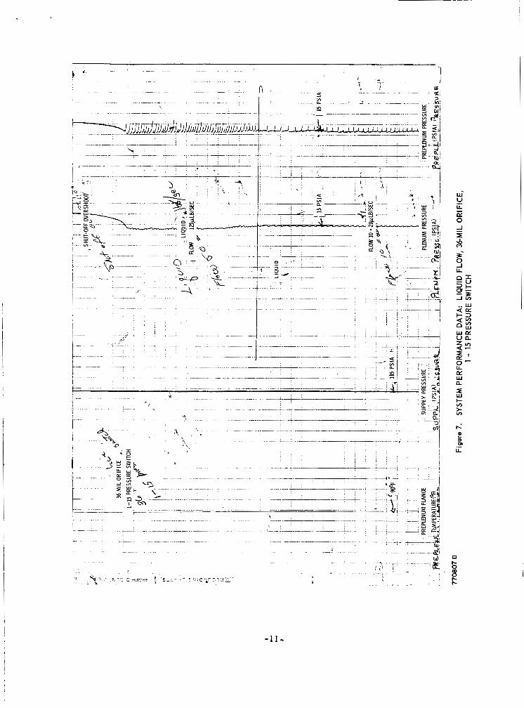
System Performance Data : Liquid Flow, 36 -Mil Orifice, 1-15 P r e s s u r e Switch ................................ 11
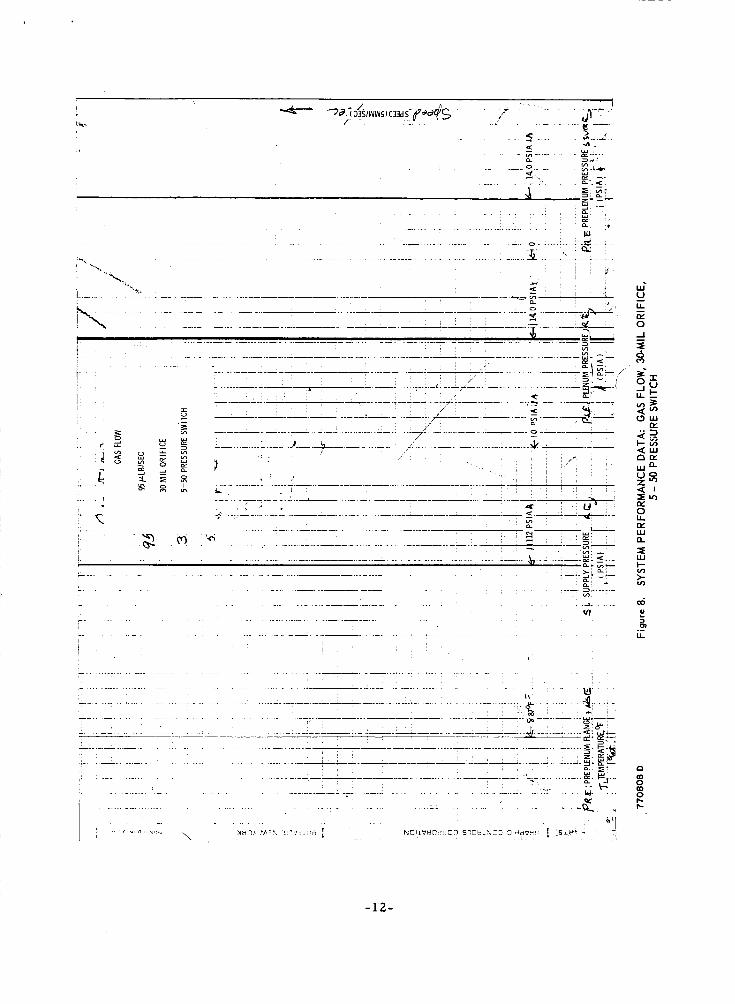
System Performance Data: Gas Flow, 30-Mil Orifice, 5-50 P r e s s u r e Switch . . . . .. . . . . . . . . . . . . . . .. . . . . . . . . . . 12
Preplenum Flange Thermal History for Liquid and Gas Operation .......................................... 13
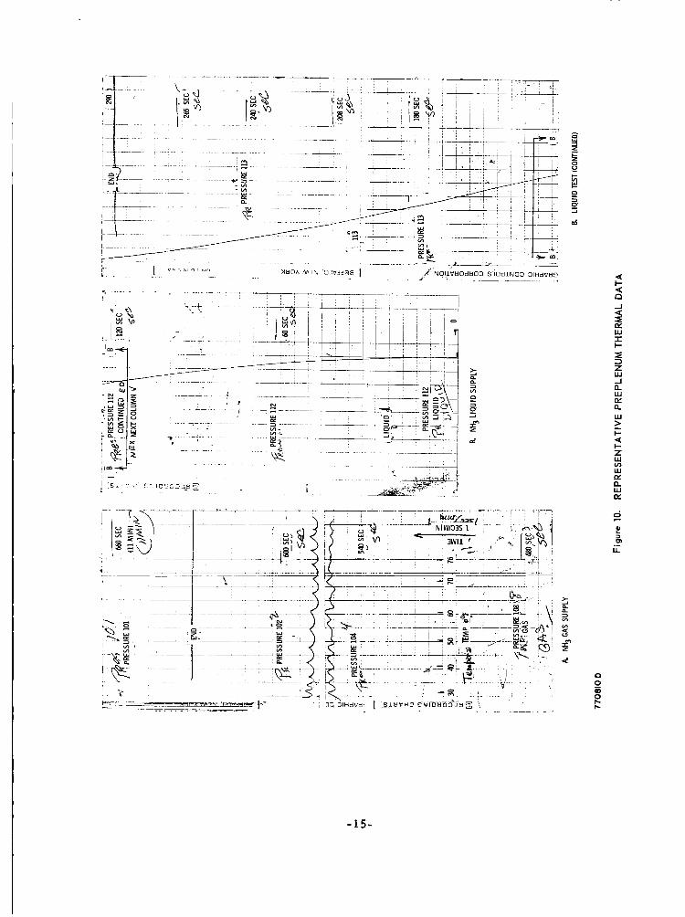
Representative Preplenum Thermal Data . . . . . . . . . . . . . . . , 15
Flow Control Assembly . . . . . . . . . . . . . . . . . . . . . . . . . . . . . . . 16
Analytical Axisymmetr ic Shells and Rings of the Titanium Storage Tank ......................................... 27
Ammonia Storage Tank St ress Intensity a t Design Condition 288 1b/in2, 120°F .................................... 33
Cross Section and Analytical Model of Plenum Chamber . . , 3 4
Storage Tank and Plenum Chamber Configuratioa and Load Orientation ........................................... 37
Dynamic S t ress Analysis Model . . . . . . . . . . . . . . . . . . . . . . . . 41
Ammonia Storage Tank St ress Intensity at Peak Amplifica- tion of Longitudinal Excitation Plus 140 lb/ in2 . . . . . . . . . . . 43
... -111 -
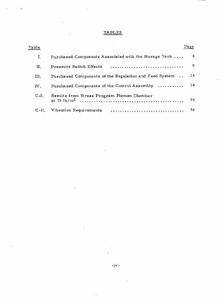
TABLES
Table Page
I, Purchased Components Associated with the Storage Tank .... 4
11. P r e s s u r e Switch Effects ............................... 9
III. Purchased Components of the Regulation and Feed System . . 14
IN. Purchased Components of the Control Assembly ........... 14
C-I. Results f rom St ress P r o g r a m Plenum Chamber 35
C-11. Vibration Requirements ............................... 36
at 75 lb/in2 ............................................
-iv -

I. INTRODUCTION
A. PROGRAM OBJECTIVES
The objective of this program was t o design, develop, fabricate, and tes t a flight-prototype ammonia-propellant storage and feed system. The storage sys tem was to provide storage for 57 pounds of ammonia. ta iner was to be adequate for the environmental conditions specified. The feed sys tem was to provide for a maximum flow condition of 248 x 208 seconds, once per 24-hour period, and a minimum flow ra te of 55. 5 x 10- 6 lb / sec for a single pulse of 0. 015-second duration. sys tem was t o provide no m o r e than 1-percent variation of output p re s su re for the supply pressure associated with the environment temperatures .
The s torage con-
l b / s e c for
The adjustable regulation
B. PROGRAM ORGANIZATION
This program originated f rom the Auxiliary Propulsion Branch of the NASA Goddard Space Flight Center. Mr. William C. Lund was the Technical Officer for NASA GSFC. other participants in th i s program were W. Davis, R . Ingemi, and J. Malenda.
The Project Director of Avco SSD was T. K. Pugmire. The
C. PROGRAM SUMMARY *
A flight -prototype ammonia -propellant storage and feed sys tem suitable for meeting specified environmental qualification was delivered to NASA GSFC. The loaded s torage sys tem will meet the ullage and strength requirements for the conditions specified. regulated p res su re variation,with either liquid or gaseous ammonia. problems observed in the program were the availability of a satisfactory solenoid valve and the fabrication of a titanium tank.
The feed system provides not grea te r than 1 -percent Principle
-1-
11. COMPONENT DESIGN AND DEVELOPMENT
A. PROPELLANT STORAGE TANK
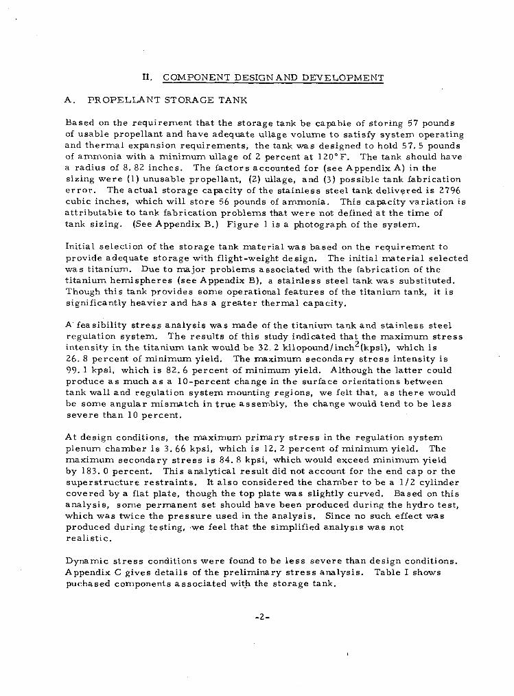
Based on the requirement that the storage tank be capable of storing 57 pounds of usable propellant and have adequate ullage volume t o satisfy sys tem operating and thermal expansion requirements, the tank was designed to hold 57.5 pounds of ammonia with a minimum ullage of 2 percent at 120°F. The tank should have a radius of 8. 82 inches. sizing were (1) unusable propellant, (2) ullage, and ( 3 ) possible tank fabrication e r r o r . The actual storage capacity of the s ta inless s teel tank delivered is 2796 cubic inches, which will s tore 56 pounds of ammonia. attr ibutable to tank fabrication problems that w e r e not defined a t the t ime of tank sizing. (See Appendix B.) Figure 1 i s a photograph of the system.
The factors accounted for (see Appendix A) in the
This capacity variation i s
Initial selection of the storage tank mater ia l was based on the requirement to provide adequate storage with flight-weight design. was titanium. t i tanium hemispheres (see Appendix B), a s ta inless s teel tank was substituted. Thoagh this tank provides some operational features of the titanium tank, it i s significantly heavier and has a grea te r thermal capacity.
The initial mater ia l selected Due to major problems associated with the fabrication of the
A' feasibil i ty s t r e s s analysis was made of the t i tanium tank and s ta inless s teel regulation system. intensity in the t i tanium tank would be 32. 2 kilopound/inch2(kpsi), which is 26. 8 percent of minimum yield. 99. 1 kpsi, which is 82.6 percent of minimum yield. produce a s much a s a 10-percent change in the surface orientations between tank wall and regulation sys tem mounting regions, we felt that, a s there would be some angular mismatch in t rue assembly, the change would tend t o be l e s s severe than 10 percent.
The resu l t s of this study indicated that the maximum s t r e s s
The maximum secondary s t r e s s intensity is Although the la t ter could
At design conditions, the maximum primary s t r e s s in the regulation sys tem plenum chamber i s 3 . 66 kpsi, which i s 12. 2 percent of minimum yield. The maximum secondary s t r e s s i s 84.8 kpsi, which would exceed minimum yield by 183. 0 percent. supers t ruc ture res t ra in ts . It a l so considered the chamber to be a 1 / 2 cylinder covered by a flat plate, though the top plate was slightly curved. Based on this analysis , some permanent set should have been produced during the hydro tes t , which was twice the p re s su re used in the analysis. produced during testing, ,we feel that the simplified analysis was not r e ali s t i c .
This analytical result did not account for the end cap or the
Since no such effect was
Dynamic s t r e s s conditions were found to be less severe than design conditions. Appendix C gives details of the preliminary s t r e s s analysis. puchased components associated with the storage tank.
Table I shows
-2 -
n Z 4: W 0 4 E 0 I-
4: v)
L 0
a 4 E 0 0 I- O
r
r n -
-3 -

TABLE I
PURCHASED COMPONENTS ASSOCIATED WITH THE STORAGE TANK
.___
Component
Storage Tank
P r e s s u r e Transducer
Fil l Valve
Burst Disk Relief Valve
Ma nufa ct u r e r
Elektr on Standard, Inc.
Micro Systems
Py r onet i c s , Inc . Carleton Controls, Corp.
Model Number
1003-0046; 0-300 psia
1176-46
1962 -006 -7
B. PRESSURE REGULATION AND PROPELLANT FEED
The function of the p re s su re regulation and propeiiant feed system is to provide gaseous ammonia on demand a t a predetermined pressure . required that there be no more than 1-percent variation of the regulated pressure . The sys tem i s required to meet this specification with either gas o r liquid input f r o m the s torage tank (must function under ze ro gravity conditions). A schematic of the s torage and feed sys tem is shown in Figure 2, and a photograph of the feed sys t em is shown in Figure 3.
Referr ing t o Figure 2, the principal elements of the regulation sys tem a r e the p re s su re switch (PS), solenoid valve (V)--the system includes two of each for paral le l redundancy: PS1, PS2, V1, and V2--and two chambers separated by a n orifice. Flow f r o m the storage tank t o the preplenum chamber i s controlled by the solenoid valve, which is actuated by the p re s su re switch.
The specifications
Using a var iable setting pressure switch (5-50 psid--manufacturer-stated dead band, 4. 5 lb/ in2) se t to shut off at 15 psia (worse control case), the preplenum pres su re data shown in Figure 4 were obtained for gas and liquid flow f r o m the s torage tank over a range of supply tank pressures .
The effect of the dual chamber (preplenum and plenum) and the connecting orifice is shown by the plenum pres su re fluctuation data in Figure 5. taken a t supply p re s su res of 115, 135, 155, and 230 psia, over a range of flow conditions. p re s su re of 15 psia, liquid flow f r o m the storage tank at 155 psia, and a pro- pellant use ra te of 20 x led p re s su re t o * 1.01 percent. F o r all other flow o r pressure conditions specified in the contract, it w a s pos-sible to control regulated p res su re t o be t te r than f 1. 0 percent,
These data were
The worst-case pressure-regulation conditions a r e a regulated
lb / sec . Under these conditions, the sys t em control-
-4 -
cm n I
I W
r? 5;
' 2 W LL
Z a W (3 a K 0
n
r? a - Z 0 I I a
LL 0
w
-5-

n
n 0 4!
n a
0
Z
Z
I- a -I 3 0 w 4! W I I- LL 0 I a a 4! u 0 I- O I n
-6 -
0 CD N
0 d N
0 * N
- 7 -
LL
v) 0
m
I 0
13
16
+-
W L
k CY W v)
3 I- z 4
-8-
The data of Figure 5 a l so demonstrate the effect on regulated p res su re variation caused by the dead band of the p re s su re switch. The C2069-3 switch has a nor- mal dead band of 4.5 psia. To obtain f 1.0-percent regulated pressure control, the p re s su re switch should be selected fo r its appropriate range of operation. This is indicated in Table 11. (Note: The re is in the sys tem a basic tradeoff between valve cycling ra te and p res - s u r e regulation variation--the bet ter the control, the higher the valve cycling rate. )
The C2069-1 switch has a dead band of 1.5 psia.
TABLE II
PRESSURE SWITCH EFFECTS
P r e s s u r e Switch
Model Number
Normal M a x i m u m M a x i m u m Regulated N o r m a l Dead Switch P r e p l e n u m P r e s s u r e P l e n u m P r e s s u r e
V a r i a t i o n Opera t ing Range Band Setting Va r iati on (psid) ( lb / in2) (ps ia ) (percent ) (percent )
CZO69-3 4. 5 C2069-3 5-50 4.5
Sections of recorded sys tem performance data a r e shown i n F igures 6, 7, and 8.
~ _ _ _ _ ~ ~~
15 53 1.01 15 80 4. 86 50 22 0. 95
A s indicated previously, the regulation system has been designed with a paral le l redundancy of two regulating valves and two p res su re switches. In this system, one switch i s set a t a p re s su re slightly below (0.5 lb / in ) the other p re s su re switch. Therefore, should one valve-switch combination fail closed, the other would commence controlling when the plenum-preplenum pres su re dropped the additional 0. 5 lb/ in2 due t o flow usage.
2
The components of the regulation and feed sys tem a r e shown in Table III.
E a r l y analytical predictions were nearly cor rec t concerning the adequacy of the thermal capability of the sys tem to provide the energy for ammonia vaporization. F o r the worst condition (i. e. , a maximum flow rate , 248 x l b / s e c at 20°F for 208 seconds, with 3 .30 pounds of propellant remaining in the storage tank), the sys t em was able to maintain the specified control. plenam flange temperature was monitored. The data shown in Figure 9 were takzn during two t e s t s at station-keeping flow conditions with liquid ammonia entering the regulation system. The temperature of the propellant storage tank remained near ly constant for these runs. A third tes t was made withdrawing gaseous ammonia for 660 seconds. The total sys tem tempera ture change was l e s s than 1°F. walls would have a la rger temperature change, bu4 based on actual tankage weights,
During this tes t , the pre-
This is a l so shown in Figure 9. (Note: The titanium tank with i t s thinner
-9-
G --I! . Q
-10-
-11-
w a
i-
-12-

0 8
0 m N
0 0 N
-
0 s
0 0
v, a n
0 0
c3
Z Q
3
-I E 0 U t. L1? 0 I-
- 1 3 -
- -
Ma nufa ctur e r
I
Model Number
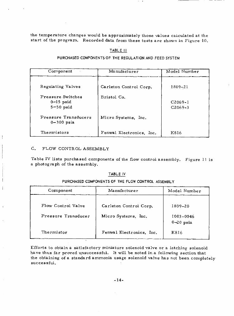
the tempera ture changes would be approximately those values calculated a t the s t a r t of the program. Recorded data f rom these tes t s a r e shown in Figure -10.
TABLE I l l
PURCHASED COMPONENTS OF THE REGULATION AND FEED SYSTEM
Component
Regulating Valve s
Pres su re Switches 0-15 psid 5-50 psid
Pres su re Transducers 0-300 psia
The rmi s t o r s
Ma nufa ctur e r
Carleton Control Corp.
Bristol Co.
Micro Systems, Inc.
Fenwal Electronics, h c .
Model Number
1809-21
C2069-1 C2069-3
K816
C. FLOW CONTROL ASSEMBLY
Table IV lists purchased components of the flow control assembly. a photograph of the assembly.
Figure 11 is
TABLE IV
PURCHASED COMPONENTS OF THE FLOW CONTROL ASSEMBLY
Component 4 I Flow Control Valve I Carleton Control Corp. 1 1809-20
Pres su re Transducer Micro Systems, h c . 1003 -0046 0-20 psia
The rmi s t o r Fenwal Electronics, Inc.
Efforts t o obtain a satisfactory miniature solenoid valve or a latching solenoid have thus far proved unsuccessful. the obtaining of a standard ammonia usage solenoid valve has not been completely successful.
It will be noted in a following section that
- 14-
0
-15-

Figure 11. FLOW CONTROL ASSEMBLY
-16-
D. MASS FLOW INTEGRATOR
The m a s s flow integrator w a s developed to meet the requirements of providing a measurement of propellant m a s s o r level when the sys t em i s in a t e s t vacuum chamber. It was felt that could a n instrument be developed that would a l s o func- t ion in a space, zero-g environment, such a n instrument would fulfill a need a s s o - ciated with severa l other types of propellant. Therefore, additional developments w e r e s tar ted on a unit, conceived before this contract, that would use the p re s su re drop a c r o s s the preplenum-plenum orifice for a n analog measurement of the m a s s flow passing through the orifice. grated analog signal would be converted to a digital count, which would then be stored. l ished by subtracting the propellant removed f r o m the initial amount.
To eliminate the usual c i rcui t drift , the inte-
The determination of propellant remaining in the fuel tank would be estab-
Coupling this concept t o the actual operation of the ammonia regulation sys t em involved considerably m o r e activity than anticipated. with a laboratory breadboard model of the mass flow integrator and a n ammonia feed system, the integrator operated completely satisfactorily. Both with liquid- and gaseous-ammonia flow being introduced into the regulation system, the inte- gra tor counted the mass flow with a n accuracy of bet ter than 97 percent. Tem- perature effects could account for most of the counting e r r o r .
In a tes t run, however,
Previous t e s t s of the integrator with a i r flow were compared t o measurements made f r o m flow orifice calculations. Several runs at given m a s s flow ra tes and a t th ree plenum pres su res were made arkd the resu l t s averaged. In general , the peak-to-peak count variation for the seven count intervals was ve ry small, am- mounting to perhaps 1. 5 percent count accuracy a t each of the three plenum pres su res showed deviations of l e s s than 1 percent for flow ra t e s f rom about 50 t o 150 p lb / sec . Finally, the cumu- lative e r r o r when both varying plenum pressure and m a s s flow ra te was about 7 percent maximum. This cumulative e r r o r can be reduced, a s the runs were made with a preplenum transducer sensitivity having a positive output a t ze ro p re s su re .
(Details a r e provided in Appendix D. ) The
The e r r o r introduced by this would tend to nulify the cumulative e r r o r .
-17-
III. FUELING PROCEDURE AND EQUIPMENT
Three factors a r e he re considered for the fueling operation: (1) the purity of the propellant, (2) the cleanness of the fueling equipment (particularly the connecting points), and (3) the amount of propellant t ransferred. The actual fueling proce- du re is outlined below, together with several general comments about the operation.
1) 1 hour. Then, close fill valve and turn off and disconnect pump. This allows sufficient and accura te f i l l of ammonia and reduces contamination of the tank- a g e system.
Evacuate storage tank to at least 1 t o r r , and maintain vacuum pumping for
2) the s torage tank. sea t manual valve (Whitey type) and a very short length of 1/8-inch s ta inless- s tee l tubing, having an AN-type fitting for attachment to the f i l l valve. container should be ultra-sonically cleaned (no chlorine), evacuated, weighed, and then filled with high-purity ammonia (careful not to overfill). t a iner is then reweighed and connected, and the ammonia t ransfer red to tank. (Over filling can occur should the density of the liquid ammonia increase during the t ransfer process , and should the container be nearly filled with higher density ammonia: when the ammonia is warmed, the density de- c r e a s e s and ex t reme p res su res can be obtained. )
Use a s ta inless s teel p re s su re container for portage of the ammonia to This container should be equipped with a 1 /4-inch Ke l -F
The
The con-
The container is again weighed to determine the amount t ransfer red .
3 ) inch wrench by turning the thin concentric nut counter-clockwise until it again begins to indicate res is tance t o turning. operator should be familiar with the valve. ammonia to be t ransfer red into the storage tank. f e r l ine valve and then the storage-tank f i l l valve. ambient conditions.
After connecting t o the f i l l valve, the f i l l valve is opened with a 9/16-
(Before operating system, Allow a small amount of
Close the manual t r ans - Allow tank to a r r ive a t
This will accomplish the following:
a ) Control the rate of p re s su re r i s e in the storage tank.
b) Allow for leak checking in system.
c) tu re drop. on the wall opposite the f i l l tube, a la rge local temperature drop will occur. )
Allow subsequent liquid t ransfer with a minimum of local tempera- (When liquid flashes into the evacuated tank and impinges
4) Re-open storage-tank f i l l valve, and then open manual t ransfer line valve to continue fuel t ransfer process. plished as quickly as possible in order to keep the t ime available for liquid expansion short .
Fueling now should be a c o r n -
-18-
The filling procedure is accelerated if the f i l l container is higher than the exit tube. To fur ther acce lera te the t ransfer , a heat gun may be directed over the f i l l container; be certain, however, that both the f i l l valve and hand valve a r e open before applying heat. propellant storage tank. This may be done with ice packs, ice bath, o r cooling coils.
Another technique is t o chill the
Usually, the completion of the t ransfer can be determined by the end of the sound of running liquid. The fill valve is then closed with 5 inch-pounds of torque, the hand valve shut off, and the p re s su re in the t ransfer line r e - leased slowly as the connecting fittings a r e loosened. This t ransfer line should be kept extremely short downstream of the hand valve.) This procedure is repeated until sufficient propellant has been t ransferred.
The total tank volume has been measured at 2796 i n ~ h e s . ~ Therefore, the maximum amount of NH3 that should ever be loaded is 56.0 pounds.
IV. REMAINING PROBLEM AREAS
In general , the sys tem delivered meets all of the specifications of the contract . Several significant problem a r e a s remain, however. Pr incipal of these a r e (1) the availability of a reliable ammonia-usage solenoid valve, (2) fabrication of a thin-wall t i tanium storage tank, (3) evaluation of mater ia l s compatibility with a rea l i s t ic purity ammonia, and (4) fabrication and testing of a flight-qualified m a s s flow integrator.
A. SOLENOID VALVE
The most consistent problem in the program has been the solenoid valves. problem s t ems f rom the fact that existing qualified valves have been modified and adapted to a new application. Before the s t a r t of this program, Avco had done a survey of available valves for use on ammonia auxiliary propulsion sys- tems . inputs f r o m AVCO, Carleton Controls adapted a n existing valve for low-flow a m - monia.
This
The findings showed that the desired valve was not available. Based on
The designation of this new valve s e r i e s was 1809.
Initial laboratory use of this valve demonstrated a problem of flow directior, s f liquid ammonia and valve bellows. was put back into life testing and sys tem use. During life tests, severa l of the valves successfully passed (leak r a t e s less than 6 x hundreds of thousands of cycles. It was later observed, however, that this s ame valve could fail a f te r a few (10 t o 1000) cycles when exposed to high purity a m - monia. The problem was diagnosed to be the chemical bonding agent used to hold the valve seat in place. Solution of this problem followed development and t e s t of severa l methods of mechanically holding the seat in place.
Following correct ion of this problem, the valve
STD cm3/sec of He)
Later , another major valve problem w a s discovered. use of the 1809 valve, a problem diagnosed a s valve adjustment was observed. Valves were assembled and checked a t Carleton Controls and shipped t o Avco. Subsequent testing of the valves a t Avco indicated valve sticking or high leak rates . Additional valve adjustment would co r rec t the problem. The Massachuset ts Institute of Technology, Lincoln Laboratory, reported the same problem. Several t i m e s during the environmental testing of this valve, changes of adjustment were observed. the resu l t of the design of the valve case and the small case se t screws. (A part ia l t u r n of one of the small set screws could change the valve adjustment f r o m fully closed t o leaking.) A fur ther modification t o the valve apparently cor rec ted this problem; during a l a t e r vibration test , however, a modified valve was observed to be stuck closed and would not respond when a voltage was applied t o open the valve. The environmental testing of the valve has a l s o demonstrated that this valve would dribble during vibration loading.
Throughout the period of
During August, the adjustment problem was determined to be
(The valve functioned properly a f te r being tapped. )
-20-
Carleton Controls was given a full report of the valve tes t resul ts . a l s o informed that both Avco and Goddard (W. Lund and D. Suddeth) considered the valve unsatisfactory.
They were
The following recommendations were a l s o made:
Valve housing should be either welded together o r made in one part (permanent assembly).
The necessity for valve adjustment should be completely eliminated.
The requirements for eight nated.
O-rings within the valve should be el imi- Welding following assembly was recommended.
Should the valve require mechanical assembly, the cor rec tness of the assembl ies must be capable of verification by a n external positive test .
The valve must remain closed when subjected t o a launch environment.
The valve must open when energized with a n equivalent solenoid force of 75 g.
Reliability is more important than minimum pnwer use.
These recommendations, together with the performance and quality a s su rance specifications, were a l s o given to other valve manufacturers. New valve con- ceptual designs were received f rom three companies. These designs were r e - viewed with NASAIGoddard, NASA/ Lewis, and M. I. T. Lincoln Laboratory. review comments w e r e in tu rn relayed t o the respective manufacturers. type valves for evaluation testing were later received f rom two companies. During the initial testing, one of the valves failed leak-rate tes ts . returned t o the vendor, who diagnosed the problem a s contamination inside the valve. second company were put into preliminary cycling with ammonia flow before leak testing. Due t o external leakage of ammonia through the valve housing, all four valves had to be returned to the vendor. This leakage was the resul t of the am- monia reacting with the solder holding the housing together. that the reason he had not welded the valve together was to allow such repairs o r modifications t o be made that should be required as a resul t of the evaluation testing .)
The Pro to-
The valve was
This valve was built with f i l ters at both ends. Four valves f r o m the
(The vendor said
B. FABRICATION O F A THIN-WALL TITANIUM TANK
In theory, the most economical method f o r fabrication of a thin-wall t i tanium hemi- sphere would be by spinning. A s indicated in a previous section and in Appendix B, however, significant prob- l ems have been observed using this process. Elektron Standard, Inc., and Spincraft of Milwaukee is attempting to fa5ricate the
Tank assembly could then be completed by welding.
An Avco funded program with
-21-
desired tank by spinning and electron-beam welding. spinning procedures outlined in Appendix B were used t o spin acceptable hemi- spheres. i n the process of being assembled with the mounting flanges by electron beam welding.
On this program, the
At the t ime of the preparation of this report the hemispheres were
C. MATERIALS COMPATIBILITY WITH AMMONIA PROPELLANTS
Mater ia ls handbooks indicate a grea t number of mater ia ls , including aluminum and copper, a r e compatible with chemically pure ammonia. In actual usage, however, it has been observed that "high-purity" ammonia obtained. f r o m suppli- e r s is not pure. There is, for example, always some quantity of water. (Avco always processed this "high-purity" ammonia through several additional dis t i l - lations and fi l terings. ) There is a l s o some degree of contamination ca r r i ed by the contact sur face of the respective material . the compatibility guides for pure ammonia cannot be followed.
Consequently, in actual usage,
A program should be established t o evaluate the compatibility factor for t emper - a t u r e ranges of interest for pure ammonia and propellants containing ammonia, such a s many of the subliming solids.
D. MASS FLOW INTEGRATOR
This instrument shows promise not only f o r use i n ammonia systems, but a l so with all other liquid or solid propellants that a r e converted to a gas before expul- sion f r o m the thrus t nozzle. refinement of a temperature compensator, measurement accurac ies of g rea t e r than 95 percent can be obtained with a light-weight ( less than 0. 25 pound) low- power (less than 1 watt) flight unit.
We believe that, with the addition of a n instrument
-22-

APPENDIX A
SIZING O F THE PROPELLANT STORAGE TANK
The volume of the propellant tank, accounting for the preplenum boss is
V = 413 rrR3 - nh2 ( R - h / ,
where R is the tank radius, and h i s the height of the spherical segment cf tank removed by the preplenum. ullage requirements.
Determination of volume i s based on the tankage and These requirements a re reviewed in the following section.
A . UNUSABLE PROPELLANT
Propellant remaining in the tank, preplenum, and plenum when the pressure in these volumes has reached the assigned minimum lock-up p res su re constitutes the depleted condition. The maximum specified lock-up p res su re is 75 psia.
The following a r e the approximate volumes involved:
Tank
Pr e pl enum
P1 e num
Total System Volume
The amount of gas contained
3
3
3
- - 2891.0 i n
0 . 5 i n
- - 40.0 in
- -
3 = 2931.5 in
in the system at 75 psia and 20" F (the conditions for -
maximum residual m a s s ) can be determined f r o m the universal equation:
mPV R T '
M = -
where
M = weight, pounds
m
P
v = volume 2932/1728 (ft3)
R
3 = molecular weight = 17. 03 pounds fo r NH
= absolute p re s su re = 75 x 144 (lb/ft ) 2
= universal constant, NH3.= 1537. 8 (ft-lb/OR)
-23 -
I
T = t empera ture = 460 t 20 = 480 (OR)
M = 0.4228 pound.
Propellant lost f r o m the sys tem during a 3-year mission has been estimated on the bas i s of measurements taken on a previous laboratory ammonia storage and feed system. This is felt to be a reasonable approximation, a s the number and length of tank welds, number of valves, types of valves, e tc . , a r e similar. This value is 0. 100 pound.
B. ULLAGE
All c r i te r ia for tank ullage in a flight system a r e difficult to establish. this sys tem has been established by providing a full tankage a t 130"F, ammonia density t o 34. 67 lb/ft3, ra ther than the specified maximum operational t emper - a tu re of 120°F. The sys tem is additionally protected by a rupture disk and relief valve. )
Ullage for
This allows approximately 2 percent ullage at 120°F. (Note:
C. VOLUME SENSITIVITY TO FABRICATION ERROR
The zxmximum anticipated fabrication e r r o r is 2 mils. 8.816 inches, the percentage of volume change per mi l e r r o r is 0.034 percent. Therefore, a 0.07-percent volume e r r o r i s associated with a 2-mil e r r o r .
For a tank radius of
F r o m the preceding factors and the specified 57.00 pounds of usable propellant, a propellant load of 57.523 pounds i s established. (value associated with 130"F), the required tank volume i s 1.659 f t ? Following a n i terat ive process , the tank radius was established a s 8.816 inches.
F r o m the value of 34.67 lb/ft3
-24-
APPENDIX B
PROBLEMS ASSOCIATED WITH FABRICATION O F A TITANIUM TANK
Elektron Standard, Inc., of South Windsor, Connecticut, the firm selected by Avco to have responsibility for fabrication of the titanium tank, surveyed 10 t i tanium metal-forming companies before selecting Eas te rn Metals, of Eas t Hartford, Connecticut, for fabrication of the titanium hemispheres. These hemispheres were to be subsequently assembled by electron beam welding by E le kt r on Standa rd.
The first-finished spun hemispheres exhibited many s t r e s s l ines and multiple cracking around the periphery, 3 inches from the edge. a t tempts by Eastern, using extra s t r e s s relieving operations (950°F for 8 hours) between spinnings, showed little improvement in the f i n a l hemispheres.
Subsequent spinning
The f i n a l approach used by Eas te rn was t o start the operation with a thicker mater ia l and use contour machining following the spinning operation in order t o obtain the final configuration. techfiiquc was used to fabricate the staiiiless s teel “uckup taiik ordered by Avco. The resu l t s were successful, although the tolerances on the internal dimensions of the tank were not maintained. produced bet ter resu l t s than obtained previously, but they were still f a r f r o m satisfactory, and the parts had t o be rejected.
To gain experience with this approach, the
Subsequent work on the t i tanium hemispheres
The spinning procedure used by Eas te rn was t o heat the mater ia l with torches to 1100” t o 1300°F for each break. Between breaks, the mater ia l w a s annealed.
In a subsequent attempt, Eas te rn gave the mater ia l a 2 t o 4 micro-finish before start ing the spinning. The f i n a l product of th is effort was equally unsatisfactory.
The following comments and recommendations a r e based on a n Avco study of the spinning procedures used for the titanium.
1) The titanium should be heated more uniformly than can be done with torches. Radiant heating lamps a r e suggested.
2 ) The torch heating likely produces hydrogen embrit t lement of mater ia l .
3) Final rounding of the mater ia l could be achieved with inside machining. This would eliminate the final break of the spinning procedure. (Most of the par t fa i lures were observed to occur in the region of the f i n a l break. )
-25 -

APPENDIX C
PRELIMINARY STRESS ANALYSIS O F A TITANIUM PROPELLANT STORAGE TANK AND A STAINLESS STEEL REGULATION SYSTEM PLENUM CHAMBER
I
A. STATIC ANALYSIS O F THE PROPELLANT STORAGE TANK
1. Design Conditions
The tank contains 5 7 pounds of saturated ammonia at a maximum tempera- t u re of 120"F, which corresponds t o 288 psia. External p re s su re i s zero. The tank is titanium, and the plenum chamber attached t o the tank i s stain- l e s s steel . Thus, there is a differential thermal expansion at 120°F, since assembly takes place at room temperature. bolt c i rc le . ditions.
The tank is supported a t the Support reaction i s assumed negligible under s ta t ic design con-
Material properties a r e the following:
Titanium Stainless 2 30 klb/in 2 Yield strength 120 klb/in
U It i ma t e strength
Coefficient of expansion 4. 8 x 9.6 x
Young ' s modulus 16, 000 klb/in2 28, 000 klb/in2
130 klb/in2 7 5 klb / in2
3 0. 29 lb / in 0. 16 lb/ in 3 Density
Ti-6A1-4V propert ies f rom MIL-HDBK-5, annealed condition 304 SST propert ies f rom U. S. Steel Data Sheet, annealed condition.
2. Static Analysis Model of Storage Tank
The titanium tank has been divided into axisymmetr ic shells and r ings for analysis by a previously developed computer program ( P r o g r a m 1888). These regions a r e shown in Figure C-1 and described in the following pa r a g r a ph s .
-26 -

W I I- LL 0
i a Z 4:
-27-

Region 1
Mat e rial : Titanium P r e s s u r e : 288 lb/ in2 Temperature: + 50 degrees
This short region i s employed to improve accuracy a t the pole point. Shell thickness i s the minimum.
Region 2
Mat e rial : Titanium P r e s su re : 288 lb/ in2 Temperature: t 50 degrees
This region completes the constant thickness spherical end.
Region 3
0.04
2 Mater ia l : T ita ni um P r e s s u r e : 288 lb/ in Temperature: t 50 degrees
-28-

The reference face of Region 2 in order t o account for the thickness discontinuity. The thickness variation i s assumed l inear between the region end points.
surface is taken a s a continuation of the spherical s u r -
Region 4
lR-2.375 0.25%-F Material : 304 SST P r e s s u r e : Temperature: t 50 degrees
288 lb / in 2
This region simulates the plenum chamber end plate; 2 .375 is the bolt c i rc le radius. 0. 25-inch thickness is a compromise with the penetra- t ions and other a r e a s where mater ia l is removed.
Region 5
Mat e rial : Titanium Temperature: t 50 degrees
0.13 4 0.689
0.375
- REGION 4 INTERACTS HERE
REGION 6
Region 5 is a ring made up f rom the mater ia l left between 4 and 6.
Cross section a r e a =
Cross section inertia = 0. 0125 in
Radius t o c. g. = 2 . 4 inches
0.4 in 2
4
Axial location of interaction points with adjacent regions:
Region 4: 0. 2 inch to right of c. g.
Region 6: 0. 394 inch t o left of c. g.
-29-
Net p re s su re loads on ring:
171. 1 lb/in, radial
220. 8/2.4 lb/in, axial
55. 96 in lb/in, moment
Region 6
R = 8 .832 INCHE AT THIS POINT
S 1.675
7 R.6.772 INCHES ALONG THIS SURFACE
T
Starting with the dimensions shown above, we computed the following Region 6 dimensions.
-7- 4.65
REFERENCE SURFACE
MATERIAL : TITANIUM
PRESSURE : 288 Ib / ln*
3 17.8S0 TEMPERATURE : + 5 0 drgr r ra
-30-

The thickness variation i s assumed linear between the region end points.
Region 7
T ita ni um Mat e ria 1 : P r e s sure : 288 lb l in Tempera ture : t 50 degrees
2
Region 8
Region8 i s a m i r r o r image of Region 3 .
Region 9
Mat e ria 1 : Tempera ture : + 50 degrees
T ita ni um
R = 9.5 BOLT CIRCLE 16.0
I N T E R A C T I O N POINT 1 WITH REGIONS 3 ANDB- R = 9.3 RING C.G.
LR= 8.832
This region is a ring c r o s s section: a r e a = 0. 1 2 in.
-4. 4 c r o s s section: iner t ia = 1.5 x 10 In
No net p re s su re load on this region. line through c.g.
Interaction points a r e on ver t ica l
3 . Results of Computer Analysis ,a t Design Conditions
The preceding model was run on Avco P r o g r a m 1888, Case 2. 0, Memo A-3246, June 3 , 1966. The H c a r d - reads a s follows:
-3 1-
H Titanium Ammonia Tank,288 lb/ in 2 /120 degrees
The equivalent s t r e s s i s plotted in Figure C-2; the equivalent s t r e s s o r s t r e s s intensity is given by
Both pr imary (membrane) s t r e s s intensity and secondary (membrane plus bending) s t r e s s intensity a r e plotted. Maximum values a r e the following:
P r i m a r y = 32. 2 klb/in, L middle Region 7
L Secondary = 99. 1 klb/in, Region 7 and 6
B. STATIC ANALYSIS MODEL O F PLENUM CHAMBER
1, Design Conditions
The plenum chamber contains gaseous ammonia. 2 preasi l re is 7 5 !b/in.
The maximum operating The chamber is fabricated with 304 stainless steel .
2. Static Analysis Model
Because of symmetry, only half of the c r o s s section of the plenum chamber was analyzed. The chamber was treated as a f rame s t ructure and analyzed by a previously developed computer program (STRESS Program). section of the chamber and f rame model used for the analysis a r e show in Figure C-3.
The c r o s s
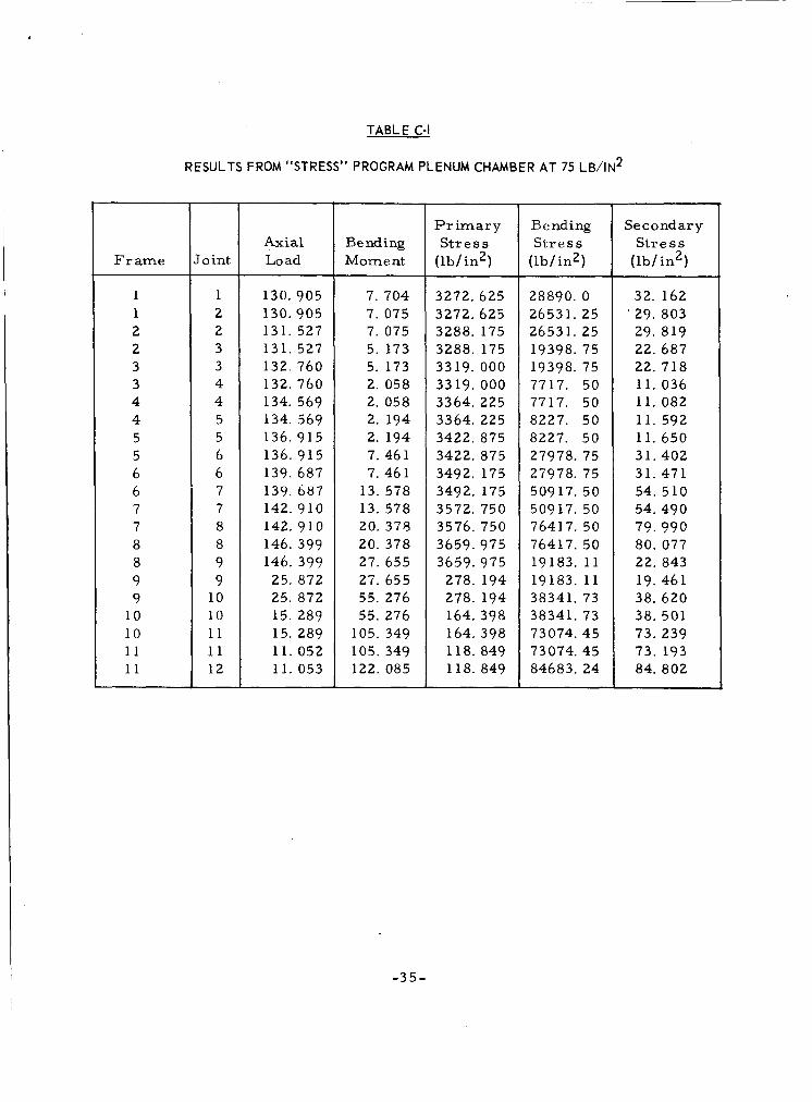
3 . Results of Computer Analysis a t Design Conditions
The model was evaluated on Avco Program STRESS, Memo A-3259, May 28, 1966, "Structure Plenum. " The resul ts a r e shown in Table C-I.
Maximum r i m a r y s t r e s s was 3660 lb/in?. Maximum secondary stress was
computed above. Furthermore, any axial bending will reduce the secondary stress in the f rames . s t r e s s components presented in Table C-I. Near tha chamber ends, the max- imum axial seconda,ry s t r e s s , due to the edge restraint , will be l e s s than twice
2 the maximum pr imary s t r e s s above, i. e . , l e s s than 7.3 klb/in.
84. 8 klb/in. 5 The axial s t r e s s i s on the order of one half the pr imary s t r e s s e s
Therefore, the s t r e s s intensities will not exceed the
-32-
,
I- I
- 3 3 -
0.093 ‘-wo MATERIAL : 304 SST
R =7.276 1 PRESSURE : 75 Ib/in2
A TEMP : 0 R = 2.044
a CROSS-SECTION VIEW
I I Ii2 :I
7 / -
NUMBERS
I /
PLATE ELEMENTS
9-11 AREA 0.04 inz. 0.093 in?
INERTIA 5.33X1G6in? 6.70Xld5in4
FRAME NUMBERS
X
b. PLANE FRAME MODEL
770813 D
Figure C-3. CROSS SECTION AND ANALYTICAL MODEL OF PLENUM CHAMBER
-34-
‘
Bending Mom e nt
7. 704 7. 075 7. 075 5. 173 5. 173 2. 058 2. 058 2. 194 2. 194 7.461 7. 461
13. 578 13. 578 20. 375 20. 378 27. 655 27. 655 55. 276 55. 276
105. 349 105. 349 122. 085
t
P r i m a r y S t r e s s
( 1 b / in2)
3272. 625 3272. 625 3288. 175 3288. 175 3319. 000 3319. 000 3364. 225 3364. 225 3422. 875 3422. 875 3492. 175 3492. 175 3572. 750 3576. 750 3659.975 3659.975
278. 194 278. 194 164. 398 164. 398 118. 849 118. 849
TABLE C-l
RESULTS FROM “STRESS” PROGRAM PLENUM CHAMBER AT 75 L B / I N ~
Frame ~~~
1 1 2 2 3 3 4 4 5 5 6 6 7 7 8 8 9 9
10 10 11 11
roint
1 2 2 3 3 4 4 5 5 6 6 7 7 8 8 9 9
10 10 11 11 12
Axial Lo ad
130.905 130.905 131. 527 131. 527 132. 760 132. 760 134. 569 134. 569 136. 915 136. 915 139. 687
142. 910 142. 910 146. 399 146. 399 25. 872 25. 872 15. 289 15. 289 11. 052 11. 053
139. 687
Bending S t r e s s
(lb/in2)
28890. 0 26531. 25 26531. 25 19398. 75 19398. 75 7717. 50 7717. 50 8227. 50 8227. 50 27978. 75 27978. 75 50917. 50 50917. 50 76417. 50 76417. 50 19183. 11 19183. 11 38341. 73 38341. 73 73074. 45 73074.45 84683. 24
Se c o nd ar y S t r e s s
( lb/ in2)
32. 162 ’ 29. 803 29. 819 22. 687 22. 718 11. 036 11. 082 11. 592 11. 650 31.402 31.471 54. 510 54. 490 79.990 80. 077 22. 843 19. 461 38. 620 38. 501 73. 239 73. 193 84. 802
-35-
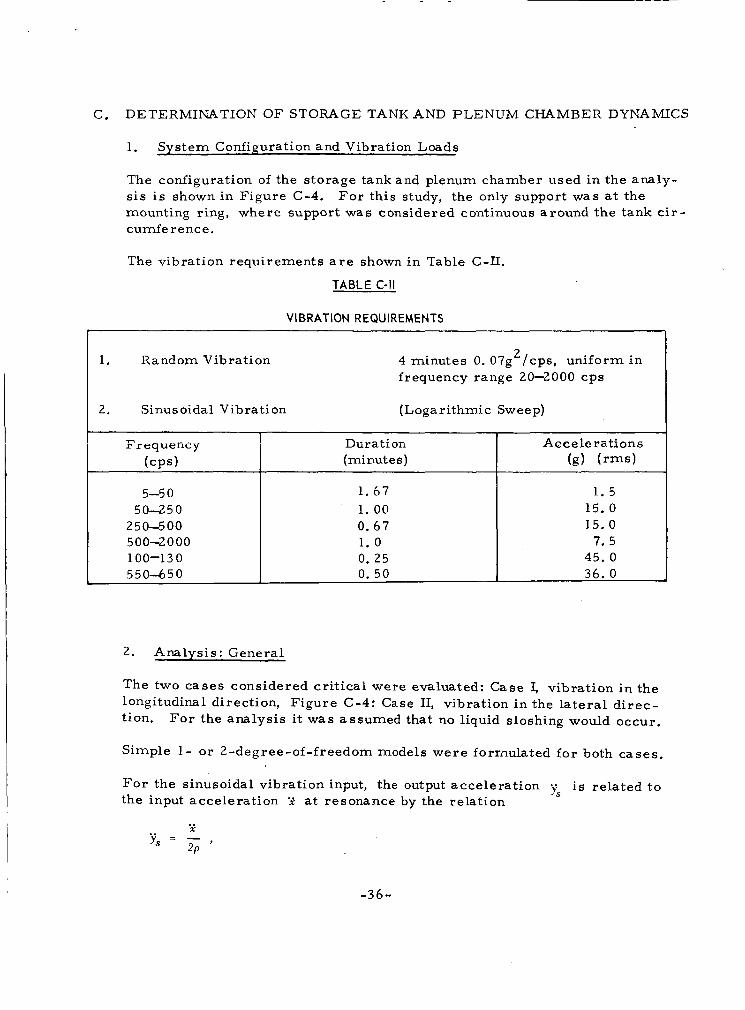
C. DETERMINATION OF STORAGE TANK AND PLENUM CHAMBER DYNAMICS
Frequency (CPS)
5-5 0 50-250
2 5 0-5 0 0 500-2000 100-130 550-650
1.
Dura ti m A ccele rations (mi nut e s ) (g) (rms)
1.67 1.5 1. 00 15. 0 0. 67 15. 0 1. 0 7. 5 0. 25 45.0 0. 50 36. 0
System Configuration and Vibration Loads
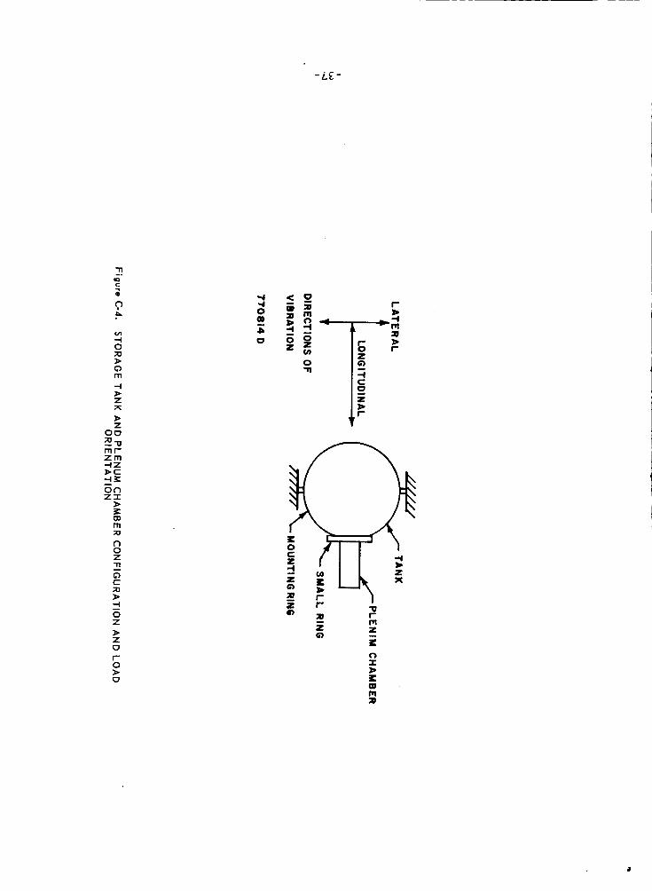
The configuration of the storage tankand plenum chamber used in the analy- s i s is shown in Figure C-4. mounting ring, where support was considered continuous around the tank c i r - cumfe rence.
F o r this study, the only support w a s at the
The vibration requirements a r e shown in Table C-LI.
TABLE C-ll
VIBRATION REQUIREMENTS
f 1, Random Vibration 2 4 minutes 0. 07g /cps, uniform in
frequency range 20-2000 cps
2. Analysis : General
The two cases considered critical were evaluated: Case I, vibration in the longitudinal direction, Figure C-4: Case 11, vibration in the la te ra l d i rec- tion. Fo r the analysis it was assumed that no liquid sloshing would occur.
Simple 1 - or 2-degree-of-freedom models were forrmdated for both cases .
F o r the sinusoidal vibration input, the output accelerat ion ys is related t o the input acceleration .; a t resonance by the relation
.. X ..
y s = - , 2P
-36-
n -. 10 C
i '? P
-4 * Z 7c * Z
00 Z1-0 r n r
n 0 z n
i 0 Z * Z 0 r 0 * 0
0 n
r b 4 m W B r
L
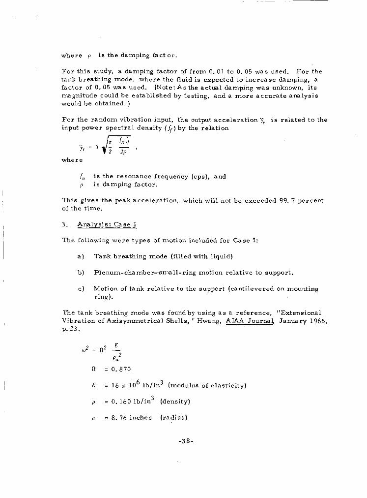
where p i s the damping fact or .
Fo r this study, a damping factor of f rom 0. 01 to 0. 05 was used. tank breathing mode, where the fluid i s expected t o increase damping, a factor of 0.05 w a s used. (Note: A s the actual damping was unknown, its magnitude could be established by testing, and a more accura te analysis would be obtained. )
F o r the
For the random vibration input, the output accelerat ion 'j; input power spectral density (4) by the relation
is related t o the
yr = 3 JI- - 2 2P '
where
f, p is damping factor.
is the resonance frequency (cps), and
This gives the peak acceleration, which will not be exceeded 99. 7 percent of the t ime.
3. Analysis: Case I
The following were types of motioil included for Case I:
a ) Tank breathing mode (filled with liquid)
b ) P1 enum- c ha mb e r-sm 11 - ring mot ion relative t o support.
c) Motion of tank relative to the support (cantilevered on mounting ring).
The tank breathing mode was foundby using a s a reference, "Extensional Vibration of Axisymmetrical Shells, Hwang, AIAA Journal, January 1965, p. 23.
E
Pa
"2 = - 2
C! = 0.870
E = 16 x 10 ' 6 lb/ in 3 (modulus of elasticity)
p = 0. 160 lb/in3 (density)
a = 8. 76 inches (radius)
-38-
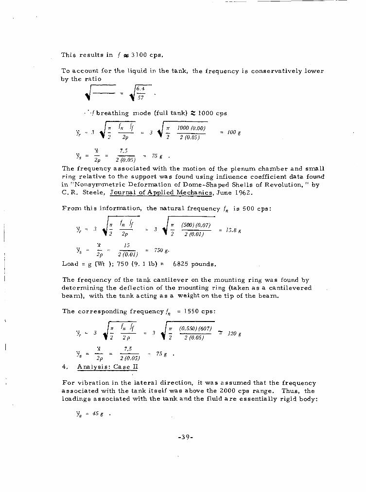
This resul ts in f 3100 cps.
I
To account for the liquid in the tank, the frequency i s conservatively lower by the rat io
'.f breathing mode (full tank) Z 1000 cps
1000 (0.00) =
2 2 (0.05) ..
X 7.5 .. .. = 7 5 g . ys = 2p = 2 (0.05)
The frequency associated with the motion of the plenum chamber and small ring relative to the support was found using influence coefficient data found in I 'Nonsymmetric Deformation of Dome-Shaped Shells of Revolution, I ' by C. R. Steele, Journal of Applied Mechanics, June 1962.
F r o m this information, the natural frequency f, is 500 cps: I I
(500) (0.07) = 15.8g
2 2 (0.01)
X 15 .. .. = 750 g. y s = - = - 2 p Z(0.01)
Load = g (Wt ) ; 750 (9. 1 lb) = 6825 pounds.
The frequency of the tank cantilever on the mounting ring was found by determining the deflection of the mounting ring (taken a s a cantilevered beam), with the tank acting as a weight on the t i p of the beam.
The corresponding frequency f, = 1550 cps:
.. y , = 3 J; - - 'n If = 4; (0.550) (607) z 1 2 o g 2 P 2 2 (0.05)
X 7.5 .. .. y, = - = - = 7 5 g . 2P 2 (0.05)
4. Analysis: Case I1
F o r vibration in the la te ra l direction, it was assumed that the frequency associated with the tank itself w a s above the 2000 cps range. Thus, the loadings associated with the tank and the fluid a r e essentially rigid body:
.. y, = 4 5 g .
- 3 9 -
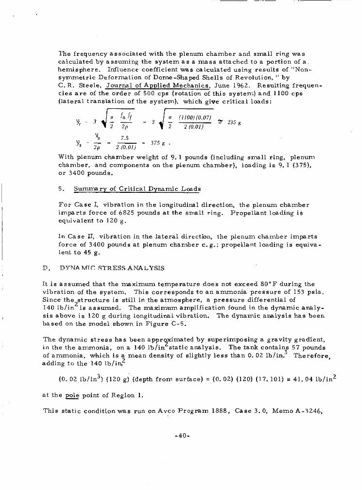
The frequency associated with the plenum chamber and small ring was calculated by assuming the system a s a m a s s attached to a portion of a . hemisphere. symmetr ic Deformation of Dome-Shaped Shells of Revolution, ' I by C. R . Steele, Journal of Applied Mechanics, June 1962. Resulting frequen- c ies a r e of the order of 500 cps (rotation of this system) and 1100 cps ( la teral translation of the system), which give cr i t ical loads:
Influence coefficient was calculated using resul ts of "Non-
17 (1100) (0.07) 235g ..
2 2P 2 2 (0.01)
With plenum chamber weight of 9. 1 pounds (including small ring, plenum chamber, and components on the plenum chamber), loading i s 9. 1 (375), o r 3400 pounds.
5. Summary of Crit ical Dynamic Loads
F o r Case I, vibration in the longitudinal direction, the plenum chamber imparts force of 6825 pounds a t the small ring. equivalent to 120 g.
Propellant loading is
In Case 11, vibration in the la teral direction, the plenum chamber impar t s force of 3400 pounds a t plenum chamber c . g.; propellant loading is equiva- lent t o 45 g.
z!. DTJNAMTC. STRESS ANALYSIS
It i s assumed that the maximum temperature does not exceed 80°F during the vibration of the system. Since the s t ruc ture is still in the atmosphere, a p re s su re differential of 140 lb / in i s assumed. sis above i s 120 g during longitudinal vibration. based on the model shown in Figure C-5.
This corresponds t o a n ammonia pressure of 153 psia.
The maximum amplification found in the dynamic analy- The dynamic analysis has been
2
The dynamic s t r e s s has been approximated by superimposing a gravity gradient, 2 i n the the ammonia, on a 140 lb / in s ta t ic analysis. The tank contains 57 pounds
of ammonia, which is a mean density of slightly l e s s than 0. 02 lb/in? Therefore, adding t o the 140 lb/ iq2
(0. 02 lb/in3) (120 g) (depth f rom surface) = (0. 02) (120) (17. 101) = 41. 04 lb/ in2
a t the pole point of Region 1.
This s ta t ic condition was run on Avco Program 1888, Case 3.0, Memo A-3246,
-40-

z 0 G K w -I w o 0 4 LL 0 2
t- o W
0
E (3 z K (3
t- z 3 0 I
-
E
-41 -
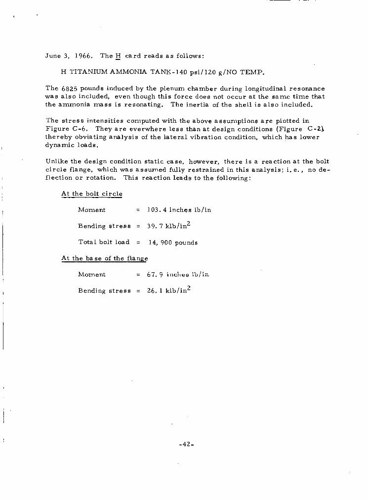
June 3, 1966. The - H card reads a s follows:
!
H TITANIUM AMMONIA TANK-149 ps i / l20 g/NO TEMP.
The 6825 pounds induced by the plenum chamber during longitudinal resonance was a l s o included, even though this force does not occur a t the same t ime that the ammonia m a s s is resonating. The inertia of the shell is a l s o included.
The s t r e s s intensit ies computed with the above assumptions a r e plotted in Figure C-6. thereby obviating analysis of the la te ra l vibration condition, which has lower dynamic loads.
They a r e everwhere l e s s than a t design conditions (Figure C-21
Unlike the design condition s ta t ic case, however, there is a reaction a t the bolt c i rc le flange, which was assumed fully restrained in this analysis ; i. e. , no de- flection o r rotation. This reaction leads to the following:
At the bolt c i rc le
Moment = 103. 4 inches lb/in
Bending stress = 39. 7 klb/in2
Total bolt load = 14, 900 pounds
At the base of the flange
Bending s t r e s s = 26. 1 klb/in2
-42-

!*q ‘ S S 3 Y l S
OD N
(D N
0
OD
t
N
Z 2
E Q 3 L
-43 -

DISTRIBUTION
Add r e s s e e
NASA/ Godda r d Space Flight Cent e r
Office of Director - - Code 100 Office of Assistant Director fo r SR -- Code 300 Office of Assistant Director of Projects - - Code 400 Office of Assistant Director of T&DS -- Code 500 Office of Assistant Director for Tech - - Code 700 L i b r a r y - - Code 252 Contracting Office - - Code 247 Technical Information Director - - Code 250 Technical Officer
Attn: W. Lund -- Code 734 (+1 reproducible)
Research Library - - Wilmington Research Library - - Lowell Reports Distribution Center - - Lowell
No. of Copies
10
1 1
41
-44 -