
FLIGHT PREPPING - insanerocketry.com€™s instructions to complete the engine prep-ping. Different...
8
1. Materials. I will use only lightweight, non-metal parts for the nose, body, and fins of my rocket. 2. Motors. I will use only certified, commercially-made model rocket motors, and will not tamper with these motors or use them for any purposes except those recommended by the manufacturer. 3. Ignition System. I will launch my rockets with an electrical launch system and electrical motor igniters. My launch system will have a safety interlock in series with the launch switch, and will use a launch switch that returns to the "off" position when released. 4. Misfires. If my rocket does not launch when I press the button of my electrical launch system, I will remove the launcher's safety inter- lock or disconnect its battery, and will wait 60 seconds after the last launch attempt before allowing anyone to approach the rocket. 5. Launch Safety. I will use a countdown before launch, and will en- sure that everyone is paying attention and is a safe distance of at least 15 feet away when I launch rockets with D motors or smaller, and 30 feet when I launch larger rockets. If I am uncertain about the safety or stability of an untested rocket, I will check the stability before flight and will fly it only after warning spectators and clearing them away to a safe distance. 6. Launcher. I will launch my rocket from a launch rod, tower, or rail that is pointed to within 30 degrees of the vertical to ensure that the rocket flies nearly straight up, and I will use a blast deflector to pre- vent the motor's exhaust from hitting the ground. To prevent acciden- tal eye injury, I will place launchers so that the end of the launch rod is above eye level or will cap the end of the rod when it is not in use. 7. Size. My model rocket will not weigh more than 1,500 grams (53 ounces) at liftoff and will not contain more than 125 grams (4.4 ounces) of propellant or 320 N-sec (71.9 pound-seconds) of total impulse. If my model rocket weighs more than one pound (453 grams) at liftoff or has more than four ounces (113 grams) of propellant, I will check and comply with Federal Aviation Administration regulations before flying. 8. Flight Safety. I will not launch my rocket at targets, into clouds, or near airplanes, and will not put any flammable or explosive payload in my rocket. 9. Launch Site. I will launch my rocket outdoors, in an open area at least as large as shown in the accompanying table, and in safe weather conditions with wind speeds no greater than 20 miles per hour. I will ensure that there is no dry grass close to the launch pad, and that the launch site does not present risk of grass fires. 10. Recovery System. I will use a recovery system such as a streamer or parachute in my rocket so that it returns safely and un- damaged and can be flown again, and I will use only flame-resistant or fireproof recovery system wadding in my rocket. 11. Recovery Safety. I will not attempt to recover my rocket from power lines, tall trees, or other dangerous places. LAUNCH SITE DIMENSIONS Installed Total Impulse (N-sec) Equivalent Motor Type Minimum Site Dimensions (ft.) 0.00 — 1.25 1/4A 50 1.26 — 2.50 A 100 2.51 — 5.00 B 200 10.01 — 20.00 D 500 20.01 — 40.00 E 1000 40.01 — 80.00 F 1000 80.01 — 160.00 G 1000 160.01 — 320.00 2 Gs 1500 5.01 — 10.00 C 400 Made in the U.S.A by Semroc Astronautics Corporation - Knightdale, N.C. 27545 LASER-X Kit No. KV-33 Specifications Body Diameter 1.340” (3.4cm) Length 21.5” (54.6cm) Fin Span 7.0” (17.8cm) Net Weight 1.8 oz. (49.9g) Engine Approx. Altitude A8-3 125’ B6-4 350’ C6-5 750’ FUTURISTIC SPACE PROBE GREAT DEMO BIRD FUN TO BUILD AND FLY FLYING MODEL ROCKET KIT PARACHUTE RECOVERY
-
Upload
truongminh -
Category
Documents
-
view
217 -
download
4
Transcript of FLIGHT PREPPING - insanerocketry.com€™s instructions to complete the engine prep-ping. Different...

1. Materials. I will use only lightweight, non-metal parts for the nose, body, and fins of my rocket.
2. Motors. I will use only certified, commercially-made model rocket motors, and will not tamper with these motors or use them for any purposes except those recommended by the manufacturer.
3. Ignition System. I will launch my rockets with an electrical launch system and electrical motor igniters. My launch system will have a safety interlock in series with the launch switch, and will use a launch switch that returns to the "off" position when released.
4. Misfires. If my rocket does not launch when I press the button of my electrical launch system, I will remove the launcher's safety inter-lock or disconnect its battery, and will wait 60 seconds after the last launch attempt before allowing anyone to approach the rocket.
5. Launch Safety. I will use a countdown before launch, and will en-sure that everyone is paying attention and is a safe distance of at least 15 feet away when I launch rockets with D motors or smaller, and 30 feet when I launch larger rockets. If I am uncertain about the safety or stability of an untested rocket, I will check the stability before flight and will fly it only after warning spectators and clearing them away to a safe distance.
6. Launcher. I will launch my rocket from a launch rod, tower, or rail that is pointed to within 30 degrees of the vertical to ensure that the rocket flies nearly straight up, and I will use a blast deflector to pre-vent the motor's exhaust from hitting the ground. To prevent acciden-tal eye injury, I will place launchers so that the end of the launch rod is above eye level or will cap the end of the rod when it is not in use.
7. Size. My model rocket will not weigh more than 1,500 grams (53 ounces) at liftoff and will not contain more than 125 grams (4.4 ounces) of propellant or 320 N-sec (71.9 pound-seconds) of total impulse. If my model rocket weighs more than one pound (453 grams) at liftoff or has more than four ounces (113 grams) of propellant, I will check and comply with Federal Aviation Administration regulations before flying.
8. Flight Safety. I will not launch my rocket at targets, into clouds, or near airplanes, and will not put any flammable or explosive payload in my rocket.
9. Launch Site. I will launch my rocket outdoors, in an open area at least as large as shown in the accompanying table, and in safe weather conditions with wind speeds no greater than 20 miles per hour. I will ensure that there is no dry grass close to the launch pad, and that the launch site does not present risk of grass fires.
10. Recovery System. I will use a recovery system such as a streamer or parachute in my rocket so that it returns safely and un-damaged and can be flown again, and I will use only flame-resistant or fireproof recovery system wadding in my rocket.
11. Recovery Safety. I will not attempt to recover my rocket from power lines, tall trees, or other dangerous places.
LAUNCH SITE DIMENSIONS
Installed Total Impulse (N-sec)
Equivalent Motor Type Minimum Site Dimensions (ft.)
0.00 — 1.25 1/4A 50
1.26 — 2.50 A 100
2.51 — 5.00 B 200
10.01 — 20.00 D 500
20.01 — 40.00 E 1000
40.01 — 80.00 F 1000
80.01 — 160.00 G 1000
160.01 — 320.00 2 Gs 1500
5.01 — 10.00 C 400
Made in the U.S.A by Semroc Astronautics Corporation - Knightdale, N.C. 27545
LASER-X Kit�No.�KV-33��������������������
Specifications Body Diameter 1.340” (3.4cm) Length 21.5” (54.6cm) Fin Span 7.0” (17.8cm) Net Weight 1.8 oz. (49.9g)
Engine Approx. Altitude A8-3 125’ B6-4 350’ C6-5 750’
FUTURISTIC SPACE PROBE
GREAT DEMO BIRD
FUN TO BUILD
AND FLY
FLYING MODEL ROCKET KIT
PARACHUTE RECOVERY

What is a @? A @ is a retro reproduction of an out-of-production model rocket kit. It is a close approxima-tion of a full scale model of an early historically sig-nificant model rocket kit from one of the many com-panies that pioneered the hobby over the past half century. A @ is not a true clone or identi-cal copy of the original. It incorporates improve-ments using modern technology, while keeping the flavor and build appeal of the early kits.
Copyright © 2003 Semroc Astronautics Corporation Box 1271 Knightdale, NC 27545 (919) 266-1977
About Centuri Engineering Company
Centuri Engineering Company was started in 1961 by Leroy (Lee) Piester in his garage while he was still in college in Phoenix, Arizona. With his wife, Betty, they built Centuri into one of the largest model rocket companies ever. Centuri was known for its unusual and innovative designs, producing over 140 different kits with something for every model rocketeer. They also produced model rocket engines and pioneered the modern composite high powered engines with their Enerjet line. Centuri Engineering was sold to Damon in the late 1960’s and shared the same parent corporation with Estes Industries, the largest model rocket com-pany in the world. The Centuri product line was kept separate from the Estes line until 1983. A few of the old kits have been reissued by Estes since then, but for the most part, Centuri Engineering Company lives today only in the dreams of the sen-ior members of the model rocket community.
November 25,2003
If you are not 100% satisfied with your Semroc product, we will make it right by providing what-ever you consider fair, from refund to replacement.
Contact us at:
Semroc Astronautics Corporation Customer Service Department P.O. Box 1271 Knightdale, North Carolina 27545
100% SATISFACTION GUARANTEE
LIMITATION OF LIABILITY Model rockets are not toys, but are functional rock-ets made of lightweight materials and are launched with NAR or Tripoli safety certified model rocket motors, electrically ignited and flown in accordance with the NAR Model Rocket Safety Code. If mis-used, model rockets can cause serious injury and property damage. Semroc certifies that it has exer-cised reasonable diligence in the design and manu-facture of its products. Semroc cannot assume any liability for the storage, transportation, or usage of its products. Semroc shall not be held responsible for any personal injury or property damage whatso-ever arising out of the handling, storage, use, or misuse of our products. The buyer assumes all risks and liabilities therefrom and accepts and uses Sem-roc products on these conditions. Your purchase and use of any Semroc products is construed as your agreement to and acceptance of these terms. If you do not agree to these terms and conditions, you must return the product, unused, for refund or credit.
JOIN THE NAR! Sign up online at www.nar.org to join the premier model rocketry organiza-tion. Semroc fully supports the Na-tional Association of Rocketry and rec-ognizes it as the sport’s official voice. The NAR is the oldest and largest sport rocketry organization in the world. Since 1957 over 80,000 serious sport rocket modelers have joined the NAR to take advantage of the fun and excitement of organized rocketry. It is always more fun if you fly with friends. The Sport Rocketry magazine is one of the best ways to keep informed of new developments in the hobby. Check online at www.semroc.com/nar for promotions just for NAR members.

FLIGHT PREPPING 29. Mounting the engine: Insert the engine
and make sure the engine hook keeps the engine in snugly. The hook may be slightly bent to make sure the engine is retained.
32. Refer to the model rocket engine manu-facturer’s instructions to complete the engine prep-ping. Different engines have different igniters and methods of hooking them up to the launch control-lers.
33. Carefully check all parts of your rocket before each flight as a part of your pre-flight check-list. Launch the Laser-X from a 1/8” diameter by 36” long launch rod.
30. Pack the recovery wadding from the top of the body tube. Use a sufficient quantity to protect the parachute, but not too much that there is no room left.
31. Fold the parachute and pack it and the shock cord on top of the recovery wadding. Slide the adapter into place, making sure it does not pinch the shock cord or parachute.
28. After the paint has dried, decals should be applied. The decals supplied with the Laser-X are waterslide decals. Each decal should be cut separately from the sheet. Apply each decal before starting the next. Think about where you want to apply each decal and check for fit before wetting the decal. There is no set place for each decal. Use your imagination.
TOOLS: In addition to the parts supplied, you will need the following tools to assemble and finish this kit.
About the Laser-X The Laser-X was initially released in 1968 in the American Rocketeer, but did not make it into the 1968 catalog released later in the year. It was the first in a series of kits incorporating all die-cut parts. Its large size and futuristic appearance made it a great rocket for small fields and demonstration launches. Reminiscent of the Estes Mars Snooper, the Laser-X became one of Centuri’s most famous kits. The original had a BC-54 balsa nose cone, but later models were migrated to plastic nose cones. The Laser-X was Centuri #KC-50 and was intro-duced with a price of $2.75. The @ Laser-X is updated by using laser-cut fins. The original balsa nose cone and body tube sizes are used. The parachute is smaller to re-duce drift during recovery. The original rubber shock cord is replaced with an elastic cord for longer life. The original method of attaching the shock cord has been replaced by a Kevlar® cord for greater reliability.
BEFORE YOU START! Make sure you have all the parts included in this kit that are listed in the Parts List in the center of these instructions. In addition to the parts included in this kit, you will also need the tools and materials listed below. Read the entire instructions before begin-ning to assemble your rocket. When you are thor-oughly familiar with these instructions, begin con-struction. Read each step and study the accompa-nying drawings. Check off each step as it is com-pleted. In each step, test-fit the parts together be-fore applying any glue. It is sometimes necessary to sand lightly or build-up some parts to obtain a precision fit. If you are uncertain of the location of some parts, refer to the exploded view in the cen-ter of these instructions. It is important that you always ensure that you have adequate glue joints.

1. These instructions are presented in a logical order to help you put your Laser-X together quickly and efficiently. Check off each step as you complete it and enjoy putting this kit together.
3. Lightly sand each side of the laser-cut fins. Carefully push the laser-cut fins from their sheet. Start at one point on each fin and slowly and gently work around the fin.
4. Stack all the fins in groups of four fins each. Line each group up squarely and sand the fins back and forth over some fine sandpaper to get rid of the hold-in tabs as shown below.
ASSEMBLY
2. There are many different balsa fin parts. Use the guide below to identify the parts that are called out in these instructions. There are two iden-tical sheets of laser-cut balsa.
25. When the fillets have dried, prepare balsa surfaces for a smooth professional looking finish. Fill the wood grain with balsa fillercoat or sanding sealer, When dry, sand with fine sandpaper. Repeat until smooth.
FINISHING
26. After all balsa surfaces have been pre-pared, wipe off all balsa dust with a dry cloth. First spray the model with an enamel primer. Choose a high visibility color combination like white and red for the final color.
27. Spray painting your model with a fast-drying enamel will produce the best results. PA-TIENCE…is the most important ingredient. Use sev-eral thin coats, allowing each coat to completely dry before the next coat. Start each spray a few inches above the model and end a few inches below the model. Keep the can about 12” away and use quick light coats. The final coat can be a little heavier to give the model a glossy wet-looking finish.

22. CAUTION: If small children are likely to come in contact with the finished rocket, skip this step. Slightly round the ends of the fin spikes with sandpaper. This will make the rocket safer to han-dle. Glue the spikes on the tips of each of the main fins. Leave 3/8” overhang at the rear of each fin.
24. Assemble chute using instructions printed on canopy. Tie chute and free end of elastic cord to loop on upper stage coupler.
23. Prepare the shock cord as follows. Line up one end of the elastic shock cord with the free end of the Kevlar cord extending from the top of the body tube. Tie an overhand knot at the end of the two cords. Pull the knot tight and place a small drop of white glue on the knot to prevent it from loosen-ing.
6. Repeat for all eight sets of main and upper fins. Round leading and trailing edges. Leave the tip and root edges flat.
7. Stand each body tube on the fin guide be-low and make the fin position marks on the sides of each tube. Find a convenient channel or groove such as a partially open drawer, a door jamb (as shown,) or a piece of molding. Using the channel, extend the marks the full length of the tube to pro-vide lines for aligning the fins.
5. Glue each main and upper fin to its exten-sion as shown in the diagram. Use a ruler to align the two parts along the root edges. Wax paper will prevent parts from sticking to your workspace..
8. Carefully punch out the two laser-cut cen-tering rings with the large center holes. Glue one on each end of one of the large coupler tubes. Set this motor mount assembly aside to dry.
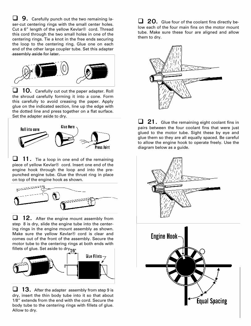
11. Tie a loop in one end of the remaining piece of yellow Kevlar® cord. Insert one end of the engine hook through the loop and into the pre-punched engine tube. Glue the thrust ring in place on top of the engine hook as shown.
9. Carefully punch out the two remaining la-ser-cut centering rings with the small center holes. Cut a 6” length of the yellow Kevlar® cord. Thread this cord through the two small holes in one of the centering rings. Tie a knot in the free ends securing the loop to the centering ring. Glue one on each end of the other large coupler tube. Set this adapter assembly aside for later.
10. Carefully cut out the paper adapter. Roll the shroud carefully forming it into a cone. Form this carefully to avoid creasing the paper. Apply glue on the indicated section, line up the edge with the dotted line and press together on a flat surface. Set the adapter aside to dry.
13. After the adapter assembly from step 9 is dry, insert the thin body tube into it so that about 1/8” extends from the end with the cord. Secure the body tube to the centering rings with fillets of glue. Allow to dry.
12. After the engine mount assembly from step 8 is dry, slide the engine tube into the center-ing rings in the engine mount assembly as shown. Make sure the yellow Kevlar® cord is clear and comes out of the front of the assembly. Secure the motor tube to the centering rings at both ends with fillets of glue. Set aside to dry.
20. Glue four of the coolant fins directly be-low each of the four main fins on the motor mount tube. Make sure these four are aligned and allow them to dry.
21. Glue the remaining eight coolant fins in pairs between the four coolant fins that were just glued to the motor tube. Sight these by eye and glue them so they are all equally spaced. Be careful to allow the engine hook to operate freely. Use the diagram below as a guide.

17. Run a thin bead of glue along the root edge of one of the fin assemblies. Attach it to the body tube on one of the lines drawn earlier. Re-move the fin and wait a few minutes until the glue gets tacky. Reapply the fin and check for proper alignment. Repeat for the other seven fin assem-blies on the main and upper body tubes. The main fins should be flush with the end of the body tube and the upper fins should be flush with the edge of the shroud.
18. After all fins are glued and properly aligned, stand both tubes upright and allow the glue to dry. When all the fin joints are dry, run a fillet of glue along each fin-body tube joint. Use your finger to spread the glue and form a smooth fillet at each joint.
19. Glue the launch lug midway between two of the main fins and flush with the bottom of the tube.
14. Slide the cone over the small body tube and over the edge of the adapter assembly. The rear edge should be slightly larger than the coupler, so its diameter will match the main body tube. Mark where the cone edges touch the body tube. Remove the cone and apply a bead of glue where the cone intersected the body tube. Reapply the cone and make sure the glue will secure the cone to both the body tube and the coupler.
15. Insert the nose cone in the small body tube and check for fit. A small amount of sanding may be necessary. Apply a small bead of glue in-side the top end of the small body tube. Insert the balsa nose cone into the tube and make sure it is seated properly.
16. Check the engine mount for fit in the large body tube. If it has rough edges or excessive glue, sand lightly until it fits into the body tube. Ap-ply a heavy bead around the inside of the main tube. Insert the yellow cord first and let it fall through the tube. Then quickly and smoothly push the motor mount into the tube until the end of the motor mount is flush with the end of the body tube. Position the motor mount so the engine hook is just to one side of one of the marks on the outside of the main body tube as in the diagram below.

Parts List A 1 Body Tube .......................... ST-5120 B 1 Body Tube ........................... ST-1380 C 1 Body Tube ........................... ST-730E D 1 Balsa Nose Cone ................. BC-524 E 1 Laser Cut Fin Set ................. FV-33 F 2 Tubing Couplers.................. HTC-13 G 2 Centering Rings................... CR-713 H 2 Centering Rings................... CR-513 I 1 Thrust Ring ......................... TR-7 J 1 Launch Lug.......................... LL-122 K 1 Engine Hook ....................... EH-28 L 1 Elastic Cord......................... EC-124 M 1 Kevlar® Thread .................. SCK-24 N 1 Plastic Parachute ............... RC-12 O 1 Tape Discs ........................... TD-6 P 1 Shroud Line......................... SLT-6 Q 4 Wood Dowels...................... WD-230 R 1 Decal.................................... DKV-33 S 1 Shroud ................................ IKV-33S
EXPLODED VIEW


![Detonators, Igniters, Primers, And Other Initiating Devices[1]](https://static.fdocuments.in/doc/165x107/543cbed5b1af9fc02e8b4772/detonators-igniters-primers-and-other-initiating-devices1.jpg)