Flight Hardware Development of Colloid Microthruster...
13
The 30 th International Electric Propulsion Conference, Florence, Italy September 17-20, 2007 1 Flight Hardware Development of Colloid Microthruster Technology for the Space Technology 7 and LISA Missions IEPC-2007-288 Presented at the 30 th International Electric Propulsion Conference, Florence, Italy September 17-20, 2007 John K. Ziemer * , Thomas M. Randolph, and Manuel Gamero-Castaño † Jet Propulsion Laboratory, California Institute of Technology, Pasadena, CA 91109 Vlad Hruby ‡ , William Connolly, Nathaniel Demmons, Eric Ehrbar, Roy Martin, Tom Roy, Douglas Spence, Jurg Zwahlen Busek Co., Natick, MA 01760 The NASA New Millennium Program is planning a flight demonstration of Colloid Micro-Newton Thruster (CMNT) technology on the Space Technology 7 (ST7) mission for future applications to precision formation flying missions such as the Laser Interferometer Space Antenna (LISA) mission. Colloid microthrusters are the actuators for the disturbance reduction system (DRS) on the ESA LISA Pathfinder spacecraft along with FEEP microthrusters as part of the ESA LISA Technology Package (LTP). The goal of the ST7 mission is to demonstrate the technologies necessary to meet the nanometer-level precision positioning control requirements of the LISA mission. To achieve this goal, two CMNT clusters with four thrusters each are required to provide thrust resolution <0.1 μN and thrust noise <0.1 μN/!Hz for thrust levels between 5 and 30 μN. Developed by Busek Co. Inc., with support from JPL in testing and design, the CMNT has been developed over the last five years into a flight-ready microthruster system. The development, validation testing, and flight unit production of the CMNTs are described. Development and validation testing has included a single-thruster system level 3400-hour test, propellant and materials compatibility testing, flight cluster-level vibration and thermal vacuum testing, and performance verification tests. Flight unit production of two clusters was completed in February of 2007 with environmental qualification tests immediately following. Currently both units are being reassembled to replace materials found to be incompatible with the propellant at high temperature before qualification tests are repeated. Final delivery of the units is planned for early 2008 with a planned launch and flight demonstration in 2010. I Introduction ecent interest in high resolution space interferometers, such as the Laser Interferometer Space Antenna (LISA), that require precise position control has created an interest for developing precise, low-thrust propulsion technology. The primary objective of LISA is to detect and measure as yet unobserved gravitational waves produced by compact binary systems and mergers of super massive black holes. However, even interplanetary space is subject to minute disturbances, such as solar wind, radiation, and photon pressure that could mask the influence of gravitational waves on free-floating proof masses. To shield the gravitational wave instrument, LISA consists of a precisely controlled set of spacecraft that follows the array proof masses within approximately 10 nm and provide a disturbance free environment. Calculations have shown that to reach the sensitivity level of interest, the disturbances to the proof masses can be no more than 3!10 -15 m s -2 Hz -1/2 in the 3x10 -5 to 1 Hz bandwidth 1 . * Senior Engineer, Electric Propulsion Group, Jet Propulsion Laboratory, 4800 Oak Grove Drive, M/S 125-109, Pasadena, CA, 91109; [email protected] † Currently an Assistant Professor at the University of California, Irvine, CA 92697; [email protected] ‡ President, Busek Company, 11 Tech Circle, Natick, MA 01760; [email protected] R
-
Upload
phungkhuong -
Category
Documents
-
view
221 -
download
3
Transcript of Flight Hardware Development of Colloid Microthruster...

The 30th
International Electric Propulsion Conference, Florence, Italy
September 17-20, 2007
1
Flight Hardware Development of Colloid Microthruster
Technology for the Space Technology 7 and LISA Missions
IEPC-2007-288
Presented at the 30th
International Electric Propulsion Conference, Florence, Italy
September 17-20, 2007
John K. Ziemer*, Thomas M. Randolph, and Manuel Gamero-Castaño
†
Jet Propulsion Laboratory, California Institute of Technology, Pasadena, CA 91109
Vlad Hruby‡, William Connolly, Nathaniel Demmons, Eric Ehrbar, Roy Martin, Tom Roy,
Douglas Spence, Jurg Zwahlen
Busek Co., Natick, MA 01760
The NASA New Millennium Program is planning a flight demonstration of Colloid
Micro-Newton Thruster (CMNT) technology on the Space Technology 7 (ST7) mission for
future applications to precision formation flying missions such as the Laser Interferometer
Space Antenna (LISA) mission. Colloid microthrusters are the actuators for the disturbance
reduction system (DRS) on the ESA LISA Pathfinder spacecraft along with FEEP
microthrusters as part of the ESA LISA Technology Package (LTP). The goal of the ST7
mission is to demonstrate the technologies necessary to meet the nanometer-level precision
positioning control requirements of the LISA mission. To achieve this goal, two CMNT
clusters with four thrusters each are required to provide thrust resolution <0.1 µN and
thrust noise <0.1 µN/!Hz for thrust levels between 5 and 30 µN. Developed by Busek Co.
Inc., with support from JPL in testing and design, the CMNT has been developed over the
last five years into a flight-ready microthruster system. The development, validation testing,
and flight unit production of the CMNTs are described. Development and validation testing
has included a single-thruster system level 3400-hour test, propellant and materials
compatibility testing, flight cluster-level vibration and thermal vacuum testing, and
performance verification tests. Flight unit production of two clusters was completed in
February of 2007 with environmental qualification tests immediately following. Currently
both units are being reassembled to replace materials found to be incompatible with the
propellant at high temperature before qualification tests are repeated. Final delivery of the
units is planned for early 2008 with a planned launch and flight demonstration in 2010.
I Introduction
ecent interest in high resolution space interferometers, such as the Laser Interferometer Space Antenna (LISA),
that require precise position control has created an interest for developing precise, low-thrust propulsion
technology. The primary objective of LISA is to detect and measure as yet unobserved gravitational waves
produced by compact binary systems and mergers of super massive black holes. However, even interplanetary
space is subject to minute disturbances, such as solar wind, radiation, and photon pressure that could mask the
influence of gravitational waves on free-floating proof masses. To shield the gravitational wave instrument, LISA
consists of a precisely controlled set of spacecraft that follows the array proof masses within approximately 10 nm
and provide a disturbance free environment. Calculations have shown that to reach the sensitivity level of interest,
the disturbances to the proof masses can be no more than 3!10-15
m s-2
Hz-1/2
in the 3x10⁻⁵
to 1 Hz bandwidth1.
* Senior Engineer, Electric Propulsion Group, Jet Propulsion Laboratory, 4800 Oak Grove Drive, M/S 125-109,
Pasadena, CA, 91109; [email protected] † Currently an Assistant Professor at the University of California, Irvine, CA 92697; [email protected]
‡ President, Busek Company, 11 Tech Circle, Natick, MA 01760; [email protected]
R
The 30th
International Electric Propulsion Conference, Florence, Italy
September 17-20, 2007
2
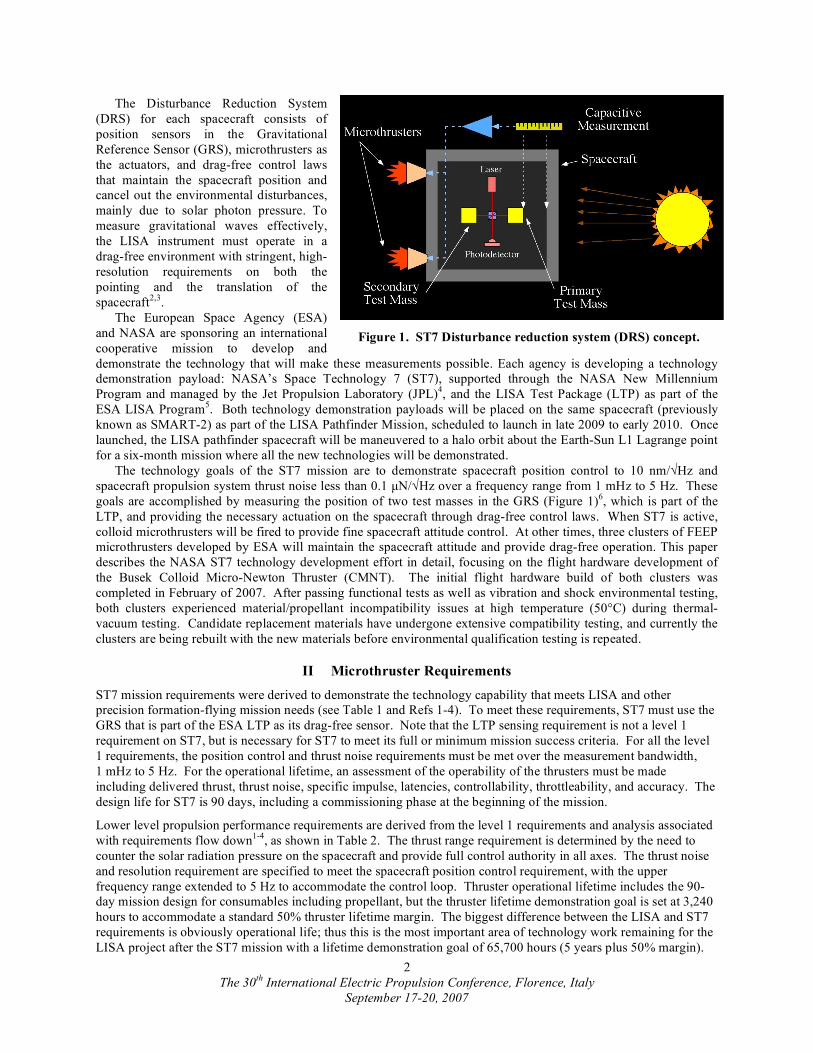
The Disturbance Reduction System
(DRS) for each spacecraft consists of
position sensors in the Gravitational
Reference Sensor (GRS), microthrusters as
the actuators, and drag-free control laws
that maintain the spacecraft position and
cancel out the environmental disturbances,
mainly due to solar photon pressure. To
measure gravitational waves effectively,
the LISA instrument must operate in a
drag-free environment with stringent, high-
resolution requirements on both the
pointing and the translation of the
spacecraft2,3
.
The European Space Agency (ESA)
and NASA are sponsoring an international
cooperative mission to develop and
demonstrate the technology that will make these measurements possible. Each agency is developing a technology
demonstration payload: NASA’s Space Technology 7 (ST7), supported through the NASA New Millennium
Program and managed by the Jet Propulsion Laboratory (JPL)4, and the LISA Test Package (LTP) as part of the
ESA LISA Program5. Both technology demonstration payloads will be placed on the same spacecraft (previously
known as SMART-2) as part of the LISA Pathfinder Mission, scheduled to launch in late 2009 to early 2010. Once
launched, the LISA pathfinder spacecraft will be maneuvered to a halo orbit about the Earth-Sun L1 Lagrange point
for a six-month mission where all the new technologies will be demonstrated.
The technology goals of the ST7 mission are to demonstrate spacecraft position control to 10 nm/!Hz and
spacecraft propulsion system thrust noise less than 0.1 µN/!Hz over a frequency range from 1 mHz to 5 Hz. These
goals are accomplished by measuring the position of two test masses in the GRS (Figure 1)6, which is part of the
LTP, and providing the necessary actuation on the spacecraft through drag-free control laws. When ST7 is active,
colloid microthrusters will be fired to provide fine spacecraft attitude control. At other times, three clusters of FEEP
microthrusters developed by ESA will maintain the spacecraft attitude and provide drag-free operation. This paper
describes the NASA ST7 technology development effort in detail, focusing on the flight hardware development of
the Busek Colloid Micro-Newton Thruster (CMNT). The initial flight hardware build of both clusters was
completed in February of 2007. After passing functional tests as well as vibration and shock environmental testing,
both clusters experienced material/propellant incompatibility issues at high temperature (50°C) during thermal-
vacuum testing. Candidate replacement materials have undergone extensive compatibility testing, and currently the
clusters are being rebuilt with the new materials before environmental qualification testing is repeated.
II Microthruster Requirements
ST7 mission requirements were derived to demonstrate the technology capability that meets LISA and other
precision formation-flying mission needs (see Table 1 and Refs 1-4). To meet these requirements, ST7 must use the
GRS that is part of the ESA LTP as its drag-free sensor. Note that the LTP sensing requirement is not a level 1
requirement on ST7, but is necessary for ST7 to meet its full or minimum mission success criteria. For all the level
1 requirements, the position control and thrust noise requirements must be met over the measurement bandwidth,
1 mHz to 5 Hz. For the operational lifetime, an assessment of the operability of the thrusters must be made
including delivered thrust, thrust noise, specific impulse, latencies, controllability, throttleability, and accuracy. The
design life for ST7 is 90 days, including a commissioning phase at the beginning of the mission.
Lower level propulsion performance requirements are derived from the level 1 requirements and analysis associated
with requirements flow down1-4
, as shown in Table 2. The thrust range requirement is determined by the need to
counter the solar radiation pressure on the spacecraft and provide full control authority in all axes. The thrust noise
and resolution requirement are specified to meet the spacecraft position control requirement, with the upper
frequency range extended to 5 Hz to accommodate the control loop. Thruster operational lifetime includes the 90-
day mission design for consumables including propellant, but the thruster lifetime demonstration goal is set at 3,240
hours to accommodate a standard 50% thruster lifetime margin. The biggest difference between the LISA and ST7
requirements is obviously operational life; thus this is the most important area of technology work remaining for the
LISA project after the ST7 mission with a lifetime demonstration goal of 65,700 hours (5 years plus 50% margin).
Figure 1. ST7 Disturbance reduction system (DRS) concept.
The 30th
International Electric Propulsion Conference, Florence, Italy
September 17-20, 2007
3
Table 1. ST7 level 1 requirements including full and minimum success criteria. See References 1-4.
Technology Requirement Full Success Criteria Minimum Success Criteria
LTP Sensing Noise < 5 nm/!Hz < 50 nm/!Hz
Spacecraft Position Control < 10 nm/!Hz < 100 nm/!Hz
Thrust Noise < 0.1 µN/!Hz < 0.5 µN/!Hz
Control Life > 60 days > 10 days
Table 2. Derived ST7 and LISA microthruster propulsion requirements. See References 1-4.
Requirement ST7 LISA
Thrust Range 5 to 30 µN 5 to 30 µN*
Thrust Precision < 0.1 µN < 0.1 µN
Thrust Noise < 0.1 µN/!Hz (5 Hz control loop) < 0.1 µN/!Hz (5 Hz control loop)
Measurement Bandwidth 1x10⁻³ to 5 Hz 3x10
-5 to 1 Hz
Thrust Command Rate 10 Hz (< 0.1 s latency) TBD
Thrust Range Response Time < 100 s TBD
Specific Impulse > 150 s TBD
Operational Lifetime > 2,160 hours (90 days) > 43,800 hours (5 years)†
Plume Half Angle < 35º (95% beam current) TBD
* The LISA thrust range requirement may be lower for the science phase and higher for tip-off recovery †
The LISA mission has an operational goal of 10 years that will require an additional 3.5 years worth of consumables
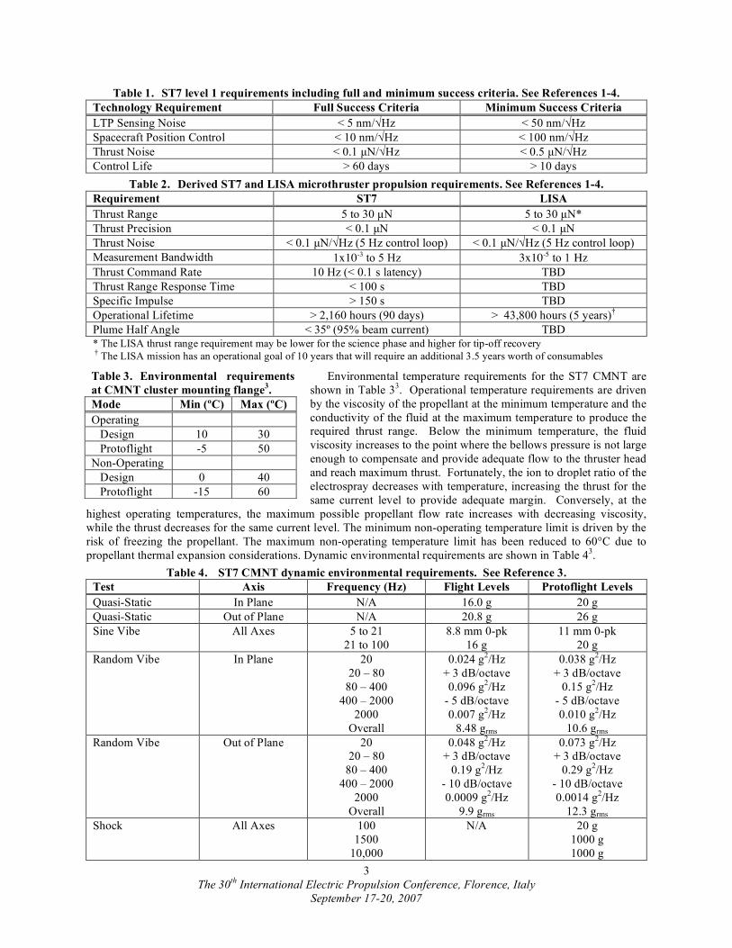
Environmental temperature requirements for the ST7 CMNT are
shown in Table 33. Operational temperature requirements are driven
by the viscosity of the propellant at the minimum temperature and the
conductivity of the fluid at the maximum temperature to produce the
required thrust range. Below the minimum temperature, the fluid
viscosity increases to the point where the bellows pressure is not large
enough to compensate and provide adequate flow to the thruster head
and reach maximum thrust. Fortunately, the ion to droplet ratio of the
electrospray decreases with temperature, increasing the thrust for the
same current level to provide adequate margin. Conversely, at the
highest operating temperatures, the maximum possible propellant flow rate increases with decreasing viscosity,
while the thrust decreases for the same current level. The minimum non-operating temperature limit is driven by the
risk of freezing the propellant. The maximum non-operating temperature limit has been reduced to 60°C due to
propellant thermal expansion considerations. Dynamic environmental requirements are shown in Table 43.
Table 4. ST7 CMNT dynamic environmental requirements. See Reference 3.
Test Axis Frequency (Hz) Flight Levels Protoflight Levels
Quasi-Static In Plane N/A 16.0 g 20 g
Quasi-Static Out of Plane N/A 20.8 g 26 g
Sine Vibe All Axes 5 to 21
21 to 100
8.8 mm 0-pk
16 g
11 mm 0-pk
20 g
Random Vibe In Plane 20
20 – 80
80 – 400
400 – 2000
2000
Overall
0.024 g2/Hz
+ 3 dB/octave
0.096 g2/Hz
- 5 dB/octave
0.007 g2/Hz
8.48 grms
0.038 g2/Hz
+ 3 dB/octave
0.15 g2/Hz
- 5 dB/octave
0.010 g2/Hz
10.6 grms
Random Vibe Out of Plane 20
20 – 80
80 – 400
400 – 2000
2000
Overall
0.048 g2/Hz
+ 3 dB/octave
0.19 g2/Hz
- 10 dB/octave
0.0009 g2/Hz
9.9 grms
0.073 g2/Hz
+ 3 dB/octave
0.29 g2/Hz
- 10 dB/octave
0.0014 g2/Hz
12.3 grms
Shock All Axes 100
1500
10,000
N/A 20 g
1000 g
1000 g
Table 3. Environmental requirements
at CMNT cluster mounting flange3.
Mode Min (ºC) Max (ºC)
Operating
Design 10 30
Protoflight -5 50
Non-Operating
Design 0 40
Protoflight -15 60
The 30th
International Electric Propulsion Conference, Florence, Italy
September 17-20, 2007
4
III CMNT Technology Development
The two Colloid Micro-Newton Thruster (CMNT)
clusters being developed at Busek Co., Inc.2,3,7,8
each
include four complete and independent thruster
subsystems: 4 thruster heads, 4 propellant storage and
feed control (microvalve) systems, 1 cathode
neutralizer, 4 PPUs and 1 DCIU. Thrust is adjustable
from 5-30 µN by changing the beam voltage (2-10 kV)
and/or propellant flow rate that determines the beam
current (2.2-5.4 µA)§. Independent, fine control of both
the beam current and beam voltage allow for precise
control of thrust to better than 0.1 µN resolution with
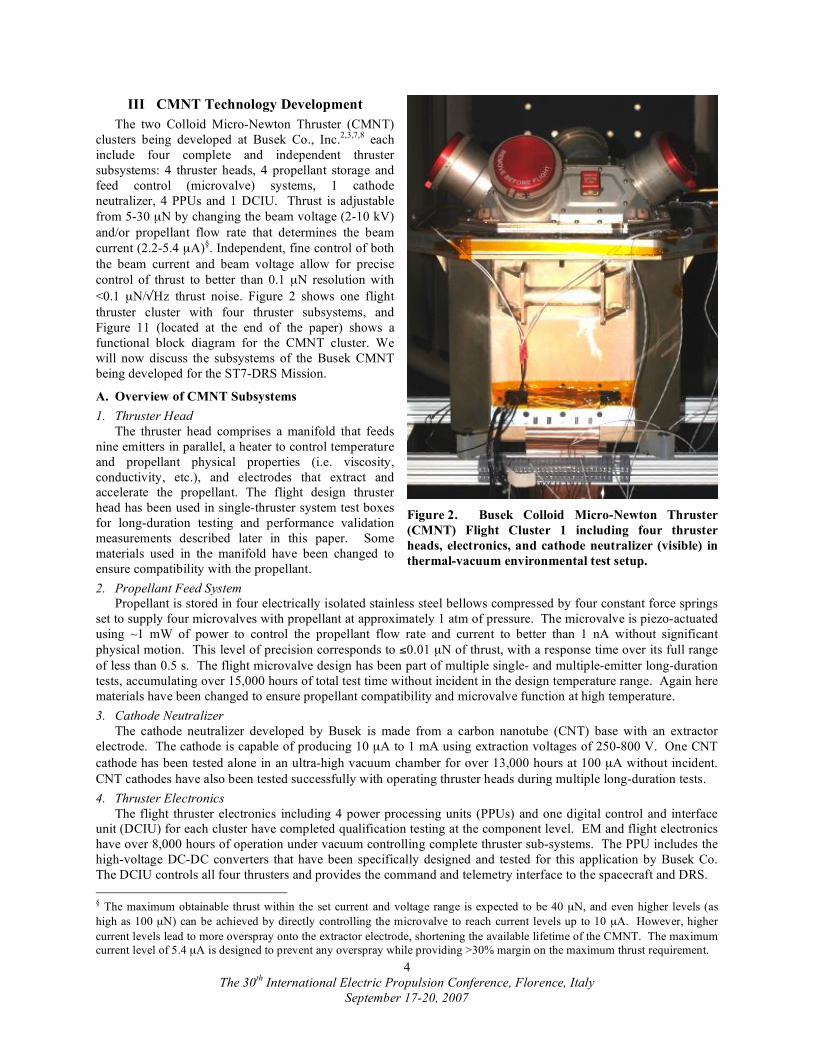
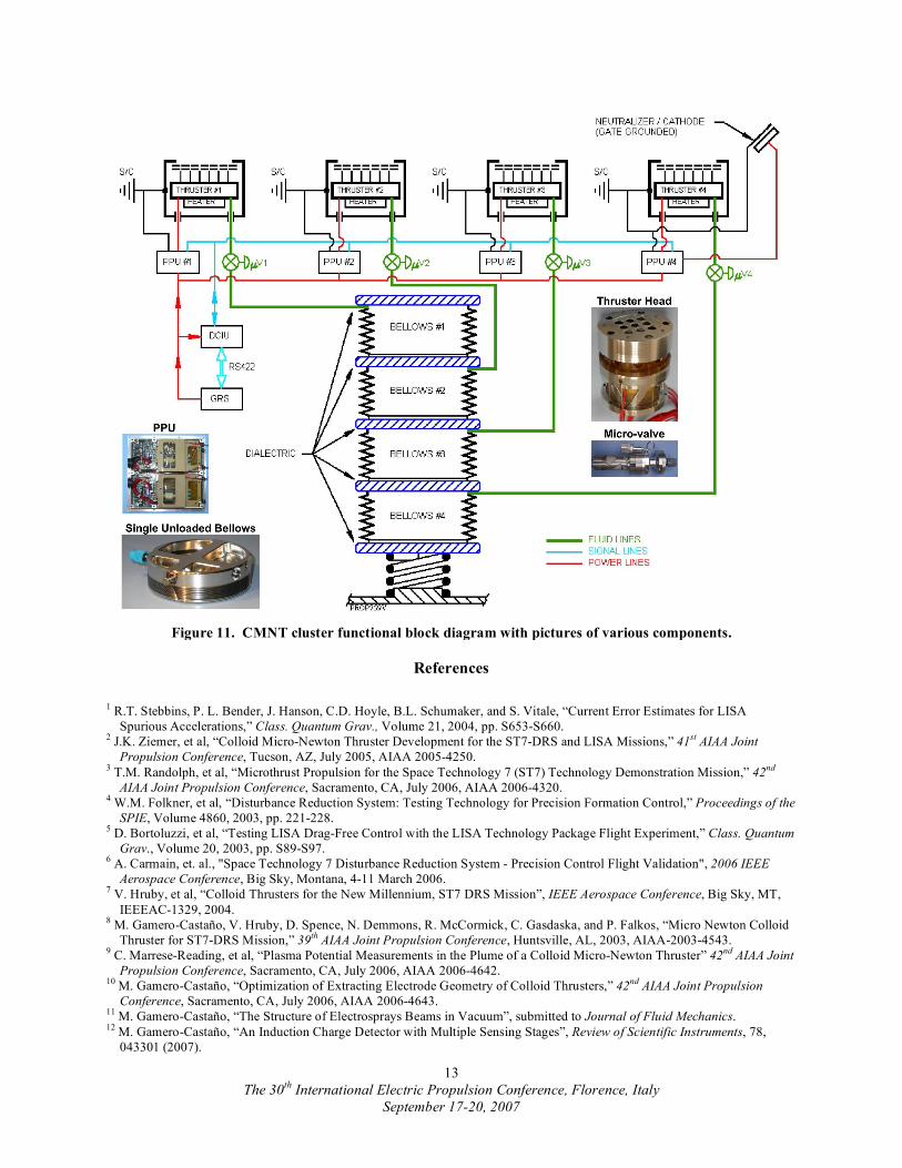
<0.1 µN/"Hz thrust noise. Figure 2 shows one flight
thruster cluster with four thruster subsystems, and
Figure 11 (located at the end of the paper) shows a
functional block diagram for the CMNT cluster. We
will now discuss the subsystems of the Busek CMNT
being developed for the ST7-DRS Mission.
A. Overview of CMNT Subsystems
1. Thruster Head
The thruster head comprises a manifold that feeds
nine emitters in parallel, a heater to control temperature
and propellant physical properties (i.e. viscosity,
conductivity, etc.), and electrodes that extract and
accelerate the propellant. The flight design thruster
head has been used in single-thruster system test boxes
for long-duration testing and performance validation
measurements described later in this paper. Some
materials used in the manifold have been changed to
ensure compatibility with the propellant.
2. Propellant Feed System
Propellant is stored in four electrically isolated stainless steel bellows compressed by four constant force springs
set to supply four microvalves with propellant at approximately 1 atm of pressure. The microvalve is piezo-actuated
using ~1 mW of power to control the propellant flow rate and current to better than 1 nA without significant
physical motion. This level of precision corresponds to #0.01 µN of thrust, with a response time over its full range
of less than 0.5 s. The flight microvalve design has been part of multiple single- and multiple-emitter long-duration
tests, accumulating over 15,000 hours of total test time without incident in the design temperature range. Again here
materials have been changed to ensure propellant compatibility and microvalve function at high temperature.
3. Cathode Neutralizer
The cathode neutralizer developed by Busek is made from a carbon nanotube (CNT) base with an extractor
electrode. The cathode is capable of producing 10 µA to 1 mA using extraction voltages of 250-800 V. One CNT
cathode has been tested alone in an ultra-high vacuum chamber for over 13,000 hours at 100 µA without incident.
CNT cathodes have also been tested successfully with operating thruster heads during multiple long-duration tests.
4. Thruster Electronics
The flight thruster electronics including 4 power processing units (PPUs) and one digital control and interface
unit (DCIU) for each cluster have completed qualification testing at the component level. EM and flight electronics
have over 8,000 hours of operation under vacuum controlling complete thruster sub-systems. The PPU includes the
high-voltage DC-DC converters that have been specifically designed and tested for this application by Busek Co.
The DCIU controls all four thrusters and provides the command and telemetry interface to the spacecraft and DRS.
§ The maximum obtainable thrust within the set current and voltage range is expected to be 40 µN, and even higher levels (as
high as 100 µN) can be achieved by directly controlling the microvalve to reach current levels up to 10 µA. However, higher
current levels lead to more overspray onto the extractor electrode, shortening the available lifetime of the CMNT. The maximum
current level of 5.4 µA is designed to prevent any overspray while providing >30% margin on the maximum thrust requirement.
Figure 2. Busek Colloid Micro-Newton Thruster
(CMNT) Flight Cluster 1 including four thruster
heads, electronics, and cathode neutralizer (visible) in
thermal-vacuum environmental test setup.
The 30th
International Electric Propulsion Conference, Florence, Italy
September 17-20, 2007
5
IV Microthruster Validation Tests and Flight Production
Test validation of the Busek CMNT design for ST7 presents several challenges for a traditional qualification
program. The primary challenge is making direct performance measurements with the flight clusters due to the
difficulties of sub micronewton resolution thrust stand measurements with such a large mass. Also, since thruster
lifetime is expected to be independent of the number of operating thrusters (each thruster head has enough emitters
to provide the full thrust range and operates independently in the cluster), assembling and testing an entire cluster to
assess lifetime would be expensive, time intensive, and not necessary. To avoid this problem, a validation plan was
formulated to perform certain validation tests at the “box” level, with a single electronics, bellows, microvalve, and
thruster combination. Other protoflight tests are performed at the flight cluster level (see Table 5). In this plan,
thrust stand measurements necessary for verifying thrust range, precision, noise, response time, and specific impulse
requirements are made at the box level, where the small box mass enables reasonably accurate thrust measurements.
Using these box level thrust measurements, correlations can be made to validate the determination of thrust from
current and voltage measurements. Current and voltage measurements are then made at the cluster level, using the
model validated by thrust stand measurements, to estimate thrust at the cluster level. Because lifetime and plume
measurements are almost entirely independent of the cluster thermal and structural design, these requirements are
also verified at the box level for test simplicity. Because the structural and thermal design of the box is very
dissimilar to the cluster design, these requirements are validated at the cluster level by protoflight testing.
Table 5. ST7 CMNT simplified validation matrix including status of each test.
Requirement Box Level Cluster Level Status
Thrust Range ! Partial
Thrust Precision ! Partial
Thrust Noise ! Partial
Thrust Response Time ! Partial
Specific Impulse ! Partial
Calculations show the flight thrusters meeting
requirements, preliminary thrust stand data
show that the calculations are within 2% of
measurements, and final measurements as a
function of temperature are ongoing
Operational Lifetime ! Formal Life Test 2B complete with 3478 hours
Plume Half-Angle !
Measurements complete; plume half-angle and
stability meet or exceed requirements
Environmental Dynamics
!
Both flight clusters passed full protoflight-level
vibration and shock testing; reassembled
clusters will be retested at workmanship levels
Environmental Temperature
!* !
Thermal-vacuum testing was performed on both
clusters and revealed material/propellant
compatibility issues that require reassembling
the clusters with new materials and retesting
*Originally only validated at the cluster level, box level thermal testing will be run in parallel with the flight unit reassembly to
test thruster system components. Environmental thermal validation testing will still be conducted at the cluster level as well.
A. Formal Life Test 2B
The operational time requirement for the ST7 mission is 60 days (1440 hours) total, including the colloid
microthrusters. The thrusters have been designed for a 90-day (2160 hour) mission, including consumables and
lifetime of all subsystems. To provide for pre-flight ground environmental qualification testing and increase the
chance for mission success, 50% margin has been applied to the 90-day lifetime design target, giving a goal for
lifetime demonstration of 3240 hours. During the mission, we expect the sun-opposing thrusters to operate at higher
thrust levels than the sun-facing thrusters, and these conditions are expected to be more strenuous on the thrusters.
With an expected thrust level for the sun-opposing thrusters of 18.0 ± 4.5 µN, we expect to require <140 µNs of
total impulse, consuming <58 g of propellant over the entire mission.
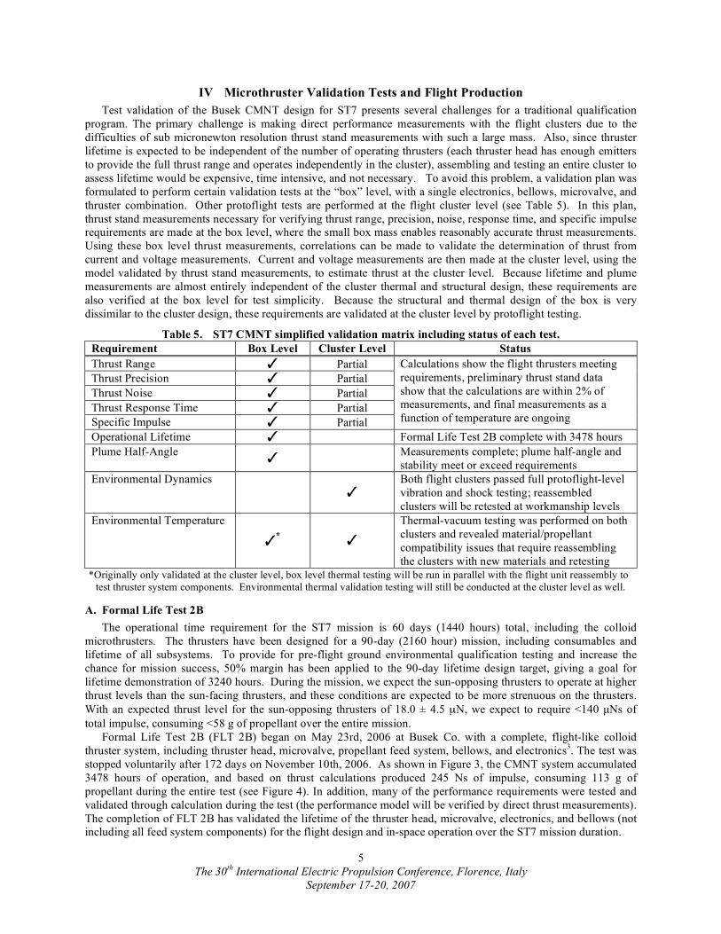
Formal Life Test 2B (FLT 2B) began on May 23rd, 2006 at Busek Co. with a complete, flight-like colloid
thruster system, including thruster head, microvalve, propellant feed system, bellows, and electronics3. The test was
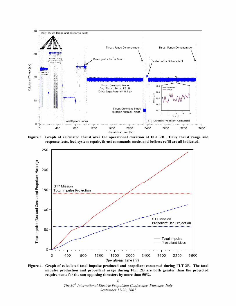
stopped voluntarily after 172 days on November 10th, 2006. As shown in Figure 3, the CMNT system accumulated
3478 hours of operation, and based on thrust calculations produced 245 Ns of impulse, consuming 113 g of
propellant during the entire test (see Figure 4). In addition, many of the performance requirements were tested and
validated through calculation during the test (the performance model will be verified by direct thrust measurements).
The completion of FLT 2B has validated the lifetime of the thruster head, microvalve, electronics, and bellows (not
including all feed system components) for the flight design and in-space operation over the ST7 mission duration.
The 30th
International Electric Propulsion Conference, Florence, Italy
September 17-20, 2007
6
Figure 3. Graph of calculated thrust over the operational duration of FLT 2B. Daily thrust range and
response tests, feed system repair, thrust commands mode, and bellows refill are all indicated.
Figure 4. Graph of calculated total impulse produced and propellant consumed during FLT 2B. The total
impulse production and propellant usage during FLT 2B are both greater than the projected
requirements for the sun-opposing thrusters by more than 50%.
ST7 Mission
ST7 Mission
The 30th
International Electric Propulsion Conference, Florence, Italy
September 17-20, 2007
7
1. Detailed chronology of events during FLT 2B
The first 500 hours of FLT 2B were focused on removing bubbles from the feed system by running near
maximum flow rate (see Ref. 3 for a description of bubble removal). Daily thrust range and response tests allowed
the progress of removing bubbles to be observed while operational hours accumulated. Due to bubbles passing out
of the emitters, the calculated thrust noise exceeded the 0.1 µN/!Hz requirement, but for only the first 232 hours.
Bubbles were completely removed from the system by 600 hours of operation, and we expect the flight thrusters to
reach bubble-free operation in much shorter periods (10’s of hours) due to process improvements. Also, an on-orbit
commissioning phase accommodates operation of the thrusters for 100’s of hours to pass bubbles before full system
operation is required. A slight leak in the propellant feed system near hour 500 of FLT 2B and the subsequent repair
(addition of epoxy on exterior of leaking feed system component—no other hardware was removed, touched, or
cleaned) provided enough excess propellant to form a ~1 G" path between the beam and extractor electrodes. This
level of impedance is not considered a failure (the power processing units are designed to operate effectively with a
load as low as 100 M"), and the thruster was set to operate in a low voltage (low thrust) mode until the impedance
increased. Fortunately, while the propellant used for the ST7 colloid microthruster has about the same conductivity
as seawater, it breaks down slowly into a dielectric at a reasonable voltage and current density. Clearing impedance
paths >1 G" caused by excess propellant simply becomes a matter of time at voltage using a controlled process with
frequent impedance measurements to indicate progress. Near hour 800, the voltage was once again increased to
nominal levels to speed up the clearing process, and the parallel high-impedance path was completely cleared near
hour 1000. During the final clearing process, thrust noise once again increased beyond the allowable requirement
for approximately 50 hours; however, thrust noise returned to acceptable values for the remainder of the test.
Just after 1000 hours, the thruster was set into mission simulation mode with a series of repeating thrust
commands provided by the DRS control algorithm team from NASA Goddard. The series of commands, lasting
approximately 20 minutes at 10 Hz, allowed the thruster to demonstrate flight-like conditions including fast (100
ms) response to both beam voltage and current (controlled by the microvalve) commands, determined by the on-
board software in the thruster DCIU. As shown in the small inset graph of Figure 3, the simulated commands
centered around 19 µN, and varied by as much as +/- 1 µN. The thruster ran successfully in this mode for over 1000
hours of continuous, unattended operation. After 2300 hours of total operation (surpassing the 90-day mission and
consumables requirement), the thruster showed signs of running out of propellant, and the average thrust command
level was reduced to 6 µN to extend the test. At 2366 hours, the thruster finally ran out of propellant, the test facility
was opened to refill the bellows, and no other components were touched, removed, or cleaned. The test started
again with new software for simulating the ST7 avionics unit, running again with the “mission simulation” thrust
commands repeating successfully for an additional 1000 hours. Using new startup procedures, the thruster operated
without any signs of bubbles after only 48 hours beyond the restart after refilling the bellows. The test was stopped
voluntarily after 3478 hours of total operation with a successful demonstration of thrust range and performance. The
completion of FLT 2B validated the thruster head, microvalve, electronics, and bellows lifetime at the system-level,
but leaks in the feed-system required new component designs that were validated in parallel, accelerated lifetests.
2. End of Life Functional Test Results
At the end of FLT 2B, after approximately 3472 hours of operation, a functional test was performed to
demonstrate the performance of the thruster. As shown in Figure 5, the functional test consisted of demonstrating
full thrust range operation in both constant current and constant voltage, low- and high-thrust modes. During each
step the response time and accuracy was measured based on thrust calculations from beam voltage and current and
found to be within acceptable limits in each case. The time to reach full thrust (30 µN within <0.1 µN) from the
minimum current and voltage levels was found to be approximately 10 s in thrust command mode, with the voltage
ramp rate set to 400V/s (adjustable up to 10000 V/s). Response times can be longer if bubbles are present in the
feed system; however, by this time in the life test, the thruster was running without any signs of bubbles. Thrust
noise was also calculated based on current and voltage measurements during a 1-hour long run at fixed operating
conditions. Figure 6 shows graphs of thrust and thrust noise from this period, clearly meeting the ST7 requirement.
B. Plume Divergence and Stability Measurements
Models and measurements of breadboard and EM-level CMNT exhaust plumes at JPL have shown that no
charged particles exit the thruster beyond a 35-degree half-angle at the most divergent operating condition. Mass
deposition measurements using a temperature controlled quartz-crystal microbalance have shown that no measurable
deposition occurs outside of a 45 degree half-angle. Emissive probe measurements show beam potentials 0-30 V
with a constant divergence angle at >10 cm downstream of the thruster head, even without using a neutralizer9. To
date, all JPL tests show that the Busek CMNT will meet ST7 and future LISA contamination requirements.

The 30th
International Electric Propulsion Conference, Florence, Italy
September 17-20, 2007
8
Figure 5. Functional test performed at the end of FLT2B, beginning after 3472 hours of operation.
Minimum and maximum thrust was demonstrated as well as slew rates.
Figure 6. Calculated thrust and thrust noise from a one-hour run at constant thrust as part of the final
functional test of FLT 2B (run began ~100 minutes after the beginning of the functional test).
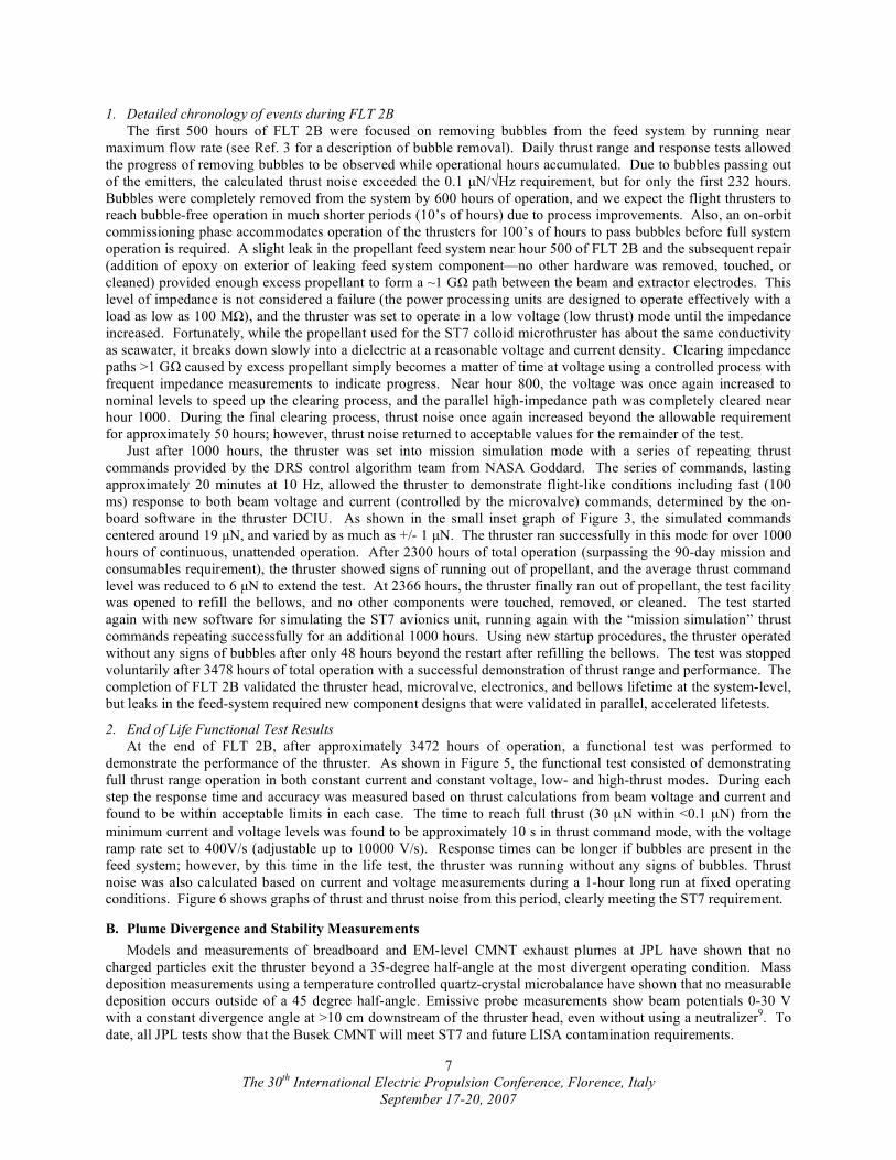
Busek measurements of exhaust beam divergence and stability using a beam target with 56 electrometers (each
with ~nA resolution) in a cross pattern are shown in Figure 7. Even for the worst-case conditions of the lowest
beam voltage (lowest thrust levels), the exhaust beam half-angle encompassing 95% of the current is <25 deg.
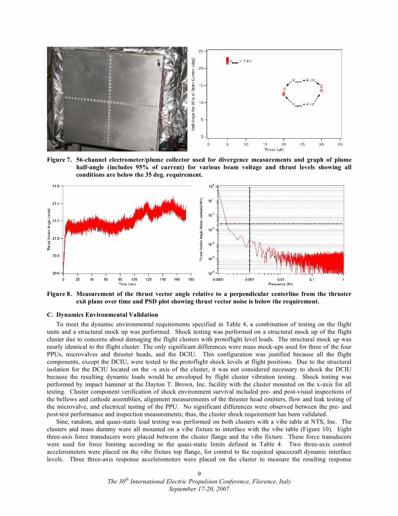
(requirement is <35 deg.). Measurements of the exhaust beam centerline location on the beam target over time are
shown in Figure 8. While it seems an offset of ~21 mrad (1.2 deg.) is present from misalignment of the beam target
with the thruster exhaust, the location of the beam centerline is stable and meets requirements (<2.5 mrad/"Hz) over
the measurement bandwidth of 1 mHz to 5 Hz. Higher noise levels at lower frequency are due to electrometer drift
in the beam collector sensors. These direct measurements of exhaust beam divergence and stability confirm the
previous plume measurements taken at Busek and JPL.
The 30th
International Electric Propulsion Conference, Florence, Italy
September 17-20, 2007
9
Figure 7. 56-channel electrometer/plume collector used for divergence measurements and graph of plume
half-angle (includes 95% of current) for various beam voltage and thrust levels showing all
conditions are below the 35 deg. requirement.
Figure 8. Measurement of the thrust vector angle relative to a perpendicular centerline from the thruster
exit plane over time and PSD plot showing thrust vector noise is below the requirement.
C. Dynamics Environmental Validation
To meet the dynamic environmental requirements specified in Table 4, a combination of testing on the flight
units and a structural mock up was performed. Shock testing was performed on a structural mock up of the flight
cluster due to concerns about damaging the flight clusters with protoflight level loads. The structural mock up was
nearly identical to the flight cluster. The only significant differences were mass mock-ups used for three of the four
PPUs, microvalves and thruster heads, and the DCIU. This configuration was justified because all the flight
components, except the DCIU, were tested to the protoflight shock levels at flight positions. Due to the structural
isolation for the DCIU located on the -x axis of the cluster, it was not considered necessary to shock the DCIU
because the resulting dynamic loads would be enveloped by flight cluster vibration testing. Shock testing was
performed by impact hammer at the Dayton T. Brown, Inc. facility with the cluster mounted on the x-axis for all
testing. Cluster component verification of shock environment survival included pre- and post-visual inspections of
the bellows and cathode assemblies, alignment measurements of the thruster head emitters, flow and leak testing of
the microvalve, and electrical testing of the PPU. No significant differences were observed between the pre- and
post-test performance and inspection measurements; thus, the cluster shock requirement has been validated.
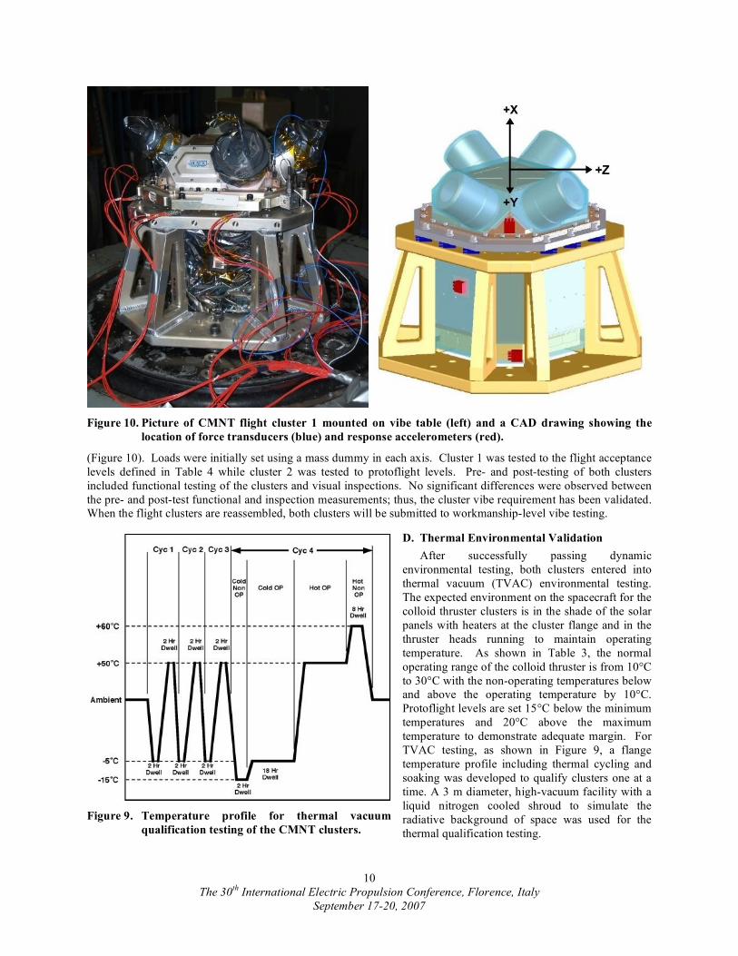
Sine, random, and quasi-static load testing was performed on both clusters with a vibe table at NTS, Inc. The
clusters and mass dummy were all mounted on a vibe fixture to interface with the vibe table (Figure 10). Eight
three-axis force transducers were placed between the cluster flange and the vibe fixture. These force transducers
were used for force limiting according to the quasi-static limits defined in Table 4. Two three-axis control
accelerometers were placed on the vibe fixture top flange, for control to the required spacecraft dynamic interface
levels. Three three-axis response accelerometers were placed on the cluster to measure the resulting response
The 30th
International Electric Propulsion Conference, Florence, Italy
September 17-20, 2007
10
(Figure 10). Loads were initially set using a mass dummy in each axis. Cluster 1 was tested to the flight acceptance
levels defined in Table 4 while cluster 2 was tested to protoflight levels. Pre- and post-testing of both clusters
included functional testing of the clusters and visual inspections. No significant differences were observed between
the pre- and post-test functional and inspection measurements; thus, the cluster vibe requirement has been validated.
When the flight clusters are reassembled, both clusters will be submitted to workmanship-level vibe testing.
D. Thermal Environmental Validation
After successfully passing dynamic
environmental testing, both clusters entered into
thermal vacuum (TVAC) environmental testing.
The expected environment on the spacecraft for the
colloid thruster clusters is in the shade of the solar
panels with heaters at the cluster flange and in the
thruster heads running to maintain operating
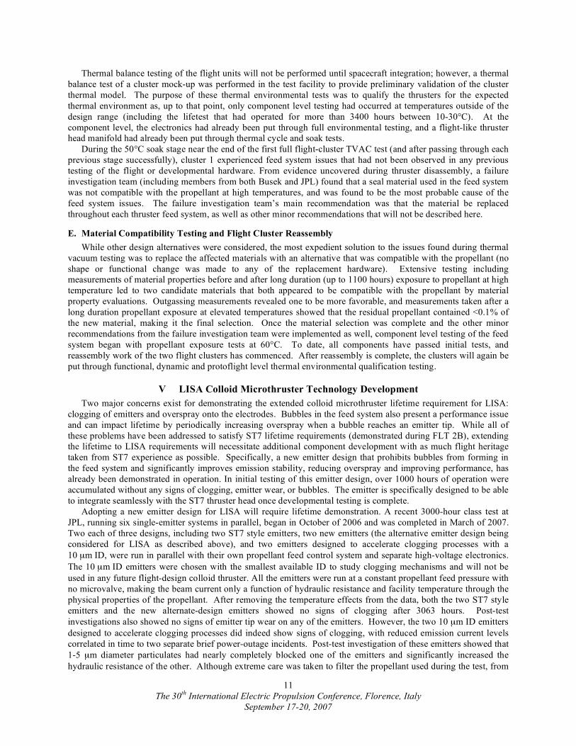
temperature. As shown in Table 3, the normal
operating range of the colloid thruster is from 10°C
to 30°C with the non-operating temperatures below
and above the operating temperature by 10°C.
Protoflight levels are set 15°C below the minimum
temperatures and 20°C above the maximum
temperature to demonstrate adequate margin. For
TVAC testing, as shown in Figure 9, a flange
temperature profile including thermal cycling and
soaking was developed to qualify clusters one at a
time. A 3 m diameter, high-vacuum facility with a
liquid nitrogen cooled shroud to simulate the
radiative background of space was used for the
thermal qualification testing.
Figure 9. Temperature profile for thermal vacuum
qualification testing of the CMNT clusters.
Figure 10. Picture of CMNT flight cluster 1 mounted on vibe table (left) and a CAD drawing showing the
location of force transducers (blue) and response accelerometers (red).
The 30th
International Electric Propulsion Conference, Florence, Italy
September 17-20, 2007
11
Thermal balance testing of the flight units will not be performed until spacecraft integration; however, a thermal
balance test of a cluster mock-up was performed in the test facility to provide preliminary validation of the cluster
thermal model. The purpose of these thermal environmental tests was to qualify the thrusters for the expected
thermal environment as, up to that point, only component level testing had occurred at temperatures outside of the
design range (including the lifetest that had operated for more than 3400 hours between 10-30°C). At the
component level, the electronics had already been put through full environmental testing, and a flight-like thruster
head manifold had already been put through thermal cycle and soak tests.
During the 50°C soak stage near the end of the first full flight-cluster TVAC test (and after passing through each
previous stage successfully), cluster 1 experienced feed system issues that had not been observed in any previous
testing of the flight or developmental hardware. From evidence uncovered during thruster disassembly, a failure
investigation team (including members from both Busek and JPL) found that a seal material used in the feed system
was not compatible with the propellant at high temperatures, and was found to be the most probable cause of the
feed system issues. The failure investigation team’s main recommendation was that the material be replaced
throughout each thruster feed system, as well as other minor recommendations that will not be described here.
E. Material Compatibility Testing and Flight Cluster Reassembly
While other design alternatives were considered, the most expedient solution to the issues found during thermal
vacuum testing was to replace the affected materials with an alternative that was compatible with the propellant (no
shape or functional change was made to any of the replacement hardware). Extensive testing including
measurements of material properties before and after long duration (up to 1100 hours) exposure to propellant at high
temperature led to two candidate materials that both appeared to be compatible with the propellant by material
property evaluations. Outgassing measurements revealed one to be more favorable, and measurements taken after a
long duration propellant exposure at elevated temperatures showed that the residual propellant contained <0.1% of
the new material, making it the final selection. Once the material selection was complete and the other minor
recommendations from the failure investigation team were implemented as well, component level testing of the feed
system began with propellant exposure tests at 60°C. To date, all components have passed initial tests, and
reassembly work of the two flight clusters has commenced. After reassembly is complete, the clusters will again be
put through functional, dynamic and protoflight level thermal environmental qualification testing.
V LISA Colloid Microthruster Technology Development
Two major concerns exist for demonstrating the extended colloid microthruster lifetime requirement for LISA:
clogging of emitters and overspray onto the electrodes. Bubbles in the feed system also present a performance issue
and can impact lifetime by periodically increasing overspray when a bubble reaches an emitter tip. While all of
these problems have been addressed to satisfy ST7 lifetime requirements (demonstrated during FLT 2B), extending
the lifetime to LISA requirements will necessitate additional component development with as much flight heritage
taken from ST7 experience as possible. Specifically, a new emitter design that prohibits bubbles from forming in
the feed system and significantly improves emission stability, reducing overspray and improving performance, has
already been demonstrated in operation. In initial testing of this emitter design, over 1000 hours of operation were
accumulated without any signs of clogging, emitter wear, or bubbles. The emitter is specifically designed to be able
to integrate seamlessly with the ST7 thruster head once developmental testing is complete.
Adopting a new emitter design for LISA will require lifetime demonstration. A recent 3000-hour class test at
JPL, running six single-emitter systems in parallel, began in October of 2006 and was completed in March of 2007.
Two each of three designs, including two ST7 style emitters, two new emitters (the alternative emitter design being
considered for LISA as described above), and two emitters designed to accelerate clogging processes with a
10 µm ID, were run in parallel with their own propellant feed control system and separate high-voltage electronics.
The 10 µm ID emitters were chosen with the smallest available ID to study clogging mechanisms and will not be
used in any future flight-design colloid thruster. All the emitters were run at a constant propellant feed pressure with
no microvalve, making the beam current only a function of hydraulic resistance and facility temperature through the
physical properties of the propellant. After removing the temperature effects from the data, both the two ST7 style
emitters and the new alternate-design emitters showed no signs of clogging after 3063 hours. Post-test
investigations also showed no signs of emitter tip wear on any of the emitters. However, the two 10 µm ID emitters
designed to accelerate clogging processes did indeed show signs of clogging, with reduced emission current levels
correlated in time to two separate brief power-outage incidents. Post-test investigation of these emitters showed that
1-5 µm diameter particulates had nearly completely blocked one of the emitters and significantly increased the
hydraulic resistance of the other. Although extreme care was taken to filter the propellant used during the test, from

The 30th
International Electric Propulsion Conference, Florence, Italy
September 17-20, 2007
12
optical and SEM investigation the particulates where found to be made of the emitter material, likely created during
the fabrication process. New fabrication processes are currently being developed and tested to reduce the risk of
forming loose particulates, including significant flushing and back flushing at high pressure. Lessons learned will be
applied to a new multiple-emitter thruster head design that will be tested for at least 8000 hours by the end of 2009.
In addition to developing and testing new emitters, models of ion/droplet trajectories have been developed and
verified to reduce and possibly even eliminate significant overspray onto the electrodes10,11
. Detailed angular
measurements of current density, particle energy, and charge-to-mass ratio12
were made using a single emitter over
its full operating range to validate the model. This model has allowed better electrode designs that will not have as
much overspray, even at the highest current levels. Models of bubble formation and the impact of bubbles on
performance have also been developed and verified by experiments. These models have provided guidance to feed
system design, material selection, and most importantly the propellant contamination levels required to prevent
bubble formation. While the ST7 design operates bubble-free after 10 to 100’s hours of operation, new designs
should eliminate them completely. Both the new emitter and electrode designs as well as the changes to the feed
system will be thoroughly tested before being integrated into the prototype LISA microthruster design.
Key risks for the LISA microthruster technology development of both colloid and FEEP thrusters revolve around
the issue of lifetime and the unlikelihood of direct verification by ground testing alone. Simply put, the resources
required for such a demonstration of a statistically valid set of tests are not available or possible within the available
amount of development time. Instead, for the colloid thrusters, physics-based models of failure and wear
mechanisms are under development and will be validated in long duration tests of flight-like hardware. This same
approach has been used previously for xenon ion thrusters, first demonstrated on Deep Space 1 (formerly Space
Technology 1, ST1) for 8000 hours, then qualified and used for missions that required >30,000 hours of operation
including the DAWN mission set to launch in the Fall of 2007. Already, more than 20,000 hours of total
accumulated test time between multiple colloid thruster designs have allowed us to focus on the most important
lifetime issues of emitter wear and clogging, overspray onto extractor and accelerator electrodes, and providing
consistent flow to the emitters. While these areas have all been addressed for ST7 lifetime requirements, for the
LISA mission lifetime, further technology developments are required. By using as much flight heritage from ST7 as
possible, new component and system-level long duration tests along with colloid thruster lifetime models will
provide the basis for LISA microthruster lifetime qualification.
VI Conclusion
With developmental and much of the qualification testing complete, the ST7 Colloid Micro-Newton Thruster
validation testing and flight production is nearing completion. Formal Life Test 2B was completed demonstrating
more than 3400 hours of operation of a complete single-thruster system before being stopped voluntarily.
Performance measurements based on thrust models using measured beam voltage and current show the CMNT
technology meets or exceeds the precision formation flying and drag-free propulsion range, resolution, and noise
requirements of ST7 and LISA. Beam profile measurements show the exhaust beam has a predictable thrust vector
and a stable position over the measurement bandwidth of interest, and that the beam divergence is well within
requirements over all operating conditions. Busek Co., Inc. completed flight production of two clusters with four
thrusters each and qualification testing began in early 2007. Both clusters passed through initial functional testing
and environmental dynamics testing without any issues. During thermal vacuum testing, at high temperature a
material and propellant incompatibility issue caused qualification testing to stop while the cause was determined and
corrected. Material compatibility testing has been completed, and a suitable replacement material has been found.
Flight cluster reassembly and testing is ongoing at Busek with qualification testing resuming in the Fall of 2007.
Acknowledgments
The research work described in this paper was carried out at the Jet Propulsion Laboratory, California Institute of
Technology, under a contract with the National Aeronautics and Space Administration.
Reference herein to any specific commercial product, process, or service by trade name, trademark,
manufacturer, or otherwise, does not constitute or imply its endorsement by the United States Government or the Jet
Propulsion Laboratory, California Institute of Technology.
The 30th
International Electric Propulsion Conference, Florence, Italy
September 17-20, 2007
13
References
1 R.T. Stebbins, P. L. Bender, J. Hanson, C.D. Hoyle, B.L. Schumaker, and S. Vitale, “Current Error Estimates for LISA
Spurious Accelerations,” Class. Quantum Grav., Volume 21, 2004, pp. S653-S660. 2 J.K. Ziemer, et al, “Colloid Micro-Newton Thruster Development for the ST7-DRS and LISA Missions,” 41
st AIAA Joint
Propulsion Conference, Tucson, AZ, July 2005, AIAA 2005-4250. 3 T.M. Randolph, et al, “Microthrust Propulsion for the Space Technology 7 (ST7) Technology Demonstration Mission,” 42
nd
AIAA Joint Propulsion Conference, Sacramento, CA, July 2006, AIAA 2006-4320. 4 W.M. Folkner, et al, “Disturbance Reduction System: Testing Technology for Precision Formation Control,” Proceedings of the
SPIE, Volume 4860, 2003, pp. 221-228. 5 D. Bortoluzzi, et al, “Testing LISA Drag-Free Control with the LISA Technology Package Flight Experiment,” Class. Quantum
Grav., Volume 20, 2003, pp. S89-S97. 6 A. Carmain, et. al., "Space Technology 7 Disturbance Reduction System - Precision Control Flight Validation", 2006 IEEE
Aerospace Conference, Big Sky, Montana, 4-11 March 2006. 7 V. Hruby, et al, “Colloid Thrusters for the New Millennium, ST7 DRS Mission”, IEEE Aerospace Conference, Big Sky, MT,
IEEEAC-1329, 2004. 8 M. Gamero-Castaño, V. Hruby, D. Spence, N. Demmons, R. McCormick, C. Gasdaska, and P. Falkos, “Micro Newton Colloid
Thruster for ST7-DRS Mission,” 39th
AIAA Joint Propulsion Conference, Huntsville, AL, 2003, AIAA-2003-4543. 9 C. Marrese-Reading, et al, “Plasma Potential Measurements in the Plume of a Colloid Micro-Newton Thruster” 42
nd AIAA Joint
Propulsion Conference, Sacramento, CA, July 2006, AIAA 2006-4642. 10
M. Gamero-Castaño, “Optimization of Extracting Electrode Geometry of Colloid Thrusters,” 42nd
AIAA Joint Propulsion
Conference, Sacramento, CA, July 2006, AIAA 2006-4643. 11
M. Gamero-Castaño, “The Structure of Electrosprays Beams in Vacuum”, submitted to Journal of Fluid Mechanics. 12
M. Gamero-Castaño, “An Induction Charge Detector with Multiple Sensing Stages”, Review of Scientific Instruments, 78,
043301 (2007).
Figure 11. CMNT cluster functional block diagram with pictures of various components.