Flexural Fatigue Response of Repaired S2 … Fatigue Response of Repaired ... vacuum-bag technology...
26
Flexural Fatigue Response of Repaired S2-Glass/Vinyl Ester Composites by Uday K. Vaidya, Biju Mathew, and James M. Sands ARL-TR-4912 August 2009 Approved for public release; distribution is unlimited.
Transcript of Flexural Fatigue Response of Repaired S2 … Fatigue Response of Repaired ... vacuum-bag technology...

Flexural Fatigue Response of Repaired
S2-Glass/Vinyl Ester Composites
by Uday K. Vaidya, Biju Mathew, and James M. Sands
ARL-TR-4912 August 2009
Approved for public release; distribution is unlimited.

NOTICES
Disclaimers The findings in this report are not to be construed as an official Department of the Army position unless so designated by other authorized documents. Citation of manufacturer’s or trade names does not constitute an official endorsement or approval of the use thereof. Destroy this report when it is no longer needed. Do not return it to the originator.

Army Research Laboratory Aberdeen Proving Ground, MD 21005-5069
ARL-TR-4912 August 2009
Flexural Fatigue Response of Repaired S2-Glass/Vinyl Ester Composites
Uday K. Vaidya
The University of Alabama at Birmingham
Biju Mathew North Dakota State University
James M. Sands
Weapons and Materials Research Directorate, ARL Approved for public release; distribution is unlimited.

ii
REPORT DOCUMENTATION PAGE Form Approved OMB No. 0704-0188
Public reporting burden for this collection of information is estimated to average 1 hour per response, including the time for reviewing instructions, searching existing data sources, gathering and maintaining the data needed, and completing and reviewing the collection information. Send comments regarding this burden estimate or any other aspect of this collection of information, including suggestions for reducing the burden, to Department of Defense, Washington Headquarters Services, Directorate for Information Operations and Reports (0704-0188), 1215 Jefferson Davis Highway, Suite 1204, Arlington, VA 22202-4302. Respondents should be aware that notwithstanding any other provision of law, no person shall be subject to any penalty for failing to comply with a collection of information if it does not display a currently valid OMB control number. PLEASE DO NOT RETURN YOUR FORM TO THE ABOVE ADDRESS.
1. REPORT DATE (DD-MM-YYYY)
August 2009 2. REPORT TYPE
Final 3. DATES COVERED (From - To)
December 2005–January 2007 4. TITLE AND SUBTITLE
Flexural Fatigue Response of Repaired S2-Glass/Vinyl Ester Composites 5a. CONTRACT NUMBER
W911NF-04-2-0018 5b. GRANT NUMBER
5c. PROGRAM ELEMENT NUMBER
6. AUTHOR(S)
Uday K. Vaidya,* Biju Mathew,† and James M. Sands 5d. PROJECT NUMBER
H84 5e. TASK NUMBER
5f. WORK UNIT NUMBER
7. PERFORMING ORGANIZATION NAME(S) AND ADDRESS(ES)
Army Research Laboratory ATTN: RDRL-WMM-D Aberdeen Proving Ground, MD 21005-5069
8. PERFORMING ORGANIZATION REPORT NUMBER
ARL-TR-4912
9. SPONSORING/MONITORING AGENCY NAME(S) AND ADDRESS(ES)
10. SPONSOR/MONITOR’S ACRONYM(S)
11. SPONSOR/MONITOR'S REPORT NUMBER(S)
12. DISTRIBUTION/AVAILABILITY STATEMENT
Approved for public release; distribution is unlimited.
13. SUPPLEMENTARY NOTES *The University of Alabama at Birmingham, Department of Materials Science and Engineering, Birmingham, AL 35216
†Composites Research Laboratory, Department of Mechanical Engineering & Applied Mechanics, North Dakota State University, Fargo, ND 58105
14. ABSTRACT
Vacuum-assisted resin transfer molding is a promising, affordable technique for producing composite integral armor (CIA) and thick-section composites for U.S. Army-relevant applications. Among several constituents, the CIA uses S2-glass/epoxy and/or S2-glass/vinyl ester composites in its construction. The S2-glass-reinforced composite provides ballistic protection and load bearing due to the flexural loading caused from vehicle movement over various terrains. The S2-glass-reinforced composite is subjected to different levels of delamination when impacted by projectiles. The present study focuses on the repair of S2-glass/epoxy composites subjected to a clean perforation type of ballistic impact scenario and post-repair flexural response of the composite panels. Simple repair solutions involving the use of different plugs reinforcing the damage (12.7-, 25.4-, and 38.1-mm [0.5-, 1-, and 1.5-in] clean perforations) have been implemented in S2-glass/vinyl ester laminates. Static and fatigue tests were conducted under flexural loading. The effects of implementing the repair strategies on the flexure performance have been reported.
15. SUBJECT TERMS
Curie particles, zinc complex, solution synthesis, composite, repair
16. SECURITY CLASSIFICATION OF: 17. LIMITATION OF ABSTRACT
UU
18. NUMBER OF PAGES
26
19a. NAME OF RESPONSIBLE PERSON
James M. Sands a. REPORT
Unclassified b. ABSTRACT
Unclassified c. THIS PAGE
Unclassified 19b. TELEPHONE NUMBER (Include area code)
410-306-0878 Standard Form 298 (Rev. 8/98)
Prescribed by ANSI Std. Z39.18

iii
Contents
List of Figures iv
List of Tables v
Acknowledgments vi
1. Introduction 1
2. Vacuum-Assisted Resin Transfer Molding 2
3. Repair Strategies 2
4. Processing and Repairing Laminates 4
5. Experimental 4
5.1 Set 1 Experiments ............................................................................................................5
5.1.1 Microstructural Studies .........................................................................................6
5.1.2 Summary of Preliminary Tests ..............................................................................7
5.2 Set 2 Experiments ............................................................................................................8
5.2.1 Thickness ...............................................................................................................8
5.2.2 Hole Diameter .......................................................................................................8
5.3 Fatigue Tests....................................................................................................................9
5.3.1 Effect of Hole ......................................................................................................10
5.3.2 Effect of Carbon/Epoxy Ply Doubler ..................................................................10
5.3.3 Effect of Microballoon/Epoxy .............................................................................12
5.3.4 Microballoon/Epoxy-Plugged Hole With Carbon/Epoxy Ply Doubler ...............13
6. Summary 14
7. References 15
Distribution List 16

iv
List of Figures
Figure 1. Typical ballistic impact damage of an S2-glass/vinyl ester laminate. .............................3
Figure 2. Repair schemes: (a) virgin laminate, (b) virgin laminate with carbon/epoxy ply doubler, (c) laminate with a clean hole, (d) laminate with a microballoon/epoxy-plugged hole or chopped strand mat (CSM)/epoxy-plugged hole, (e) laminate with doubler ply on each side of the clean hole, and (f) laminate with a microballoon/epoxy-plugged hole and doubler ply on each side of the clean hole. ................................................................................3
Figure 3. Load-deflection curves from three-point bend tests on 3.81-mm-thick S2-glass/vinyl ester composites (“with” and “without” repair). .....................................................5
Figure 4. Load-strain (strain gage measured) curves from three-point bend tests on 3.81-mm-thick S2-glass/vinyl ester composites (“with” and “without” repair). .......................6
Figure 5. Microstructure of S2-glass/vinyl ester samples after three-point bend tests. The left-hand column is the edge of the sample before sectioning, and the right-hand column is the sectioned view. Views: (a and b) CSM/epoxy plug, (c and d) virgin/undamaged, (e and f) clean hole, and (g and h) microballoon/epoxy plug. ...................................................7
Figure 6. Effect of thickness: four-point bend flexure of S2-glass/vinyl ester laminates. .............8
Figure 7. Effect of hole diameter: four-point bend flexure of S2-glass/vinyl ester laminates. ......9
Figure 8. Effect of hole: deflection vs. number of cycles. ...........................................................11
Figure 9. Fatigue tests—effect of carbon/epoxy doubler (unfilled hole): (1) virgin, (2) virgin with doubler ply, (3) 12.7-mm hole with doubler, (4) 25.4-mm hole with doubler, and (5) 38.1-mm hole with doubler. ..........................................................................11
Figure 10. Fatigue tests—microballoon/epoxy plugs: (1) virgin, (2) 12.7-mm hole, and (3) 25.4-mm hole. Data for 38.1-mm hole was not available. ................................................12
Figure 11. Fatigue tests—carbon/epoxy doubler + microballoon/epoxy plug: (1) virgin, (2) 12.7-mm hole, (3) 25.4-mm hole, and (4) 38.1-mm hole. .................................................13

v
List of Tables
Table 1. Summary of fatigue tests on samples with hole. ............................................................10
Table 2. Summary of fatigue tests: carbon/epoxy ply doubler. ...................................................12
Table 3. Summary of fatigue tests: microballoon/epoxy plug. ....................................................13
Table 4. Summary of fatigue tests: for carbon/epoxy doubler with microballoon/epoxy plug. ..14

vi
Acknowledgments
This research was conducted as a subcontract to North Dakota State University from Tuskegee University, AL, under the Tuskegee University Research Consortium. Research support provided by the U.S. Army Research Office under grant no. DAAH04-95-01-0369 to the consortium is acknowledged.

1
1. Introduction
Lighter-weight ground combat vehicles, marine bodies, and aircraft structures using advanced fabric/textile composites and/or layered material architecture are important because they offer improved deployability, survivability, and agility (1). In light of recently emerging, affordable techniques such as vacuum-assisted resin transfer molding (VARTM) (2), performance evaluations have assumed increasing importance due to the lack of historical databases on new materials development efforts. Components such as the front and rear upper and lower hull, crew capsule, rear-engine bulkhead, ramp, and sidewalls utilize composites with various types of fabric architectures and resin compositions (e.g., S2 glass, vinyl ester, epoxy, and phenolic resins) as monocoque or sandwich hybrid constructions (1–3). Delamination damage due to ballistic, high strain rate, and intermediate velocity impacts are critical in most composite structural parts (4, 5). Many composite structures used in U.S. Army applications are subjected to severe fatigue-loading conditions and harsh environments over long periods of time. Their fatigue life and performance depend on fatigue damage tolerance and the rates of property degradation under cyclic or pulse loads. Fatigue conditions are relevant to the following Army applications (6):
• composite armored vehicles
• weapon systems (e.g., electromagnetic gun components, crusader cannons, howitzer trails, motor base plates)
• composite assault bridges and future line-of-communication bridging
• rotorcraft systems (e.g., Comanche, Apache)
Composite repair reports are focused on lightweight, aerospace-type laminates and sandwich constructions, where the laminate and facesheet are thin structures (<3 mm) (7–10). Early efforts to repair advanced composites generally led to an external patch concept. Graphite/epoxy laminates have been subjected to a variety of repair techniques that include bonded-scarf joint flush repair, double-scarf joint flush repair, blind-side bonded-scarf repair, and blind-side sandwich repair (7–10). Joining thermoplastic composites has received some attention as well (11, 12). Little effort has gone into developing repair processes and materials for composites produced affordably, including VARTM and those that possess thick sections. There is a need to standardize repair strategies for affordably produced composites. This report presents preliminary work on VARTM-produced laminates subjected to idealized damage and repaired through different plugs. After implementing the repair, the performance of the laminates has been evaluated for static and flexural fatigue loading.

2
2. Vacuum-Assisted Resin Transfer Molding
VARTM is of interest in low-cost, innovative developments as it uses one-sided tooling and vacuum-bag technology (1). It is an emerging manufacturing technique that holds promise as an affordable alternative to traditional autoclave molding and automated fiber placement for producing large-scale structural parts. In VARTM, the fibrous preform is laid on a single-sided tool, which is bagged along with the infusion and vacuum lines. The resin is then infused through the preform, which causes simultaneous wetting in its in-plane and transverse directions. This process is proving to be a very attractive alternative to spray-up or impregnation methods, and it is far less expensive than conventional manufacturing methods, such as autoclave and/or compression molding. Large structural parts with high fiber-volume fractions can be produced rapidly. Other advantages of VARTM are low process volatile emissions, high fiber-to-resin ratios, and good process repeatability.
3. Repair Strategies
There are several ways in which a projectile impact on a composite laminate can cause different levels of damage (4, 13). For example, (1) the projectile rebounds from the laminate without causing stiffness-degrading damage, (2) the projectile is embedded within the laminate near the ballistic limit where the damage is maximum (the through-the-thickness damage profile is in the form of a shear plug at the impact location and a conical progression of delamination beneath the projectile), and (3) the projectile perforates with minimal delamination. In the present work, the latter condition is considered.
Typical ballistic damage in a woven S2-glass/vinyl ester laminate is shown in figure 1. The projected damage zone is masked by several delaminations through the thickness. Among several possibilities, the repair implementation must (1) be simple to perform, (2) cure at a low temperature to avoid internal pressure buildup, (3) restore the mechanical and ballistic properties of the original composite, and (4) transfer loads from the repair zone to the undamaged material.

3
Figure 1. Typical ballistic impact damage of an S2-glass/vinyl ester laminate.
Preliminary work is conducted by considering idealized damage in the form of a clean hole representative of the type of perforation impact. Figure 2 represents various schemes considered in the repair experiments. The laminates considered are (a) virgin, without damage, (b) virgin laminate with a carbon ply doubler (50.8 × 50.8 mm), (c) ballistically perforated damage, idealized as a clean hole, (d) plugged hole using different plug materials, (e) clean hole with doubler ply on both sides, and (f) plugged hole with doubler ply on both sides. The role of the plug is to maintain stress continuity within the damaged laminate.
(a)
(c) (d)
(e) (f)
(b)
Figure 2. Repair schemes: (a) virgin laminate, (b) virgin laminate with carbon/epoxy ply doubler, (c) laminate with a clean hole, (d) laminate with a microballoon/epoxy-plugged hole or chopped strand mat (CSM)/epoxy-plugged hole, (e) laminate with doubler ply on each side of the clean hole, and (f) laminate with a microballoon/epoxy-plugged hole and doubler ply on each side of the clean hole.

4
4. Processing and Repairing Laminates
S2-glass/vinyl ester laminates were fabricated using the VARTM process. Laminates of average size, 0.60 × 0.60 m (24 × 24 in), were produced using plain-weave S2-glass, 5 × 5 weave reinforcement, and the Dow Derakane VE 350 resin system. Using the resin burn-off method, an average fiber-volume fraction of 52% was measured with void content <0.5%. Flexure test samples were machined on a diamond-tipped composite cutter. The testing was done in two separate time frames and grouped as sets 1 and 2.
For samples with idealized damage, holes were drilled with a diamond-tipped drill bit. A 12.7-mm (0.5-in) hole diameter was adopted in the set 1 experiments, and for set 2 it was 12.7, 25.4, and 38.1 mm (0.5, 1, and 1.5 in). The samples with the clean holes were retained without further treatment. For samples subjected to repair, the hole surface was treated with Chemlok 7701.* The repair was implemented by filling the hole with microballoon-mixed epoxy resin (syntactic foam) and E-glass random CSM/epoxy. For microballoon/epoxy samples, hollow E-glass microballoons with 1–2 m particles were mixed with vinyl ester VE 350 resin to form a viscous mixture, which was used to reinforce the hole. For the CSM/epoxy samples, a wetted stack of random-chopped E-glass fabric was used to reinforce the hole. For the set 1 experiments, the hole area was bonded on both sides with a single layer of plain-weave glass/epoxy rectangular doubler ply (25.4 × 25.4 × 0.3 mm). For some of the samples in the set 2 experiments, a plain-weave carbon/epoxy ply doubler was bonded on either side of the hole (the doubler size was typically 50.8 × 50.8 × 0.3 mm). As a control, a virgin sample was bonded to a carbon/epoxy doubler ply.
5. Experimental
Two sets of experiments were performed. In the first set, the samples were tested using static flexure three-point bend loading. The load was applied to the repair area through a transfer plate placed over the repair area. For the second set of tests, several samples “with” and “without” repair were taken through static and fatigue loading under four-point bend. Four-point bend tests were conducted to include the repair zone in the constant-bending moment zone developed in the test. The average dimension of the samples was 254 × 76.2 × 3.81 mm (10 × 3 × 0.15 in) for the first set of experiments (static alone) and 304.8 × 101.6 × thickness (mm) (12 × 4 × thickness [in]) for the second set of experiments (static and fatigue).
*The supplier is Lord Chemicals.

5
5.1 Set 1 Experiments
The virgin sample was considered the baseline for comparison. For samples with a hole, a strain gauge was bonded to the edge of the hole. Strain was recorded at load steps of 9 kg (20 lb). An MTS 810 load frame with a load-controlled test (crosshead speed of 1.27 mm/min [0.05 in/min]) was used. Figure 3 represents the load-deflection curves from the static flexure experiments, and figure 4 represents the corresponding strain measured from the strain gage. While analyzing the load-deflection profiles, note that both configurations of the repaired samples, i.e., microballoon/epoxy plug and the CSM/epoxy plug, exhibit peak loads comparable to that of the virgin sample. In figure 4, the strain data is represented as load vs. strain traces. The repaired and the virgin samples exhibit comparable strain histories, while the sample with the open hole exhibits a larger strain due to lower stiffness surrounding the hole. The intermittent drops or fluctuation in the strain data can be attributed to the progression of damage in the laminate. Tested samples were cross-sectioned to observe the failure characteristics, if any, of the plug and the doubler ply.
0 . 2 5 0.50 0.75 1.00
200
400
600
800
1000
Hole
Microballoon
Undamaged
Loa
d (l
bs)
2.2l
bs=
1kg
Deflection (in.) (1 in. = 25.4 mm)
CSM
Figure 3. Load-deflection curves from three-point bend tests on 3.81-mm-thick S2-glass/vinyl ester composites (“with” and “without” repair).

6
0 0 1 0 00 2000 3000 4 000
Virgin
Microballoon
Hole
200
400
600
800
1000
Strain (microstrains)
Loa
d (l
bs)
2.2
lbs=
1kg
Figure 4. Load-strain (strain gage measured) curves from three-point bend tests on 3.81-mm-thick S2-glass/vinyl ester composites (“with” and “without” repair).
5.1.1 Microstructural Studies
The cross section was taken along the width of the sample. The microstructure is shown in figure 5. The left-hand column of figure 5 shows the samples as observed from the edge prior to sectioning. The right-hand column represents the sectioned views. In all samples tested, the dominant failure occurs at the compression zone. This is in contrast to studies on aerospace-relevant thin-section composites (7–10) where dominant flexural failure is on the tensile side. The typical failure of the virgin sample indicates matrix whitening on the compression side and through-the-thickness microdelaminations in the compression zone. The cross section with a clean hole indicates damage developing at the edges of the hole in the compression zone, hence weakening (shear deformation) the matrix. The samples repaired using CSM/epoxy and microballoon/epoxy plugs show no indication of interfacial failure at the plug-to-composite interface or within the body of the repair plug. Instead, damage occurs through matrix yielding surrounding the areas of the repair, much like the virgin samples. Some indications of damage at the plug-to-doubler ply interfaces were observed in both the repair cases.

7
Figure 5. Microstructure of S2-glass/vinyl ester samples after three-point bend tests. The left-hand column is the edge of the sample before sectioning, and the right-hand column is the sectioned view. Views: (a and b) CSM/epoxy plug, (c and d) virgin/undamaged, (e and f) clean hole, and (g and h) microballoon/epoxy plug.
5.1.2 Summary of Preliminary Tests
The repair provides stress continuity within the panel. By increasing the load, the sample with repair failed in an identical manner to the virgin sample failure. All the samples tested exhibited matrix weakening evidenced by whitening (shear deformation of the matrix) and microdelamination. The progression of damage was primarily in the compressive stress zone.
(a)
(b)
(c) (d)
(e) (f)
(g) (h)
8
5.2 Set 2 Experiments
Static and fatigue tests were conducted on a hydraulic-testing machine, which had a microprofiler and a capacity of 25,000 kg (55 kip). All tests were conducted at room temperature using a four-point-bend test fixture. Samples of 304.8 × 101.6 × thickness (mm) (12 × 4 × thickness [in]) were utilized for all the tests. An l/d ratio of 18 was maintained for all the flexure tests.
5.2.1 Thickness
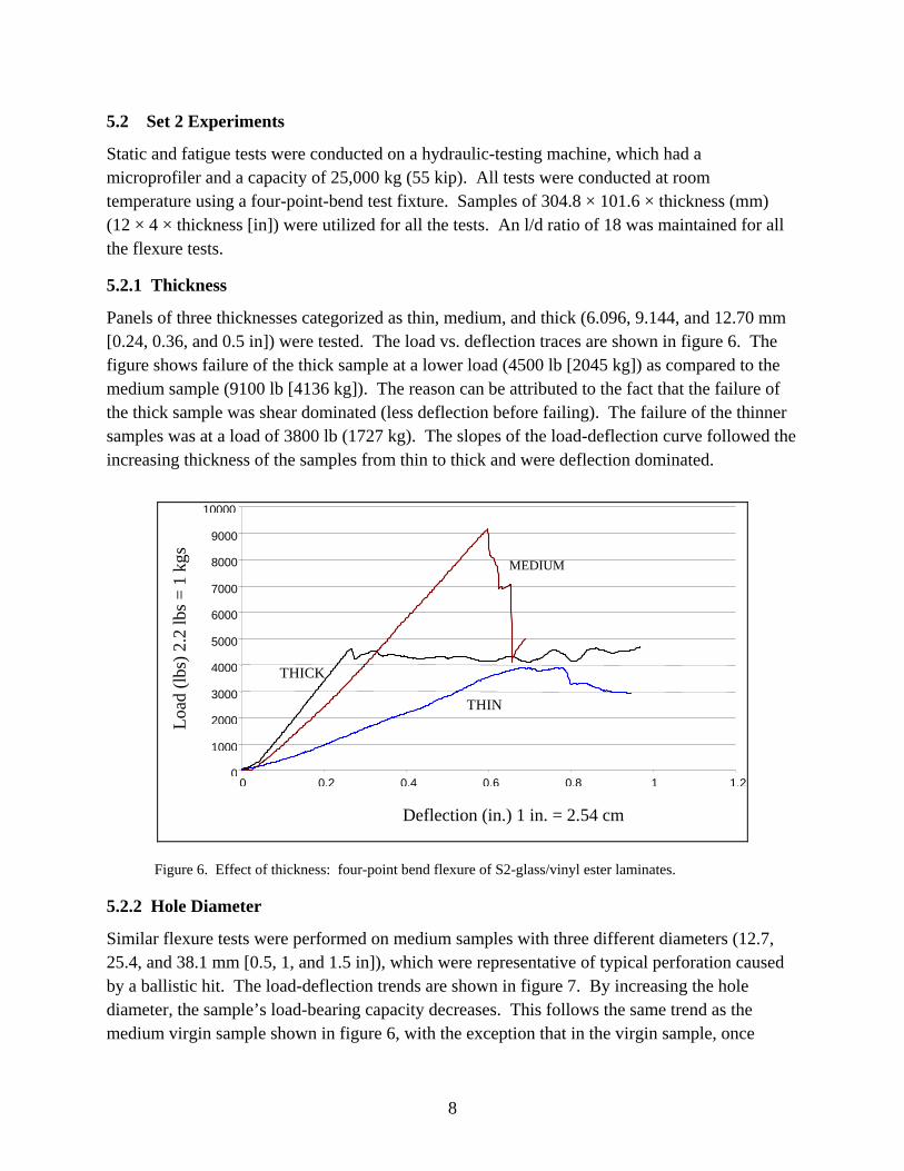
Panels of three thicknesses categorized as thin, medium, and thick (6.096, 9.144, and 12.70 mm [0.24, 0.36, and 0.5 in]) were tested. The load vs. deflection traces are shown in figure 6. The figure shows failure of the thick sample at a lower load (4500 lb [2045 kg]) as compared to the medium sample (9100 lb [4136 kg]). The reason can be attributed to the fact that the failure of the thick sample was shear dominated (less deflection before failing). The failure of the thinner samples was at a load of 3800 lb (1727 kg). The slopes of the load-deflection curve followed the increasing thickness of the samples from thin to thick and were deflection dominated.
0
1000
2000
3000
4000
5000
6000
7000
8000
9000
10000
0 0.2 0.4 0.6 0.8 1 1.2
MEDIUM
THICK
THIN
Loa
d (l
bs)
2.2
lbs
= 1
kgs
Deflection (in.) 1 in. = 2.54 cm
Figure 6. Effect of thickness: four-point bend flexure of S2-glass/vinyl ester laminates.
5.2.2 Hole Diameter
Similar flexure tests were performed on medium samples with three different diameters (12.7, 25.4, and 38.1 mm [0.5, 1, and 1.5 in]), which were representative of typical perforation caused by a ballistic hit. The load-deflection trends are shown in figure 7. By increasing the hole diameter, the sample’s load-bearing capacity decreases. This follows the same trend as the medium virgin sample shown in figure 6, with the exception that in the virgin sample, once

9
Figure 7. Effect of hole diameter: four-point bend flexure of S2-glass/vinyl ester laminates.
failure initiates, the load drops suddenly. Because of higher deflection in the samples with the holes, the load drop is not as drastic as that of the virgin sample, even after the initial crack.
5.3 Fatigue Tests
The flexural fatigue tests were performed in a load control mode on a four-point bend fixture using a 2-Hz frequency sinusoidal waveform (stress ration R = 0.1). The reason for choosing the flexural fatigue study was that it represents realistic loading conditions used by armored vehicles while traversing a terrain. The temperature effects that arise during fatigue were neglected in the tests. All fatigue data has been generated at a load level of 65% of the maximum load of a sample of the corresponding thickness. Table 1 represents the fatigue test data in terms of the peak-deflection change (deflection at maximum cyclic compression load) of the sample as a function of number of cycles. As failure approaches, the deflection increases due to stiffness degradation. This is an indication of impending failure.
This report outlines studies only on the thin samples (6.3 mm [0.24 in] thick). Sample types included (a) the virgin, (b) the virgin with carbon/epoxy doubler ply, (c) idealized damage (clean hole), (d) an unfilled hole covered by doubler ply on either side, (e) only a microballoon/epoxy plug, and (f) a microballoon/epoxy plug with doubler ply.
0
1000
2000
3000 4000
5000
6000
7000
8000
9000
10000
0 0.1 0.2 0.3 0.4 0.5 0.6 0.7 0.8 0.9
0.5”
1.0”
1.5”
Deflection (in) 1 in = 2.54 cm (9.144 mm (0.36 in) thick)
Loa
d (l
b) 2
.2 lb
= 1
kg

10
Table 1. Summary of fatigue tests on samples with hole.
Hole Diameter
mm (in)
Maximum Deflection
mm (in)
No. of Cycles
d/b Ratioa
N/Nvirgin
b
Virgin 9.47 (0.373) 42,400 0 1 12.7 (0.5) 9.99 (0.393) 16,100 0.125 0.424 25.4 (1.0) 14.60 (0.575) 15,800 0.250 0.420 38.1 (1.5) 12.95 (0.51) 15,500 0.370 0.419
ad/b = ratio of width-to-hole diameter. bNvirgin: cycles to failure of virgin panel.
5.3.1 Effect of Hole
Figure 8 represents the fatigue response for the samples with holes of different diameters as a function of number of cycles to failure. As seen from the figure, the virgin sample tends to deflect less due to being stiffer, and its fatigue life is about 135% more, compared to the sample with a 0.5-in-diameter hole. The hole results in reduced stiffness. The damage is in the form of initiation of microdelaminations on the compression side (much like those observed in the static tests) which propagates with the increasing number of fatigue cycles. The cracks originated from the hole on the top surface with certain orientation (15) to the breadthwise axis of the sample. In the case of the 38.1-mm (1.5-in)-diameter hole (the worst case scenario), the initial cracks were seen as early as the 600th cycle and, subsequently, more cracks appeared at regular intervals, which are evident by the fluctuation in the amount of deflection. A similar damage-progression trend was followed by all the notched samples. In the case of the virgin samples, the initial crack was seen after 36,000 cycles, following a steady increase in the deflection level. The cracks in the virgin sample originated between one of the loading arms and the support. The damage was predominantly caused by shearing around the support locations and by delamination. For at least three virgin samples tested, the onset of failure occurred around the supports. For the samples with the hole, the damage was primarily caused by compression failure surrounding the hole.
5.3.2 Effect of Carbon/Epoxy Ply Doubler
Figure 9 represents the fatigue response of the samples with an unfilled hole with a single ply of carbon/epoxy doubler. This case was considered to investigate the role of the doubler in the fatigue response. The results are also compared to the virgin panel and a virgin panel bonded to a similar doubler. Table 2 summarizes the fatigue results for this category. The doubler plies (without plugging the hole) increased the fatigue life over non-doubler test results by 100% for a 12.7-mm hole, 57.2% for a 25.4-mm hole, and 21.91% for a 38.1-mm hole. The double ply is an effective stress transfer design. The failure in terms of matrix whitening and microdelmaination originates within the edges of the hole and propagates across the width of the sample.

11
Figure 8. Effect of hole: deflection vs. number of cycles.
0
0.1
0.2
0.3
0 10000 20000 30000 40000 50000 60000
1
5 4 3
2 0.4
0.5
0.6
0.7
0.8
Def
lect
ion
(in.)
1 in
. = 2
.54
cm
Number of Cycles (N)
Figure 9. Fatigue tests—effect of carbon/epoxy doubler (unfilled hole): (1) virgin, (2) virgin with doubler ply, (3) 12.7-mm hole with doubler, (4) 25.4-mm hole with doubler, and (5) 38.1-mm hole with doubler.
0
0.1
0.2
0.3
0.4
0.5
0.6
0.7
0 10000 20000 30000 40000 50000
Virgin 0.5”
1.5”
1.0”
Def
lect
ion
(in.
) 1i
n.=
2.54
cm
Number of Cycles (N)

12
Table 2. Summary of fatigue tests: carbon/epoxy ply doubler.
Hole Diameter
(in)
Maximum Deflection
mm (in)
No. of Cycles
d/b Ratioa
N/Nvirgin
b
Virgin 9.47 (0.373) 42,400 0 1 Virgin + doubler ply 11.43 (0.45) 51,700 0 1.219 0.5 in + doubler ply 17.01 (0.67) 36,000 0.125 0.849 1.0 in + doubler ply 17.52 (0.69) 28,000 0.250 0.660 1.5 in + doubler ply 13.20 (0.656) 21,700 0.370 0.512
Note: 1 in = 25.4 mm. ad/b = ratio of width-to-hole diameter. bNvirgin: cycles to failure of virgin panel.
5.3.3 Effect of Microballoon/Epoxy
In this case, the samples were plugged with the microballoon/epoxy mixture, without the use of the doubler ply. This was done to ascertain the fatigue life in the absence of the doubler. Figure 10 represents the fatigue response of the samples. Table 3 summarizes the results from the tests. Plugging the hole with only the microballoon/epoxy increases the fatigue life, as compared to the samples with the clean hole. For the sample with the 12.7-mm (0.5-in-diameter) hole, the fatigue life increase is 100.05%. For the 25.4-mm (1-in) hole sample, the increase is 37.07%, as compared to the respective clean hole samples. These tests demonstrated that the use of a doubler was more effective in distributing the compressive stresses as the hole diameter increases. For the 12.7-mm hole, either repair treatment yielded a comparable number of cycles to failure, ~36,000. Failure was across the sample width originating from the hole.
0
0.1
0.2
0.3
0.4
0.5
0.6
0.7
0.8
0 10000 20000 30000 40000 50000
1
23
Number of Cycles (N)
Deflection (in.) 1 in. = 2.54
cm
Figure 10. Fatigue tests—microballoon/epoxy plugs: (1) virgin, (2) 12.7-mm hole, and (3) 25.4-mm hole. Data for 38.1-mm hole was not available.

13
Table 3. Summary of fatigue tests: microballoon/epoxy plug.
Hole Diameter
mm (in)
Maximum Deflection
mm (in)
No. of Cycles
d/b Ratioa
N/Nvirgin
b
Virgin 9.47 (0.373) 42,400 0 1 12.7 (0.5) 17.17 (0.676) 36,101 0.125 0.850 25.4 (1.0) 18.89 (0.744) 24,400 0.250 0.575
Note: data for the 38.1-mm (1.5-in) hole is not available. ad/b = ratio of width-to-hole diameter. bNvirgin: cycles to failure of virgin panel.
5.3.4 Microballoon/Epoxy-Plugged Hole With Carbon/Epoxy Ply Doubler
Based on the results of doubler and microballoon fatigue tests (i.e., the microballoon/epoxy and the carbon/epoxy ply doubler), the text matrix was extended to include a combined repair test for the microballoon/epoxy plug and the doubler. Figure 11 compares the fatigue response of the samples. Table 4 summarizes the test results. There was a 158% increase in the fatigue life for the repaired samples with the 12.7-mm hole, 153.9% for the 25.4-mm hole, and 163.25% for the 38.1-mm hole, in comparison to the clean hole samples. The initial crack propagation started well after 6000 cycles, and the cracks were seen to stabilize after initial flexing. These tests demonstrate that the role of both constituents is effective in enhancing the repair. The microballoon/epoxy plug provides the stress continuity, while the doubler supports the compression side stresses. In all these tests, the role of the tensile side doubler was minimal, as it snapped open within a few hundred cycles, while the compression side doubler remains well bonded through failure. Failure in these samples originated through a microcrack formation around the repair area and progressed across the width of the specimen at the repair location.
0
0.1
0.2
0.3
0.4
0.5
0.6
0.7
0.8
0 10000 20000 30000 40000 50000 60000
1
2
4
3
Deflectio
n (in.) 1 in =2.54 cm
Number of Cycles
Figure 11. Fatigue tests—carbon/epoxy doubler + microballoon/epoxy plug: (1) virgin, (2) 12.7-mm hole, (3) 25.4-mm hole, and (4) 38.1-mm hole.

14
Table 4. Summary of fatigue tests: carbon/epoxy doubler with microballoon/epoxy plug.
Hole Diameter
mm (in)
Maximum Deflection
mm (in)
No. of Cycles
d/b Ratioa
N/Nvirgin
b
Virgin 9.47 (0.373) 42,400 0 1 12.7 (0.5) 16.2 (0.64) 46,100 0.125 1.09 25.4 (1.0) 17.14 (0.675) 47,400 0.250 1.06 38.1 (1.5) 17.27 (0.68) 49,000 0.370 1.15
ad/b = ratio of width-to-hole diameter. bNvirgin: cycles to failure of virgin panel.
6. Summary
S2-glass/vinyl ester composite panels were processed using an affordable VARTM technique. An idealized damage state representing the clean perforation of a projectile was assumed. Simple repair strategies such as plugging and covering the damage with doubler ply were undertaken to ascertain the flexure response following the repair. The following points may be summarized:
• The static and fatigue responses were directly proportional to the size of the hole. Deflection increased in correspondence with the hole diameter. Flexural failure was dominant on the compression side. The failure originated from the notch and resulted in a weakened matrix and microdelamination growth across the width of the sample.
• For repair implemented with the constituents (i.e., plug only and doubler only, with an increase in the hole diameter), the repair implemented by the doubler increased the fatigue life over that of the plug-only treatment. This suggests that the compression side doubler provides effective stress redistribution during flexural fatigue. In the context of the 25.4-mm hole, the “doubler only” provided a 57% increase in fatigue life, and the “plug only” yielded a 37% improvement over the “clean hole” condition. For the smaller hole size (12.7-mm diameter), both treatments yielded comparable fatigue lives.
• A combination repair treatment involving the plug and the use of doubler ply (particularly on the compression side) provided the best results in terms of fatigue life restoration. In the three-hole diameters studied in this work, the fatigue lives of the repaired samples exceeded that of the virgin samples by an average of 10%.
These experiments demonstrated that simple repair techniques could be implemented in a practical manner to restore the fatigue performance of VARTM laminates. Further studies are underway to understand the role of the repair strategies and repair on impact-induced delamination damage.

15
7. References
1. Pike, T.; McArthur, M.; Schade, D.; Schade, M. Low-Cost Fabrication of Advanced Polymeric Composites by Resin Transfer Molding. Proceedings of the 28th International SAMPE Technical Conference, Seattle, WA, 1996; pp 374–380.
2. Monib, A. M.; Gillespie, J. W., Jr. Damage Tolerance of Composite Laminates Subjected to Ballistic Impact. Proceedings of ANTEC 98, Atlanta, GA, 1998; pp 1463–1467.
3. Huang, X. J.; Gillespie, J. W., Jr.; Bogetti, T. Process-Induced Stress for Woven Fabric Thick Section Composite Structures. Composite Structures 2000, 3 (49), 303–312.
4. Bernetich, K. R.; Gillespie, J. W., Jr.; Fink, B. K. Improved Damage Tolerant Armor Via Stitching and Co-Injection Resin Transfer Molding; Vizzini, A. N., Ed.; Proceedings of the American Society for Composites 13th Technical Conference, Baltimore, MD, 1998; pp 1491–1497.
5. Abrate, S. Impact on Laminated Composite Materials. Applied Mechanics Review 1991, 44 (4), 155–190.
6. Burns, B. P.; Hoppel, C. P. R.; Newill, J. F.; Burton, L. W.; Tzeng, J. T.; Bender, J. M.; Drysdale, W. H. An Army Perspective on Composite Materials. Proceedings of the American Society for Composites, 14th Technical Conference; Whitney, J. M., Ed.; Dayton, OH, 1999; pp 223–232.
7. Schwartz, M. M. Composite Materials: Properties, Nondestructive Testing, and Repair; Prentice Hall: Upper Saddle River, NJ, 1996.
8. ASM International. Engineered Materials Handbook: Adhesives and Sealants; CRC Press: Cleveland, OH, 1990; Vol. 3, pp 625–630.
9. Chabot, K. A.; Brescia, J. A. Evaluation of Primers for Adhesively Bonded Aircraft Repair. 25th International SAMPE Technical Conference, Anaheim, CA, 1993; pp 200–211.
10. Mehrkam, P.; Cochran, R.; Trabocco, R. Adhesive for Composite Repair Applications. 25th International SAMPE Technical Conference, Anaheim, CA, 1993; pp 212–221.
11. Xiao, X. R.; Hoa, S. V.; Street, K. N. Composites: Design, Manufacture, and Application; Tsai, S. W., Springer G. S., Eds.; Proceedings of 8th International Conference on Composite Materials, Honolulu, HI, 1991.
12. Davies, P.; Cantwell, W. J.; Jar, P.-Y.; Bourban, P. E.; Zysman, V.; Kaush, H. H. Measurement of Initiation Values of GIc in IM6/Peek Composites. Composites 1991, 22 (6), 425–431.
13. Zimmerman, K.; Liu, D. Geometrical Parameters in Composite Repair. Journal of Composite Materials 1995, 29 (11), 1473–1487.

NO. OF COPIES ORGANIZATION
16
1 DEFENSE TECHNICAL (PDF INFORMATION CTR only) DTIC OCA 8725 JOHN J KINGMAN RD STE 0944 FORT BELVOIR VA 22060-6218 1 DIRECTOR US ARMY RESEARCH LAB IMNE ALC HRR 2800 POWDER MILL RD ADELPHI MD 20783-1197 1 DIRECTOR US ARMY RESEARCH LAB RDRL CIM L 2800 POWDER MILL RD ADELPHI MD 20783-1197 1 DIRECTOR US ARMY RESEARCH LAB RDRL CIM P 2800 POWDER MILL RD ADELPHI MD 20783-1197
ABERDEEN PROVING GROUND 1 DIR USARL RDRL CIM G (BLDG 4600)

NO. OF NO. OF COPIES ORGANIZATION COPIES ORGANIZATION
17
2 US ARMY RSRCH OFC D STEPP T DOLIGALSKI PO BOX 12211 RESEARCH TRIANGLE PARK NC 27709-2211 1 DARPA TACTICAL TECHLGY OFC S WALKER 3701 N FAIRFAX DR ARLINGTON VA 22203-1714 1 DARPA DEFNSE SCI OFC W COBLENZ 3701 N FAIRFAX DR ARLINGTON VA 2203-1714 1 COMMANDER US ARMY MATERIEL CMD AMSMI INT 9301 CHAPEK RD FORT BELVOIR VA 22060-5527 1 COMMANDER US ARMY TACOM PM COMBAT SYS SFAE GCS CS 6501 ELEVEN MILE RD WARREN MI 48397-5000 1 PEO GCS SFAE GCS BCT MS 325 WARREN MI 48397-5000 1 COMMANDER US ARMY TACOM PEO CS & CSS PM LIGHT TACTICAL VEHIC SFAE CSS LT M114 6501 ELEVEN MILE RD WARREN MI 48397-5000 1 US ARMY TACOM AMSRD TAR R D TEMPLETON MS 263 6501 E ELEVEN MILE RD WARREN MI 48397-5000
1 NSWC CARDEROCK DIV R PETERSON CODE 28 9500 MACARTHUR BLVD WEST BETHESDA MD 20817-5700 1 NSWC CARDEROCK DIV R CRANE CODE 2802 9500 MACARTHUR BLVD WEST BETHESDA MD 20817-5700 3 UNIV OF ALABAMA AT BIRMINGHAM T JACKSON U VAIDYA G JANOWSKI BEC 254 1530 THIRD AVE SOUTH BIRMINGHAM AL 35294-4461 1 NORTH DAKOTA STATE UNIV C ULVEN DOLVE 111 PO BOX 5285 FARGO ND 58105 1 VIRGINIA TECH S R TURNER 2 DAVIDSON HALL 0201 BLACKSBURG VA 24061 1 UNIV OF DELAWARE J DEITZEL 219 COMPOSITES SCI LAB NEWARK DE 19716-3144 1 DREXEL UNIV G PALMESE 3141 CHESTNUT ST PHILADELPHIA PA 19104 1 TICONA D EMERSON 2600 OPDYKE RD AUBURN HILLS MI 48326

NO. OF COPIES ORGANIZATION
18
ABERDEEN PROVING GROUND 1 USAMSAA P DEITZ BLDG 392 APG MD 21005 17 DIR USARL RDRL LOA F M ADAMSON RDRL SL R COATES RDRL WM L BURTON J SMITH RDRL WMB M ZOLTOSKI RDRL WMB C J GARNER RDRL WMM J BEATTY S MCKNIGHT RDRL WMM A M VANLANDINGHAM RDRL WMM B A FRYDMAN T BOGETTI RDRL WMM C M MAHER RDRL WMM D B CHEESEMAN J SANDS RDRL WMT P BAKER RDRL WMT A S SCHOENFELD RDRL WMT E A NIILER