Flexural Analysis of Prestressed Concrete Monoblock...
15
Manuscript for Annual Meeting Compendium of Papers 1 2 Flexural Analysis of Prestressed Concrete Monoblock Crossties: 3 Comparison of Current Methodologies and Sensitivity to Support Conditions 4 5 TRB 15-2924 6 Transportation Research Board 94 th Annual Meeting 7 Submitted: November 15, 2014 8 9 10 Henry E. Wolf 1,2 , Steve Mattson 3 , J. Riley Edwards 2 , Marcus S. Dersch 2 , and 11 Christopher P. L. Barkan 2 12 13 14 Rail Transportation and Engineering Center – RailTEC 2 15 Department of Civil and Environmental Engineering 16 University of Illinois at Urbana-Champaign 17 205 N. Mathews Ave., Urbana, IL 61801 18 19 Voestalpine Nortrak, Inc. 3 20 1803 Pacific Avenue 21 Cheyenne, WY 82007 22 23 24 5475 Words, 3 Tables, 4 Figures = 7225 Total Word Count 25 26 Henry E. Wolf 1 Steve Mattson J. Riley Edwards (217) 369-2683 (509) 220-6837 (217) 244-7417 [email protected] [email protected] [email protected] Marcus S. Dersch Christopher P.L. Barkan (217) 333-6232 (217) 244-6338 [email protected] [email protected] 1 Corresponding author TRB 2015 Annual Meeting Paper revised from original submittal.
Transcript of Flexural Analysis of Prestressed Concrete Monoblock...
Manuscript for Annual Meeting Compendium of Papers 1
2
Flexural Analysis of Prestressed Concrete Monoblock Crossties: 3
Comparison of Current Methodologies and Sensitivity to Support Conditions 4
5
TRB 15-2924 6
Transportation Research Board 94th Annual Meeting 7
Submitted: November 15, 2014 8
9
10
Henry E. Wolf1,2, Steve Mattson3, J. Riley Edwards2, Marcus S. Dersch2, and 11 Christopher P. L. Barkan2 12
13
14 Rail Transportation and Engineering Center – RailTEC
2 15
Department of Civil and Environmental Engineering 16 University of Illinois at Urbana-Champaign 17
205 N. Mathews Ave., Urbana, IL 61801 18 19
Voestalpine Nortrak, Inc.3 20
1803 Pacific Avenue 21 Cheyenne, WY 82007 22
23 24
5475 Words, 3 Tables, 4 Figures = 7225 Total Word Count 25
26 Henry E. Wolf
1 Steve Mattson
J. Riley Edwards
(217) 369-2683 (509) 220-6837 (217) 244-7417
[email protected] [email protected] [email protected]
Marcus S. Dersch
Christopher P.L. Barkan
(217) 333-6232 (217) 244-6338
[email protected] [email protected]
1 Corresponding author
TRB 2015 Annual Meeting Paper revised from original submittal.

Wolf et al. TRB 15-2924 1
ABSTRACT 1 Throughout the international railway community, many methods have been developed to analyze the 2 flexural demand of concrete crossties. The investigation described in this paper serves to clarify and 3 improve upon the current language found in the American Railway Engineering and Maintenance-of-Way 4
Association (AREMA) recommended practices for the design of prestressed concrete monoblock 5 crossties. Specifically, this paper will focus on how changes in support condition assumptions affect the 6 flexural analysis of the crosstie. The current flexural analysis methodologies contained in AREMA 7 Chapter 30, EuroNorm (EN) 13230, International Union of Railways (UIC) 713R, and Australian 8 Standard (AS) 1085.14 will be explained and compared. To investigate the theoretical bending moments 9 experienced by the crosstie under varying support conditions, a linear-elastic crosstie analysis model was 10 developed. This model was used to perform a parametric study to determine the sensitivity of the crosstie 11 to changes in ballast reaction along the crosstie. The results of this parametric study were compared to 12
existing design recommendations to find allowable levels of ballast reaction that can occur beneath the 13 crosstie before failure is expected. This model was also used to calculate theoretical bending moment 14 values under ballast reactions measured in the field. Since the theoretical rail seat bending moments 15 exceeded current design recommendations and the crossties did not experience any flexural cracking, it 16 suggests that the tested crossties were either over-designed or behaving as a deep beam. Based on the 17 results of these analyses, recommendations to improve current design and maintenance practices for 18 prestressed concrete crossties will be presented.19
TRB 2015 Annual Meeting Paper revised from original submittal.

Wolf et al. TRB 15-2924 2
INTRODUCTION AND BACKGROUND 1 Throughout the world, the majority of railroad track infrastructure is supported by ballast. A ballasted 2 track system typically consists of rail, fastening systems, crossties, ballast, sub-ballast, and subgrade. The 3 most commonly used material for crossties in the United States is timber, which is used in about 90-95% 4
of the crossties in service. Concrete is the second most common material for crossties, making up most of 5 the remaining 5-10%. Steel and composite crossties are also used, but they make up a negligible share of 6 the number of crossties in service. Typically, concrete crossties are used in the most demanding service 7 conditions (e.g. high curvature, steep grades, heavy tonnage, high speed passenger traffic, etc.) 8
As a material, concrete is very weak in tension, but very strong in compression. Because of this, 9 concrete crossties must be held in compression, or “prestressed”, with tensioned steel. This can be 10 achieved by tensioning steel wires or strands before or after the concrete is cast; members made this way 11 are referred to as “pre-tensioned” and “post-tensioned”, respectively. Pre-tensioning is the more common 12
practice for the manufacture of prestressed concrete crossties in the United States. Prestressing 13 significantly increases concrete’s flexural strength, ductility, and resistance to cracking. With this 14 improved strength and ductility, prestressed concrete crossties can withstand the demanding dynamic 15 loading environment imparted by passing trains. 16
The primary purpose of the crosstie is to maintain track geometry (e.g. gauge, cross level, etc.) 17 and to transfer applied loads to the track substructure. When a concrete crosstie supported on ballast is 18 loaded vertically, the load is transferred from the wheel to the track system through the rail, fastening 19
system, crosstie, ballast, sub-ballast, and subgrade. The ballast support conditions play a critical role in 20 the type and severity of bending that the crosstie will experience under loading from a passing train. The 21 ballast support is affected by a variety of factors that include loading during train operations, tamping, 22 fouling, and voids. 23
According to a survey of railroads, concrete crosstie manufacturers, and researchers from around 24 the world, crosstie cracking from center binding was ranked as the third most critical problem with 25 concrete crossties (1). North American respondents considered center cracking to be slightly less critical 26
than their international counterparts, ranking it as the fifth most critical issue in concrete crossties. 27 However, North American respondents ranked cracking from dynamic loads as the third most critical 28 issue, one place ahead of international respondents. 29 30 CURRENT FLEXURAL DESIGN METHODOLOGY 31 The structural design process consists of two steps. First, an analysis is performed to estimate the 32 demand (i.e. flexure, shear, etc.) that a structural element is expected to undergo in its lifetime. Second, 33 the element is designed to meet or exceed the demand found in the analysis. Currently, design standards 34
produced by organizations such as the American Railway Engineering and Maintenance-of-Way 35 Association (AREMA) (2), EuroNorm (EN) (3), International Union of Railways (UIC) (4), and 36 Australian Standard (AS) (5) only provide formal recommendations on the analysis portion of the 37 structural design process. In this section, an explanation and comparison of the analysis methodologies 38 proposed by AREMA, EN, UIC, and AS will be provided. A clear understanding of these different 39 methodologies and their respective assumptions is critical in improving the current structural design 40 process for prestressed concrete monoblock crossties. 41
42 American Railway Engineering and Maintenance-of-way Association (AREMA C30) 43 The current AREMA method for concrete crosstie flexural analysis is a factored approach that is 44 dependent on crosstie length, crosstie spacing, annual tonnage, and train speed. Design bending moments 45 are given for four key locations on the crosstie: rail seat positive (MRS+), rail seat negative (MRS-), center 46 positive (MC+), and center negative (MC-). To begin, AREMA Figure 30-4-3 is used to determine the 47 factored design bending moment for a given loading condition. By specifying the crosstie spacing and 48
the crosstie length, an unfactored rail seat positive bending moment (B) can be found from AREMA 49 Figure 30-4-3. AREMA Figure 30-4-4 is then used to determine the speed (V) and tonnage factors (T), 50 which are based on expected track speed and tonnage, respectively. These three values are multiplied 51
TRB 2015 Annual Meeting Paper revised from original submittal.
Wolf et al. TRB 15-2924 3
together using Equation 1. For each figure, linear interpolation can be performed between two specified 1 points to obtain a more accurate factor. 2
3 MRS+ = B × V ×T (1)
4 where, MRS+ = factored rail seat positive bending moment (kip-in) 5
B = unfactored rail seat positive bending moment (kip-in) 6 V = speed factor 7 T = tonnage factor 8 Once the design rail seat positive bending moment is determined, it is multiplied by other factors to 9 determine design bending moments at the three other key locations. The factors are based on crosstie 10 length and can be linearly interpolated (AREMA Table 30-4-1). 11 The origins of AREMA Figure 30-4-3 are unclear, but a paper by McQueen (6) suggests that the 12 chart is based on an 8’-6” crosstie with 60” rail center-to-center spacing under an 82 kip axle load, as 13
pictured in Figure 1a. The ballast reaction is assumed to be uniform along the entire length of the 14 crosstie. The rail seat load is computed according to the AREMA recommendation, using Equation 2 15 below. 16 17 R = WL×DF × (1 + IF) (2)
18 where, R = design rail seat load (kip) 19 WL = unfactored wheel load (kip) 20 DF = distribution factor (from AREMA Figure 30-4-1) 21 IF = impact factor (specified to be 200% by AREMA) 22
Thus, for an 82 kip axle load, 24” crosstie spacing, and 200% impact factor, the design rail seat load is 23 62.1 kips. 24 Because the ballast reaction is assumed to be uniform along the entire crosstie, the reaction can be 25 found by multiplying the design rail seat load by two (to account for both rail seats) and then dividing by 26 the length of the crosstie. So, for a 102” crosstie with a design rail seat load of 62.1 kips, the distributed 27 ballast reaction is 1.22 kips/in. McQueen then calculates the rail seat bending moment by modeling the 28 end of the crosstie to the design rail seat load as a cantilever, using Equation 3 below. 29
30
M =wc2
2
(3)
31 where, M = unfactored rail seat positive bending moment (kip-in) 32 w = distributed ballast reaction (kips/in) 33 c = cantilever length (in) 34
McQueen then applies a 10% factor to account for prestress losses. Most concrete crosstie manufacturers 35 consider prestress losses in their design, meaning this increase of 10% is essentially a safety factor. After 36 this factor is applied, the product is rounded up to the nearest 5 kip-in to get the design rail seat positive 37 bending moment. By applying this safety factor and rounding, the design rail seat positive bending 38 moment proposed by McQueen is 300 kip-in. This value matches the bending moment value given by 39 AREMA Figure 30-4-3 for an 8’-6” crosstie at 24” spacing. 40 This design rail seat positive bending moment is then multiplied by factors in AREMA Table 30-41 4-1 to find values for design bending moments at the other critical regions. For an 8’-6” crosstie AREMA 42
specifies a factor of 0.67 to calculate center negative bending moment. Thus, using the 300 kip-in rail 43 seat positive bending moment, the center negative bending moment is 201 kip-in. For an 8’-6” crosstie 44 with 60” rail center-to-center spacing, this center negative bending moment can be found when the 45 reaction at an 18” center section is reduced 39% (Figure 1b). These support conditions were found 46 considering the 10% safety factor. It is also important to remember that these design bending moments 47
TRB 2015 Annual Meeting Paper revised from original submittal.
Wolf et al. TRB 15-2924 4
values would then be multiplied by a tonnage and train speed factor, which could increase the values by 1 as much as a factor of 1.32. 2 3 EuroNorm (EN 13230-1) / International Union of Railways (UIC 713R) 4
EN 13230-1 states that the purchaser must specify the design bending moments to the crosstie 5 manufacturer. In Annex E, it defers the analysis of design bending moments to UIC 713R. The UIC 6 713R method of analysis is dependent on crosstie length, crosstie spacing, axle load, rail pad attenuation, 7 and train speed. Like AREMA, UIC also provides a pair of safety factors, one to account for “variation in 8 crosstie reaction due to support faults” and another to account for “irregularity in the support along the 9 crosstie.” 10
As seen previously in McQueen’s method, the design rail seat load must first be calculated in 11 order to perform the flexural analysis of the crosstie. The crosstie is assumed to be under a “newly 12
tamped” condition, with the ballast reaction occurring symmetrically about the rail seat load (Figure 1c). 13 Equation 4 below is used to calculate the design rail seat load according to UIC 713R. 14
15
R =Q0
2(1+ γpγv)γdγrγi
(4)
16 where, R = design rail seat load (kip) 17 Q0 = unfactored axle load (kip) 18 γp = rail pad attenuation factor (UIC 713R recommends 1.0 for low attenuation) 19 γv = speed factor (UIC 713R recommends 0.5 for speeds under 125 mph) 20 γd = distribution factor (UIC 713R recommends 0.5 for crosstie spacing under 25.6”) 21
γr = reaction support fault safety factor (UIC 713R recommends 1.35) 22
γi = support irregularity safety factor (UIC 713R recommends 1.6) 23 Thus, for an 82 kip unfactored axle load and the UIC 713R-recommended factors, the design rail seat load 24 found according to UIC 713R is 66.4 kips, or 7% greater than the AREMA recommendation. 25 Next, UIC 713R calculates the rail seat positive bending moment for the crosstie with Equation 5. 26 27
MRS+ =R
4(c −
f
2−h
2)
(5)
28 where, MRS+ = design rail seat positive bending moment (kip-in) 29
R = design rail seat load (kip) 30 c = cantilever arm (kip) 31 f = width of rail base (in) 32 h = depth of crosstie (in) 33
There are several assumptions made in this equation. First, the rail seat load is assumed to be uniformly 34 distributed over the entire width of the rail seat. As seen in research conducted at the University of 35 Illinois at Urbana-Champaign, this assumption is not necessarily valid, especially in the presence of 36 lateral loads and high lateral to vertical (L/V) load ratios (7). The distributed rail seat load causes the 37 moment at the center of the rail seat to be reduced, which is explained in further detail by Freudenstein 38 (8). Additionally, UIC 713R assumes that the crosstie behaves as a deep beam, transferring the rail seat 39 load in a compressive field spreading at a 45 degree angle to the neutral axis of the crosstie (assumed in 40
the above equation to be one-half of the crosstie height). This means that for a 9” deep crosstie 41 supporting a rail seat 6” wide, the rail seat load is distributed over a length of 15”. This causes a 42 significant reduction in moment. Thus, for a crosstie of length of 8’-6”, depth of 9”, and rail center-to-43 center spacing of 60”, under an 82 kip unfactored axle load on 6” rail seats the design rail seat positive 44 bending moment per UIC 713R is 224 kip-in, a 25% reduction from the AREMA recommendation. 45 UIC 713R calculates the center negative bending moment using three methods. First, Equation 6 46 can be used for a crosstie with constant width. Two alternative equations can be used for crossties with 47
TRB 2015 Annual Meeting Paper revised from original submittal.
Wolf et al. TRB 15-2924 5
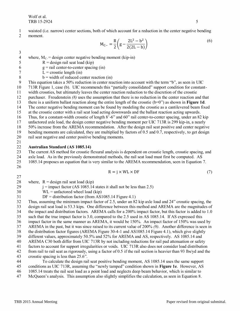
waisted (i.e. narrow) center sections, both of which account for a reduction in the center negative bending 1 moment. 2
MC− =R
2(g−
2L2 − b2
2(2L − b))
(6)
3 where, MC- = design center negative bending moment (kip-in) 4
R = design rail seat load (kip) 5 g = rail center-to-center spacing (in) 6 L = crosstie length (in) 7 b = width of reduced center reaction (in) 8 This equation takes a 50% reduction in center reaction into account with the term “b”, as seen in UIC 9 713R Figure 1, case (b). UIC recommends this “partially consolidated” support condition for constant-10 width crossties, but ultimately leaves the center reaction reduction to the discretion of the crosstie 11
purchaser. Freudenstein (8) uses the assumption that there is no reduction in the center reaction and that 12 there is a uniform ballast reaction along the entire length of the crosstie (b=0”) as shown in Figure 1d. 13 The center negative bending moment can be found by modeling the crosstie as a cantilevered beam fixed 14 at the crosstie center with a rail seat load acting downwards and the ballast reaction acting upwards. 15 Thus, for a constant-width crosstie of length 8’-6” and 60” rail center-to-center spacing, under an 82 kip 16 unfactored axle load, the design center negative bending moment per UIC 713R is 299 kip-in, a nearly 17 50% increase from the AREMA recommendation. After the design rail seat positive and center negative 18
bending moments are calculated, they are multiplied by factors of 0.5 and 0.7, respectively, to get design 19 rail seat negative and center positive bending moments. 20
21 Australian Standard (AS 1085.14) 22 The current AS method for crosstie flexural analysis is dependent on crosstie length, crosstie spacing, and 23 axle load. As in the previously demonstrated methods, the rail seat load must first be computed. AS 24 1085.14 proposes an equation that is very similar to the AREMA recommendation, seen in Equation 7. 25 26
R = j ×WL ×DF (7) 27
where, R = design rail seat load (kip) 28 j = impact factor (AS 1085.14 states it shall not be less than 2.5) 29
WL = unfactored wheel load (kip) 30 DF = distribution factor (from AS1085.14 Figure 4.1) 31 Thus, assuming the minimum impact factor of 2.5, under an 82 kip axle load and 24” crosstie spacing, the 32 design rail seat load is 53.3 kips. One difference between this method and AREMA are the magnitudes of 33 the impact and distribution factors. AREMA calls for a 200% impact factor, but this factor is added to 1.0 34
such that the true impact factor is 3.0, compared to the 2.5 used in AS 1085.14. If AS expressed this 35 impact factor in the same manner as AREMA, it would be 150%. An impact factor of 150% was used by 36 AREMA in the past, but it was since raised to its current value of 200% (9). Another difference is seen in 37 the distribution factor figures (AREMA Figure 30-4-1 and AS1085.14 Figure 4.1), which give slightly 38 different values, approximately 50.5% and 52% for AREMA and AS, respectively. AS 1085.14 and 39 AREMA C30 both differ from UIC 713R by not including reductions for rail pad attenuation or safety 40 factors to account for support irregularities or voids. UIC 713R also does not consider load distribution 41 from rail to rail seat as rigorously, using a factor of 0.5 if the rail section is heavier than 93 lbs/yd and the 42
crosstie spacing is less than 25.6”. 43 To calculate the design rail seat positive bending moment, AS 1085.14 uses the same support 44
conditions as UIC 713R, assuming the “newly tamped” condition shown in Figure 1e. However, AS 45 1085.14 treats the rail seat load as a point load and neglects deep beam behavior, which is similar to 46 McQueen’s analysis. This assumption also slightly simplifies the calculation, as seen in Equation 8. 47
TRB 2015 Annual Meeting Paper revised from original submittal.

Wolf et al. TRB 15-2924 6
1
MRS+ =R(L − g)
8
(8)
2 where, MRS+ = design rail seat positive bending moment (kip-in) 3
R = design rail seat load (kip) 4 g = rail center-to-center spacing (in) 5 L = crosstie length (in) 6 Thus, for a crosstie of length of 8’-6” and rail center-to-center spacing of 60”, under an 82 kip unfactored 7 axle load, the design rail seat positive bending moment per AS 1085.14 is 280 kip-in, a 7% reduction 8 from the AREMA recommendation and a 25% increase from the UIC recommendation. 9
The AS 1085.14 center negative analysis is very similar to the UIC 713R analysis presented 10
earlier. Both assume uniform ballast reaction along the length of the crosstie, but AS treats the rail seat 11 load as a point load (Figure 1f). As a result, the AS 1085.14 equation for design center negative bending 12 moment (Equation 9), is the same as the UIC 713R equation for design center negative bending moment 13 (Equation 6) when there is no center reaction reduction (b=0”). 14
15
MC− =R(2g− L)
4
(9)
16 where, MC- = design rail seat positive bending moment (kip-in) 17
R = design rail seat load (kip) 18
g = rail center-to-center spacing (in) 19 L = crosstie length (in) 20 Thus, for a crosstie of length 8’-6” and 60” rail center-to-center spacing, under an 82 kip unfactored axle 21 load the design center negative bending moment per AS 1085.14 is 240 kip-in, a 20% increase from the 22 AREMA recommendation and a 20% reduction from the UIC recommendation. 23
24 FIGURE 1 Support conditions for select design recommendations: 25 (a) AREMA MRS+, (b) AREMA MC-, (c) UIC MRS+, (d) UIC MC-, (e) AS MRS+, (f) AS MC-. 26
TRB 2015 Annual Meeting Paper revised from original submittal.
Wolf et al. TRB 15-2924 7
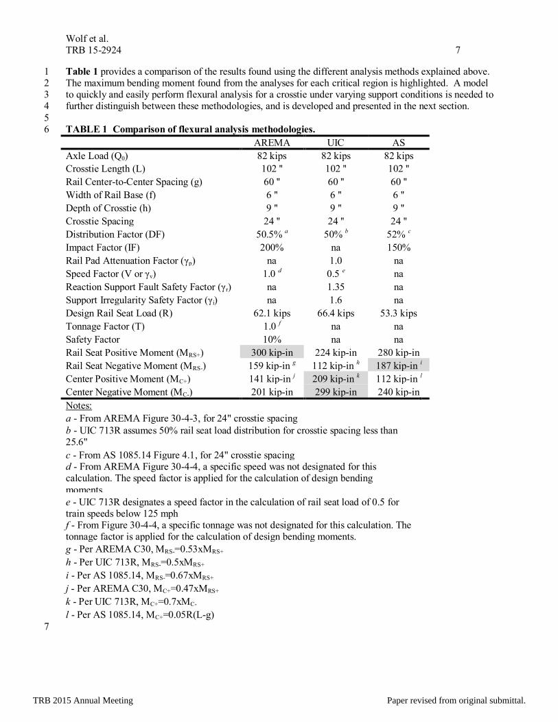
Table 1 provides a comparison of the results found using the different analysis methods explained above. 1 The maximum bending moment found from the analyses for each critical region is highlighted. A model 2 to quickly and easily perform flexural analysis for a crosstie under varying support conditions is needed to 3 further distinguish between these methodologies, and is developed and presented in the next section. 4
5 TABLE 1 Comparison of flexural analysis methodologies. 6
AREMA UIC AS
Axle Load (Q0) 82 kips 82 kips 82 kips
Crosstie Length (L) 102 '' 102 '' 102 ''
Rail Center-to-Center Spacing (g) 60 '' 60 '' 60 ''
Width of Rail Base (f) 6 '' 6 '' 6 ''
Depth of Crosstie (h) 9 '' 9 '' 9 ''
Crosstie Spacing 24 '' 24 '' 24 ''
Distribution Factor (DF) 50.5% a 50% b 52% c
Impact Factor (IF) 200% na 150%
Rail Pad Attenuation Factor (γp) na 1.0 na
Speed Factor (V or γv) 1.0 d 0.5 e na
Reaction Support Fault Safety Factor (γr) na 1.35 na
Support Irregularity Safety Factor (γi) na 1.6 na
Design Rail Seat Load (R) 62.1 kips 66.4 kips 53.3 kips
Tonnage Factor (T) 1.0 f na na
Safety Factor 10% na na
Rail Seat Positive Moment (MRS+) 300 kip-in 224 kip-in 280 kip-in
Rail Seat Negative Moment (MRS-) 159 kip-in g 112 kip-in h 187 kip-in i
Center Positive Moment (MC+) 141 kip-in j 209 kip-in k 112 kip-in l
Center Negative Moment (MC-) 201 kip-in 299 kip-in 240 kip-in
Notes:
a - From AREMA Figure 30-4-3, for 24" crosstie spacing
b - UIC 713R assumes 50% rail seat load distribution for crosstie spacing less than 25.6"
c - From AS 1085.14 Figure 4.1, for 24" crosstie spacing d - From AREMA Figure 30-4-4, a specific speed was not designated for this calculation. The speed factor is applied for the calculation of design bending
moments.
e - UIC 713R designates a speed factor in the calculation of rail seat load of 0.5 for train speeds below 125 mph f - From Figure 30-4-4, a specific tonnage was not designated for this calculation. The tonnage factor is applied for the calculation of design bending moments.
g - Per AREMA C30, MRS-=0.53xMRS+
h - Per UIC 713R, MRS-=0.5xMRS+
i - Per AS 1085.14, MRS-=0.67xMRS+
j - Per AREMA C30, MC+=0.47xMRS+
k - Per UIC 713R, MC+=0.7xMC-
l - Per AS 1085.14, MC+=0.05R(L-g)
7
TRB 2015 Annual Meeting Paper revised from original submittal.

Wolf et al. TRB 15-2924 8
DEVELOPMENT OF LINEAR-ELASTIC CROSSTIE ANALYSIS MODEL 1 In order to better understand the effect of changing support conditions on crosstie bending moments, it 2 was necessary to develop an analytical model. The authors desired to create a model that was easily 3 accessible and simple to use. As such, Microsoft Excel was chosen as the platform for this tool and basic 4
Euler-Bernoulli beam theory was used. 5 To further simplify the analysis, half of the crosstie was modeled as a linear-elastic cantilevered 6 beam. This assumed that the crosstie was symmetrically loaded and supported about the center, and that 7 the loading was quasi-static. The ballast reaction was modeled as a distributed load and the rail seat load 8 was modeled as a point load (as seen in the AREMA and AS analyses). This model was developed for a 9 crosstie with a length of 8’-6” and rail center-to-center spacing of 60”, but can accommodate varying 10 crosstie lengths and rail center-to-center spacings. 11
In order to quickly adjust the ballast reaction, the reaction was split into sections or “bins”. These 12
bins were placed symmetrically about the rail seat load in order to easily simulate different theoretical and 13 experimental ballast reactions. Dividing the rail seat-supported section into six bins was deemed to 14 provide adequate resolution. For an 8’-6” crosstie, this meant that each rail seat bin was 7”. This left a 9” 15 section at the crosstie center, which was split into three bins for consistency and to provide greater 16 resolution at the region expected to be most critical to the center bending moment. Figure 2 shows the 17 set-up of this crosstie model with the ballast reaction split into nine bins. 18
19
20 FIGURE 2 Illustration of linear-elastic crosstie model. 21
22 EFFECT OF SUPPORT CONDITIONS ON CROSSTIE BENDING MOMENTS 23 The goal of the parametric study was to determine the bending moment values that could be experienced 24 by a crosstie under a given rail seat load and different support conditions. First, this problem was 25 bounded by idealizing the ballast reaction as a point load that varies with “x” along the length of the 26 crosstie, as given in Equation 8. This idealization assumes that the entire rail seat load is taken by a single 27 discrete point underneath the crosstie. It would be similar to a crosstie being supported symmetrically 28
about the center by two pieces of ballast. 29 30 MC = −R(
g
2) + Px (8)
31 where, MC = bending moment at crosstie center (kip-in) 32
TRB 2015 Annual Meeting Paper revised from original submittal.

Wolf et al. TRB 15-2924 9
g = rail center-to-center spacing (in) 1 R = design rail seat load (kip) 2
P = ballast reaction (kip) 3 x = location of ballast reaction 4
For a rail seat load of 62.1 kips on a crosstie with length of 8’-6” and a rail center-to-center spacing of 5 60”, the theoretical bending moment extremes at the crosstie center could range from 1304 kip-in to -6 1863 kip-in, where the maximum positive moment occurs when the reaction load occurs at the end of the 7 crosstie and the maximum negative moment occurs when the reaction load occurs at the center of the 8 crosstie. These values are the upper and lower limits of bending moments that could be experienced by 9 the crosstie. However, this method is overly simplified and does not provide realistic support conditions. 10 To more realistically express the ballast reactions seen in track, the percentage of total reaction 11 taken by each bin was modified. To compare the sensitivity of the reaction of each bin on the bending 12
moments, each bin was modified separately, such that the ballast reaction in one bin changed and the 13 ballast reactions in the other eight bins shared the remainder of the reaction equally. For example, if bin 14 A takes 0% of the rail seat load, 100% of the ballast reaction would be shared equally between bins B-I. 15 The rail seat and center bending moments under these conditions are found to be 138 and -497 kip-in, 16 respectively. Similarly, if bin C takes 25% of the rail seat load, the remaining 75% is split equally to bins 17 A, B, and D-I, for a rail seat moment of 262 kip-in and a center moment of -215 kip-in. The complete 18 results of this study are shown in Table 2. The rail seat load used in these analyses was 62.1 kips. 19
20 TABLE 2 Effect of ballast reaction on MRS and MC. 21
Bin A B C D E F G H I
Rail Seat
Moment
(MRS)
(kip-in)
0% 138 207 277 311 311 311 285 285 285
25% 375 319 262 233 233 233 214 214 214
50% 613 430 247 156 156 156 143 143 143
75% 850 541 232 78 78 78 71 71 71
100% 1087 652 217 0 0 0 0 0 0
Center
Moment
(MC)
(kip-in)
0% -497 -428 -358 -289 -220 -151 -210 -198 -187
25% -101 -158 -215 -272 -328 -385 -506 -544 -582
50% 295 113 -70 -253 -436 -618 -804 -891 -978
75% 691 382 74 -235 -544 -853 -1100 -1237 -1374
100% 1087 652 217 -217 -652 -1087 -1397 -1584 -1770
22 From the above table, one can see how the shift in the ballast reaction affects the rail seat and center 23 bending moments. As larger percentages of the ballast reaction are taken by bins closer to the crosstie 24 end (A, B), the rail seat and center bending moments both increase, and vice versa. Shaded cells 25
represent moments that exceed the maximum values found using any of the analysis methods explained 26 previously (Table 1). It is seen that the rail seat bending moment is always positive and is very sensitive 27 to changes in bins A, B, and C (i.e. the distance between the rail seat and the end of the crosstie). This is 28 seen in the very high bending moments when the ballast reaction is concentrated at these bins. As 29 discussed earlier, the magnitude of the center bending moment can be very high for either positive or 30 negative bending. The center experiences its maximum positive bending moments when the ballast 31 reaction is concentrated outside of the rail center-to-center spacing and experiences its maximum negative 32
bending moments when the ballast reaction is concentrated inside of the rail center-to-center spacing. 33 One of the simplest ways to see the sensitivity of a bin is to compare the difference between 34 moments found when the bin takes 0% and 100% of the ballast reaction. For the rail seat bending 35 moment, the most sensitive bin is found to be bin A, where the difference between the moment when 36
TRB 2015 Annual Meeting Paper revised from original submittal.

Wolf et al. TRB 15-2924 10
100% of the ballast reaction occurs in bin A (1087 kip-in) and when 0% of the ballast reaction occurs in 1 bin A (138 kip-in) is 949 kip-in. Since bin A is the free end located the greatest distance from the rail seat 2 load, it has the largest moment arm and the greatest effect on bending at the rail seat. The least sensitive 3 bin for rail seat bending moment is bin C, with a difference in the 0 and 100% reactions of only -60 kip-4
in. This is because it has a smaller moment arm from the rail seat. 5 Continuing this method of comparison to the center bending moment, bin I has the greatest 6 sensitivity, with a difference in the 0 and 100% reactions of -1583 kip-in. As the reaction moves closer to 7 the crosstie center, the distance between the rail seat load and the centroid of the reaction increases, 8 causing greater magnitudes of negative bending. The center bending moment was found to be least 9 affected by changes in bin D, with a difference in the 0 and 100% reactions of only 72 kip-in. 10 When tracking the fairly realistic case of a bin taking 25% of the ballast reaction across the 11 crosstie (from bin A to bin I, down the 25% rows in Table 2), it is clear how quickly center negative 12
bending moments can exceed current design recommendations. As stated by Remennikov et al. (10) and 13 frequently noted by North American concrete crosstie designers, most concrete crossties are overdesigned 14 and have reserve strength. Even so, if a crosstie was designed to meet UIC 713R, the most demanding 15 center negative recommendation, this strength would be exceeded when bins E, F, G, H, or I take 25% or 16 more of the ballast reaction. This shows how even small levels of center binding can potentially lead to 17 center negative cracking. 18 Figure 3 further illustrates the change in bending moment at the crosstie center as the percent of 19
ballast reaction in each bin changes. The maximum design bending moments found using current 20 recommendations are also plotted to show the range in which cracking is not expected. It is easy to see 21 the sensitivity of each bin by the slope of its line; higher slopes indicate greater sensitivity while lower 22 slopes indicate less sensitivity. The intersection of the lines occurs when all of the bins take the same 23 percent of the ballast reaction. Because of the difference in bin size, this occurs when bins A-F take 24 13.7% and bins G-I take 5.9%. 25
26 FIGURE 3 Center bending moment under changes in ballast reaction. 27
Design MC+
Design MC-
TRB 2015 Annual Meeting Paper revised from original submittal.

Wolf et al. TRB 15-2924 11
CROSSTIE BENDING MOMENTS FROM FIELD-MEASURED BALLAST REACTIONS 1 To better predict the magnitude of bending moments that could be seen in the field, support conditions 2 found at Transportation Technology Center, Inc. (TTCI) (11) were used in the crosstie analysis model. 3 These support conditions are shown in Figure 4. None of the zones were tamped after application of 4
ballast, but all zones underwent 1.5 MGT of traffic after installation. 5
6 FIGURE 4 Support conditions experimentally measured in the field: 7 (a) & (b) moderate ballast, (c) & (d) new ballast, (e) & (f) fouled ballast (11). 8
9 To keep the analysis consistent, the measured ballast reactions for the “heavy” train (shown in blue) were 10 scaled to the rail seat load used in the parametric study of 62.1 kips. These ballast reactions were then 11 used in the crosstie analysis model to compute the bending moments at the rail seat and center. The 12 results of these analyses are listed in Table 3. 13
14 TABLE 3 Theoretical bending moments for field-measured support conditions. 15
Crosstie MRS (kip-in) MC (kip-in)
6 (a) 364 105
6 (b) 308 -76 6 (c) 395 21 6 (d) 403 59 6 (e) 363 61 6 (f) 346 98
TRB 2015 Annual Meeting Paper revised from original submittal.

Wolf et al. TRB 15-2924 12
As seen in the table above, the theoretical rail seat bending moments found using these field-measured 1 support conditions exceeded values from all design recommendations. In spite of this, none of the 2 crossties were found to have experienced flexural cracking. This is most likely due to the rail seat load 3 experienced by the crossties in this testing not reaching the 62.1 kips used in the analysis. This could also 4
suggest that the crossties were designed to be significantly stronger than suggested by current design 5 recommendations. Another possibility is that the crosstie behaved as a deep beam and transferred the rail 6 seat load to the ballast through a compressive field (as assumed in the UIC 713R analysis), reducing the 7 bending moment experienced at the rail seat. 8 The center bending moments found under these support conditions were all within design 9 recommendations. This suggests that center cracking is not a concern under these support conditions and 10 loading environment. It is important to remember that the support conditions measured in this study at 11 TTCI represent only a very small sample of conditions that could be found on the average freight line in 12
the United States. 13 14 PROPOSED METHOD FOR CROSSTIE FLEXURAL ANALYSIS 15 To calculate maximum bending moments, Equations 9 and 10 are proposed by the authors. These 16 equations are calculated with a variable center reaction reduction coefficient (α) and a uniformly 17 distributed rail seat load. These equations are currently being reviewed by a committee of railroads, 18 manufacturers, and academics to determine acceptable levels of center reduction, and will proposed for 19
inclusion in the AREMA recommended practices. 20 21 22
MRS =1
8[(
2R
2(L− g) + (1− α)(2g− L)) (L− g)2 −Rs]
(9)
23
where, MRS = bending moment at rail seat (kip-in) 24 R = design rail seat load (kip) 25
L = crosstie length (in) 26 g = rail center-to-center spacing (in) 27 α = center ballast reaction reduction (-) 28 s = rail seat width (in) 29 30 31
MC =
1
2R [
L2 − αl2
2(L− αl)− g]
(10)
32 where, MC = bending moment at crosstie center (kip-in) 33
R = design rail seat load (kip) 34 L = crosstie length (in) 35 g = rail center-to-center spacing (in) 36 α = center ballast reaction reduction (-) 37 s = rail seat width (in) 38 39 CONCLUSIONS 40
The flexural behavior of a concrete crosstie is highly dependent on the crosstie support conditions. 41 Current design recommendations make different assumptions for these crosstie support conditions, which 42 leads to different recommended design bending moments. The parametric study presented shows the high 43 level of sensitivity of the center bending moment as a function of changing support conditions. Design 44 bending moments at the crosstie center can be exceeded under small shifts in distribution of the ballast 45 reaction. This demonstrates that frequent tamping to keep the ballast reaction concentrated under the rail 46
TRB 2015 Annual Meeting Paper revised from original submittal.
Wolf et al. TRB 15-2924 13
seats can prevent very high center negative bending moments that cause cracking. This high sensitivity 1 also suggests that current design recommendations for center bending moment may need to be increased. 2 Crosstie span-to-depth ratios indicate that for rail seat positive bending the crosstie behaves as a 3 deep beam, transferring load through a compressive field. As such, reductions in design bending 4
moments for positive bending at the rail seat for both the AREMA and AS recommendations may be 5 warranted. At the least, treating the rail seat load as a point load is overly conservative. The assumption 6 that the rail seat load acts over the entire width of the rail seat is used in the proposed equations. For 7 center negative bending the span-to-depth ratio is greater and the crosstie experiences closer to true 8 flexure. The support condition assumptions used in current design recommendations did not correspond 9 closely with the support conditions measured in field testing, which suggests that current support 10 condition assumptions may need to be modified to more closely match field conditions. 11 12
ACKNOWLEDGEMENTS 13 The authors would like to thank the National University Rail (NURail) Center, a US DOT-OST Tier 1 14 University Transportation Center and the Federal Railroad Administration (FRA) for providing funding 15 for this project. The lead author has been supported in part by Amsted RPS. The published material in 16 this paper represents the position of the authors and not necessarily that of DOT. The authors would like 17 to extend their appreciation to the Transportation Technology Center, Inc. (Mike McHenry), CXT 18 Concrete Ties (Vince Peterson), GIC Ingeniería y Construcción (Mauricio Gutierrez and Ryan Kernes), 19
KSA Concrete Ties (Ryan Rolfe), Rail.One GmbH (Arnold Pieringer and Wojciech Narwat), and Rocla 20 Concrete Tie (Rusty Croley and Pedro Lemmertz) for their helpful advice. The authors are also grateful 21 for the advice and assistance provided by students and staff from RailTEC, especially Zhengboyang Gao. 22 J. Riley Edwards has been supported in part by grants to the UIUC Railroad Engineering Program from 23 CN, Hanson Professional Services, and the George Krambles Transportation Scholarship Fund. Industry 24 partnership and support has been provided by Union Pacific Railroad; BNSF Railway; National Railway 25 Passenger Corporation (Amtrak); Amsted RPS / Amsted Rail, Inc.; GIC; Hanson Professional Services, 26
Inc.; CXT Concrete Ties, Inc., an LB Foster Company; and TTX Company. 27
TRB 2015 Annual Meeting Paper revised from original submittal.

Wolf et al. TRB 15-2924 14
REFERENCES 1 (1) Van Dyk, B. J. Characterization of Loading Environment for Shared-Use Railway 2
Superstructure in North America. University of Illinois at Urbana-Champaign, Urbana, Illinois, 3 M.S. Thesis 2013. 4
(2) American Railway Engineering and Maintenance-of-Way Association. Manual for Railway 5 Engineering. 2014. 6
(3) European Committee for Standardization. European Standard 13230. 2009. 7 (4) International Union of Railways. UIC 713C: Design of Monoblock Sleepers. 2004. 8 (5) Standards Australia International. Australian Standard, Railway Track Material, Part 14: 9
Prestressed Concrete Sleepers. 2003. 10 (6) McQueen, P.J. Introduction of Concrete Tie Systems. San Rafael, California, 1983. 11 (7) Greve, M., M. S. Dersch, J. R. Edwards, C. P.L. Barkan, J. Mediavilla, and B. Wilson. Analysis 12
of the Relationship between Rail Seat Load Distribution and Rail Seat Deterioration in Concrete 13 Crossties. In ASME Joint Rail Conference, Colorado Springs, Colorado, 2014. 14
(8) Freudenstein, S. Concrete Ties Designed for High Dynamic Loads. Neumarkt, Germany, 2007. 15 (9) McQueen, P.J. Flexural Performance Requirements for Prestressed Concrete Ties by Factoring. 16
San Rafael, California, 2010. 17 (10) Remennikov, A.M., M.H. Murray, and S. Kaewunruen. Conversion of AS1085.14 for 18
Prestressed Concrete Sleepers to Limit States Design Format. Wollongong, NSW, Australia, 19
2007. 20 (11) McHenry, M.T. Pressure Measurement at the Ballast-Tie Interface of Railroad Track Using 21
Matrix Base Tactile Surface Sensors. Lexington, Kentucky, M.S. Thesis 2013. 22
TRB 2015 Annual Meeting Paper revised from original submittal.


![welcome [railtec.illinois.edu]railtec.illinois.edu/wp/wp-content/uploads/pdf-archive/... · 2018. 2. 27. · Per and Poly Fluoralkyl Substances (PFAS) and the Railroad Industry. As](https://static.fdocuments.in/doc/165x107/60afd7cda1ba645bf236e91f/welcome-2018-2-27-per-and-poly-fluoralkyl-substances-pfas-and-the-railroad.jpg)