FlexPod Datacenter with VMware vSphere 6.5, NetApp ... - Cisco · 1 FlexPod Datacenter with VMware...
252
1 FlexPod Datacenter with VMware vSphere 6.5, NetApp AFF A-Series and Fibre Channel Deployment Guide for FlexPod Datacenter with Fibre Chan- nel SAN and VMware vSphere 6.5 and ONTAP 9.1 Last Updated: August 30, 2018
Transcript of FlexPod Datacenter with VMware vSphere 6.5, NetApp ... - Cisco · 1 FlexPod Datacenter with VMware...

1
FlexPod Datacenter with VMware vSphere
6.5, NetApp AFF A-Series and Fibre
Channel
Deployment Guide for FlexPod Datacenter with Fibre Chan-
nel SAN and VMware vSphere 6.5 and ONTAP 9.1
Last Updated: August 30, 2018

2

3
About Cisco Validated Designs
The CVD program consists of systems and solutions designed, tested, and documented to facilitate faster,
more reliable, and more predictable customer deployments. For more information, visit:
http://www.cisco.com/go/designzone.
ALL DESIGNS, SPECIFICATIONS, STATEMENTS, INFORMATION, AND RECOMMENDATIONS
(COLLECTIVELY, "DESIGNS") IN THIS MANUAL ARE PRESENTED "AS IS," WITH ALL FAULTS. CISCO AND
ITS SUPPLIERS DISCLAIM ALL WARRANTIES, INCLUDING, WITHOUT LIMITATION, THE WARRANTY OF
MERCHANTABILITY, FITNESS FOR A PARTICULAR PURPOSE AND NONINFRINGEMENT OR ARISING FROM
A COURSE OF DEALING, USAGE, OR TRADE PRACTICE. IN NO EVENT SHALL CISCO OR ITS SUPPLIERS BE
LIABLE FOR ANY INDIRECT, SPECIAL, CONSEQUENTIAL, OR INCIDENTAL DAMAGES, INCLUDING,
WITHOUT LIMITATION, LOST PROFITS OR LOSS OR DAMAGE TO DATA ARISING OUT OF THE USE OR
INABILITY TO USE THE DESIGNS, EVEN IF CISCO OR ITS SUPPLIERS HAVE BEEN ADVISED OF THE
POSSIBILITY OF SUCH DAMAGES.
THE DESIGNS ARE SUBJECT TO CHANGE WITHOUT NOTICE. USERS ARE SOLELY RESPONSIBLE FOR
THEIR APPLICATION OF THE DESIGNS. THE DESIGNS DO NOT CONSTITUTE THE TECHNICAL OR OTHER
PROFESSIONAL ADVICE OF CISCO, ITS SUPPLIERS OR PARTNERS. USERS SHOULD CONSULT THEIR
OWN TECHNICAL ADVISORS BEFORE IMPLEMENTING THE DESIGNS. RESULTS MAY VARY DEPENDING ON
FACTORS NOT TESTED BY CISCO.
CCDE, CCENT, Cisco Eos, Cisco Lumin, Cisco Nexus, Cisco StadiumVision, Cisco TelePresence, Cisco
WebEx, the Cisco logo, DCE, and Welcome to the Human Network are trademarks; Changing the Way We
Work, Live, Play, and Learn and Cisco Store are service marks; and Access Registrar, Aironet, AsyncOS,
Bringing the Meeting To You, Catalyst, CCDA, CCDP, CCIE, CCIP, CCNA, CCNP, CCSP, CCVP, Cisco, the
Cisco Certified Internetwork Expert logo, Cisco IOS, Cisco Press, Cisco Systems, Cisco Systems Capital, the
Cisco Systems logo, Cisco Unified Computing System (Cisco UCS), Cisco UCS B-Series Blade Servers,
Cisco UCS C-Series Rack Servers, Cisco UCS S-Series Storage Servers, Cisco UCS Manager, Cisco UCS
Management Software, Cisco Unified Fabric, Cisco Application Centric Infrastructure, Cisco Nexus 9000
Series, Cisco Nexus 7000 Series. Cisco Prime Data Center Network Manager, Cisco NX-OS Software, Cisco
MDS Series, Cisco Unity, Collaboration Without Limitation, EtherFast, EtherSwitch, Event Center, Fast Step,
Follow Me Browsing, FormShare, GigaDrive, HomeLink, Internet Quotient, IOS, iPhone, iQuick Study,
LightStream, Linksys, MediaTone, MeetingPlace, MeetingPlace Chime Sound, MGX, Networkers, Networking
Academy, Network Registrar, PCNow, PIX, PowerPanels, ProConnect, ScriptShare, SenderBase, SMARTnet,
Spectrum Expert, StackWise, The Fastest Way to Increase Your Internet Quotient, TransPath, WebEx, and
the WebEx logo are registered trademarks of Cisco Systems, Inc. and/or its affiliates in the United States and
certain other countries.
All other trademarks mentioned in this document or website are the property of their respective owners. The
use of the word partner does not imply a partnership relationship between Cisco and any other company.
(0809R)
© 2018 Cisco Systems, Inc. All rights reserved.

4
Table of Contents
Executive Summary ......................................................................................................................................................................... 10
Solution Overview ........................................................................................................................................................................... 11
Introduction ................................................................................................................................................................................ 11
Audience .................................................................................................................................................................................... 11
Purpose of this Document ........................................................................................................................................................... 11
What .............................................................................................................................................................................. 11
Solution Design ............................................................................................................................................................................... 12
Architecture ................................................................................................................................................................................ 12
Physical Topology ................................................................................................................................................................... 13
Deployment Hardware and Software ............................................................................................................................................... 15
Software Revisions ..................................................................................................................................................................... 15
Configuration Guidelines ............................................................................................................................................................. 15
Physical Infrastructure ................................................................................................................................................................. 16
FlexPod Cabling ..................................................................................................................................................................... 16
Network Switch Configuration ......................................................................................................................................................... 20
Physical Connectivity .................................................................................................................................................................. 20
FlexPod Cisco Nexus Base .......................................................................................................................................................... 20
Set Up Initial Configuration ...................................................................................................................................................... 20
FlexPod Cisco Nexus Switch Configuration ................................................................................................................................. 22
Enable Licenses ...................................................................................................................................................................... 22
Set Global Configurations ....................................................................................................................................................... 23
Create VLANs ......................................................................................................................................................................... 23
Add NTP Distribution Interface ................................................................................................................................................ 23
Add Individual Port Descriptions for Troubleshooting .............................................................................................................. 24
Create Port Channels .............................................................................................................................................................. 25
Configure Port Channel Parameters ........................................................................................................................................ 26
Configure Virtual Port Channels .............................................................................................................................................. 27
Uplink into Existing Network Infrastructure .............................................................................................................................. 29
Storage Configuration ..................................................................................................................................................................... 30
NetApp All Flash FAS A300 Controllers ....................................................................................................................................... 30
NetApp Hardware Universe ..................................................................................................................................................... 30
Controllers .............................................................................................................................................................................. 30
Disk Shelves ............................................................................................................................................................................... 30
NetApp ONTAP 9.1 ..................................................................................................................................................................... 31
Complete Configuration Worksheet ......................................................................................................................................... 31

5
Configure ONTAP Nodes ........................................................................................................................................................ 31
Login to the Cluster ................................................................................................................................................................ 40
Zero All Spare Disks ............................................................................................................................................................... 40
Set Onboard Unified Target Adapter 2 Port Personality ........................................................................................................... 40
Set Auto-Revert on Cluster Management ................................................................................................................................ 41
Set Up Management Broadcast Domain .................................................................................................................................. 41
Set Up Service Processor Network Interface ........................................................................................................................... 42
Create Aggregates ................................................................................................................................................................. 42
Verify Storage Failover ............................................................................................................................................................ 43
Disable Flow Control on 10GbE and 40GbE ports .................................................................................................................... 43
Disable Unused FCoE Capability on CNA Ports ....................................................................................................................... 44
Configure Network Time Protocol ........................................................................................................................................... 44
Configure Simple Network Management Protocol ................................................................................................................... 44
Configure AutoSupport ........................................................................................................................................................... 45
Enable Cisco Discovery Protocol ............................................................................................................................................. 45
Create Jumbo Frame MTU Broadcast Domains in ONTAP ....................................................................................................... 45
Create Interface Groups .......................................................................................................................................................... 45
Create VLANs ......................................................................................................................................................................... 45
Create Storage Virtual Machine ............................................................................................................................................... 46
Create Load-Sharing Mirrors of SVM Root Volume .................................................................................................................. 46
Create Block Protocol (FC) Service ......................................................................................................................................... 47
Configure HTTPS Access ........................................................................................................................................................ 47
Configure NFSv3 .................................................................................................................................................................... 48
Create FlexVol Volumes .......................................................................................................................................................... 48
Create Boot LUNs ................................................................................................................................................................... 48
Schedule Deduplication .......................................................................................................................................................... 49
Create FC LIFs ........................................................................................................................................................................ 49
Create NFS LIF ....................................................................................................................................................................... 49
Add Infrastructure SVM Administrator ..................................................................................................................................... 49
Server Configuration ....................................................................................................................................................................... 51
Cisco UCS Base Configuration .................................................................................................................................................... 51
Perform Initial Setup of Cisco UCS 6332-16UP Fabric Interconnects for FlexPod Environments .............................................. 51
Cisco UCS Setup .................................................................................................................................................................... 53
Log into Cisco UCS Manager .................................................................................................................................................. 53
Upgrade Cisco UCS Manager Software to Version 3.1(2f) ....................................................................................................... 53
Anonymous Reporting ............................................................................................................................................................ 53
Configure Cisco UCS Call Home ............................................................................................................................................. 54

6
Configure Unified Ports ........................................................................................................................................................... 54
Add Block of IP Addresses for KVM Access ............................................................................................................................ 56
Synchronize Cisco UCS to NTP ............................................................................................................................................... 56
Edit Chassis Discovery Policy .................................................................................................................................................. 58
Enable Server and Uplink Ports ............................................................................................................................................... 58
Acknowledge Cisco UCS Chassis and FEX .............................................................................................................................. 59
Create Uplink Port Channels to Cisco Nexus Switches ............................................................................................................ 60
Create a WWNN Pool for FC Boot ........................................................................................................................................... 61
Create WWPN Pools ............................................................................................................................................................... 63
Create VSAN .......................................................................................................................................................................... 66
Create FC Uplink Port Channels .............................................................................................................................................. 68
Create vHBA Templates .......................................................................................................................................................... 70
Create SAN Connectivity Policy .............................................................................................................................................. 73
Create MAC Address Pools .................................................................................................................................................... 75
Create UUID Suffix Pool .......................................................................................................................................................... 78
Create Server Pool ................................................................................................................................................................. 79
Create VLANs ......................................................................................................................................................................... 79
Modify Default Host Firmware Package ................................................................................................................................... 82
Set Jumbo Frames in Cisco UCS Fabric .................................................................................................................................. 83
Create Local Disk Configuration Policy (Optional) .................................................................................................................... 83
Create Network Control Policy for Cisco Discovery Protocol (CDP) and Link Layer Discovery Protocol (LLDP) ......................... 85
Create Power Control Policy ................................................................................................................................................... 86
Create Server Pool Qualification Policy (Optional) ................................................................................................................... 87
Create Server BIOS Policy ...................................................................................................................................................... 88
Update the Default Maintenance Policy ................................................................................................................................... 91
Create vNIC Templates ........................................................................................................................................................... 92
Create LAN Connectivity Policy for FC Boot ............................................................................................................................ 95
Create vMedia Policy for VMware ESXi 6.5a Install Boot .......................................................................................................... 97
Create FC Boot Policy ............................................................................................................................................................. 99
Create Service Profile Templates .......................................................................................................................................... 103
Create vMedia-Enabled Service Profile Template .................................................................................................................. 109
Create Service Profiles ......................................................................................................................................................... 110
Add More Servers to FlexPod Unit ............................................................................................................................................ 110
Gather Necessary Information ............................................................................................................................................... 110
FlexPod Cisco MDS Switch Configuration .................................................................................................................................. 114
Enable Licenses .................................................................................................................................................................... 114
Configure Individual Ports ......................................................................................................................................................... 115

7
Cisco MDS 9148S A ............................................................................................................................................................. 115
Create Port Descriptions - Fabric B ....................................................................................................................................... 116
Create VSANs ....................................................................................................................................................................... 117
Create Device Aliases ........................................................................................................................................................... 117
Create Zones ........................................................................................................................................................................ 118
Storage Configuration Boot LUNs ................................................................................................................................................ 119
ONTAP Boot Storage Setup ...................................................................................................................................................... 119
Create igroups ...................................................................................................................................................................... 119
Map Boot LUNs to igroups .................................................................................................................................................... 119
VMware vSphere 6.5a Setup ......................................................................................................................................................... 120
VMware ESXi 6.5a .................................................................................................................................................................... 120
Download Cisco Custom Image for ESXi 6.5a ....................................................................................................................... 120
Log in to Cisco UCS 6300/6200 Fabric Interconnect ............................................................................................................. 120
Set Up VMware ESXi Installation ........................................................................................................................................... 121
Install ESXi ............................................................................................................................................................................ 121
Set Up Management Networking for ESXi Hosts .................................................................................................................... 122
Reset VMware ESXi Host VMkernel Port vmk0 MAC Address (Optional) ................................................................................ 124
Log in to VMware ESXi Hosts by Using VMware Host Client .................................................................................................. 125
Set Up VMkernel Ports and Virtual Switch ............................................................................................................................. 125
Install VMware Drivers for the Cisco Virtual Interface Card (VIC) ............................................................................................ 127
Mount Required Datastores ................................................................................................................................................... 128
Configure NTP on ESXi Hosts ................................................................................................................................................ 131
VMware vCenter 6.5 ................................................................................................................................................................. 132
Building the VMware vCenter Server Appliance ..................................................................................................................... 132
Setting Up VMware vCenter Server ....................................................................................................................................... 143
Cisco UCS Manager Plug-in for VMware vSphere Web Client ................................................................................................... 149
Cisco UCS Manager Plug-in Installation ................................................................................................................................ 149
FlexPod UCS Domain Registration ........................................................................................................................................ 151
Using the Cisco UCS vCenter Plugin ..................................................................................................................................... 152
FlexPod VMware vSphere Distributed Switch (vDS) ................................................................................................................... 155
Configure the VMware vDS in vCenter .................................................................................................................................. 155
FlexPod Management Tools Setup ................................................................................................................................................ 163
NetApp Virtual Storage Console 6.2.1 Deployment Procedure ................................................................................................... 163
Virtual Storage Console 6.2.1P1 Pre-installation Considerations ........................................................................................... 163
Install Virtual Storage Console 6.2.1P1 .................................................................................................................................. 163
Register Virtual Storage Console with vCenter Server ........................................................................................................... 165
Install NetApp NFS VAAI Plug-in ........................................................................................................................................... 165

8
Discover and Add Storage Resources ................................................................................................................................... 166
Optimal Storage Settings for ESXi Hosts ............................................................................................................................... 166
Virtual Storage Console 6.2.1P1 Provisioning Datastores ...................................................................................................... 168
Virtual Storage Console 6.2.1P1 Backup and Recovery ......................................................................................................... 176
Sample Tenant Provisioning .......................................................................................................................................................... 182
Appendix ...................................................................................................................................................................................... 184
Cisco UCS FCoE Direct Storage Connect Setup .................................................................................................................... 188
Upgrade Cisco UCS Manager Software to Version 3.1(2f) ..................................................................................................... 188
Anonymous Reporting .......................................................................................................................................................... 188
Configure Cisco UCS Call Home ........................................................................................................................................... 189
Place Cisco UCS Fabric Interconnects in Fiber Channel Switching Mode ............................................................................... 189
Edit Chassis Discovery Policy ................................................................................................................................................ 191
Enable Server and Uplink Ports ............................................................................................................................................. 192
Acknowledge Cisco UCS Chassis and FEX ............................................................................................................................ 193
Create a WWNN Pool for FCoE Boot ..................................................................................................................................... 195
Create WWPN Pools ............................................................................................................................................................. 197
Assign VSANs to FCoE Storage Ports ................................................................................................................................... 202
Create Server Pool ............................................................................................................................................................... 211
Create VLANs ....................................................................................................................................................................... 211
Modify Default Host Firmware Package ................................................................................................................................. 214
Set Jumbo Frames in Cisco UCS Fabric ................................................................................................................................ 215
Create Local Disk Configuration Policy (Optional) .................................................................................................................. 216
Create Network Control Policy for Cisco Discovery Protocol (CDP) and Link Layer Discovery Protocol (LLDP) ....................... 218
Create Server BIOS Policy .................................................................................................................................................... 222
Update the Default Maintenance Policy ................................................................................................................................. 225
Create vNIC Templates ......................................................................................................................................................... 225
Create LAN Connectivity Policy for FC Boot .......................................................................................................................... 228
Create vMedia Policy for VMware ESXi 6.5a Install Boot ........................................................................................................ 230
Create Boot Policy (FCoE Boot) ............................................................................................................................................. 232
Create Service Profile Templates (FCoE Boot) ....................................................................................................................... 236
Create vMedia Service Profile Template ................................................................................................................................ 242
Add More Servers to FlexPod Unit ............................................................................................................................................ 243
Gather Necessary Information ............................................................................................................................................... 244
Adding Direct Connected Tenant FCoE Storage ........................................................................................................................ 244
Create Storage Connection Policies ...................................................................................................................................... 244
Map Storage Connection Policies vHBA Initiator Groups in SAN Connectivity Policy .............................................................. 245
FlexPod Backups ...................................................................................................................................................................... 246

9
Cisco UCS Backup ................................................................................................................................................................ 246
Cisco Nexus Backups ........................................................................................................................................................... 247
VMware VCSA Backup .......................................................................................................................................................... 248
Breakout Interface Configuration in the Cisco Nexus 9332PQ Switches ..................................................................................... 250
About the Authors ......................................................................................................................................................................... 252
Acknowledgements .................................................................................................................................................................. 252

Executive Summary
10
Executive Summary
Cisco Validated Designs include systems and solutions that are designed, tested, and documented to
facilitate and improve customer deployments. These designs incorporate a wide range of technologies and
products into a portfolio of solutions that have been developed to address the business needs of customers.
Cisco and NetApp have partnered to deliver FlexPod, which serves as the foundation for a variety of
workloads and enables efficient architectural designs that are based on customer requirements. A FlexPod
solution is a validated approach for deploying Cisco and NetApp technologies as a shared cloud
infrastructure.
This document describes the Cisco and NetApp® FlexPod Datacenter with Cisco UCS Manager unified
software release 3.1(2f) and VMware vSphere 6.5a. Cisco UCS Manager (UCSM) 3.1 provides consolidated
support of all current Cisco UCS Fabric Interconnect models (6200, 6300, 6324 (Cisco UCS Mini)),
2200/2300 series IOM, Cisco UCS B-Series, and Cisco UCS C-Series. FlexPod Datacenter with Cisco UCS
unified software release 3.1(2f), and VMware vSphere 6.5a is a predesigned, best-practice data center
architecture built on the Cisco Unified Computing System (UCS), the Cisco Nexus® 9000 family of switches,
MDS 9000 multilayer fabric switches, and NetApp AFF.

Solution Overview
11
Solution Overview
Introduction
The current industry trend in data center design is towards shared infrastructures. By using virtualization
along with pre-validated IT platforms, enterprise customers have embarked on the journey to the cloud by
moving away from application silos and toward shared infrastructure that can be quickly deployed, thereby
increasing agility and reducing costs. Cisco and NetApp have partnered to deliver FlexPod, which uses best
of breed storage, server and network components to serve as the foundation for a variety of workloads,
enabling efficient architectural designs that can be quickly and confidently deployed.
Audience
The audience for this document includes, but is not limited to; sales engineers, field consultants, professional
services, IT managers, partner engineers, and customers who want to take advantage of an infrastructure
built to deliver IT efficiency and enable IT innovation.
Purpose of this Document
This document provides a step by step configuration and implementation guide for the FlexPod Datacenter
with Cisco UCS Fabric Interconnects, NetApp AFF, and Cisco Nexus 9000 solution.
The following design elements distinguish this version of FlexPod from previous FlexPod models:
Support for the Cisco UCS 3.1(2f) unified software release, Cisco UCS B200-M4 servers, and Cisco
UCS C220-M4 servers
Support for the latest release of NetApp ONTAP® 9.1
iSCSI, Fiber channel and NFS storage design
Validation of VMware vSphere 6.5a

Solution Design
12
Solution Design
Architecture
FlexPod is a defined set of hardware and software that serves as an integrated foundation for both
virtualized and non-virtualized solutions. VMware vSphere® built on FlexPod includes NetApp All Flash FAS
storage, Cisco Nexus® networking, the Cisco Unified Computing System (Cisco UCS®), and VMware
vSphere software in a single package. The design is flexible enough that the networking, computing, and
storage can fit in one data center rack or be deployed according to a customer's data center design. Port
density enables the networking components to accommodate multiple configurations of this kind.
One benefit of the FlexPod architecture is the ability to customize or "flex" the environment to suit a
customer's requirements. A FlexPod can easily be scaled as requirements and demand change. The unit can
be scaled both up (adding resources to a FlexPod unit) and out (adding more FlexPod units). The reference
architecture detailed in this document highlights the resiliency, cost benefit, and ease of deployment of a
Fiber Channel and IP-based storage solution. A storage system capable of serving multiple protocols across
a single interface allows for customer choice and investment protection because it truly is a wire-once
architecture.
Figure 1 shows the VMware vSphere built on FlexPod components and the network connections for a
configuration with the Cisco UCS 6332-16UP Fabric Interconnects. This design has end-to-end 40 Gb
Ethernet connections between the Cisco UCS 5108 Blade Chassis and C-Series rackmounts and the Cisco
UCS Fabric Interconnect, between the Cisco UCS Fabric Interconnect and Cisco Nexus 9000, and between
Cisco Nexus 9000 and NetApp AFF A300. This infrastructure option expanded with Cisco MDS switches
sitting between the Cisco UCS Fabric Interconnect and the NetApp AFF A300 to provide FC-booted hosts
with block-level access to shared storage. The reference architecture reinforces the "wire-once" strategy,
because as additional storage is added to the architecture, no re-cabling is required from the hosts to the
Cisco UCS fabric interconnect.

Solution Design
13
Physical Topology
Figure 1 FlexPod with Cisco UCS 6332-16UP Fabric Interconnects
The reference 40Gb based hardware configuration includes:
Two Cisco Nexus 9332PQ switches
Two Cisco UCS 6332-16UP fabric interconnects
Two Cisco MDS 9148S multilayer fabric switches
One NetApp AFF A300 (HA pair) running ONTAP with Disk shelves and Solid State Drives (SSD)
Figure 2 shows the VMware vSphere built on FlexPod components and the network connections for a
configuration with the Cisco UCS 6248UP Fabric Interconnects. This design is identical to the 6332-16UP
based topology, but has 10 Gb Ethernet connecting through a pair of Cisco Nexus 93180YC-EX switches to
access iSCSI and NFS access to the AFF A300. Alternately, the same Cisco Nexus 9332PQ switch can be
used with QSFP breakout cables and port configuration settings on the 9332PQ switch.

Solution Design
14
Figure 2 FlexPod with Cisco UCS 6248UP Fabric Interconnects
The reference hardware configuration includes:
Two Cisco Nexus 93180YC-EX switches
Two Cisco UCS 6248UP fabric interconnects
Two Cisco MDS 9148S multilayer fabric switches
One NetApp AFF A300 (HA pair) running ONTAP with Disk shelves and Solid State Drives (SSD)
For server virtualization, the deployment includes VMware vSphere 6.5a. Although this is the base design,
each of the components can be scaled easily to support specific business requirements. For example, more
(or different) servers or even blade chassis can be deployed to increase compute capacity, additional disk
shelves can be deployed to improve I/O capability and throughput, and special hardware or software
features can be added to introduce new features. This document guides you through the low-level steps for
deploying the base architecture, as shown in Figure 1 and Figure 2. These procedures cover everything from
physical cabling to network, compute and storage device configurations.

Deployment Hardware and Software
15
Deployment Hardware and Software
Software Revisions
Table 1 lists the software revisions for this solution.
Table 1 Software Revisions
Layer Device Image Comments
Compute Cisco UCS Fabric
Interconnects 6200 and
6300 Series, UCS B-200
M4, UCS C-220 M4
3.1(2f) Includes the Cisco UCS-
IOM 2304 Cisco UCS
Manager, Cisco UCS VIC
1340 and Cisco UCS VIC
1385
Network Cisco Nexus 9000 NX-OS 7.0(3)I4(5)
Storage NetApp AFF A300 ONTAP 9.1
Cisco MDS 9148S 7.3(1)D1(1)
Software Cisco UCS Manager 3.1(2f)
Cisco UCS Manager Plugin
for VMware vSphere Web
Client
2.0.1
VMware vSphere ESXi 6.5a
VMware vCenter 6.5a
NetApp Virtual Storage
Console (VSC) 6.2.1P1
Configuration Guidelines
This document provides details for configuring a fully redundant, highly available configuration for a FlexPod
unit with ONTAP storage. Therefore, reference is made to which component is being configured with each
step, either 01 or 02 or A and B. For example, node01 and node02 are used to identify the two NetApp
storage controllers that are provisioned with this document, and Cisco Nexus A or Cisco Nexus B identifies
the pair of Cisco Nexus switches that are configured. The Cisco UCS fabric interconnects are similarly
configured. Additionally, this document details the steps for provisioning multiple Cisco UCS hosts, and
these examples are identified as: VM-Host-Infra-01, VM-Host-Infra-02 to represent infrastructure hosts
deployed to each of the fabric interconnects in this document. Finally, to indicate that you should include
information pertinent to your environment in a given step, <text> appears as part of the command structure.
See the following example for the network port vlan create command:
Usage:
network port vlan create ?

Deployment Hardware and Software
16
[-node] <nodename> Node
{ [-vlan-name] {<netport>|<ifgrp>} VLAN Name
| -port {<netport>|<ifgrp>} Associated Network Port
[-vlan-id] <integer> } Network Switch VLAN Identifier
Example:
network port vlan -node <node01> -vlan-name i0a-<vlan id>
This document is intended to enable you to fully configure the customer environment. In this process, various
steps require you to insert customer-specific naming conventions, IP addresses, and VLAN schemes, as well
as to record appropriate MAC addresses. Table 3 lists the virtual machines (VMs) necessary for deployment
as outlined in this guide. Table 2 describes the VLANs necessary for deployment as outlined in this guide.
Table 2 Necessary VLANs
VLAN Name VLAN Purpose ID Used in Validating This
Document Out of Band Mgmt VLAN for out-of-band management interfaces 13
In-Band Mgmt VLAN for in-band management interfaces 113
Native VLAN to which untagged frames are assigned 2
NFS VLAN for Infrastructure NFS traffic 3050
FCoE-A VLAN for FCoE encapsulation of VSAN-A 101
FCoE-B VLAN for FCoE encapsulation of VSAN-B 102
vMotion VLAN for VMware vMotion 3000
VM-Traffic VLAN for Production VM Interfaces 900
Table 3 lists the VMs necessary for deployment as outlined in this document.
Table 3 Virtual Machines
Virtual Machine Description Host Name Active Directory (AD)
vCenter Server
NetApp VSC
Physical Infrastructure
FlexPod Cabling
The information in this section is provided as a reference for cabling the physical equipment in a FlexPod
environment. To simplify cabling requirements, the tables include both local and remote device and port
locations.
Deployment Hardware and Software
17
The tables in this section contain details for the prescribed and supported configuration of the NetApp AFF
A300 running NetApp ONTAP® 9.1.
For any modifications of this prescribed architecture, consult the NetApp Interoperability Matrix Tool
(IMT).
This document assumes that out-of-band management ports are plugged into an existing management
infrastructure at the deployment site. These interfaces will be used in various configuration steps.
Be sure to use the cabling directions in this section as a guide.
The NetApp storage controller and disk shelves should be connected according to best practices for the
specific storage controller and disk shelves. For disk shelf cabling, refer to the Universal SAS and ACP
Cabling Guide: https://library.netapp.com/ecm/ecm_get_file/ECMM1280392.
Figure 3 details the cable connections used in the validation lab for the 40Gb end-to-end with Fibre Channel
topology based on the Cisco UCS 6332-16UP fabric interconnect. Two 16Gb uplinks connect as port-
channels to each Cisco UCS Fabric Interconnect from the MDS switches, and a total of four 16Gb from the
MDS switches to the AFF controllers. Additional 1Gb management connections will be needed for an out-
of-band network switch that sits apart from the FlexPod infrastructure. Each Cisco UCS fabric interconnect
and Cisco Nexus switch is connected to the out-of-band network switch, and each AFF controller has two
connections to the out-of-band network switch.

Deployment Hardware and Software
18
Figure 3 FlexPod Cabling with Cisco UCS 6332-16UP Fabric Interconnect

Deployment Hardware and Software
19
Figure 4 details the cabling connections used in the alternate 10Gb end-to-end topology based on the Cisco
UCS 6248UP fabric interconnect using the MDS switches for 8Gb Fibre Channel links. As with the 40Gb
topology, out-of-band connections will also be needed, with each Cisco UCS fabric interconnect and Cisco
Nexus Switch will have a connection to the out-of-band network switch, and each AFF controller will have
two connections to the out-of-band network switch.
Figure 4 FlexPod Cabling with Cisco UCS 6248UP Fabric Interconnect

Network Switch Configuration
20
Network Switch Configuration
This section provides a detailed procedure for configuring the Cisco Nexus 9000s for use in a FlexPod
environment. Follow these steps precisely because failure to do so could result in an improper configuration.
Physical Connectivity
Follow the physical connectivity guidelines for FlexPod as covered in the section "FlexPod Cabling."
FlexPod Cisco Nexus Base
The following procedures describe how to configure the Cisco Nexus switches for use in a base FlexPod
environment. This procedure assumes the use of Cisco Nexus 9000 7.0(3)I4(5), and is valid for both the
Cisco Nexus 9332PQ switches deployed with the 40Gb end-to-end topology, and the Cisco Nexus
93180YC-EX switches used in the 10Gb based topology.
The following procedure includes the setup of NTP distribution on the in-band management VLAN. The
interface-vlan feature and ntp commands are used to set this up. This procedure also assumes that
the default VRF is used to route the in-band management VLAN.
Set Up Initial Configuration
Cisco Nexus A
To set up the initial configuration for the Cisco Nexus A switch on <nexus-A-hostname>, complete the
following steps:
1. Configure the switch.
On initial boot and connection to the serial or console port of the switch, the NX-OS setup should au-
tomatically start and attempt to enter Power on Auto Provisioning.
Abort Power on Auto Provisioning and continue with normal setup? (yes/no) [n]: yes
Do you want to enforce secure password standard (yes/no) [y]: Enter
Enter the password for "admin": <password>
Confirm the password for "admin": <password>
Would you like to enter the basic configuration dialog (yes/no): yes
Create another login account (yes/no) [n]: Enter
Configure read-only SNMP community string (yes/no) [n]: Enter
Configure read-write SNMP community string (yes/no) [n]: Enter
Enter the switch name: <nexus-A-hostname>
Continue with Out-of-band (mgmt0) management configuration? (yes/no) [y]: Enter

Network Switch Configuration
21
Mgmt0 IPv4 address: <nexus-A-mgmt0-ip>
Mgmt0 IPv4 netmask: <nexus-A-mgmt0-netmask>
Configure the default gateway? (yes/no) [y]: Enter
IPv4 address of the default gateway: <nexus-A-mgmt0-gw>
Configure advanced IP options? (yes/no) [n]: Enter
Enable the telnet service? (yes/no) [n]: Enter
Enable the ssh service? (yes/no) [y]: Enter
Type of ssh key you would like to generate (dsa/rsa) [rsa]: Enter
Number of rsa key bits <1024-2048> [1024]: Enter
Configure the ntp server? (yes/no) [n]: y
NTP server IPv4 address: <global-ntp-server-ip>
Configure default interface layer (L3/L2) [L3]: L2
Configure default switchport interface state (shut/noshut) [shut]: Enter
Configure CoPP system profile (strict/moderate/lenient/dense/skip) [strict]: Enter
Would you like to edit the configuration? (yes/no) [n]: Enter
2. Review the configuration summary before enabling the configuration.
Use this configuration and save it? (yes/no) [y]: Enter
Cisco Nexus B
To set up the initial configuration for the Cisco Nexus B switch on <nexus-B-hostname>, complete the
following steps:
1. Configure the switch.
On initial boot and connection to the serial or console port of the switch, the NX-OS setup should au-
tomatically start and attempt to enter Power on Auto Provisioning.
Abort Power on Auto Provisioning and continue with normal setup? (yes/no) [n]: yes
Do you want to enforce secure password standard (yes/no) [y]: Enter
Enter the password for "admin": <password>
Confirm the password for "admin": <password>
Would you like to enter the basic configuration dialog (yes/no): yes
Create another login account (yes/no) [n]: Enter
Configure read-only SNMP community string (yes/no) [n]: Enter
Configure read-write SNMP community string (yes/no) [n]: Enter

Network Switch Configuration
22
Enter the switch name: <nexus-B-hostname>
Continue with Out-of-band (mgmt0) management configuration? (yes/no) [y]: Enter
Mgmt0 IPv4 address: <nexus-B-mgmt0-ip>
Mgmt0 IPv4 netmask: <nexus-B-mgmt0-netmask>
Configure the default gateway? (yes/no) [y]: Enter
IPv4 address of the default gateway: <nexus-B-mgmt0-gw>
Configure advanced IP options? (yes/no) [n]: Enter
Enable the telnet service? (yes/no) [n]: Enter
Enable the ssh service? (yes/no) [y]: Enter
Type of ssh key you would like to generate (dsa/rsa) [rsa]: Enter
Number of rsa key bits <1024-2048> [1024]: Enter
Configure the ntp server? (yes/no) [n]: y
NTP server IPv4 address: <global-ntp-server-ip>
Configure default interface layer (L3/L2) [L3]: L2
Configure default switchport interface state (shut/noshut) [shut]: Enter
Configure CoPP system profile (strict/moderate/lenient/dense/skip) [strict]: Enter
Would you like to edit the configuration? (yes/no) [n]: Enter
2. Review the configuration summary before enabling the configuration.
Use this configuration and save it? (yes/no) [y]: Enter
FlexPod Cisco Nexus Switch Configuration
Enable Licenses
Cisco Nexus A and Cisco Nexus B
To license the Cisco Nexus switches, complete the following steps:
1. Log in as admin.
2. Run the following commands:
config t
feature interface-vlan
feature lacp
feature vpc
feature lldp

Network Switch Configuration
23
feature nxapi
Set Global Configurations
Cisco Nexus A and Cisco Nexus B
To set global configurations, complete the following step on both switches:
Run the following commands to set global configurations:
spanning-tree port type network default
spanning-tree port type edge bpduguard default
spanning-tree port type edge bpdufilter default
port-channel load-balance src-dst l4port
ntp server <global-ntp-server-ip> use-vrf management
ntp master 3
ip route 0.0.0.0/0 <ib-mgmt-vlan-gateway>
copy run start
Create VLANs
Cisco Nexus A and Cisco Nexus B
To create the necessary virtual local area networks (VLANs), complete the following step on both switches:
From the global configuration mode, run the following commands:
vlan <ib-mgmt-vlan-id>
name IB-MGMT-VLAN
vlan <native-vlan-id>
name Native-VLAN
vlan <vmotion-vlan-id>
name vMotion-VLAN
vlan <vm-traffic-vlan-id>
name VM-Traffic-VLAN
vlan <infra-nfs-vlan-id>
name Infra-NFS-VLAN
exit
Add NTP Distribution Interface
Cisco Nexus A
From the global configuration mode, run the following commands:
Network Switch Configuration
24
ntp source <switch-a-ntp-ip>
interface Vlan<ib-mgmt-vlan-id>
ip address <switch-a-ntp-ip>/<ib-mgmt-vlan-netmask-length>
no shutdown
exit
Cisco Nexus B
From the global configuration mode, run the following commands:
ntp source <switch-b-ntp-ip>
interface Vlan<ib-mgmt-vlan-id>
ip address <switch-b-ntp-ip>/<ib-mgmt-vlan-netmask-length>
no shutdown
exit
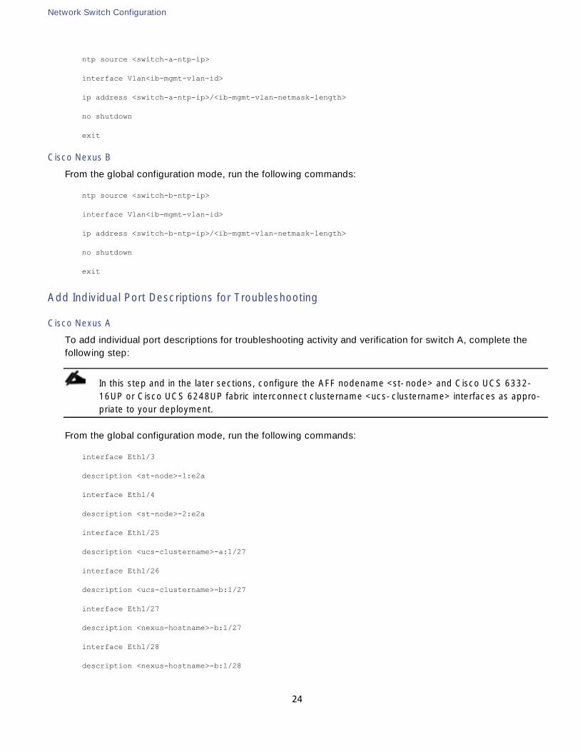
Add Individual Port Descriptions for Troubleshooting
Cisco Nexus A
To add individual port descriptions for troubleshooting activity and verification for switch A, complete the
following step:
In this step and in the later sections, configure the AFF nodename <st-node> and Cisco UCS 6332-
16UP or Cisco UCS 6248UP fabric interconnect clustername <ucs-clustername> interfaces as appro-
priate to your deployment.
From the global configuration mode, run the following commands:
interface Eth1/3
description <st-node>-1:e2a
interface Eth1/4
description <st-node>-2:e2a
interface Eth1/25
description <ucs-clustername>-a:1/27
interface Eth1/26
description <ucs-clustername>-b:1/27
interface Eth1/27
description <nexus-hostname>-b:1/27
interface Eth1/28
description <nexus-hostname>-b:1/28

Network Switch Configuration
25
exit
Cisco Nexus B
To add individual port descriptions for troubleshooting activity and verification for switch B, complete the
following step:
From the global configuration mode, run the following commands:
interface Eth1/3
description <st-node>-1:e2e
interface Eth1/4
description <st-node>-2:e2e
interface Eth1/25
description <ucs-clustername>-a:1/28
interface Eth1/26
description <ucs-clustername>-b:1/28
interface Eth1/27
description <nexus-hostname>-a:1/27
interface Eth1/28
description <nexus-hostname>-a:1/28
exit
Create Port Channels
Cisco Nexus A and Cisco Nexus B
To create the necessary port channels between devices, complete the following step on both switches:
From the global configuration mode, run the following commands:
interface Po10
description vPC peer-link
interface Eth1/27-28
channel-group 10 mode active
no shutdown
interface Po13
description <st-node>-1
interface Eth1/3
channel-group 13 mode active

Network Switch Configuration
26
no shutdown
interface Po14
description <st-node>-2
interface Eth1/4
channel-group 14 mode active
no shutdown
interface Po125
description <ucs-clustername>-a
interface Eth1/25
channel-group 125 mode active
no shutdown
interface Po126
description <ucs-clustername>-b
interface Eth1/26
channel-group 126 mode active
no shutdown
exit
copy run start
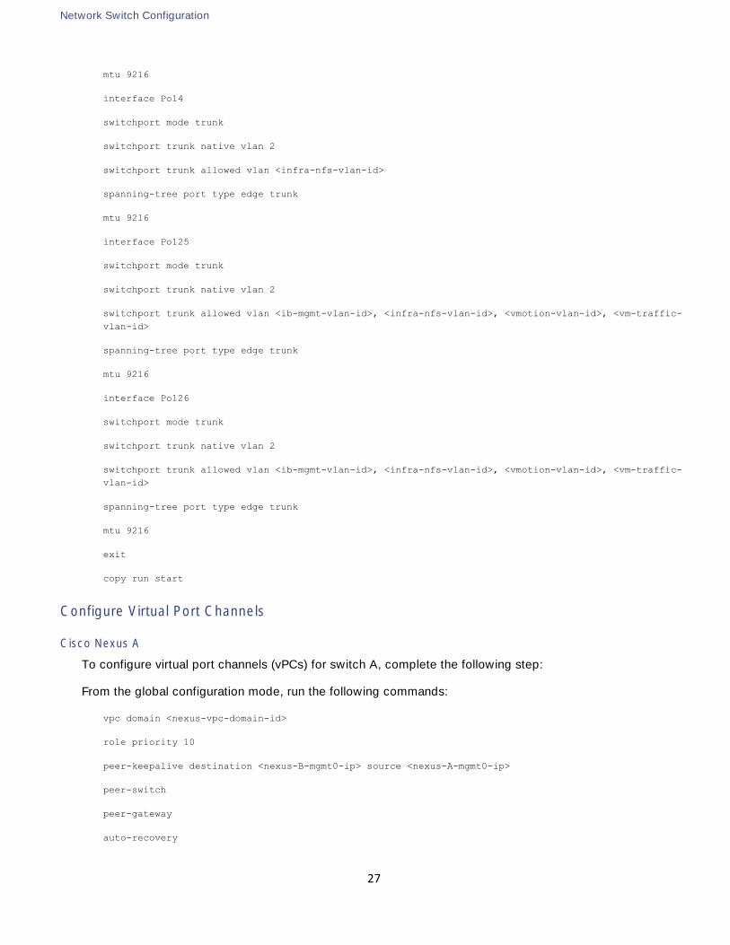
Configure Port Channel Parameters
Cisco Nexus A and Cisco Nexus B
To configure port channel parameters, complete the following step on both switches:
From the global configuration mode, run the following commands:
interface Po10
switchport mode trunk
switchport trunk native vlan 2
switchport trunk allowed vlan <ib-mgmt-vlan-id>, <infra-nfs-vlan-id>, <vmotion-vlan-id>, <vm-traffic-
vlan-id>
spanning-tree port type network
interface Po13
switchport mode trunk
switchport trunk native vlan 2
switchport trunk allowed vlan <infra-nfs-vlan-id>
spanning-tree port type edge trunk
Network Switch Configuration
27
mtu 9216
interface Po14
switchport mode trunk
switchport trunk native vlan 2
switchport trunk allowed vlan <infra-nfs-vlan-id>
spanning-tree port type edge trunk
mtu 9216
interface Po125
switchport mode trunk
switchport trunk native vlan 2
switchport trunk allowed vlan <ib-mgmt-vlan-id>, <infra-nfs-vlan-id>, <vmotion-vlan-id>, <vm-traffic-
vlan-id>
spanning-tree port type edge trunk
mtu 9216
interface Po126
switchport mode trunk
switchport trunk native vlan 2
switchport trunk allowed vlan <ib-mgmt-vlan-id>, <infra-nfs-vlan-id>, <vmotion-vlan-id>, <vm-traffic-
vlan-id>
spanning-tree port type edge trunk
mtu 9216
exit
copy run start
Configure Virtual Port Channels
Cisco Nexus A
To configure virtual port channels (vPCs) for switch A, complete the following step:
From the global configuration mode, run the following commands:
vpc domain <nexus-vpc-domain-id>
role priority 10
peer-keepalive destination <nexus-B-mgmt0-ip> source <nexus-A-mgmt0-ip>
peer-switch
peer-gateway
auto-recovery

Network Switch Configuration
28
delay restore 150
interface Po10
vpc peer-link
interface Po13
vpc 13
interface Po14
vpc 14
interface Po125
vpc 125
interface Po126
vpc 126
exit
copy run start
Cisco Nexus B
To configure vPCs for switch B, complete the following step:
From the global configuration mode, run the following commands:
vpc domain <nexus-vpc-domain-id>
role priority 20
peer-keepalive destination <nexus-A-mgmt0-ip> source <nexus-B-mgmt0-ip>
peer-switch
peer-gateway
auto-recovery
delay restore 150
interface Po10
vpc peer-link
interface Po13
vpc 13
interface Po14
vpc 14
interface Po125
vpc 125
interface Po126
vpc 126

Network Switch Configuration
29
exit
copy run start
Uplink into Existing Network Infrastructure
Depending on the available network infrastructure, several methods and features can be used to uplink the
FlexPod environment. If an existing Cisco Nexus environment is present, we recommend using vPCs to
uplink the Cisco Nexus switches included in the FlexPod environment into the infrastructure. The previously
described procedures can be used to create an uplink vPC to the existing environment. Make sure to run
copy run start to save the configuration on each switch after the configuration is completed.

Storage Configuration
30
Storage Configuration
NetApp All Flash FAS A300 Controllers
See the following section (NetApp Hardware Universe) for planning the physical location of the storage
systems:
Site Preparation
System Connectivity Requirements
Circuit Breaker, Power Outlet Balancing, System Cabinet Power Cord Plugs, and Console Pinout
Requirements
AFF Series Systems
NetApp Hardware Universe
The NetApp Hardware Universe (HWU) application provides supported hardware and software components
for any specific ONTAP version. It provides configuration information for all the NetApp storage appliances
currently supported by ONTAP software. It also provides a table of component compatibilities.
Confirm that the hardware and software components that you would like to use are supported with the
version of ONTAP that you plan to install by using the HWU application at the NetApp Support site.
1. Access the HWU application to view the System Configuration guides. Click the Controllers tab to
view the compatibility between different version of the ONTAP software and the NetApp storage ap-
pliances with your desired specifications.
2. Alternatively, to compare components by storage appliance, click Compare Storage Systems.
Controllers
Follow the physical installation procedures for the controllers found in the AFF A300 Series product
documentation at the NetApp Support site.
Disk Shelves
NetApp storage systems support a wide variety of disk shelves and disk drives. The complete list of disk
shelves that are supported by the AFF A300 is available at the NetApp Support site.
When using SAS disk shelves with NetApp storage controllers, refer to the SAS Disk Shelves Universal SAS
and ACP Cabling Guide for proper cabling guidelines.

Storage Configuration
31
NetApp ONTAP 9.1
Complete Configuration Worksheet
Before running the setup script, complete the cluster setup worksheet from the ONTAP 9.1 Software Setup
Guide. You must have access to the NetApp Support site to open the cluster setup worksheet.
Configure ONTAP Nodes
Before running the setup script, review the configuration worksheets in the ONTAP 9.1 Software Setup
Guide to learn about configuring ONTAP. Table 4 lists the information needed to configure two ONTAP
nodes. Customize the cluster detail values with the information applicable to your deployment.
Table 4 ONTAP Software Installation Prerequisites
Cluster Detail Cluster Detail Value
Cluster node 01 IP address <node01-mgmt-ip>
Cluster node 01 netmask <node01-mgmt-mask>
Cluster node 01 gateway <node01-mgmt-gateway>
Cluster node 02 IP address <node02-mgmt-ip>
Cluster node 02 netmask <node02-mgmt-mask>
Cluster node 02 gateway <node02-mgmt-gateway>
Data ONTAP 9.1 URL <url-boot-software>
Configure Node 01
To configure node 01, complete the following steps:
1. Connect to the storage system console port. You should see a Loader-A prompt. However, if the
storage system is in a reboot loop, press Ctrl-C to exit the autoboot loop when the following mes-
sage displays:
Starting AUTOBOOT press Ctrl-C to abort…
2. Allow the system to boot up.
autoboot
3. Press Ctrl-C when prompted.
If ONTAP 9.1 is not the version of software being booted, continue with the following steps to install
new software. If ONTAP 9.1 is the version being booted, select option 8 and y to reboot the node.
Then continue with step 14.

Storage Configuration
32
4. To install new software, select option 7.
5. Enter y to perform an upgrade.
6. Select e0M for the network port you want to use for the download.
7. Enter y to reboot now.
8. Enter the IP address, netmask, and default gateway for e0M.
<node01-mgmt-ip> <node01-mgmt-mask> <node01-mgmt-gateway>
9. Enter the URL where the software can be found.
This web server must be pingable.
<url-boot-software>
10. Press Enter for the user name, indicating no user name.
11. Enter y to set the newly installed software as the default to be used for subsequent reboots.
12. Enter y to reboot the node.
When installing new software, the system might perform firmware upgrades to the BIOS and adapter
cards, causing reboots and possible stops at the Loader-A prompt. If these actions occur, the system
might deviate from this procedure.
13. Press Ctrl-C when the following message displays:
Press Ctrl-C for Boot Menu
14. Select option 4 for Clean Configuration and Initialize All Disks.
15. Enter y to zero disks, reset config, and install a new file system.
16. Enter y to erase all the data on the disks.
The initialization and creation of the root aggregate can take 90 minutes or more to complete, depend-
ing on the number and type of disks attached. When initialization is complete, the storage system re-
boots. Note that SSDs take considerably less time to initialize. You can continue with the node 02 con-
figuration while the disks for node 01 are zeroing.
Configure Node 02
To configure node 02, complete the following steps:
1. Connect to the storage system console port. You should see a Loader-A prompt. However, if the
storage system is in a reboot loop, press Ctrl-C to exit the autoboot loop when the following mes-
sage displays:

Storage Configuration
33
Starting AUTOBOOT press Ctrl-C to abort…
2. Allow the system to boot up.
autoboot
3. Press Ctrl-C when prompted.
If ONTAP 9.1 is not the version of software being booted, continue with the following steps to install
new software. If ONTAP 9.1 is the version being booted, select option 8 and y to reboot the node.
Then continue with step 14.
4. To install new software, select option 7.
5. Enter y to perform an upgrade.
6. Select e0M for the network port you want to use for the download.
7. Enter y to reboot now.
8. Enter the IP address, netmask, and default gateway for e0M.
<node02-mgmt-ip> <node02-mgmt-mask> <node02-mgmt-gateway>
9. Enter the URL where the software can be found.
This web server must be pingable.
<url-boot-software>
10. Press Enter for the user name, indicating no user name.
11. Enter y to set the newly installed software as the default to be used for subsequent reboots.
12. Enter y to reboot the node.
When installing new software, the system might perform firmware upgrades to the BIOS and adapter
cards, causing reboots and possible stops at the Loader-A prompt. If these actions occur, the system
might deviate from this procedure.
13. Press Ctrl-C when you see this message:
Press Ctrl-C for Boot Menu
14. Select option 4 for Clean Configuration and Initialize All Disks.
15. Enter y to zero disks, reset config, and install a new file system.
16. Enter y to erase all the data on the disks.
Storage Configuration
34
The initialization and creation of the root aggregate can take 90 minutes or more to complete, depend-
ing on the number and type of disks attached. When initialization is complete, the storage system re-
boots. Note that SSDs take considerably less time to initialize.
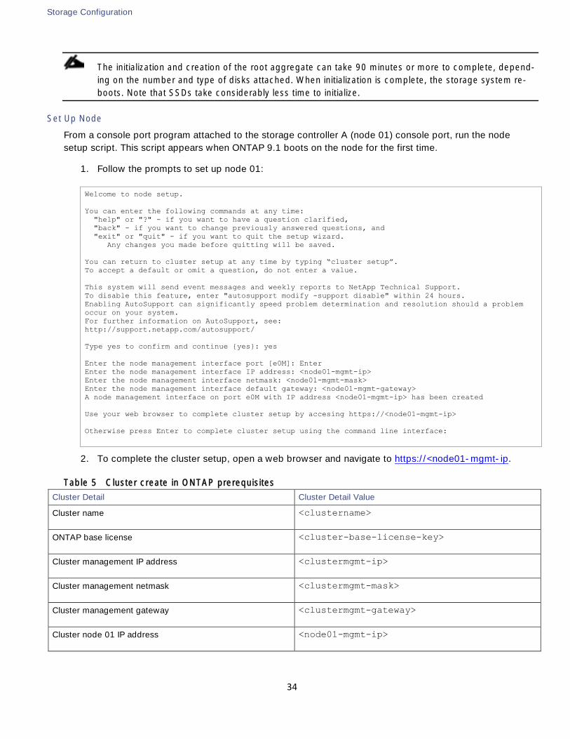
Set Up Node
From a console port program attached to the storage controller A (node 01) console port, run the node
setup script. This script appears when ONTAP 9.1 boots on the node for the first time.
1. Follow the prompts to set up node 01:
Welcome to node setup.
You can enter the following commands at any time:
"help" or "?" - if you want to have a question clarified,
"back" - if you want to change previously answered questions, and
"exit" or "quit" - if you want to quit the setup wizard.
Any changes you made before quitting will be saved.
You can return to cluster setup at any time by typing “cluster setup”.
To accept a default or omit a question, do not enter a value.
This system will send event messages and weekly reports to NetApp Technical Support.
To disable this feature, enter "autosupport modify -support disable" within 24 hours.
Enabling AutoSupport can significantly speed problem determination and resolution should a problem
occur on your system.
For further information on AutoSupport, see:
http://support.netapp.com/autosupport/
Type yes to confirm and continue {yes}: yes
Enter the node management interface port [e0M]: Enter
Enter the node management interface IP address: <node01-mgmt-ip>
Enter the node management interface netmask: <node01-mgmt-mask>
Enter the node management interface default gateway: <node01-mgmt-gateway>
A node management interface on port e0M with IP address <node01-mgmt-ip> has been created
Use your web browser to complete cluster setup by accesing https://<node01-mgmt-ip>
Otherwise press Enter to complete cluster setup using the command line interface:
2. To complete the cluster setup, open a web browser and navigate to https://<node01-mgmt-ip.
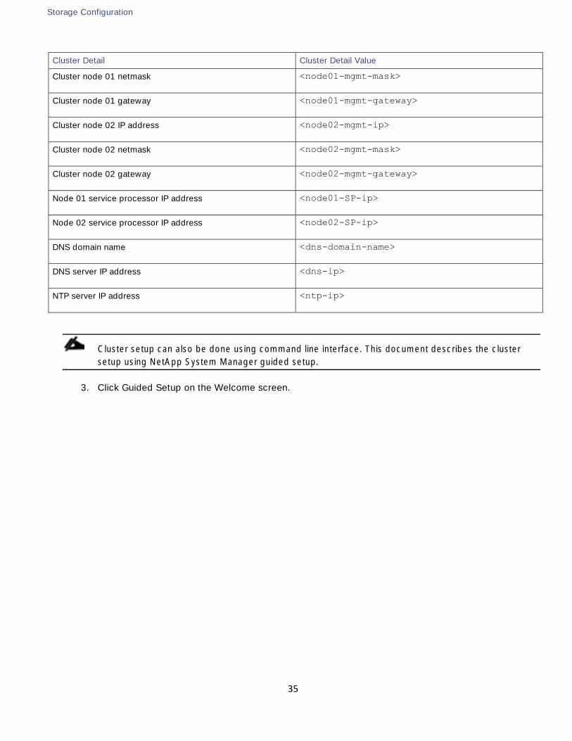
Table 5 Cluster create in ONTAP prerequisites
Cluster Detail Cluster Detail Value
Cluster name <clustername>
ONTAP base license <cluster-base-license-key>
Cluster management IP address <clustermgmt-ip>
Cluster management netmask <clustermgmt-mask>
Cluster management gateway <clustermgmt-gateway>
Cluster node 01 IP address <node01-mgmt-ip>
Storage Configuration
35
Cluster Detail Cluster Detail Value
Cluster node 01 netmask <node01-mgmt-mask>
Cluster node 01 gateway <node01-mgmt-gateway>
Cluster node 02 IP address <node02-mgmt-ip>
Cluster node 02 netmask <node02-mgmt-mask>
Cluster node 02 gateway <node02-mgmt-gateway>
Node 01 service processor IP address <node01-SP-ip>
Node 02 service processor IP address <node02-SP-ip>
DNS domain name <dns-domain-name>
DNS server IP address <dns-ip>
NTP server IP address <ntp-ip>
Cluster setup can also be done using command line interface. This document describes the cluster
setup using NetApp System Manager guided setup.
3. Click Guided Setup on the Welcome screen.

Storage Configuration
36
4. In the Cluster screen, do the following:
Enter the cluster and node names.
Select the cluster configuration.
Enter and confirm the password.
(Optional) Enter the cluster base and feature licenses.

Storage Configuration
37
The nodes are discovered automatically; if they are not, click the Refresh link. By default, the cluster
interfaces will be created on all the new factory shipping storage controllers.
If all the nodes are not discovered, then configure the cluster using the command line.

Storage Configuration
38
Cluster license and feature licenses can also be installed after completing the cluster creation.
5. Click Submit.
6. In the network page, complete the following sections:
Cluster Management
Enter the IP address, netmask, gateway, and port details.
Node Management
Enter the node management IP addresses and port details for all the nodes.
Service Processor Management
Enter the IP addresses for all the nodes.
DNS Details
Enter the DNS domain names and server address.
NTP Details
Enter the primary and alternate NTP server.
7. Click Submit.
8. In the Support page, configure the AutoSupport and Event Notifications sections.

Storage Configuration
39
9. Click Submit.
10. In the Summary page, review the configuration details if needed.

Storage Configuration
40
The node management interface can be on the same subnet as the cluster management interface, or it
can be on a different subnet. In this document, we assume that it is on the same subnet.
Login to the Cluster
To log in to the cluster, complete the following steps:
1. Open an SSH connection to either the cluster IP or host name.
2. Log in to the admin user with the password you provided earlier.
Zero All Spare Disks
To zero all spare disks in the cluster, run the following command:
disk zerospares
Advanced Data Partitioning creates a root partition and two data partitions on each SSD drive in an All
Flash FAS configuration. Disk autoassign should have assigned one data partition to each node in an
HA pair. If a different disk assignment is required, disk autoassignment must be disabled on both
nodes in the HA pair by running the disk option modify command. Spare partitions can then be
moved from one node to another by running the disk removeowner and disk assign commands.
Set Onboard Unified Target Adapter 2 Port Personality
To set the personality of the onboard unified target adapter 2 (UTA2), complete the following steps:
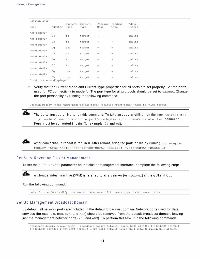
1. Verify the Current Mode and Current Type properties of the ports by running the ucadmin show
command:
Storage Configuration
41
ucadmin show
Current Current Pending Pending Admin
Node Adapter Mode Type Mode Type Status
------------ ------- ------- --------- ------- --------- -----------
<st-node01>
0e fc target - - online
<st-node01>
0f fc target - - online
<st-node01>
0g cna target - - online
<st-node01>
0h cna target - - online
<st-node02>
0e fc target - - online
<st-node02>
0f fc target - - online
<st-node02>
0g cna target - - online
<st-node02>
0h cna target - - online
8 entries were displayed.
2. Verify that the Current Mode and Current Type properties for all ports are set properly. Set the ports
used for FC connectivity to mode fc. The port type for all protocols should be set to target. Change
the port personality by running the following command:
ucadmin modify -node <home-node-of-the-port> -adapter <port-name> -mode fc -type target
The ports must be offline to run this command. To take an adapter offline, run the fcp adapter mod-
ify –node <home-node-of-the-port> -adapter <port-name> -state down command.
Ports must be converted in pairs (for example, 0e and 0f).
After conversion, a reboot is required. After reboot, bring the ports online by running fcp adapter
modify -node <home-node-of-the-port> -adapter <port-name> -state up.
Set Auto-Revert on Cluster Management
To set the auto-revert parameter on the cluster management interface, complete the following step:
A storage virtual machine (SVM) is referred to as a Vserver (or vserver) in the GUI and CLI.
Run the following command:
network interface modify –vserver <clustername> -lif cluster_mgmt –auto-revert true
Set Up Management Broadcast Domain
By default, all network ports are included in the default broadcast domain. Network ports used for data
services (for example, e0d, e2a, and e2e) should be removed from the default broadcast domain, leaving
just the management network ports (e0c and e0M). To perform this task, run the following commands:
broadcast-domain remove-ports -broadcast-domain Default -ports bb04-affa300-1:e0d,bb04-affa300-
1:e0g,bb04-affa300-1:e0h,bb04-affa300-1:e2a,bb04-affa300-1:e2e,bb04-affa300-2:e0d,bb04-affa300-

Storage Configuration
42
2:e0g,bb04-affa300-2:e0h,bb04-affa300-2:e2a,bb04-affa300-2:e2e
broadcast-domain show
Set Up Service Processor Network Interface
To assign a static IPv4 address to the service processor on each node, run the following commands:
system service-processor network modify –node <st-node01> -address-family IPv4 –enable true –dhcp
none –ip-address <node01-sp-ip> -netmask <node01-sp-mask> -gateway <node01-sp-gateway>
system service-processor network modify –node <st-node02> -address-family IPv4 –enable true –dhcp
none –ip-address <node02-sp-ip> -netmask <node02-sp-mask> -gateway <node02-sp-gateway>
The service processor IP addresses should be in the same subnet as the node management IP ad-
dresses.
Create Aggregates
An aggregate containing the root volume is created during the ONTAP setup process. To create additional
aggregates, determine the aggregate name, the node on which to create it, and the number of disks it
should contain.
To create new aggregates, complete the following steps:
1. Run the following commands:
aggr create -aggregate aggr1_node01 -node <st-node01> -diskcount <num-disks>
aggr create -aggregate aggr1_node02 -node <st-node02> -diskcount <num-disks>
You should have the minimum number of hot spare disks for hot spare disk partitions recommended
for your aggregate.
For all flash aggregates, you should have a minimum of one hot spare disk or disk partition. For non-
flash homogenous aggregates, you should have a minimum of two hot spare disks or disk partitions.
For Flash Pool aggregates, you should have a minimum of two hot spare disks or disk partitions for
each disk type.
Start with five disks initially; you can add disks to an aggregate when additional storage is required. In
an AFF configuration with a small number of SSDs, you might want to create an aggregate with all but
one remaining disk (spare) assigned to the controller.
The aggregate cannot be created until disk zeroing completes. Run the aggr show command to dis-
play aggregate creation status. Do not proceed until both aggr1_node1 and aggr1_node2 are online.

Storage Configuration
43
aggr show
aggr rename –aggregate aggr0 –newname <node01-rootaggrname>
Verify Storage Failover
To confirm that storage failover is enabled, run the following commands for a failover pair:
1. Verify the status of the storage failover.
storage failover show
Both <st-node01> and <st-node02> must be capable of performing a takeover. Continue with step
3 if the nodes are capable of performing a takeover.
2. Enable failover on one of the two nodes.
storage failover modify -node <st-node01> -enabled true
Enabling failover on one node enables it for both nodes.
3. Verify the HA status for a two-node cluster.
This step is not applicable for clusters with more than two nodes.
cluster ha show
4. Continue with step 6 if high availability is configured.
5. Only enable HA mode for two-node clusters. Do not run this command for clusters with more than
two nodes because it causes problems with failover.
cluster ha modify -configured true
Do you want to continue? {y|n}: y
6. Verify that hardware assist is correctly configured and, if needed, modify the partner IP address.
storage failover hwassist show
storage failover modify –hwassist-partner-ip <node02-mgmt-ip> -node <st-node01>
storage failover modify –hwassist-partner-ip <node01-mgmt-ip> -node <st-node02>
Disable Flow Control on 10GbE and 40GbE ports
NetApp recommends disabling flow control on all the 10GbE and UTA2 ports that are connected to external
devices. To disable flow control, complete the following steps:
1. Run the following commands to configure node 01:
network port modify -node <st-node01> -port e0a,e0b,e0e,e0f,e0g,e0h,e2a,e2e -flowcontrol-admin none
Warning: Changing the network port settings will cause a several second interruption in carrier.
Do you want to continue? {y|n}: y
2. Run the following commands to configure node 02:
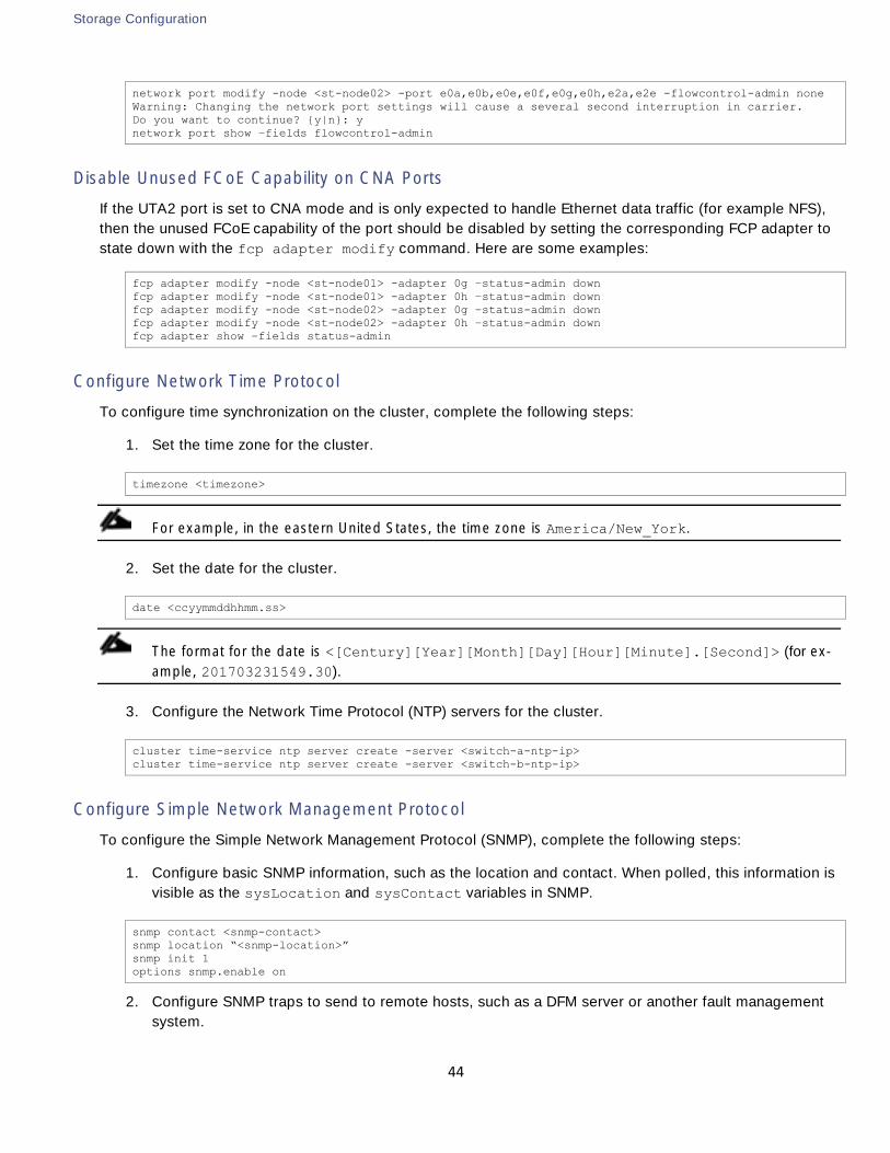
Storage Configuration
44
network port modify -node <st-node02> -port e0a,e0b,e0e,e0f,e0g,e0h,e2a,e2e -flowcontrol-admin none
Warning: Changing the network port settings will cause a several second interruption in carrier.
Do you want to continue? {y|n}: y
network port show –fields flowcontrol-admin
Disable Unused FCoE Capability on CNA Ports
If the UTA2 port is set to CNA mode and is only expected to handle Ethernet data traffic (for example NFS),
then the unused FCoE capability of the port should be disabled by setting the corresponding FCP adapter to
state down with the fcp adapter modify command. Here are some examples:
fcp adapter modify -node <st-node01> -adapter 0g –status-admin down
fcp adapter modify -node <st-node01> -adapter 0h –status-admin down
fcp adapter modify -node <st-node02> -adapter 0g –status-admin down
fcp adapter modify -node <st-node02> -adapter 0h –status-admin down
fcp adapter show –fields status-admin
Configure Network Time Protocol
To configure time synchronization on the cluster, complete the following steps:
1. Set the time zone for the cluster.
timezone <timezone>
For example, in the eastern United States, the time zone is America/New_York.
2. Set the date for the cluster.
date <ccyymmddhhmm.ss>
The format for the date is <[Century][Year][Month][Day][Hour][Minute].[Second]> (for ex-
ample, 201703231549.30).
3. Configure the Network Time Protocol (NTP) servers for the cluster.
cluster time-service ntp server create -server <switch-a-ntp-ip>
cluster time-service ntp server create -server <switch-b-ntp-ip>
Configure Simple Network Management Protocol
To configure the Simple Network Management Protocol (SNMP), complete the following steps:
1. Configure basic SNMP information, such as the location and contact. When polled, this information is
visible as the sysLocation and sysContact variables in SNMP.
snmp contact <snmp-contact>
snmp location “<snmp-location>”
snmp init 1
options snmp.enable on
2. Configure SNMP traps to send to remote hosts, such as a DFM server or another fault management
system.

Storage Configuration
45
snmp traphost add <oncommand-um-server-fqdn>
Configure SNMPv1 Access
To configure SNMPv1 access, set the shared, secret plain-text password (called a community):
snmp community add ro <snmp-community>
Configure AutoSupport
NetApp AutoSupport® sends support summary information to NetApp through HTTPS. To configure
AutoSupport, run the following command:
system node autosupport modify -node * -state enable –mail-hosts <mailhost> -transport https -support
enable -noteto <storage-admin-email>
Enable Cisco Discovery Protocol
To enable the Cisco Discovery Protocol (CDP) on the NetApp storage controllers, run the following
command to enable CDP on ONTAP:
node run -node * options cdpd.enable on
To be effective, CDP must also be enabled on directly connected networking equipment such as
switches and routers.
Create Jumbo Frame MTU Broadcast Domains in ONTAP
To create a data broadcast domain with an MTU of 9000, run the following commands to create a broadcast
domain for NFS on ONTAP:
broadcast-domain create -broadcast-domain Infra_NFS -mtu 9000
Create Interface Groups
To create the LACP interface groups for the 10GbE data interfaces, run the following commands:
ifgrp create -node <st-node01> -ifgrp a0a -distr-func port -mode multimode_lacp
ifgrp add-port -node <st-node01> -ifgrp a0a -port e2a
ifgrp add-port -node <st-node01> -ifgrp a0a -port e2e
ifgrp create -node <st-node02> -ifgrp a0a -distr-func port -mode multimode_lacp
ifgrp add-port -node <st-node02> -ifgrp a0a -port e2a
ifgrp add-port -node <st-node02> -ifgrp a0a -port e2e
ifgrp show
Create VLANs
To create VLANs, create NFS VLAN ports and add them to the NFS broadcast domain:
network port modify –node <st-node01> -port a0a –mtu 9000
network port modify –node <st-node02> -port a0a –mtu 9000
network port vlan create –node <st-node01> -vlan-name a0a-<infra-nfs-vlan-id>
network port vlan create –node <st-node02> -vlan-name a0a-<infra-nfs-vlan-id>

Storage Configuration
46
broadcast-domain add-ports -broadcast-domain Infra_NFS -ports <st-node01>:a0a-<infra-nfs-vlan-id>,
<st-node02>:a0a-<infra-nfs-vlan-id>
Create Storage Virtual Machine
To create an infrastructure SVM, complete the following steps:
1. Run the vserver create command.
vserver create –vserver Infra-SVM –rootvolume rootvol –aggregate aggr1_node01 –rootvolume-security-
style unix
2. Remove the unused data protocols from the SVM - CIFS, iSCSI, and NDMP.
vserver remove-protocols –vserver Infra-SVM -protocols iscsi,cifs,ndmp
3. Add the two data aggregates to the Infra-SVM aggregate list for the NetApp VSC.
vserver modify –vserver Infra-SVM –aggr-list aggr1_node01,aggr1_node02
4. Enable and run the NFS protocol in the Infra-SVM.
nfs create -vserver Infra-SVM -udp disabled
If NFS license is not installed during the cluster configuration, make sure install the license for staring
the NFS service.
5. Turn on the SVM vstorage parameter for the NetApp NFS VAAI plug-in.
vserver nfs modify –vserver Infra-SVM –vstorage enabled
vserver nfs show
Create Load-Sharing Mirrors of SVM Root Volume
To create a load-sharing mirror of an SVM root volume, complete the following steps:
1. Create a volume to be the load-sharing mirror of the infrastructure SVM root volume on each node.
volume create –vserver Infra-SVM –volume rootvol_m01 –aggregate aggr1_node01 –size 1GB –type DP
volume create –vserver Infra-SVM –volume rootvol_m02 –aggregate aggr1_node02 –size 1GB –type DP
2. Create a job schedule to update the root volume mirror relationships every 15 minutes.
job schedule interval create -name 15min -minutes 15
3. Create the mirroring relationships.
snapmirror create –source-path Infra-SVM:rootvol –destination-path Infra-SVM:rootvol_m01 –type LS -
schedule 15min
snapmirror create –source-path Infra-SVM:rootvol –destination-path Infra-SVM:rootvol_m02 –type LS -
schedule 15min
4. Initialize the mirroring relationship.

Storage Configuration
47
snapmirror initialize-ls-set –source-path Infra-SVM:rootvol
snapmirror show
Create Block Protocol (FC) Service
Run the following command to create the FCP service on each SVM. This command also starts the FCP
service and sets the WWN for the SVM.
fcp create -vserver Infra-SVM
fcp show
If FC license is not installed during the cluster configuration, make sure install the license for creating
FC service
Configure HTTPS Access
To configure secure access to the storage controller, complete the following steps:
1. Increase the privilege level to access the certificate commands.
set -privilege diag
Do you want to continue? {y|n}: y
2. Generally, a self-signed certificate is already in place. Verify the certificate and obtain parameters
(for example, <serial-number>) by running the following command:
security certificate show
For each SVM shown, the certificate common name should match the DNS FQDN of the SVM. Delete the two
default certificates and replace them with either self-signed certificates or certificates from a certificate
authority (CA). To delete the default certificates, run the following commands:
security certificate delete -vserver Infra-SVM -common-name Infra-SVM -ca Infra-SVM -type server -
serial <serial-number>
Deleting expired certificates before creating new certificates is a best practice. Run the security
certificate delete command to delete the expired certificates. In the following command, use
TAB completion to select and delete each default certificate.
3. To generate and install self-signed certificates, run the following commands as one-time commands.
Generate a server certificate for the Infra-SVM and the cluster SVM. Use TAB completion to aid in
the completion of these commands.
security certificate create -common-name <cert-common-name> -type server -size 2048 -country <cert-
country> -state <cert-state> -locality <cert-locality> -organization <cert-org> -unit <cert-unit> -
email-addr <cert-email> -expire-days <cert-days> -protocol SSL -hash-function SHA256 -vserver Infra-
SVM
4. To obtain the values for the parameters required in step 5 (<cert-ca> and <cert-serial>), run the se-
curity certificate show command.
5. Enable each certificate that was just created by using the server-enabled true and client-enabled
false parameters. Use TAB completion to aid in the completion of these commands.

Storage Configuration
48
security ssl modify -vserver <clustername> -server-enabled true -client-enabled false -ca <cert-ca> -
serial <cert-serial> -common-name <cert-common-name>
6. Disable HTTP cluster management access.
system services firewall policy delete -policy mgmt -service http –vserver <clustername>
It is normal for some of these commands to return an error message stating that the entry does not
exist.
7. Change back to the normal admin privilege level and set up the system to allow SVM logs to be
available by web.
set –privilege admin
vserver services web modify –name spi|ontapi|compat –vserver * -enabled true
Configure NFSv3
To configure NFSv3 on the SVM, complete the following steps:
1. Create a new rule for the infrastructure NFS subnet in the default export policy.
vserver export-policy rule create –vserver Infra-SVM -policyname default –ruleindex 1 –protocol nfs -
clientmatch <infra-nfs-subnet-cidr> -rorule sys –rwrule sys -superuser sys –allow-suid false
2. Assign the FlexPod export policy to the infrastructure SVM root volume.
volume modify –vserver Infra-SVM –volume rootvol –policy default
Create FlexVol Volumes
The following information is required to create a NetApp FlexVol® volume:
The volume name
The volume size
The aggregate on which the volume exists
To create a FlexVol volume, run the following commands:
volume create -vserver Infra-SVM -volume infra_datastore_1 -aggregate aggr1_node01 -size 500GB -state
online -policy default -junction-path /infra_datastore_1 -space-guarantee none -percent-snapshot-
space 0
volume create -vserver Infra-SVM -volume infra_datastore_2 -aggregate aggr1_node02 -size 500GB -state
online -policy default -junction-path /infra_datastore_2 -space-guarantee none -percent-snapshot-
space 0
volume create -vserver Infra-SVM -volume esxi_boot -aggregate aggr1_node01 -size 100GB -state online
-policy default -space-guarantee none -percent-snapshot-space 0
snapmirror update-ls-set -source-path Infra-SVM:rootvol
Create Boot LUNs
To create two boot LUNs, run the following commands:

Storage Configuration
49
lun create -vserver Infra-SVM -volume esxi_boot -lun VM-Host-Infra-01 -size 15GB -ostype vmware -
space-reserve disabled
lun create -vserver Infra-SVM -volume esxi_boot -lun VM-Host-Infra-02 -size 15GB -ostype vmware -
space-reserve disabled
Schedule Deduplication
On NetApp All Flash FAS systems, deduplication is enabled by default. To schedule deduplication, complete
the following step:
1. After the volumes are created, assign a once-a-day deduplication schedule to esxi_boot, in-
fra_datastore_1 and infra_datastore_2:
efficiency modify –vserver Infra-SVM –volume esxi_boot –schedule sun-sat@0
efficiency modify –vserver Infra-SVM –volume infra_datastore_1 –schedule sun-sat@0 efficiency modify –vserver Infra-SVM –volume infra_datastore_2 –schedule sun-sat@0
Create FC LIFs
Run the following commands to create four FC LIFs (two on each node):
network interface create -vserver Infra-SVM -lif fcp_lif01a -role data -data-protocol fcp -home-node
<st-node01> -home-port 0e –status-admin up
network interface create -vserver Infra-SVM -lif fcp_lif01b -role data -data-protocol fcp -home-node
<st-node01> -home-port 0f –status-admin up
network interface create -vserver Infra-SVM -lif fcp_lif02a -role data -data-protocol fcp -home-node
<st-node02> -home-port 0e –status-admin up
network interface create -vserver Infra-SVM -lif fcp_lif02b -role data -data-protocol fcp -home-node
<st-node02> -home-port 0f –status-admin up
network interface show
Create NFS LIF
To create an NFS LIF, run the following commands:
network interface create -vserver Infra-SVM -lif nfs_lif01 -role data -data-protocol nfs -home-node
<st-node01> -home-port a0a-<infra-nfs-vlan-id> –address <node01-nfs_lif01-ip> -netmask <node01-
nfs_lif01-mask> -status-admin up –failover-policy broadcast-domain-wide –firewall-policy data –auto-
revert true
network interface create -vserver Infra-SVM -lif nfs_lif02 -role data -data-protocol nfs -home-node
<st-node02> -home-port a0a-<infra-nfs-vlan-id> –address <node02-nfs_lif02-ip> -netmask <node02-
nfs_lif02-mask>> -status-admin up –failover-policy broadcast-domain-wide –firewall-policy data –auto-
revert true
network interface show
Add Infrastructure SVM Administrator
To add the infrastructure SVM administrator and SVM administration LIF in the out-of-band management
network, complete the following steps:
1. Run the following commands:

Storage Configuration
50
network interface create –vserver Infra-SVM –lif svm-mgmt –role data –data-protocol none –home-node
<st-node02> -home-port e0c –address <svm-mgmt-ip> -netmask <svm-mgmt-mask> -status-admin up –
failover-policy broadcast-domain-wide –firewall-policy mgmt –auto-revert true
The SVM management IP in this step should be in the same subnet as the storage cluster management
IP.
2. Create a default route to allow the SVM management interface to reach the outside world.
network route create –vserver Infra-SVM -destination 0.0.0.0/0 –gateway <svm-mgmt-gateway>
network route show
3. Set a password for the SVM vsadmin user and unlock the user.
security login password –username vsadmin –vserver Infra-SVM
Enter a new password: <password>
Enter it again: <password>
security login unlock –username vsadmin –vserver Infra-SVM
A cluster serves data through at least one and possibly several SVMs. We have just gone through cre-
ating a single SVM. If you would like to configure your environment with multiple SVMs, this is a good
time to create additional SVMs.

Server Configuration
51
Server Configuration
Cisco UCS Base Configuration
This FlexPod deployment will show configuration steps for the Cisco UCS 6332-16UP Fabric Interconnects
(FI) in a design that will support Fibre Channel to the NetApp AFF through the Cisco Nexus.
Perform Initial Setup of Cisco UCS 6332-16UP Fabric Interconnects for FlexPod Environments
This section provides detailed procedures for configuring the Cisco Unified Computing System (Cisco UCS)
for use in a FlexPod environment. The steps are necessary to provision the Cisco UCS B-Series and C-
Series servers and should be followed precisely to avoid improper configuration.
Cisco UCS Fabric Interconnect A
To configure the Cisco UCS for use in a FlexPod environment, complete the following steps:
1. Connect to the console port on the first Cisco UCS fabric interconnect.
Enter the configuration method: gui
Physical switch Mgmt0 IP address: <ucsa-mgmt-ip>
Physical switch Mgmt0 IPv4 netmask: <ucsa-mgmt-mask>
IPv4 address of the default gateway: <ucsa-mgmt-gateway>
2. Using a supported web browser, connect to https://<ucsa-mgmt-ip>, accept the security prompts,
and
3. Select Initial Setup and click Submit.
4. Select Enable clustering, Fabric A, and IPv4.
5. Fill in the Virtual IP Address with the UCS cluster IP.
6. Completely fill in the System setup section. For system name, use the overall UCS system name. For
the Mgmt IP Address, use <ucsa-mgmt-ip>.

Server Configuration
52
7. Click Submit.
Cisco UCS Fabric Interconnect B
To configure the Cisco UCS for use in a FlexPod environment, complete the following steps:
1. Connect to the console port on the second Cisco UCS fabric interconnect.
Enter the configuration method: gui
Physical switch Mgmt0 IP address: <ucsb-mgmt-ip>
Physical switch Mgmt0 IPv4 netmask: <ucsb-mgmt-mask>
IPv4 address of the default gateway: <ucsb-mgmt-gateway>

Server Configuration
53
2. Using a supported web browser, connect to https://<ucsb-mgmt-ip>, accept the security prompts,
3. Under System setup, enter the Admin Password entered above and click Submit.
4. Enter <ucsb-mgmt-ip> for the Mgmt IP Address and click Submit.
Cisco UCS Setup
Log into Cisco UCS Manager
To log into the Cisco Unified Computing System (UCS) environment, complete the following steps:
1. Open a web browser and navigate to the Cisco UCS fabric interconnect cluster address.
You may need to wait at least 5 minutes after configuring the second fabric interconnect for UCS Man-
ager to come up.
2. Click the Launch UCS Manager link under HTML to launch Cisco UCS Manager.
3. If prompted to accept security certificates, accept as necessary.
4. When prompted, enter admin as the user name and enter the administrative password.
5. Click Login to log in to Cisco UCS Manager.
Upgrade Cisco UCS Manager Software to Version 3.1(2f)
This document assumes the use of Cisco UCS 3.1(2f). To upgrade the Cisco UCS Manager software and the
Cisco UCS Fabric Interconnect software to version 3.1(2f), refer to Cisco UCS Manager Install and Upgrade
Guides.
Anonymous Reporting
To create anonymous reporting, complete the following step:
1. In the Anonymous Reporting window, select whether to send anonymous data to Cisco for improving
future products. If you select Yes, enter the IP address of your SMTP Server. Click OK.

Server Configuration
54
Configure Cisco UCS Call Home
It is highly recommended by Cisco to configure Call Home in Cisco UCS Manager. Configuring Call Home
will accelerate resolution of support cases. To configure Call Home, complete the following steps:
1. In Cisco UCS Manager, click Admin on the left.
2. Select All > Communication Management > Call Home.
3. Change the State to On.
4. Fill in all the fields according to your Management preferences and click Save Changes and OK to
complete configuring Call Home.
Configure Unified Ports
Fiber Channel port configurations differ slightly between the 6332-16UP and the 6248UP Fabric
Interconnects. Both Fabric Interconnects have a slider mechanism within the Cisco UCS Manager GUI
interface, but the fiber channel port selection options for the 6332-16UP are from the first 16 ports starting
from the first port on the left, and configured in increments of the first 6, 12, or all 16 of the unified
ports. With the 6248UP, the port selection options will start from the right of the 32 fixed ports, or the right
of the 16 ports of the expansion module, going down in contiguous increments of 2.
To enable the fiber channel ports, complete the following steps for the 6332-16UP:
1. In Cisco UCS Manager, click Equipment on the left.
2. Select Equipment > Fabric Interconnects > Fabric Interconnect A (primary).
3. Select Configure Unified Ports.
4. Click Yes on the pop-up window warning that changes to the fixed module will require a reboot of
the fabric interconnect and changes to the expansion module will require a reboot of that module.

Server Configuration
55
5. Within the Configured Fixed Ports pop-up window move the gray slider bar from the left to the right
to select either 6, 12, or 16 ports to be set as FC Uplinks.
6. Click OK, then click Yes, then click OK to continue
7. Select Equipment > Fabric Interconnects > Fabric Interconnect B (primary).
8. Select Configure Unified Ports.
9. Click Yes on the pop-up window warning that changes to the fixed module will require a reboot of
the fabric interconnect and changes to the expansion module will require a reboot of that module.
10. Within the Configured Fixed Ports pop-up window move the gray slider bar from the left to the right
to select either 6, 12, or 16 ports to be set as FC Uplinks.
11. Click OK, then Yes, then OK to continue.
12. Wait for both Fabric Interconnects to reboot.

Server Configuration
56
13. Log back into Cisco UCS Manager.
This process will be similar for the Cisco UCS 6248UP Fabric Interconnect, but will be in increments of
two unified ports that can be converted to FC uplinks, and will slide from the right to the left instead of
the left to the right process used with the Cisco UCS 6332-16UP Fabric Interconnects.
Add Block of IP Addresses for KVM Access
To create a block of IP addresses for in band server Keyboard, Video, Mouse (KVM) access in the Cisco UCS
environment, complete the following steps:
1. In Cisco UCS Manager, click LAN on the left.
2. Expand Pools > root > IP Pools.
3. Right-click IP Pool ext-mgmt and select Create Block of IPv4 Addresses.
4. Enter the starting IP address of the block, number of IP addresses required, and the subnet mask and
gateway information.
5. Click OK to create the block.
6. Click OK in the confirmation message.
Synchronize Cisco UCS to NTP
To synchronize the Cisco UCS environment to the NTP servers in the Nexus switches, complete the
following steps:

Server Configuration
57
1. In Cisco UCS Manager, click Admin on the left.
2. Expand All > Time Zone Management.
3. Select Timezone.
4. In the Properties pane, select the appropriate time zone in the Timezone menu.
5. Click Save Changes, and then click OK.
6. Click Add NTP Server.
7. Enter <switch-a-ntp-ip> and click OK. Click OK on the confirmation.
8. Click Add NTP Server.
9. Enter <switch-b-ntp-ip> and click OK. Click OK on the confirmation.

Server Configuration
58
Edit Chassis Discovery Policy
Setting the discovery policy simplifies the addition of Cisco UCS B-Series chassis and of additional fabric
extenders for further Cisco UCS C-Series connectivity. To modify the chassis discovery policy, complete the
following steps:
1. In Cisco UCS Manager, click Equipment on the left and select Equipment in the second list.
2. In the right pane, click the Policies tab.
3. Under Global Policies, set the Chassis/FEX Discovery Policy to match the minimum number of uplink
ports that are cabled between the chassis or fabric extenders (FEXes) and the fabric interconnects.
4. Set the Link Grouping Preference to Port Channel. If Backplane Speed Preference appears, leave it
set at 40G. If the environment being setup contains a large amount of multicast traffic, set the Mul-
ticast Hardware Hash setting to Enabled.
5. Click Save Changes.
6. Click OK.
Enable Server and Uplink Ports
To enable server and uplink ports, complete the following steps:
1. In Cisco UCS Manager, click Equipment on the left.
2. Expand Equipment > Fabric Interconnects > Fabric Interconnect A (primary) > Fixed Module.
3. Expand Ethernet Ports.
4. Select the ports that are connected to the chassis, Cisco FEX, and direct connect Cisco UCS C-
Series servers, right-click them, and select Configure as Server Port
5. Click Yes to confirm server ports and click OK.
6. Verify that the ports connected to the chassis, C-series servers and Cisco FEX are now configured
as server ports.

Server Configuration
59
7. Select the ports that are connected to the Cisco Nexus switches, right-click them, and select Con-
figure as Uplink Port.
The last 6 ports of the UCS 6332 and UCS 6332-16UP FIs will only work with optical based QSFP
transceivers and AOC cables, so they can be better utilized as uplinks to upstream resources that
might be optical only.
8. Click Yes to confirm uplink ports and click OK.
9. Select Equipment > Fabric Interconnects > Fabric Interconnect B (subordinate) > Fixed Module.
10. Expand Ethernet Ports.
11. Select the ports that are connected to the chassis, C-series servers or to the Cisco 2232 FEX (two
per FEX), right-click them, and select Configure as Server Port.
12. Click Yes to confirm server ports and click OK.
13. Select the ports that are connected to the Cisco Nexus switches, right-click them, and select Con-
figure as Uplink Port.
14. Click Yes to confirm the uplink ports and click OK.
Acknowledge Cisco UCS Chassis and FEX
To acknowledge all Cisco UCS chassis and any external 2232 FEX modules, complete the following steps:
1. In Cisco UCS Manager, click Equipment on the left.
2. Expand Chassis and select each chassis that is listed.
3. Right-click each chassis and select Acknowledge Chassis.

Server Configuration
60
4. Click Yes and then click OK to complete acknowledging the chassis.
5. If Nexus 2232 FEX are part of the configuration, expand Rack Mounts and FEX.
6. Right-click each FEX that is listed and select Acknowledge FEX.
7. Click Yes and then click OK to complete acknowledging the FEX.
Create Uplink Port Channels to Cisco Nexus Switches
To configure the necessary port channels out of the Cisco UCS environment, complete the following steps:
1. In Cisco UCS Manager, click LAN on the left.
In this procedure, two port channels are created: one from fabric A to both Cisco Nexus switches and
one from fabric B to both Cisco Nexus switches.
2. Under LAN > LAN Cloud, expand the Fabric A tree.
3. Right-click Port Channels.
4. Select Create Port Channel.
5. Enter 125 as the unique ID of the port channel.
6. Enter vPC-125-Nexus as the name of the port channel.
7. Click Next.
8. Select the ports connected to the Nexus switches to be added to the port channel:

Server Configuration
61
9. Click >> to add the ports to the port channel.
10. Click Finish to create the port channel.
11. Click OK.
12. In the navigation pane, under LAN > LAN Cloud, expand the fabric B tree.
13. Right-click Port Channels.
14. Select Create Port Channel.
15. Enter 126 as the unique ID of the port channel.
16. Enter vPC-126-Nexus as the name of the port channel.
17. Click Next.
18. Select the ports connected to the Nexus switches to be added to the port channel:
19. Click >> to add the ports to the port channel.
20. Click Finish to create the port channel.
21. Click OK.
Create a WWNN Pool for FC Boot
To configure the necessary WWNN pool for the Cisco UCS environment, complete the following steps on
Cisco UCS Manager.
1. Select SAN on the left.
2. Select Pools > root.
3. Right-click WWNN Pools under the root organization.
4. Select Create WWNN Pool to create the WWNN pool.
5. Enter WWNN-Pool for the name of the WWNN pool.
6. Optional: Enter a description for the WWNN pool.
7. Select Sequential for Assignment Order.
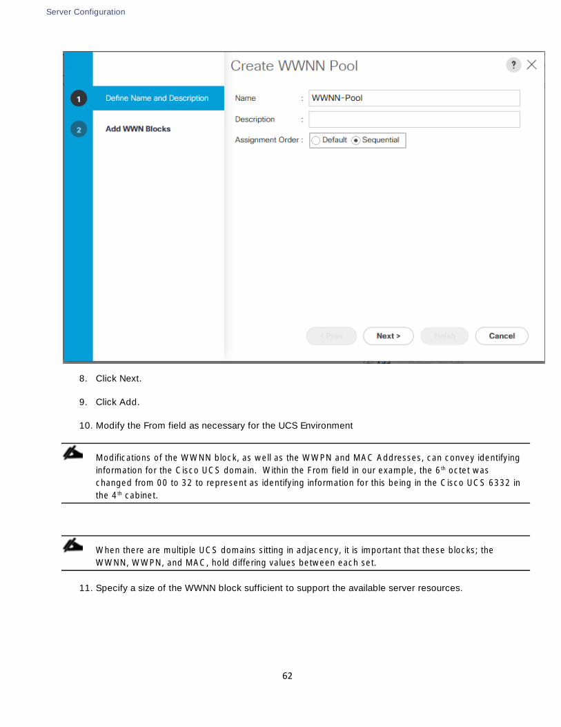
Server Configuration
62
8. Click Next.
9. Click Add.
10. Modify the From field as necessary for the UCS Environment
Modifications of the WWNN block, as well as the WWPN and MAC Addresses, can convey identifying
information for the Cisco UCS domain. Within the From field in our example, the 6th octet was
changed from 00 to 32 to represent as identifying information for this being in the Cisco UCS 6332 in
the 4th cabinet.
When there are multiple UCS domains sitting in adjacency, it is important that these blocks; the
WWNN, WWPN, and MAC, hold differing values between each set.
11. Specify a size of the WWNN block sufficient to support the available server resources.

Server Configuration
63
12. Click OK.
13. Click Finish and OK to complete creating the WWNN pool.
Create WWPN Pools
To configure the necessary WWPN pools for the Cisco UCS environment, complete the following steps:
1. In Cisco UCS Manager, click SAN on the left.
2. Select Pools > root.
3. In this procedure, two WWPN pools are created, one for each switching fabric.
4. Right-click WWPN Pools under the root organization.
5. Select Create WWPN Pool to create the WWPN pool.
6. Enter WWPN-Pool-A as the name of the WWPN pool.
7. Optional: Enter a description for the WWPN pool.
8. Select Sequential for Assignment Order.

Server Configuration
64
9. Click Next.
10. Click Add.
11. Specify a starting WWPN
For the FlexPod solution, the recommendation is to place 0A in the next-to-last octet of the starting
WWPN to identify all of the WWPNs as fabric A addresses. Merging this with the pattern we used for
the WWNN we see a WWPN block starting with 20:00:00:25:B5:32:0A:00
12. Specify a size for the WWPN pool that is sufficient to support the available blade or server resources.

Server Configuration
65
13. Click OK.
14. Click Finish.
15. In the confirmation message, click OK.
16. Right-click WWPN Pools under the root organization.
17. Select Create WWPN Pool to create the WWPN pool.
18. Enter WWPN-Pool-B as the name of the WWPN pool.
19. Optional: Enter a description for the WWPN pool.
20. Select Sequential for Assignment Order.
21. Click Next.
22. Click Add.
23. Specify a starting WWPN.

Server Configuration
66
For the FlexPod solution, the recommendation is to place 0B in the next-to-last octet of the starting
WWPN to identify all of the WWPNs as fabric A addresses. Merging this with the pattern we used for
the WWNN we see a WWPN block starting with 20:00:00:25:B5:32:0B:00.
24. Specify a size for the WWPN address pool that is sufficient to support the available blade or server
resources.
25. Click OK.
26. Click Finish.
27. In the confirmation message, click OK
Create VSAN
To configure the necessary virtual storage area networks (VSANs) for the Cisco UCS environment, com-
plete the following steps:
1. In Cisco UCS Manager, click the SAN on the left.
In this procedure, two VSANs are created.
2. Select SAN > SAN Cloud.
3. Right-click VSANs.
4. Select Create VSAN.
5. Enter VSAN-A as the name of the VSAN to be used for Fabric A
6. Leave FC Zoning set at Disabled.
7. Select Fabric A.
8. Enter a unique VSAN ID and a corresponding FCoE VLAN ID that matches the configuration in the
MDS switch for Fabric A. It is recommended to use the same ID for both parameters and to use
something other than 1.

Server Configuration
67
9. Click OK and then click OK again.
10. Under SAN Cloud, right-click VSANs.
11. Select Create VSAN.
12. Enter VSAN-B as the name of the VSAN to be used for Fabric B.
13. Leave FC Zoning set at Disabled.
14. Select Fabric B.
15. Enter a unique VSAN ID and a corresponding FCoE VLAN ID that matches the configuration in the
MDS switch for Fabric B. It is recommended use the same ID for both parameters and to use some-
thing other than 1.

Server Configuration
68
16. Click OK and then click OK again.
Create FC Uplink Port Channels
To create the FC Uplink Port Channels and assign the appropriate VSANs to them for the Cisco UCS
environment, complete the following steps:
1. In Cisco UCS Manager, click SAN on the left.
2. Select SAN > SAN Cloud.
3. Expand Fabric A and select FC Port Channels.
4. Right-click FC Port Channels and select Create FC Port Channel.
5. Set a unique ID for the port channel and provide a unique name for the port channel.
6. Click Next.
7. Select the ports connected to Cisco MDS A and use >> to add them to the port channel.
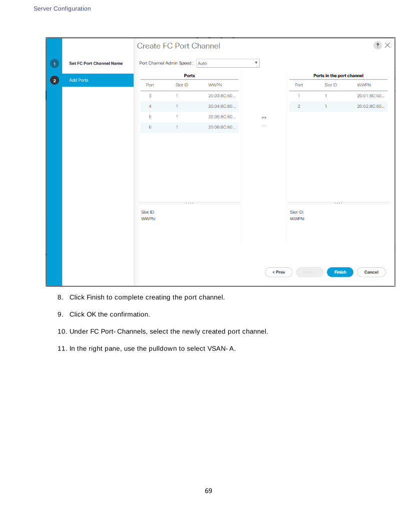
Server Configuration
69
8. Click Finish to complete creating the port channel.
9. Click OK the confirmation.
10. Under FC Port-Channels, select the newly created port channel.
11. In the right pane, use the pulldown to select VSAN-A.

Server Configuration
70
12. Click Save Changes to assign the VSAN.
13. Click OK.
14. Expand Fabric B and select FC Port Channels.
15. Right-click FC Port Channels and select Create FC Port Channel.
16. Set a unique ID for the port channel and provide a unique name for the port channel.
17. Click Next.
18. Select the ports connected to Cisco MDS B and use >> to add them to the port channel.
19. Click Finish to complete creating the port channel.
20. Click OK on the confirmation.
21. Under FC Port-Channels, select the newly created port channel.
22. In the right pane, use the pulldown to select VSAN-B.
23. Click Save Changes to assign the VSAN.
24. Click OK.
Create vHBA Templates
To create the necessary virtual host bus adapter (vHBA) templates for the Cisco UCS environment, complete
the following steps:
1. In Cisco UCS Manager, click SAN on the left.

Server Configuration
71
2. Select Policies > root.
3. Right-click vHBA Templates.
4. Select Create vHBA Template.
5. Enter vHBA-Template-A as the vHBA template name.
6. Keep Fabric A selected.
7. Leave Redundancy Type set to No Redundancy.
8. Select VSAN-A.
9. Leave Initial Template as the Template Type.
10. Select WWPN-Pool-A as the WWPN Pool.
11. Click OK to create the vHBA template.
12. Click OK.

Server Configuration
72
13. Right-click vHBA Templates.
14. Select Create vHBA Template.
15. Enter vHBA-Template-B as the vHBA template name.
16. Leave Redundancy Type set to No Redundancy.
17. Select Fabric B as the Fabric ID.
18. Select VSAN-B.
19. Leave Initial Template as the Template Type.

Server Configuration
73
20. Select WWPN-Pool-B as the WWPN Pool.
21. Click OK to create the vHBA template.
22. Click OK.
Create SAN Connectivity Policy
To configure the necessary Infrastructure SAN Connectivity Policy, complete the following steps:
1. In Cisco UCS Manager, click SAN on the left.
2. Select SAN > Policies > root.
3. Right-click SAN Connectivity Policies.
4. Select Create SAN Connectivity Policy.
5. Enter FC-Boot as the name of the policy.
6. Select the previously created WWNN-Pool for the WWNN Assignment.
7. Click the Add button at the bottom to add a vHBA.
8. In the Create vHBA dialog box, enter Fabric-A as the name of the vHBA.
9. Select the Use vHBA Template checkbox.
10. In the vHBA Template list, select vHBA-Template-A.
11. In the Adapter Policy list, select VMWare.

Server Configuration
74
12. Click OK.
13. Click the Add button at the bottom to add a second vHBA.
14. In the Create vHBA dialog box, enter Fabric-B as the name of the vHBA.
15. Select the Use vHBA Template checkbox.
16. In the vHBA Template list, select vHBA-Template-B.
17. In the Adapter Policy list, select VMWare.
18. Click OK.

Server Configuration
75
19. Click OK to create the SAN Connectivity Policy.
20. Click OK to confirm creation.
Create MAC Address Pools
To configure the necessary MAC address pools for the Cisco UCS environment, complete the following
steps:
1. In Cisco UCS Manager, click LAN on the left.
2. Select Pools > root.
In this procedure, two MAC address pools are created, one for each switching fabric.

Server Configuration
76
3. Right-click MAC Pools under the root organization.
4. Select Create MAC Pool to create the MAC address pool.
5. Enter MAC-Pool-A as the name of the MAC pool.
6. Optional: Enter a description for the MAC pool.
7. Select Sequential as the option for Assignment Order.
8. Click Next.
9. Click Add.
10. Specify a starting MAC address.
For the FlexPod solution, the recommendation is to place 0A in the next-to-last octet of the starting
MAC address to identify all of the MAC addresses as fabric A addresses. In our example, we carried
forward the UCS domain number information, providing us with 00:25:B5:32:0A:00 as our first MAC
address.
11. Specify a size for the MAC address pool that is sufficient to support the available blade or server re-
sources.

Server Configuration
77
12. Click OK.
13. Click Finish.
14. In the confirmation message, click OK.
15. Right-click MAC Pools under the root organization.
16. Select Create MAC Pool to create the MAC address pool.
17. Enter MAC-Pool-B as the name of the MAC pool.
18. Optional: Enter a description for the MAC pool.
19. Select Sequential as the option for Assignment Order.
20. Click Next.
21. Click Add.

Server Configuration
78
22. Specify a starting MAC address.
For the FlexPod solution, it is recommended to place 0B in the next to last octet of the starting MAC
address to identify all the MAC addresses in this pool as fabric B addresses. Once again, we have
carried forward in our example of also embedding the UCS domain number information giving us
00:25:B5:32:0B:00 as our first MAC address.
23. Specify a size for the MAC address pool that is sufficient to support the available blade or server re-
sources.
24. Click OK.
25. Click Finish.
26. In the confirmation message, click OK.
Create UUID Suffix Pool
To configure the necessary universally unique identifier (UUID) suffix pool for the Cisco UCS environment,
complete the following steps:
1. In Cisco UCS Manager, click Servers on the left.
2. Select Pools > root.
3. Right-click UUID Suffix Pools.
4. Select Create UUID Suffix Pool.
5. Enter UUID-Pool as the name of the UUID suffix pool.
6. Optional: Enter a description for the UUID suffix pool.
7. Keep the prefix at the derived option.
8. Select Sequential for the Assignment Order.
9. Click Next.
10. Click Add to add a block of UUIDs.
11. Keep the From field at the default setting.
12. Specify a size for the UUID block that is sufficient to support the available blade or server resources.
13. Click OK.
14. Click Finish.
15. Click OK.
Server Configuration
79
Create Server Pool
To configure the necessary server pool for the Cisco UCS environment, complete the following steps:
Consider creating unique server pools to achieve the granularity that is required in your environment.
1. In Cisco UCS Manager, click Servers on the left.
2. Select Pools > root.
3. Right-click Server Pools.
4. Select Create Server Pool.
5. Enter Infra-Pool as the name of the server pool.
6. Optional: Enter a description for the server pool.
7. Click Next.
8. Select two (or more) servers to be used for the VMware management cluster and click >> to add
them to the Infra-Pool server pool.
9. Click Finish.
10. Click OK.
Create VLANs
To configure the necessary virtual local area networks (VLANs) for the Cisco UCS environment, complete the
following steps:
1. In Cisco UCS Manager, click LAN on the left.
In this procedure, five unique VLANs are created. See Table 2
2. Select LAN > LAN Cloud.
3. Right-click VLANs.
4. Select Create VLANs.
5. Enter Native-VLAN as the name of the VLAN to be used as the native VLAN.
6. Keep the Common/Global option selected for the scope of the VLAN.
7. Enter the native VLAN ID.
8. Keep the Sharing Type as None.

Server Configuration
80
9. Click OK and then click OK again.
10. Expand the list of VLANs in the navigation pane, right-click the newly created Native-VLAN and se-
lect Set as Native VLAN.
11. Click Yes, and then click OK.
12. Right-click VLANs.
13. Select Create VLANs
14. Enter IB-MGMT as the name of the VLAN to be used for management traffic.
15. Keep the Common/Global option selected for the scope of the VLAN.
16. Enter the In-Band management VLAN ID.
17. Keep the Sharing Type as None.
18. Click OK, and then click OK again.
19. Right-click VLANs.

Server Configuration
81
20. Select Create VLANs.
21. Enter Infra-NFS as the name of the VLAN to be used for NFS.
22. Keep the Common/Global option selected for the scope of the VLAN.
23. Enter the Infrastructure NFS VLAN ID.
24. Keep the Sharing Type as None.
25. Click OK, and then click OK again.
26. Right-click VLANs.
27. Select Create VLANs.
28. Enter vMotion as the name of the VLAN to be used for vMotion.
29. Keep the Common/Global option selected for the scope of the VLAN.
30. Enter the vMotion VLAN ID.
31. Keep the Sharing Type as None.
32. Click OK, and then click OK again.
33. Select Create VLANs.
16. Enter VM-Traffic as the name of the VLAN to be used for VM Traffic.
34. Keep the Common/Global option selected for the scope of the VLAN.
35. Enter the VM-Traffic VLAN ID.
36. Keep the Sharing Type as None.
37. Click OK, and then click OK again.

Server Configuration
82
Modify Default Host Firmware Package
Firmware management policies allow the administrator to select the corresponding packages for a given
server configuration. These policies often include packages for adapter, BIOS, board controller, FC adapters,
host bus adapter (HBA) option ROM, and storage controller properties.
To create a firmware management policy for a given server configuration in the Cisco UCS environment,
complete the following steps:
1. In Cisco UCS Manager, click Servers on the left.
2. Select Policies > root.
3. Expand Host Firmware Packages.
4. Select default.
5. In the Actions pane, select Modify Package Versions.
6. Select the version 3.1(2f) for both the Blade and Rack Packages.
7. Click OK, then click OK again to modify the host firmware package.

Server Configuration
83
Set Jumbo Frames in Cisco UCS Fabric
To configure jumbo frames and enable quality of service in the Cisco UCS fabric, complete the following
steps:
1. In Cisco UCS Manager, click LAN on the left.
2. Select LAN > LAN Cloud > QoS System Class.
3. In the right pane, click the General tab.
4. On the Best Effort row, enter 9216 in the box under the MTU column.
5. Click Save Changes in the bottom of the window.
6. Click OK.
Only the Fibre Channel and Best Effort QoS System Classes are enabled in this FlexPod implementa-
tion. The UCS and Nexus switches are intentionally configured this way so that all IP traffic within the
FlexPod will be treated as Best Effort. Enabling the other QoS System Classes without having a com-
prehensive, end-to-end QoS setup in place can cause difficult to troubleshoot issues. For example,
NetApp storage controllers by default mark IP-based storage protocol packets with a CoS value of 4.
With the default configuration on the Nexus switches in this implementation, storage packets will pass
through the switches and into the Cisco UCS Fabric Interconnects with CoS 4 set in the packet header.
If the Gold QoS System Class in the Cisco UCS is enabled, these storage packets will be treated ac-
cording to that class and if Jumbo Frames is being used for the storage protocols, but the MTU of the
Gold QoS System Class is not set to Jumbo, packet drops will occur.
Create Local Disk Configuration Policy (Optional)
A local disk configuration for the Cisco UCS environment is necessary if the servers in the environment do
not have a local disk.
This policy should not be used on servers that contain local disks.

Server Configuration
84
To create a local disk configuration policy, complete the following steps:
1. In Cisco UCS Manager, click Servers on the left.
2. Select Policies > root.
3. Right-click Local Disk Config Policies.
4. Select Create Local Disk Configuration Policy.
5. Enter SAN-Boot as the local disk configuration policy name.
6. Change the mode to No Local Storage.
7. Click OK to create the local disk configuration policy.
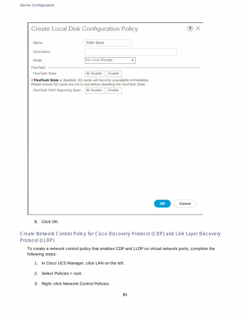
Server Configuration
85
8. Click OK.
Create Network Control Policy for Cisco Discovery Protocol (CDP) and Link Layer Discovery
Protocol (LLDP)
To create a network control policy that enables CDP and LLDP on virtual network ports, complete the
following steps:
1. In Cisco UCS Manager, click LAN on the left.
2. Select Policies > root.
3. Right-click Network Control Policies.

Server Configuration
86
4. Select Create Network Control Policy.
5. Enter Enable-CDP-LLDP as the policy name.
6. For CDP, select the Enabled option.
7. For LLDP, scroll down and select Enabled for both Transmit and Receive.
8. Click OK to create the network control policy.
9. Click OK.
Create Power Control Policy
To create a power control policy for the Cisco UCS environment, complete the following steps:
1. In Cisco UCS Manager, click Servers tab on the left.
2. Select Policies > root.
3. Right-click Power Control Policies.
4. Select Create Power Control Policy.
5. Enter No-Power-Cap as the power control policy name.

Server Configuration
87
6. Change the power capping setting to No Cap.
7. Click OK to create the power control policy.
8. Click OK.
Create Server Pool Qualification Policy (Optional)
To create an optional server pool qualification policy for the Cisco UCS environment, complete the following
steps:
This example creates a policy for Cisco UCS B-Series and Cisco UCS C-Series servers with the Intel
E2660 v4 Xeon Broadwell processors.
1. In Cisco UCS Manager, click Servers on the left.
2. Select Policies > root.
3. Right-click Server Pool Policy Qualifications.
4. Select Create Server Pool Policy Qualification.
5. Name the policy UCS-Broadwell.
6. Select Create CPU/Cores Qualifications.

Server Configuration
88
7. Select Xeon for the Processor/Architecture.
8. Enter UCS-CPU-E52660E as the PID.
9. Click OK to create the CPU/Core qualification.
10. Click OK to create the policy then OK for the confirmation.
Create Server BIOS Policy
To create a server BIOS policy for the Cisco UCS environment, complete the following steps:
1. In Cisco UCS Manager, click Servers on the left.
2. Select Policies > root.
3. Right-click BIOS Policies.
4. Select Create BIOS Policy.
5. Enter VM-Host as the BIOS policy name.
6. Change the Quiet Boot setting to disabled.
7. Change Consistent Device Naming to enabled.

Server Configuration
89
8. Click the Processor tab on the left.
9. Set the following within the Processor tab:
Processor C State -> disabled a.
Processor C1E -> disabled b.
Processor C3 Report -> disabled c.
Processor C7 Report -> disabled d.

Server Configuration
90
10. Scroll down to the remaining Processor options, and select:
Energy Performance -> performance a.
Frequency Floor Override -> enabled b.
DRAM Clock Throttling -> performance c.

Server Configuration
91
11. Click the RAS Memory option, and select:
LV DDR Mode -> performance-mode a.
12. Click Finish to create the BIOS policy.
13. Click OK.
Update the Default Maintenance Policy
To update the default Maintenance Policy, complete the following steps:
1. In Cisco UCS Manager, click Servers on the left.
2. Select Policies > root.
3. Select Maintenance Policies > default.
4. Change the Reboot Policy to User Ack.
5. Select delegate maintenance windows to server administrators.

Server Configuration
92
6. Click Save Changes.
7. Click OK to accept the change.
Create vNIC Templates
To create multiple virtual network interface card (vNIC) templates for the Cisco UCS environment, complete
the following steps. A total of 2 vNIC Templates will be created.
Create Infrastructure vNICs
1. In Cisco UCS Manager, click LAN on the left.
2. Select Policies > root.
3. Right-click vNIC Templates.
4. Select Create vNIC Template.
5. Enter Infra-A as the vNIC template name.
6. Keep Fabric A selected.
7. Select the Enable Failover checkbox.
Selecting Failover is a critical step to improve link failover time by handling it at the hardware level, and
to guard against NIC any potential for NIC failure not being detected by the virtual switch.
8. Select Primary Template for Redundancy Type.
9. Leave the Peer Redundancy Template set to <not set>.
10. Under Target, make sure that only the Adapter checkbox is selected.

Server Configuration
93
11. Select Updating Template as the Template Type.
12. Under VLANs, select the checkboxes for IB-MGMT, Infra-NFS, vMotion VM-Traffic, and Native-
VLAN VLANs.
13. Set Native-VLAN as the native VLAN.
14. Select vNIC Name for the CDN Source.
15. For MTU, enter 9000.
16. In the MAC Pool list, select MAC-Pool-A.
17. In the Network Control Policy list, select Enable-CDP-LLDP.

Server Configuration
94
18. Click OK to create the vNIC template.
19. Click OK.
Create the secondary redundancy template Infra-B:
1. Select LAN on the left.
2. Select Policies > root.
3. Right-click vNIC Templates.

Server Configuration
95
4. Select Create vNIC Template
5. Enter Infra-B as the vNIC template name.
6. Select Fabric B.
7. Select the Enable Failover checkbox.
8. Set Redundancy Type to Secondary Template.
9. Select Infra-A for the Peer Redundancy Template.
10. In the MAC Pool list, select MAC-Pool-B. The MAC Pool is all that needs to be selected for the Sec-
ondary Template.
11. Click OK to create the vNIC template.
12. Click OK.
Create LAN Connectivity Policy for FC Boot
To configure the necessary Infrastructure LAN Connectivity Policy, complete the following steps:
1. In Cisco UCS Manager, click LAN on the left.
2. Select LAN > Policies > root.
3. Right-click LAN Connectivity Policies.
4. Select Create LAN Connectivity Policy.
5. Enter FC-Boot as the name of the policy.
6. Click the upper Add button to add a vNIC.
7. In the Create vNIC dialog box, enter 00-Infra-A as the name of the vNIC.
8. Select the Use vNIC Template checkbox.
9. In the vNIC Template list, select Infra-A.
10. In the Adapter Policy list, select VMWare.
11. Click OK to add this vNIC to the policy.

Server Configuration
96
12. Click the upper Add button to add another vNIC to the policy.
13. In the Create vNIC box, enter 01-Infra-B as the name of the vNIC.
14. Select the Use vNIC Template checkbox.
15. In the vNIC Template list, select Infra-B.
16. In the Adapter Policy list, select VMWare.
17. Click OK to add the vNIC to the policy.

Server Configuration
97
18. Click OK, then click OK again to create the LAN Connectivity Policy.
Create vMedia Policy for VMware ESXi 6.5a Install Boot
In the NetApp ONTAP setup steps an HTTP web server is required, which will be used for hosting ONTAP as
well as VMware software. The vMedia Policy created will map the VMware ESXi 6.5a ISO to the Cisco UCS
server in order to boot the ESXi installation. To create this policy, complete the following steps:
1. In Cisco UCS Manager, select Servers on the left.
2. Select Policies > root.
3. Right-click vMedia Policies.
4. Select Create vMedia Policy.

Server Configuration
98
5. Name the policy ESXi-6.5a-HTTP.
6. Mounts ISO for ESXi 6.5a
7. Click Add.
8. Name the mount ESXi-6.5a-HTTP.
9. Select the CDD Device Type.
10. Select the HTTP Protocol.
11. Enter the IP Address of the web server.
Since DNS server IPs were not entered into the KVM IP earlier, it is necessary to enter the IP of the
web server instead of the hostname.
12. Enter VMware-VMvisor-Installer-201701001-4887370.x86_64.iso as the Remote File name.
This VMware ESXi 6.5a ISO can be downloaded from VMware Downloads.
13. Enter the web server path to the ISO file in the Remote Path field.

Server Configuration
99
14. Click OK to create the vMedia Mount.
15. Click OK then OK again to complete creating the vMedia Policy.
For any new servers added to the Cisco UCS environment the vMedia service profile template can be
used to install the ESXi host. On first boot the host will boot into the ESXi installer since the SAN
mounted disk is empty. After ESXi is installed, the vMedia will not be referenced as long as the boot
disk is accessible.
Create FC Boot Policy
This procedure applies to a Cisco UCS environment in which two Fibre Channel logical interfaces (LIFs) are
on cluster node 1 (fcp_lif01a and fcp_lif01b) and two Fibre Channel LIFs are on cluster node 2 (fcp_lif02a
andfcp_lif02b). Also, it is assumed that the A LIFs are connected to Fabric A (Cisco UCS Fabric Interconnect
A) and the B LIFs are connected to Fabric B (Cisco UCS Fabric Interconnect B).
One boot policy is configured in this procedure. The policy configures the primary target to
be fcp_lif01a.
To create a boot policy for the Cisco UCS environment, complete the following steps:

Server Configuration
100
1. In Cisco UCS Manager, click Servers on the left.
2. Select Policies > root.
3. Right-click Boot Policies.
4. Select Create Boot Policy.
5. Enter Boot-Fabric-A as the name of the boot policy.
6. Optional: Enter a description for the boot policy.
Do not select the Reboot on Boot Order Change checkbox.
7. Keep the Reboot on Boot Order Change option cleared.
8. Expand the Local Devices drop-down menu and select Add Remote CD/DVD.
9. Expand the vHBAs drop-down menu and select Add SAN Boot.
10. Select the Primary for type field.
11. Enter Fabric-A in vHBA field.
12. Click OK.
13. From the vHBA drop-down menu, select Add SAN Boot Target.
14. Keep 0 as the value for Boot Target LUN.

Server Configuration
101
15. Enter the WWPN for fcp_lif01a
To obtain this information, log in to the storage cluster and run the network interface show command
16. Select Primary for the SAN boot target type.
17. Click OK to add the SAN boot target.
18. From the vHBA drop-down menu, select Add SAN Boot Target.
19. Enter 0 as the value for Boot Target LUN.
20. Enter the WWPN for fcp_lif02a.
21. Click OK to add the SAN boot target.
22. From the vHBA drop-down menu, select Add SAN Boot.
23. In the Add SAN Boot dialog box, enter Fabric-B in the vHBA box.
24. The SAN boot type should automatically be set to Secondary.
25. Click OK to add the SAN boot.
26. From the vHBA drop-down menu, select Add SAN Boot Target.
27. Keep 0 as the value for Boot Target LUN.
28. Enter the WWPN for fcp_lif01b.

Server Configuration
102
29. Select Primary for the SAN boot target type.
30. Click OK to add the SAN boot target.
31. From the vHBA drop-down menu, select Add SAN Boot Target.
32. Keep 0 as the value for Boot Target LUN.
33. Enter the WWPN for fcp_lif02b.
34. Click OK to add the SAN boot target.
35. Expand CIMC Mounted Media and select Add CIMC Mounted CD/DVD.
36. Click OK, then click OK again to create the boot policy.

Server Configuration
103
Create Service Profile Templates
In this procedure, one service profile template for Infrastructure ESXi hosts is created for Fabric A boot.
To create the service profile template, complete the following steps:
1. In Cisco UCS Manager, click Servers on the left.
2. Select Service Profile Templates > root.
3. Right-click root.
4. Select Create Service Profile Template to open the Create Service Profile Template wizard.
5. Enter VM-Host-Infra-FC-A as the name of the service profile template. This service profile tem-
plate is configured to boot from storage node 1 on fabric A.
6.
7. Under UUID, select UUID_Pool as the UUID pool.
8. Click Next.

Server Configuration
104
Configure Storage Provisioning
1. If you have servers with no physical disks, click on the Local Disk Configuration Policy and select the
SAN-Boot Local Storage Policy. Otherwise, select the default Local Storage Policy.
2. Click Next.
Configure Networking Options
1. Keep the default setting for Dynamic vNIC Connection Policy.
2. connectivity.
3. Select FC-Boot from the LAN Connectivity Policy pull-down.
4. Leave Initiator Name Assignment at <not set>.
5. Click Next.
Configure Storage Options
1. i-
.
2. Select the FC-Boot option from the SAN Connectivity Policy drop-down list.

Server Configuration
105
3. Click Next.
Configure Zoning Options
1. Click Next.
Configure vNIC/HBA Placement
1. leave the placement policy
2. Click Next.
Configure vMedia Policy
1. Do not select a vMedia Policy.
2. Click Next.
Configure Server Boot Order
1. Select Boot-FC-A for Boot Policy.

Server Configuration
106
2. Click Next.
Configure Maintenance Policy
1. Change the Maintenance Policy to default.

Server Configuration
107
2. Click Next.
Configure Server Assignment
To configure server assignment, complete the following steps:
1. In the Pool Assignment list, select Infra-Pool.
2. Select Down as the power state to be applied when the profile is associated with the server.
3. Optional: select -Bro
4. Expand Firmware Management at the bottom of the page and select the default policy.
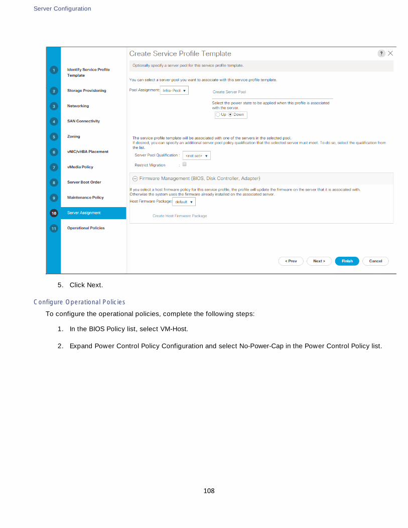
Server Configuration
108
5. Click Next.
Configure Operational Policies
To configure the operational policies, complete the following steps:
1. In the BIOS Policy list, select VM-Host.
2. Expand Power Control Policy Configuration and select No-Power-Cap in the Power Control Policy list.

Server Configuration
109
3. Click Finish to create the service profile template.
4. Click OK in the confirmation message.
Create vMedia-Enabled Service Profile Template
To create a service profile template with vMedia enabled, complete the following steps:
1. Connect to UCS Manager and click Servers on the left.
2. Select Service Profile Templates > root > Service Template VM-Host-Infra-FC-A.
3. Right-click VM-Host-Infra-FC-A and select Create a Clone.
4. Name the clone VM-Host-Infra-FC-A-vM.
5. Select the newly-created VM-Host-Infra-FC-A-vM and select the vMedia Policy tab on the right.
6. Click Modify vMedia Policy.
7. Select the ESXi-6.5a-HTTP vMedia Policy and click OK.
8. Click OK to confirm.

Server Configuration
110
Create Service Profiles
To create service profiles from the service profile template, complete the following steps:
1. Connect to UCS Manager and click Servers on the left.
2. Select Service Profile Templates > root > Service Template VM-Host-Infra-FC-A-vM.
3. Right-click VM-Host-Infra-FC-A and select Create Service Profiles from Template.
4. Enter VM-Host-Infra-0 as the service profile prefix.
5. Enter 1 .
6. Enter 2
7. Click OK to create the service profiles.
8. Click OK in the confirmation message.
9. When VMware ESXi 6.5a has been installed on the hosts, the host Service Profiles can be bound to
the VM-Host-Infra-FC-A Service Profile Template to remove the vMedia Mapping from the host.
Add More Servers to FlexPod Unit
Additional server pools, service profile templates, and service profiles can be created in the respective
organizations to add more servers to the FlexPod unit. All other pools and policies are at the root level and
can be shared among the organizations.
Gather Necessary Information
After the Cisco UCS service profiles have been created, each infrastructure server in the environment will
have a unique configuration. To proceed with the FlexPod deployment, specific information must be
gathered from each Cisco UCS server and from the NetApp controllers. Insert the required information into
Table 6 and Table 7 below.

Server Configuration
111
Table 6 WWPNs from NetApp Storage
SVM Adapter MDS Switch Target: WWPN
Infra-SVM fcp_lif01a Fabric A <fcp_lif01a-wwpn>
fcp_lif01b Fabric B <fcp_lif01b-wwpn>
fcp_lif02a Fabric A <fcp_lif02a-wwpn>
fcp_lif02b Fabric B <fcp_lif02b-wwpn>
To obtain the FC WWPNs, run the network interface show command on the storage cluster manage-
ment interface .
Table 7 WWPNs for Cisco UCS Service Profiles
Cisco UCS Service Profile Name MDS Switch Initiator WWPN
VM-Host-Infra-01 Fabric A vm-host-infra-01-wwpna
Fabric B vm-host-infra-01-wwpnb
VM-Host-Infra-02 Fabric A vm-host-infra-02-wwpna
Fabric B vm-host-infra-02-wwpnb
To obtain the FC vHBA WWPN information in Cisco UCS Manager GUI, go to Servers > Service Profiles
> root. Click each service profile and then click the “Storage” tab, then “vHBAs” tab on the right. The
WWPNs are displayed in the table at the bottom of the page.

Server Configuration
112
SAN Switch Configuration
This section provides a detailed procedure for configuring the Cisco MDS 9000s for use in a FlexPod
environment. Follow these steps precisely because failure to do so could result in an improper configuration.
If directly connecting storage to the Cisco UCS fabric interconnects, skip this section.
Physical Connectivity
FlexPod Cabling
FlexPod Cisco MDS Base
The following procedures describe how to configure the Cisco Nexus switches for use in a base FlexPod
environment. This procedure assumes you are using the Cisco MDS 9148s with NX-OS.
Set Up Initial Configuration
Cisco MDS 9148S A
To set up the initial configuration for the Cisco MDS A switch, <mds-A-hostname>, complete the following
steps:
On initial boot and connection to the serial or console port of the switch, the NX-OS setup should au-
tomatically start and attempt to enter Power on Auto Provisioning
1. Configure the switch using the command line.
Do you want to enforce secure password standard (yes/no) [y]: Enter
Enter the password for "admin": <password>
Confirm the password for "admin": <password>
Would you like to enter the basic configuration dialog (yes/no): yes
Create another login account (yes/no) [n]: Enter
Configure read-only SNMP community string (yes/no) [n]: Enter
Configure read-write SNMP community string (yes/no) [n]: Enter
Enter the switch name : <mds-A-hostname> Enter
Continue with Out-of-band (mgmt0) management configuration? (yes/no) [y]: Enter
Mgmt0 IPv4 address : <mds-A-mgmt0-ip> Enter
Mgmt0 IPv4 netmask : <mds-A-mgmt0-netmask> Enter
Configure the default gateway? (yes/no) [y]: Enter
IPv4 address of the default gateway : <mds-A-mgmt0-gw> Enter
Configure advanced IP options? (yes/no) [n]: Enter
Enable the ssh service? (yes/no) [y]: Enter

Server Configuration
113
Type of ssh key you would like to generate (dsa/rsa) [rsa]: Enter
Number of rsa key bits <1024-2048> [1024]: Enter
Enable the telnet service? (yes/no) [n]: Enter
Configure congestion/no_credit drop for fc interfaces? (yes/no) [y]: Enter
Enter the type of drop to configure congestion/no_credit drop? (con/no) [c]: Enter
Enter milliseconds in multiples of 10 for congestion-drop for port mode F
in range (<100-500>/default), where default is 500. [d]: Enter
Enable the http-server? (yes/no) [y]: Enter
Configure timezone? (yes/no) [n]: Enter
Configure summertime? (yes/no) [n]: Enter
Configure the ntp server? (yes/no) [n]: yes
NTP server IPv4 address : <switch-a-ntp-ip>
Configure default switchport interface state (shut/noshut) [shut]: Enter
Configure default switchport trunk mode (on/off/auto) [on]: Enter
Configure default switchport port mode F (yes/no) [n]: yes
Configure default zone policy (permit/deny) [deny]: Enter
Enable full zoneset distribution? (yes/no) [n]: yes
Configure default zone mode (basic/enhanced) [basic]: Enter
2. Review the configuration.
Would you like to edit the configuration? (yes/no) [n]: Enter
Use this configuration and save it? (yes/no) [y]: Enter
Cisco MDS 9148S B
To set up the initial configuration for the Cisco MDS B switch, <mds-B-hostname>, complete the following
steps:
On initial boot and connection to the serial or console port of the switch, the NX-OS setup should au-
tomatically start and attempt to enter Power on Auto Provisioning
1. Configure the switch using the command line.
Do you want to enforce secure password standard (yes/no) [y]: Enter
Enter the password for "admin": <password>
Confirm the password for "admin": <password>
Would you like to enter the basic configuration dialog (yes/no): yes
Create another login account (yes/no) [n]: Enter
Configure read-only SNMP community string (yes/no) [n]: Enter
Configure read-write SNMP community string (yes/no) [n]: Enter
Enter the switch name : <mds-B-hostname> Enter

Server Configuration
114
Continue with Out-of-band (mgmt0) management configuration? (yes/no) [y]: Enter
Mgmt0 IPv4 address : <mds-B-mgmt0-ip> Enter
Mgmt0 IPv4 netmask : <mds-B-mgmt0-netmask> Enter
Configure the default gateway? (yes/no) [y]: Enter
IPv4 address of the default gateway : <mds-B-mgmt0-gw> Enter
Configure advanced IP options? (yes/no) [n]: Enter
Enable the ssh service? (yes/no) [y]: Enter
Type of ssh key you would like to generate (dsa/rsa) [rsa]: Enter
Number of rsa key bits <1024-2048> [1024]: Enter
Enable the telnet service? (yes/no) [n]: Enter
Configure congestion/no_credit drop for fc interfaces? (yes/no) [y]: Enter
Enter the type of drop to configure congestion/no_credit drop? (con/no) [c]: Enter
Enter milliseconds in multiples of 10 for congestion-drop for port mode F
in range (<100-500>/default), where default is 500. [d]: Enter
Enable the http-server? (yes/no) [y]: Enter
Configure timezone? (yes/no) [n]: Enter
Configure summertime? (yes/no) [n]: Enter
Configure the ntp server? (yes/no) [n]: yes
NTP server IPv4 address : <<var_global_ntp_server_ip>>
Configure default switchport interface state (shut/noshut) [shut]: Enter
Configure default switchport trunk mode (on/off/auto) [on]: Enter
Configure default switchport port mode F (yes/no) [n]: yes
Configure default zone policy (permit/deny) [deny]: Enter
Enable full zoneset distribution? (yes/no) [n]: yes
Configure default zone mode (basic/enhanced) [basic]: Enter
2. Review the configuration.
Would you like to edit the configuration? (yes/no) [n]: Enter
Use this configuration and save it? (yes/no) [y]: Enter
FlexPod Cisco MDS Switch Configuration
Enable Licenses
Cisco MDS 9148S A and Cisco MDS 9148S B
To enable the correct features on the Cisco MDS switches, complete the following steps:
1. Log in as admin

Server Configuration
115
2. Run the following commands:
configure terminal
feature npiv
feature fport-channel-trunk
Configure Individual Ports
Cisco MDS 9148S A
To configure individual ports and port-channels for switch A, complete the following step:
In this step and in further sections, configure the <ucs-6248-clustername> and <ucs-6332-
clustername> interfaces as appropriate to your deployment.
From the global configuration mode, run the following commands:
interface fc1/1
switchport description <st-node01>:0e
switchport trunk mode off
port-license acquire
no shut
interface fc1/2
switchport description <st-node02>:0e
switchport trunk mode off
port-license acquire
no shutdown
exit
interface fc1/9
switchport description <ucs-6248-clustername>-a:1/31
port-license acquire
channel-group 110
no shutdown
exit
interface fc1/10
switchport description <ucs-6248-clustername>-a:1/32
port-license acquire
channel-group 110
no shutdown
exit
interface fc1/11
switchport description <ucs-6332-clustername>-a:1/1
port-license acquire
channel-group 112
no shutdown
exit
interface fc1/12
switchport description <ucs-6332-clustername>-a:1/2
port-license acquire
channel-group 112
no shutdown
exit
interface port-channel110
channel mode active
switchport mode F
switchport trunk allowed vsan <vsan-a-id>
switchport description <ucs-6248-clustername>
switchport rate-mode dedicated

Server Configuration
116
interface port-channel112
channel mode active
switchport mode F
switchport trunk allowed vsan <vsan-a-id>
switchport description <ucs-6332-clustername>
switchport rate-mode dedicated
Create Port Descriptions - Fabric B
To configure individual ports and port-channels for switch B, complete the following step:
From the global configuration mode, run the following commands:
interface fc1/1
switchport description <st-node01>:0f
switchport trunk mode off
port-license acquire
no shut
interface fc1/2
switchport description <st-node02>:0f
switchport trunk mode off
port-license acquire
no shutdown
exit
interface fc1/9
switchport description <ucs-6248-clustername>-b:1/31
port-license acquire
channel-group 111
no shutdown
exit
interface fc1/10
switchport description <ucs-6248-clustername>-b:1/32
port-license acquire
channel-group 111
no shutdown
exit
interface fc1/11
switchport description <ucs-6332-clustername>-b:1/1
port-license acquire
channel-group 113
no shutdown
exit
interface fc1/12
switchport description <ucs-6332-clustername>-b:1/2
port-license acquire
channel-group 113
no shutdown
exit
interface port-channel111
channel mode active
switchport mode F
switchport trunk allowed vsan <vsan-b-id>
switchport description <ucs-6248-clustername>
switchport rate-mode dedicated
interface port-channel113
channel mode active
switchport mode F
switchport trunk allowed vsan <vsan-b-id>
switchport description <ucs-6332-clustername>
switchport rate-mode dedicated

Server Configuration
117
Create VSANs
Cisco MDS 9148S A
To create the necessary VSANs for fabric A and add ports to them, complete the following steps:
From the global configuration mode, run the following commands:
vsan database
vsan <vsan-a-id>
vsan <vsan-a-id> name Fabric-A
exit
zone smart-zoning enable vsan <vsan-a-id>
vsan database
vsan <vsan-a-id> interface fc1/1
vsan <vsan-a-id> interface fc1/2
vsan <vsan-a-id> interface port-channel110
vsan <vsan-a-id> interface port-channel112
Cisco MDS 9148S B
To create the necessary VSANs for fabric A and add ports to them, complete the following steps:
From the global configuration mode, run the following commands:
vsan database
vsan <vsan-b-id>
vsan <vsan-b-id> name Fabric-B
exit
zone smart-zoning enable vsan <vsan-b-id>
vsan database
vsan <vsan-b-id> interface fc1/1
vsan <vsan-b-id> interface fc1/2
vsan <vsan-b-id> interface port-channel111
vsan <vsan-b-id> interface port-channel113
Create Device Aliases
Cisco MDS 9148S A
To create device aliases for Fabric A that will be used to create zones, complete the following steps:
From the global configuration mode, run the following commands:
configure terminal
device-alias database
device-alias name Infra-SVM-fcp_lif01a pwwn <fcp_lif01a-wwpn>
device-alias name Infra-SVM-fcp_lif02a pwwn <fcp_lif02a-wwpn>
device-alias name VM-Host-Infra-01-A pwwn <vm-host-infra-01-wwpna>
device-alias name VM-Host-Infra-02-A pwwn <vm-host-infra-02-wwpna>
device-alias commit
Cisco MDS 9148S B
To create device aliases for Fabric B that will be used to create zones, complete the following steps:
From the global configuration mode, run the following commands:
configure terminal
device-alias database
device-alias name Infra-SVM-fcp_lif01b pwwn <fcp_lif01b-wwpn>
device-alias name Infra-SVM-fcp_lif02b pwwn <fcp_lif02b-wwpn>
device-alias name VM-Host-Infra-01-B pwwn <vm-host-infra-01-wwpnb>

Server Configuration
118
device-alias name VM-Host-Infra-02-B pwwn <vm-host-infra-02-wwpnb>
device-alias commit
Create Zones
Cisco MDS 9148S A
To create the required zones on Fabric A, run the following commands:
configure terminal
zone name VM-Host-Infra-01-A vsan <vsan-a-id>
member device-alias VM-Host-Infra-01-A init
member device-alias Infra-SVM-fcp_lif01a target
member device-alias Infra-SVM-fcp_lif02a target
exit
zone name VM-Host-Infra-02-A vsan <vsan-a-id>
member device-alias VM-Host-Infra-02-A init
member device-alias Infra-SVM-fcp_lif01a target
member device-alias Infra-SVM-fcp_lif02a target
exit
zoneset name Fabric-A vsan <vsan-a-id>
member VM-Host-Infra-01-A
member VM-Host-Infra-02-A
exit
zoneset activate name Fabric-A vsan <vsan-a-id>
exit
show zoneset active vsan <vsan-a-id>
Cisco MDS 9148S B
To create the required zones on Fabric B, run the following commands:
configure terminal
zone name VM-Host-Infra-01-B vsan <vsan-b-id>
member device-alias VM-Host-Infra-01-B init
member device-alias Infra-SVM-fcp_lif01b target
member device-alias Infra-SVM-fcp_lif02b target
exit
zone name VM-Host-Infra-02-B vsan <vsan-b-id>
member device-alias VM-Host-Infra-02-B init
member device-alias Infra-SVM-fcp_lif01b target
member device-alias Infra-SVM-fcp_lif02b target
exit
zoneset name Fabric-B vsan <vsan-b-id>
member VM-Host-Infra-01-B
member VM-Host-Infra-02-B
exit
zoneset activate name Fabric-B vsan <vsan-b-id>
exit
show zoneset active vsan <vsan-b-id>

Storage Configuration Boot LUNs
119
Storage Configuration Boot LUNs
ONTAP Boot Storage Setup
Create igroups
Create igroups by entering the following commands from the cluster management node SSH connection:
igroup create –vserver Infra-SVM –igroup VM-Host-Infra-01 –protocol fcp –ostype vmware –initiator
<vm-host-infra-01-wwpna>, <vm-host-infra-01-wwpnb>
igroup create –vserver Infra-SVM –igroup VM-Host-Infra-02 –protocol fcp –ostype vmware –initiator
<vm-host-infra-02-wwpna>, <vm-host-infra-02-wwpnb>
igroup create –vserver Infra-SVM –igroup MGMT-Hosts –protocol fcp –ostype vmware –initiator <vm-host-
infra-01-wwpna>, <vm-host-infra-01-wwpnb>, <vm-host-infra-02-wwpna>, <vm-host-infra-02-wwpnb>
Use the values listed in Error! Reference source not found. and Error! Reference source not found.
r the WWPN information.
To view the three igroups just created, type igroup show.
Map Boot LUNs to igroups
From the storage cluster management SSH connection, enter the following commands:
lun map –vserver Infra-SVM –volume esxi_boot –lun VM-Host-Infra-01 –igroup VM-Host-Infra-01 –lun-id 0
lun map –vserver Infra-SVM –volume esxi_boot –lun VM-Host-Infra-02 –igroup VM-Host-Infra-02 –lun-id 0

VMware vSphere 6.5a Setup
120
VMware vSphere 6.5a Setup
VMware ESXi 6.5a
This section provides detailed instructions for installing VMware ESXi 6.5a in an environment. After the
procedures are completed, two booted ESXi hosts will be provisioned.
Several methods exist for installing ESXi in a VMware environment. These procedures focus on how to use
the built-in keyboard, video, mouse (KVM) console and virtual media features in Cisco UCS Manager to map
remote installation media to individual servers and connect to their boot logical unit numbers (LUNs).
Download Cisco Custom Image for ESXi 6.5a
If the VMware ESXi custom image has not been downloaded, complete the following steps:
1. Click the following link: VMware vSphere Hypervisor (ESXi) 6.5a.
2. You will need a user id and password on vmware.com to download this software.
3. Download the .iso file.
Log in to Cisco UCS 6300/6200 Fabric Interconnect
Cisco UCS Manager
The Cisco UCS IP KVM enables the administrator to begin the installation of the operating system (OS)
through remote media. It is necessary to log in to the Cisco UCS environment to run the IP KVM.
To log in to the Cisco UCS environment, complete the following steps:
1. Open a web browser and enter the IP address for the Cisco UCS cluster address. This step launches
the Cisco UCS Manager application.
2. Click the Launch UCS Manager link under HTML to launch the HTML 5 UCS Manager GUI.
3. If prompted to accept security certificates, accept as necessary.
4. When prompted, enter admin as the user name and enter the administrative password.
5. To log in to Cisco UCS Manager, click Login.
6. From the main menu, click Servers on the left.
7. Select Servers > Service Profiles > root > VM-Host-Infra-01.
8. Right-click VM-Host-Infra-01 and select KVM Console.
9. Follow the prompts to launch the Java-based KVM console.

VMware vSphere 6.5a Setup
121
10. Select Servers > Service Profiles > root > VM-Host-Infra-02.
11. Right-click VM-Host-Infra-02. and select KVM Console.
12. Follow the prompts to launch the Java-based KVM console.
Set Up VMware ESXi Installation
ESXi Hosts VM-Host-Infra-01 and VM-Host-Infra-02
Skip this section if using vMedia policies. ISO file will already be connected to KVM.
To prepare the server for the OS installation, complete the following steps on each ESXi host:
1. In the KVM window, click Virtual Media.
2. Click Activate Virtual Devices
3. If prompted to accept an Unencrypted KVM session, accept as necessary.
4. Click Virtual Media and select Map CD/DVD.
5. Browse to the ESXi installer ISO image file and click Open.
6. Click Map Device.
7. Click the KVM tab to monitor the server boot.
Install ESXi
ESXi Hosts VM-Host-Infra-01 and VM-Host-Infra-02
To install VMware ESXi to the FC-bootable LUN of the hosts, complete the following steps on each host:
1. Boot the server by selecting Boot Server and click OK, then click OK again.
2. On reboot, the machine detects the presence of the ESXi installation media. Select the ESXi installer
from the boot menu that is displayed.
3. After the installer is finished loading, press Enter to continue with the installation.
4. Read and accept the end-user license agreement (EULA). Press F11 to accept and continue.
5. Select the LUN that was previously set up as the installation disk for ESXi and press Enter to continue
with the installation.
6. Select the appropriate keyboard layout and press Enter.
7. Enter and confirm the root password and press Enter.

VMware vSphere 6.5a Setup
122
8. The installer issues a warning that the selected disk will be repartitioned. Press F11 to continue with
the installation.
9. After the installation is complete, click on the Virtual Media tab and clear the checkmark next to the
ESXi installation media. Click Yes.
The ESXi installation image must be unmapped to make sure that the server reboots into ESXi and not
into the installer.
10. After the installation is complete, press Enter to reboot the server.
11. In Cisco UCS Manager, bind the current service profile to the non-vMedia service profile template to
prevent mounting the ESXi installation iso over HTTP.
Set Up Management Networking for ESXi Hosts
Adding a management network for each VMware host is necessary for managing the host. To add a
management network for the VMware hosts, complete the following steps on each ESXi host:
ESXi Host VM-Host-Infra-01 and VM-Host-Infra-02
To configure each ESXi host with access to the management network, complete the following steps:
1. After the server has finished rebooting, press F2 to customize the system.
2. Log in as root, enter the corresponding password, and press Enter to log in.
3. Select Troubleshooting Options and press Enter.
4. Select Enable ESXi Shell and press Enter.
5. Select Enable SSH and press Enter.
6. Press Esc to exit the Troubleshooting Options menu.
7. Select the Configure Management Network option and press Enter.
8. Select Network Adapters and press Enter.
9. Verify that the numbers in the Hardware Label field match the numbers in the Device Name field.

VMware vSphere 6.5a Setup
123
In lab testing, examples have been seen with the Cisco UCS C220 M4 server and VIC 1385/1387
where the vmnic and device ordering do not match. If this is the case, use the Consistent Device Nam-
ing (CDN) to note which vmnics are mapped to which vNICs and adjust the upcoming procedure ac-
cordingly.
10. Press Enter.
11. Select the VLAN (Optional) option and press Enter.
12. Enter the <ib-mgmt-vlan-id> and press Enter.
13. Select IPv4 Configuration and press Enter.
14. Select the Set static IPv4 address and network configuration option by using the space bar.
15. Enter the IP address for managing the first ESXi host.
16. Enter the subnet mask for the first ESXi host.
17. Enter the default gateway for the first ESXi host.
18. Press Enter to accept the changes to the IP configuration.
19. Select the IPv6 Configuration option and press Enter.
20. Using the spacebar, select Disable IPv6 (restart required) and press Enter.
21. Select the DNS Configuration option and press Enter.

VMware vSphere 6.5a Setup
124
Because the IP address is assigned manually, the DNS information must also be entered manually.
22. Enter the IP address of the primary DNS server.
23. Optional: Enter the IP address of the secondary DNS server.
24. Enter the fully qualified domain name (FQDN) for the first ESXi host.
25. Press Enter to accept the changes to the DNS configuration.
26. Press Esc to exit the Configure Management Network submenu.
27. Select Test Management Network to verify that the management network is set up correctly and
press Enter.
28. Press Enter to run the test, press Enter again once the test has completed, review environment if
there is a failure.
29. Re-select the Configure Management Network and press Enter.
30. Select the IPv6 Configuration option and press Enter.
31. Using the spacebar, select Disable IPv6 (restart required) and press Enter.
32. Press Esc to exit the Configure Management Network submenu.
33. Press Y to confirm the changes and reboot the ESXi host.
34. After the host reboots, log back into the VMware ESXi console interface.
35. Select Troubleshooting Options.
36. Select Enable ESXi Shell and press Enter.
37. Select Enable SSH and press Enter.
38. Press <esc> to return to the main ESXi console menu.
Reset VMware ESXi Host VMkernel Port vmk0 MAC Address (Optional)
ESXi Host VM-Host-Infra-01 and VM-Host-Infra-02
By default the MAC address of the management VMkernel port vmk0 is the same as the MAC address of the
addresses, a MAC address conflict will exist because vmk0 will retain the assigned MAC address. To reset
the MAC address of vmk0 to a random VMware-assigned MAC address, complete the following steps:
1. From the ESXi console menu main screen, type Ctrl-Alt-F1 to access the VMware console command
line interface. In the UCSM KVM, Ctrl-Alt-F1 appears in the list of Static Macros.
VMware vSphere 6.5a Setup
125
2. Log in as root.
3. -vmknic get a detailed listing of interface vmk0. vmk0 should be a part of the
IP address and netmask of vmk0.
4. -vmknic
5. To re- -vmknic a i <vmk0-ip> -n <vmk0-
6. Verify vmk0 has been re-added with a rando -vmknic
7.
8. Type Ctrl-Alt-F2 to return to the ESXi console menu interface.
Log in to VMware ESXi Hosts by Using VMware Host Client
ESXi Host VM-Host-Infra-01
To log in to the VM-Host-Infra-01 ESXi host by using the VMware Host Client, complete the following
steps:
1. Open a web browser on the management workstation and navigate to the VM-Host-Infra-01 man-
agement IP address.
2. Click Open the VMware Host Client.
3. Enter root for the user name.
4. Enter the root password.
5. Click Login to connect.
6. Repeat this process to log into VM-Host-Infra-02 in a separate browser tab or window.
Set Up VMkernel Ports and Virtual Switch
ESXi Host VM-Host-Infra-01 and VM-Host-Infra-02
To set up the VMkernel ports and the virtual switches on the ESXi hosts, complete the following steps:
1. From the Host Client, select Networking on the left.
2. In the center pane, select the Virtual switches tab.
3. Select vSwitch0.
4. Select Edit settings.
5. Change the MTU to 9000.

VMware vSphere 6.5a Setup
126
6. Click Save.
7. On the left, select Networking, then select the Port groups tab.
8. In the center pane, right-click VM Network and select Remove.
9. Click Remove to complete removing the port group.
10. In the center pane, select Add port group.
11. Name the port group IB-MGMT Network and enter <ib-mgmt-vlan-id> in the VLAN ID field, and
make sure Virtual switch vSwitch0 is selected.
12. Click Add to finalize the edits for the IB-MGMT Network.
13. At the top, select the VMkernel NICs tab.
14. Click Add VMkernel NIC.
15. For New port group, enter VMkernel-vMotion.
16. For Virtual switch, select vSwitch0.
17. Enter <vmotion-vlan-id> for the VLAN ID.
18. Change the MTU to 9000.
19. Select Static IPv4 settings and expand IPv4 settings.
20. Enter the ESXi host vMotion IP address and netmask.
21. Select the vMotion stack for TCP/IP stack.
22. Click Create.
23. Click Add VMkernel NIC.
24. For New port group, enter VMkernel-Infra-NFS
25. For Virtual switch, select vSwitch0.
26. Enter <infra-nfs-vlan-id> for the VLAN ID
27. Change the MTU to 9000.
28. Select Static IPv4 settings and expand IPv4 settings.
29. Enter the ESXi host Infrastructure NFS IP address and netmask.
30. Do not select any of the Services.

VMware vSphere 6.5a Setup
127
31. Click Create.
32. Select the Virtual Switches tab, then vSwitch0. The properties for vSwitch0 VMkernel NICs should be
similar to the following example:
33. Select the VMkernel NICs tab to confirm configured virtual adapters. The adapters listed should be
similar to the following example:
Install VMware Drivers for the Cisco Virtual Interface Card (VIC)
Download and extract the offline bundle for the following VMware VIC Driver to the Management
workstation:
fnic Driver version 1.6.0.28
ESXi Hosts VM-Host-Infra-01 and VM-Host-Infra-02
To install VMware VIC Drivers on the ESXi host VM-Host-Infra-01 and VM-Host-Infra-02, complete the
following steps:

VMware vSphere 6.5a Setup
128
1. From each Host Client, select Storage on the left.
2. Right-click datastore1 and select Browse.
3. In the Datastore browser, click Upload.
4. Navigate to the saved location for the downloaded VIC drivers and select fnic_driver_1.6.0.28-
offline_bundle-4179603.zip.
5. Click Open to upload the file to datastore1.
6. Make sure the file has been uploaded to both ESXi hosts.
7. Connect to each ESXi host through ssh from a shell connection or putty terminal.
8. Login as root with the root password.
9. Run the following command on each host:
esxcli software vib update -d /vmfs/volumes/datastore1/fnic_driver_1.6.0.28-
offline_bundle-4179603.zip
10. Reboot each host by typing reboot from the SSL interface after both commands have been run.
11. Log into the Host Client on each host once reboot is complete.
Mount Required Datastores
ESXi Hosts VM-Host-Infra-01 and VM-Host-Infra-02
To mount the required datastores, complete the following steps on each ESXi host:
1. From the Host Client, select Storage on the left.
2. In the center pane, select Datastores.
3. In the center pane, select New Datastore to add a new datastore.
4. In the New datastore popup, select Mount NFS datastore and click Next.
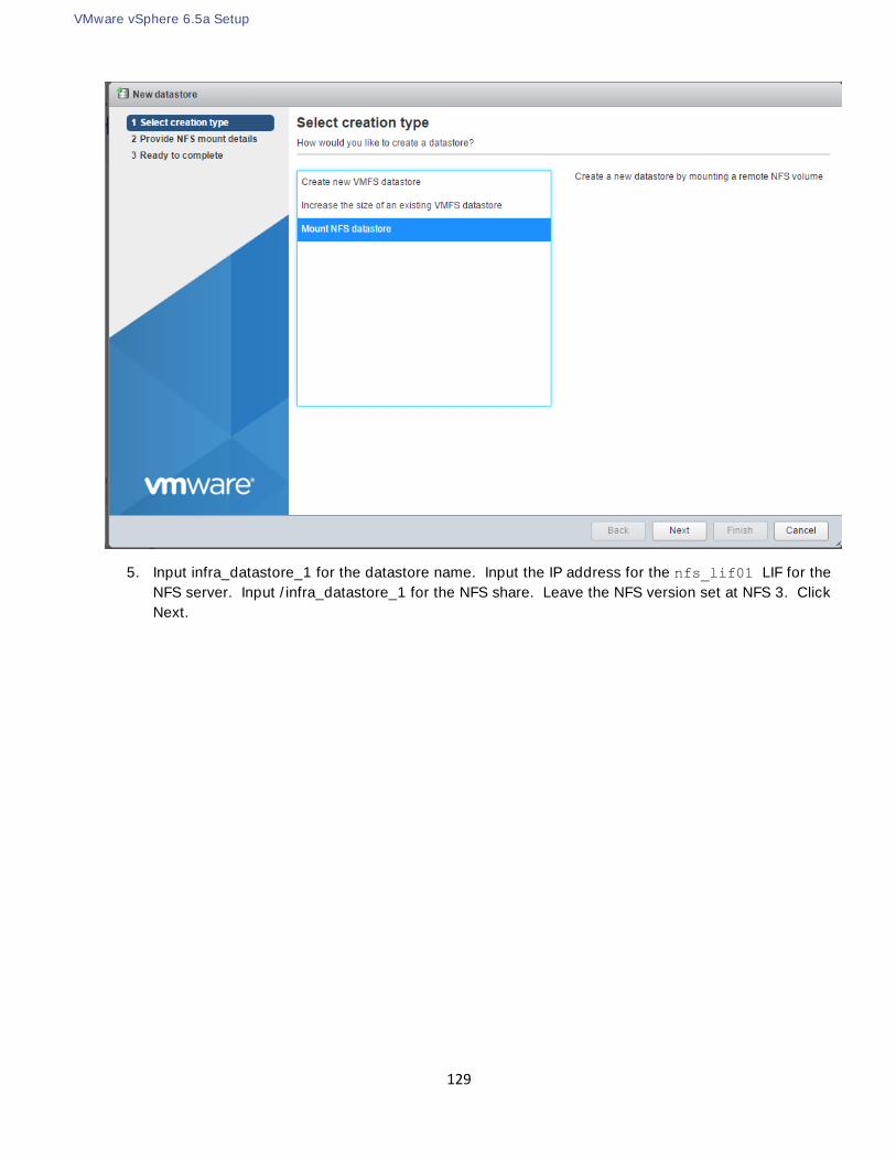
VMware vSphere 6.5a Setup
129
5. Input infra_datastore_1 for the datastore name. Input the IP address for the nfs_lif01 LIF for the
NFS server. Input /infra_datastore_1 for the NFS share. Leave the NFS version set at NFS 3. Click
Next.

VMware vSphere 6.5a Setup
130
6. Click Finish. The datastore should now appear in the datastore list.
7. In the center pane, select New Datastore to add a new datastore.
8. In the New datastore popup, select Mount NFS datastore and click Next.
9. Input infra_datastore_2 for the datastore name. Input the IP address for the nfs_lif02 LIF for the
NFS server. Input /infra_datastore_2 for the NFS share. Leave the NFS version set at NFS 3. Click
Next.
10. Click Finish. The datastore should now appear in the datastore list.
11. Mount both datastores on both ESXi hosts.

VMware vSphere 6.5a Setup
131
Configure NTP on ESXi Hosts
ESXi Hosts VM-Host-Infra-01 and VM-Host-Infra-02
To configure Network Time Protocol (NTP) on the ESXi hosts, complete the following steps on each host:
1. From the Host Client, select Manage on the left.
2. In the center pane, select the Time & date tab.
3. Click Edit settings.
4. Make sure Use Network Time Protocol (enable NTP client) is selected.
5. Use the pulldown to select Start and stop with host.
6. Enter the two Nexus switch NTP addresses in the NTP servers box separated by a comma.
7. Click Save to save the configuration changes.
8. Select Actions > NTP service > Start.
9. Verify that NTP service is now running and the clock is now set to approximately the correct time.
The NTP server time may vary slightly from the host time.

VMware vSphere 6.5a Setup
132
VMware vCenter 6.5
The procedures in the following subsections provide detailed instructions for installing the VMware vCenter
6.5 Server Appliance in an environment. After the procedures are completed, a VMware vCenter Server will
be configured.
Building the VMware vCenter Server Appliance
The VCSA deployment consists of 2 stages: install and configuration. To build the VMware vCenter virtual
machine, complete the following steps:
1. Locate and copy the VMware-VCSA-all-6.5.0-4944578.iso file to the desktop of the management
workstation. This ISO is for the VMware vSphere 6.5 vCenter Server Appliance.
2. Using ISO mounting software, mount the ISO image as a disk on the management workstation. (For
example, with the Mount command in Windows Server 2012).
3. In the mounted disk directory, navigate to the vcsa-ui-installer > win32 directory and double-click
installer.exe. The vCenter Server Appliance Installer wizard appear

VMware vSphere 6.5a Setup
133
4. Click Install to start the vCenter Server Appliance deployment wizard.
5. Click Next in the Introduction section.
6. Read and accept the license agreement and click Next.
7. Select deployment type section, select Embedded Platform Services Controller.

VMware vSphere 6.5a Setup
134
8. enter the ESXi host name or IP address, User name and Pass-
word.

VMware vSphere 6.5a Setup
135
9. Click Yes to accept the certificate.
10. appliance VM section. Click Next.

VMware vSphere 6.5a Setup
136
11. size section, Select the deployment size and Storage size. For example,
12. Click Next.

VMware vSphere 6.5a Setup
137
13. Select the infra_datastore_1. Click Next.

VMware vSphere 6.5a Setup
138
14. section, configure the below settings:
Choose a Network: IB-MGMT Network a.
IP version: IPV4 b.
IP assignment: static c.
System name: <vcenter-fqdn> d.
IP address: <vcenter-ip> e.
Subnet mask or prefix length: <vcenter-subnet-mask> f.
Default gateway: <vcenter-gateway> g.
DNS Servers: <dns-server> h.

VMware vSphere 6.5a Setup
139
15. Click Next.
16. Review all values and click Finish to complete the installation.
17. The vCenter appliance installation will take a few minutes to complete.

VMware vSphere 6.5a Setup
140
18. Click Continue to proceed with stage 2 configuration.
19. Click Next.
20. In the Appliance Configuration, configure the below settings:
Time Synchronization Mode: Synchronize time with NTP servers. a.
NTP Servers: <ntp_server_ip> b.
SSH access: Enabled. c.

VMware vSphere 6.5a Setup
141
21. Click Next.
22. Complete the SSO configuration as show below:

VMware vSphere 6.5a Setup
142
23. Click Next.
24.
25. Click Next.
26. Review the configuration and click Finish.
27. Click OK.

VMware vSphere 6.5a Setup
143
Setting Up VMware vCenter Server
1. Using a web browser, navigate to https://<vcenter-ip>/vsphere-client
2. Click Download Enhanced Authentication Plugin. Install the same by double clicking the downloaded
file.
3. Log in using the Single Sign-On username and password created during the vCenter installation.

VMware vSphere 6.5a Setup
144
4. Click
5. -
6. Click OK.
7. Right-click the data center FlexPod-DC in the list in the center pane. Click New Cluster.
8. Name the cluster FlexPod-Management.
9. Check the box to turn on DRS. Leave the default values.
10. Check the box to turn on vSphere HA. Leave the default values.

VMware vSphere 6.5a Setup
145
11. Click OK to create the new cluster.
12. On the left pane, double -
13. Click Clusters.
14. Under the Clusters pane, right-click FlexPod-Management and select Settings.
15. Select Configuration > General in the list on the left and select Edit to the right of General.
16. Select Datastore specified by host and click OK.

VMware vSphere 6.5a Setup
146
17. On the left, right-click FlexPod-Management and click Add Host.
18. In the Host field, enter either the IP address or the FQDN name of one of the VMware ESXi hosts.
Click Next.
19. Type root as the user name and the root password. Click Next to continue.
20. Click Yes to accept the certificate.
21. Review the host details and click Next to continue.
22. Assign a license or leave in evaluation mode and click Next to continue.
23. Click Next to continue.
24. Click Next to continue.
25. Review the configuration parameters and click Finish to add the host.

VMware vSphere 6.5a Setup
147
26. Repeat the steps 17 to 25 to add the remaining VMware ESXi hosts to the cluster.
Two VMware ESXi hosts will be added to the cluster.
Add AD User Authentication to vCenter (Optional)
If an AD Infrastructure is set up in this FlexPod environment, you can setup in AD and authenticate from
vCenter.
1. In the AD Infrastructure, using the Active Directory Users and Computers tool, setup a Domain Ad-
ministrator user with a user name such as flexadmin (FlexPod Admin).
2. Connect to https://<vcenter-ip>, and select Log in to vSphere Web Client.
3. Log in as [email protected] (or the SSO user set up in vCenter installation) with the corre-
sponding password.
4. Navigate to Home. In the center pane, select System Configuration under Administration.
5. On the left, select Nodes and under Nodes select the vCenter.
6. In the center pane, select the manage tab, and within the Settings select Active Directory and click
Join.
7. Fill in the AD domain name, the Administrator user, and the domain Administrator password. Click
OK.

VMware vSphere 6.5a Setup
148
8. On the left, right-click the vCenter and select Reboot.
9. Input a reboot reason and click OK. The reboot will take approximately 10 minutes for full vCenter
initialization.
10. Log back into the vCenter Web Client.
11. In the center pane, select System Configuration under Administration.
12. On the left, select Nodes and under Nodes select the vCenter.
13. In the center pane under the Manage tab, select Active Directory. Make sure your Active Directory
Domain is listed.
14. Navigate back to the vCenter Home.
15. In the center pane under Administration, select Roles.
16. On the left under Single Sign-On, select Configuration.
17. In the center pane, select the Identity Sources tab.
18. Click the green + sign to add an Identity Source.
19. Select the Active Directory (Integrated Windows Authentication) Identity source type.
20. Your AD domain name should be filled in. Leave Use machine account selected and click OK.
21. Your AD domain should now appear in the Identity Sources list.
22. On the left, under Single Sign-On, select Users and Groups.
23. In the center pane, select your AD domain for the Domain.
24. Make sure the FlexPod Admin user setup in step 1 appears in the list.
25. On the left under Administration, select Global Permissions.
26. Select the Manage tab, and click the green + sign to add a User or Group.
27. In the Global Permission Root - Add Permission window, click Add.
28. In the Select Users/Groups window, select your AD Domain.
29. Under Users and Groups, select either the FlexPod Admin user or the Domain Admins group.
The FlexPod Admin user was created in the Domain Admins group. The selection here depends on
whether the FlexPod Admin user will be the only user used in this FlexPod or you would like to add
other users later. By selecting the Domain Admins group, any user placed in that group in the AD do-
main will be able to login to vCenter as an Administrator.

VMware vSphere 6.5a Setup
149
30. Click Add, then click Check names to verify correctness of the names. Click OK to acknowledge the
correctness of the names.
31. Click OK to add the selected User or Group.
32. Verify the added User or Group is listed under Users and Groups and the Administrator role is as-
signed.
33. Click OK.
34. Log out and log back into the vCenter Web Client as the FlexPod Admin user. You will need to add
the domain name to the user, for example, flexadmin@domain.
Cisco UCS Manager Plug-in for VMware vSphere Web Client
The Cisco UCS Manager Plug-in for VMware vSphere Web Client allows administration of UCS domains
The capabilities of the plug-in include:
View Cisco UCS physical hierarchy
View inventory, installed firmware, faults, power and temperature statistics
Map the ESXi host to the physical server
Manage firmware for Cisco UCS B and C series servers
View VIF paths for servers
Launch the Cisco UCS Manager GUI
Launch the KVM consoles of UCS servers
Switch the existing state of the locator LEDs
The installation is only valid for VMware vCenter 5.5 or higher, and will require revisions of .NET Framework
4.5 and VMware PowerCLI 5.1 or greater.
Cisco UCS Manager Plug-in Installation
To begin the plug-in installation on a Windows system that meets the previously stated requirements,
complete the following steps:
1. Download the plugin and registration tool from:
https://software.cisco.com/download/release.html?mdfid=286282669&reltype=latest&relind=AVAIL
ABLE&dwnld=true&softwareid=286282010&catid=282558030&rellifecycle=&atcFlag=N&release=2.0.
1&dwldImageGuid=5963DCD457E74C173F61512F00BB6FE78C5D8B72
2. Place the downloaded ucs-vcplugin-2.0.1.zip file onto the web server used for hosting the ONTAP
software and VMware ESXi ISO.
3. Unzip the Cisco_UCS_Plugin_Registration_Tool_1_1_3.zip and open the executable file within it.
4. Leave Register Plugin selected for the Action, and fill in:

VMware vSphere 6.5a Setup
150
IP/Hostname a.
Username b.
Password c.
URL that plugin has been uploaded to d.
5. A pop- i-
ent.properties file on the VCSA in the /etc/vmware/vsphere-client directory.
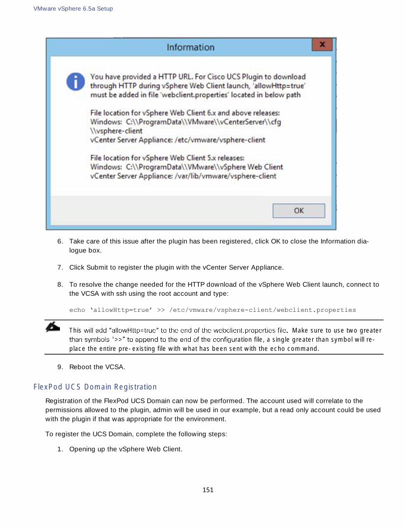
VMware vSphere 6.5a Setup
151
6. Take care of this issue after the plugin has been registered, click OK to close the Information dia-
logue box.
7. Click Submit to register the plugin with the vCenter Server Appliance.
8. To resolve the change needed for the HTTP download of the vSphere Web Client launch, connect to
the VCSA with ssh using the root account and type:
echo ‘allowHttp=true’ >> /etc/vmware/vsphere-client/webclient.properties
This Make sure to use two greater
ration file, a single greater than symbol will re-
place the entire pre-existing file with what has been sent with the echo command.
9. Reboot the VCSA.
FlexPod UCS Domain Registration
Registration of the FlexPod UCS Domain can now be performed. The account used will correlate to the
permissions allowed to the plugin, admin will be used in our example, but a read only account could be used
with the plugin if that was appropriate for the environment.
To register the UCS Domain, complete the following steps:
1. Opening up the vSphere Web Client.

VMware vSphere 6.5a Setup
152
2. Select the Home from the Navigator or pull-down options, and double click the Cisco UCS icon ap-
pearing in the Administration section.
3. Click the Register button and provide the following options in the Register UCS Domain dialogue box
that appears:
UCS Hostname/IP a.
Username b.
Password c.
Port (if different than 443) d.
Leave SSL selected and click the Visible to All users option e.
4. Click OK to register the UCS Domain.
Using the Cisco UCS vCenter Plugin
The plugin can now enable the functions described at the start of this section by double-clicking the
registered UCS Domain:

VMware vSphere 6.5a Setup
153
This will pull up a view of the components associated to the domain:
Selecting within the chassis or rack mounts will provide a list of ESXi or non-ESXi servers to perform
operations on the following:

VMware vSphere 6.5a Setup
154
In addition to viewing and working within objects shown
access of UCS functions provided by the plugin can be selected within the pulldown options of hosts
registered to vCenter:
For full installation instructions and usage information, please refer to the Cisco UCS Manager Plug-in for
VMware vSphere Web Client User Guide at:

VMware vSphere 6.5a Setup
155
http://www.cisco.com/c/en/us/td/docs/unified_computing/ucs/sw/vmware_tools/vCenter/vCenter_Plugin_
User_Guide/2x/b_vCenter_2x.html
FlexPod VMware vSphere Distributed Switch (vDS)
This section provides detailed procedures for installing the VMware vDS on the FlexPod ESXi Management
Hosts.
In the Cisco UCS setup section of this document one set of vNICs (Infra-A and B) was setup. The vmnic
ports associated with the Infra-A and B vNICs will be migrated to VMware vDS in this procedure. The critical
infrastructure VLAN interfaces and vMotion interfaces will be placed on the vDS.
An IB-Mgmt VLAN and a VM-Traffic VLAN port group will be added to the vDS. Any additional VLAN-based
port groups added to the vDS would need to have the corresponding VLANs added to the Cisco UCS LAN
cloud, to the Cisco UCS Infra-A and B vNIC templates, and to the Cisco Nexus 9K switches and vPC peer-
link interfaces on the switches.
Configure the VMware vDS in vCenter
VMware vSphere Web Client
To configure the vDS, complete the following steps:
1. After logging into the VMware vSphere Web Client, select Networking under the Home tab.
2. Right-click the FlexPod-DC datacenter and select Distributed Switch > New Distributed Switch.
3. Give the Distributed Switch a descriptive name and click Next.
4. Make sure Distributed switch: 6.5.0 is selected and click Next.
5. Change the Number of uplinks to 2. If VMware Network I/O Control is to be used for Quality of Ser-
vice, leave Network I/O Control Enabled. Otherwise, Disable Network I/O Control. Enter VM-Traffic
for the Port group name. Click Next.
6. Review the information and click Finish to complete creating the vDS.
7. On the left, expand the FlexPod-DC datacenter and the newly created vDS. Select the newly creat-
ed vDS.
8. Select the VM-Traffic port group. In the center pane, select the Edit distributed port group settings
icon. The Edit button can be used to change the number of ports in the port group to a number larger
than the default of 8. All of the other properties of the port group can also be changed under Edit.
9. Select the vDS on the left. Click the Edit distributed switch settings icon on the right.
10. On the left in the Edit Settings window, select Advanced.
11. Change the MTU to 9000. The Discovery Protocol can optionally be changed to Link Layer Discovery
Protocol and the Operation to Both. Click OK.

VMware vSphere 6.5a Setup
156
12. Three port groups will be created for infrastructure use, first being for the management vmkernel.
On the left, right-click the vDS, select Distributed Port Group, and select New Distributed Port
-down options of Distributed Port Group.
13. For the first port group used for vMotion on the left, right-click the vDS, select Distributed Port
Group, and select New Distributed Por -down options of Distributed Port
Group.
14. Enter vMotion as the name and click Next.
15. Set the VLAN type to VLAN, enter the VLAN used for vMotion, click the Customize default policies
configuration check box, and click Next.
16. Leave the Security options set to Reject and click Next.
17. Leave the Ingress and Egress traffic shaping options as Disabled, and click Next.
18. Select Uplink 1 from the list of Active uplinks, and click the down arrow icon twice to place Uplink 1
in the list of Standby uplinks.

VMware vSphere 6.5a Setup
157
19. Click Next.
20. Leave Netflow Disabled and click Next.
21. Leave Block all ports set as No and click Next.
22. Leave the additional settings dialogue options as they are shown and click Next.
23. Confirm the options and click Finish to create the port group.
24. For the second port group used for Infrastructure In-Band Management on the left, right-click the
-down
options of Distributed Port Group.
25. Enter IB-MGMT as the name and click Next.
26. Set the VLAN type to VLAN, enter the VLAN used for In-Band Management, click the Customize de-
fault policies configuration check box, and click Next.
27. Leave the Security options set to Reject and click Next.
28. Leave the Ingress and Egress traffic shaping options as Disabled, and click Next.
29. Select Uplink 2 from the list of Active uplinks, and click the down arrow icon twice to place Uplink 2
in the list of Standby uplinks. This step is pinning In-Band Management traffic to UCS Fabric A.
30. Click Next.

VMware vSphere 6.5a Setup
158
31. Leave Netflow Disabled and click Next.
32. Leave Block all ports set as No and click Next.
33. Leave the additional settings dialogue options as they are shown and click Next.
34. Confirm the options and click Finish to create the port group.
35. Repeating this same procedure, a second time for the Infrastructure NFS vmkernel. On the left,
right-
pull-down options of Distributed Port Group.
36. Enter Infra-NFS as the name and click Next.
37. Set the VLAN type to VLAN, enter the VLAN used for NFS, and click Next.
38. Click Finish to create the port group.
39. On the left, right-click the vDS and select Add and Manage Hosts.
40. Make sure Add hosts is selected and click Next.
41. Click the green + sign to add hosts. Select the two FlexPod Management hosts and click OK. Click
Next.
42. Leave Manage physical adapters and Manage VMkernel adapters selected. Select Migrate virtual
machine networking and click Next.
43. Select vmnic1 on the first host and click Assign uplink. Select Uplink 2 and click OK. Repeat this pro-
cess to assign vmnic1(Uplink2) from both hosts to the vDS.
It is important to assign vmnic1 (UCS Fabric B) to Uplink2 in the vDS. This allows the port groups to be
pinned to the appropriate fabric.

VMware vSphere 6.5a Setup
159
44. Click Next.
45. Select vmk0 on the first host and click Assign port group.
46. Select the IB-MGMT destination port group and click OK.
47. Select vmk1 on the first host and click Assign port group.
48. Select the vMotion destination port group and click OK.
49. Select vmk2 on the first host and click Assign port group.
50. Select the Infra-NFS destination port group and click OK.
51. Repeat this process for the second ESXi host.

VMware vSphere 6.5a Setup
160
52. Confirm the 3 VMkernel adapters on each host have valid Destination Port Groups and click Next.
53. Click Next after confirming there is no impact detected in the Analyze impact screen.
54. In the Migrate VM networking window, expand the vCenter VM and select Network adapter 1.
55. Click Assign port group, select the IB-MGMT port group and click OK.

VMware vSphere 6.5a Setup
161
56. Click Next.
57. Click Finish to complete adding the two ESXi hosts to the vDS.
58. Select Hosts and Clusters and select ESXi Host 1.
59. Under the Configure tab, in the pane on the left, select Virtual switches.
60. In the center pane under Virtual switches, select vSwitch0.
61. Under Virtual switches, select the red X icon to delete vSwitch0. Click Yes to confirm.
62. Under Virtual switches, select the vDS.
63. Under Virtual switches, select the third icon to Manage the physical network adapters connected to
the virtual switch.
64. Click the green + icon to add an uplink.
65. Make sure vmnic0 and Uplink 1 are selected and click OK.

VMware vSphere 6.5a Setup
162
66. Click OK to complete adding the adapter to the vDS on the host.
67. Repeat this process to add vmnic0 to the vDS on ESXi Host 2.

FlexPod Management Tools Setup
163
FlexPod Management Tools Setup
NetApp Virtual Storage Console 6.2.1 Deployment Procedure
This section describes the deployment procedures for the NetApp Virtual Storage Console (VSC).
Virtual Storage Console 6.2.1P1 Pre-installation Considerations
The following licenses are required for VSC on storage systems that run ONTAP 9.1:
Protocol licenses (NFS)
NetApp FlexClone® (for provisioning and cloning only)
NetApp SnapRestore® (for backup and recovery)
The NetApp SnapManager® Suite
Install Virtual Storage Console 6.2.1P1
To install the VSC 6.2.1P1 software, complete the following steps:
1. Build a VSC VM with Windows Server 2012 R2, 4GB of RAM, two CPUs, and one virtual network in-
terface in the IB-MGMT Network port group. The virtual network interface should be a VMXNET 3
adapter.
2. Bring up the VM, install VMware Tools, assign the IP address and gateway in the IB-MGMT subnet,
and join the machine to the Active Directory domain.
3. Activate Adobe Flash Player in Windows Server 2012 R2 by installing Desktop Experience under the
User Interfaces and Infrastructure Feature on the VM.
4. Install all Windows updates on the VM.
5. Log in to the VSC VM as the FlexPod Admin user using the VMware console.
6. From the VMware console on the VSC VM, download the x64 version of Virtual Storage Console
6.2.1P1 from the NetApp Support site.
7. Right-click the VSC-6.2.1P1-win64.exe file downloaded in step 6 and select Run as Administrator.
8. Select the appropriate language and click OK.
9. On the Installation wizard Welcome page, click Next.
10. Select the checkbox to accept the message and click Next.
The Backup and Recovery capability requires an additional license.

FlexPod Management Tools Setup
164
11. Click Next to accept the default installation location.
12. Click Install.

FlexPod Management Tools Setup
165
13. Click Finish.
Register Virtual Storage Console with vCenter Server
To register the VSC with the vCenter Server, complete the following steps:
1. A browser window with the registration URL opens automatically when the installation phase is com-
plete. If the URL does not open automatically, open https://localhost:8143/Register.html in Internet
Explorer.
2. Click Continue to This Website (Not Recommended).
3. In the Plug-in Service Information section, select the local IP address of the VSC VM.
4. In the vCenter Server Information section, enter the host name or IP address, the user name (FlexPod
admin user or root), and the user password for the vCenter Server. Click Register to complete the
registration.
5. Upon successful registration, the storage controller discovery automatically begins.
Install NetApp NFS VAAI Plug-in
To install the NetApp NFS VAAI Plug-in, complete the following steps:
1. Download the NetApp NFS Plug-in 1.1.2 for VMware .vib file from the NFS Plugin Download on the
VSC VM.
2. Rename the downloaded file NetAppNasPlugin.vib.

FlexPod Management Tools Setup
166
3. Move the file to the C:\Program Files\NetApp\Virtual Storage Console\etc\vsc\web
folder.
Discover and Add Storage Resources
To discover storage resources for the Monitoring and Host Configuration capability and the Provisioning and
Cloning capability, complete the following steps:
1. Using the vSphere web client, log in to the vCenter Server as the FlexPod admin user. If the vSphere
web client was previously opened, close it and then reopen it.
2. In the Home screen, click the Home tab and click Virtual Storage Console.
3. Select Storage Systems. Under the Objects tab, click Actions > Modify.
4. In the IP Address/Hostname field, enter the storage cluster management IP. Enter admin for the user
name and the admin password for password. Confirm Use TLS to Connect to This Storage System is
selected. Click OK.
5. Click OK to accept the controller privileges.
6. Wait for the Storage Systems to update. You may need to click Refresh to complete this update.
Optimal Storage Settings for ESXi Hosts
VSC allows for the automated configuration of storage-related settings for all ESXi hosts that are connected
to NetApp storage controllers. To use these settings, complete the following steps:
1. From the Home screen, click on vCenter > Hosts and Clusters. For each ESXi host, right-click and
select NetApp VSC > Set Recommended Values for these hosts.

FlexPod Management Tools Setup
167
2. Check the settings that are to be applied to the selected vSphere hosts. Click OK to apply the set-
tings.
This functionality sets values for HBAs and converged network adapters (CNAs), sets appropriate
paths and path-selection plug-ins, and verifies appropriate settings for software-based I/O (NFS).
3. Click OK.
4. From the Home screen in the vSphere Web Client, select Virtual Storage Console.
5. On the left under Virtual Storage Console, select NFS VAAI Tools.
6. Make sure that NFS Plug-in for VMware VAII Version 1.1.2-3 is shown.
7. Click Install on Host.
8. Select both ESXi hosts and click Install.
9. For each host for which settings were adjusted in the previous step, place the host in maintenance
mode, reboot the host, and exit maintenance mode.

FlexPod Management Tools Setup
168
In testing a conflict has been identified between NetApp VSC, vSphere 6.5, and UCS servers contain-
ing the LSI Megaraid SAS Invader local disk controller. If NetApp VSC cannot discover and set opti-
mized settings for a server, the server most likely has the Megaraid SAS Invader controller installed.
This controller utilizes the lsi-mr3 ESXi vib. A workaround for this problem is to disable the disk con-
-enabled=false -module=
or ssh prompt and then rebooting the host. When the host comes back up, the NetApp VSC functions
should then work.
Virtual Storage Console 6.2.1P1 Provisioning Datastores
Using VSC, the administrator can provision NFS, FC or iSCSI datastore and attach it to single host or multiple
hosts in the cluster. Following steps illustrates provisioning a datastore and attach it to the cluster.
Provisioning NFS Datastore
1. From the Home screen of the vSphere Web Client, right-click the FlexPod-Management cluster and

FlexPod Management Tools Setup
169
2. Enter the datastore name and select the type as NFS.
3. Click Next.

FlexPod Management Tools Setup
170
4. Select the cluster name in the Storage system and desired SVM to create the datastore. In this ex-
ample, Infra-SVM is selected.
5. Click Next.

FlexPod Management Tools Setup
171
6. Enter the size of the datastore and select the aggregate name.
7. Click Next.

FlexPod Management Tools Setup
172
8. Review the details and click Finish.
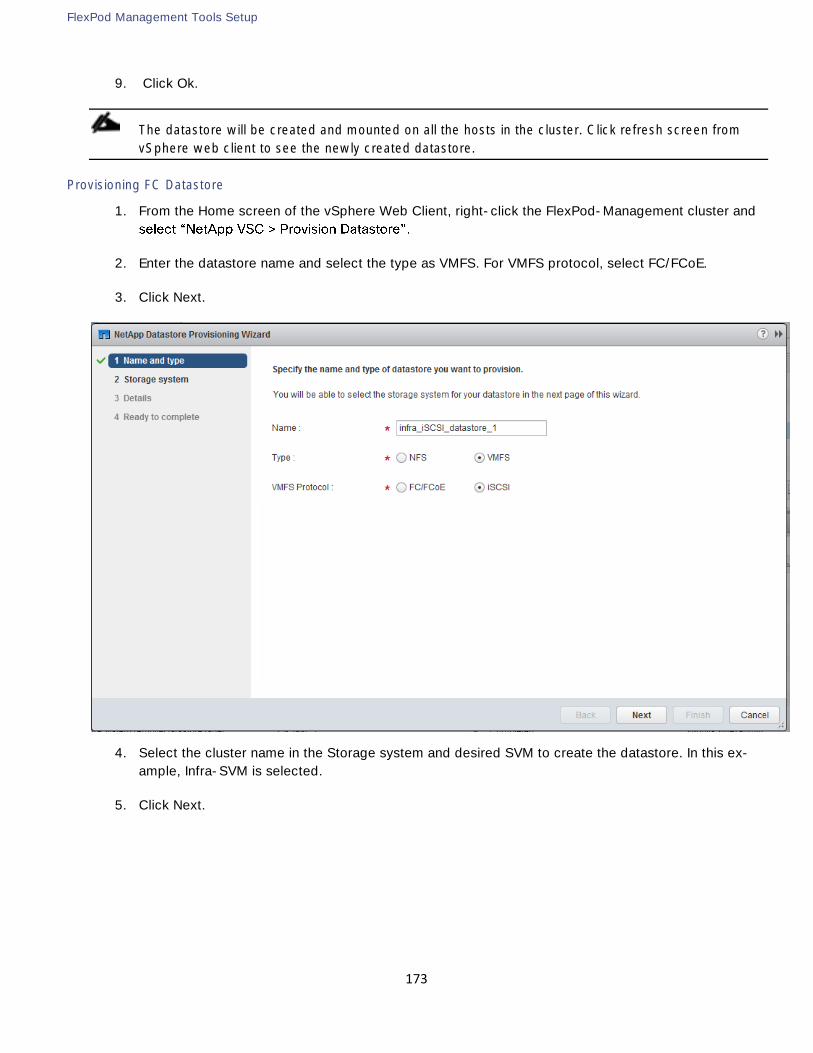
FlexPod Management Tools Setup
173
9. Click Ok.
The datastore will be created and mounted on all the hosts in the cluster. Click refresh screen from
vSphere web client to see the newly created datastore.
Provisioning FC Datastore
1. From the Home screen of the vSphere Web Client, right-click the FlexPod-Management cluster and
2. Enter the datastore name and select the type as VMFS. For VMFS protocol, select FC/FCoE.
3. Click Next.
4. Select the cluster name in the Storage system and desired SVM to create the datastore. In this ex-
ample, Infra-SVM is selected.
5. Click Next.

FlexPod Management Tools Setup
174
6. Enter the size of the datastore. Select box and select the aggregate
name.
7. Click Next.

FlexPod Management Tools Setup
175
8. Review the details and click Finish.
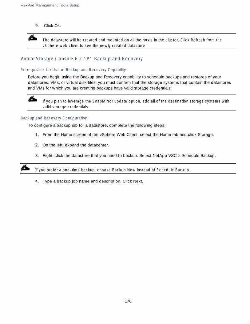
FlexPod Management Tools Setup
176
9. Click Ok.
The datastore will be created and mounted on all the hosts in the cluster. Click Refresh from the
vSphere web client to see the newly created datastore
Virtual Storage Console 6.2.1P1 Backup and Recovery
Prerequisites for Use of Backup and Recovery Capability
Before you begin using the Backup and Recovery capability to schedule backups and restores of your
datastores, VMs, or virtual disk files, you must confirm that the storage systems that contain the datastores
and VMs for which you are creating backups have valid storage credentials.
If you plan to leverage the SnapMirror update option, add all of the destination storage systems with
valid storage credentials.
Backup and Recovery Configuration
To configure a backup job for a datastore, complete the following steps:
1. From the Home screen of the vSphere Web Client, select the Home tab and click Storage.
2. On the left, expand the datacenter.
3. Right-click the datastore that you need to backup. Select NetApp VSC > Schedule Backup.
If you prefer a one-time backup, choose Backup Now instead of Schedule Backup.
4. Type a backup job name and description. Click Next.
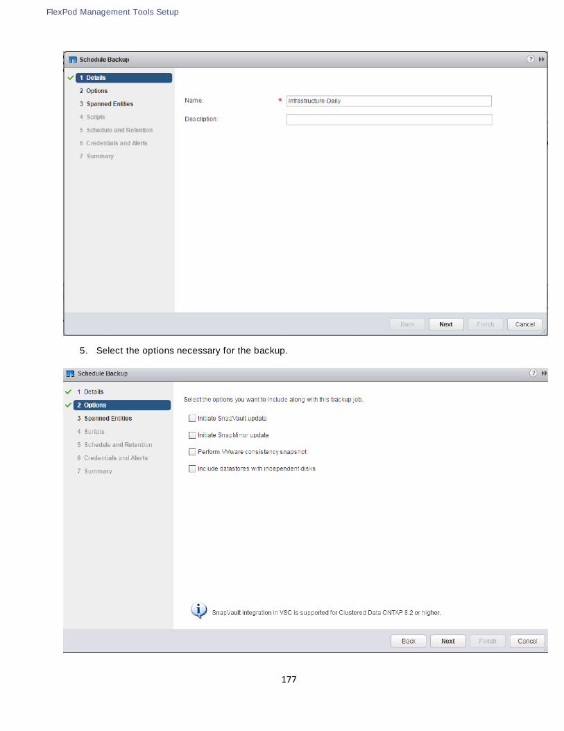
FlexPod Management Tools Setup
177
5. Select the options necessary for the backup.

FlexPod Management Tools Setup
178
For consistent VM snapshots, select Perform VMware Consistency Snapshot to make a VMware snap-
shot of each VM just before the NetApp Snapshot copy is made. The VMware snapshot is then deleted
after the NetApp Snapshot copy is made.
6. Click Next on the Options screen.
7. Click Next on the Spanned Entities screen.
8. Select one or more backup scripts if available, and click Next in the Scripts screen.
9. Select the hourly, daily, weekly, or monthly schedule and retention policy that you want for this back-
up job. Click Next.

FlexPod Management Tools Setup
179
10. Use the default vCenter credentials or enter the user name and password for the vCenter server.
Click Next.
11. Specify any needed backup notification details. Enter an e-mail address and mail server address for
receiving e-mail alerts. You can add multiple e-mail addresses by using semicolons to separate
them. Click Next.

FlexPod Management Tools Setup
180
12. Review the summary page and click Finish. If you want to run the job immediately, select the Run Job
Now option and then click Finish.
13. Click OK.
14. You can also create other backup jobs with overlapping schedules. For example, you can create
weekly or monthly backups that overlay daily backups.
15. On the storage cluster interface, automatic Snapshot copies of the volume can now be disabled be-
cause NetApp VSC is now handling scheduled backups. To do so, enter the following command:
volume modify -vserver Infra-SVM -volume infra_datastore_1 -snapshot-policy none
16. Also, to delete any existing automatic Snapshot copies that have been created on the volume, enter
the following command:
volume snapshot show -vserver Infra-SVM -volume infra_datastore_1
volume snapshot delete -vserver Infra-SVM -volume infra_datastore_1 -snapshot <snapshot-name>

FlexPod Management Tools Setup
181
The wildcard character * can be used in Snapshot names in the previous command.

Sample Tenant Provisioning
182
Sample Tenant Provisioning
Provisioning a Sample Application Tenant
This section describes a sample procedure for provisioning an application tenant. The procedure here refers
to previous sections of this document and can be used as a guide and modified as needed when
provisioning an application tenant.
1. Plan your application tenant and determine what storage protocols will be provided in the tenant. In
the architecture covered in this document, fiber channel, NFS, iSCSI, and CIFS/SMB can be provided
to the tenant. Also, plan what network VLANs the tenant will use. It is recommended to have a
VLAN for virtual machine management traffic. One or two VLANs (iSCSI needs two if VMware RDM
LUNs or iSCSI datastores will be provisioned) are also needed for each storage protocol used except
fiber channel. Fiber channel will have new storage LIFs defined with the same VSANs configured for
the FlexPod Infrastructure.
2. In the Nexus switches, declare all added VLANs and configure the VM VLAN as an allowed VLAN on
the UCS port channels and the vPC peer link. Also, Layer 3 with HSRP or VRRP can be configured in
the Nexus switches to provide this VLAN access to the outside. Layer 3 setup is not covered in this
document, but is covered in the Nexus 9000 documentation. Configure the storage VLANs on the
UCS and storage port channels, and on the vPC peer link. The VM VLAN can also be added to the
storage port channels in order to configure the tenant SVM management interface on this VLAN.
3. In the storage cluster:
Create a broadcast domain with MTU 1500 for the tenant SVM management interface. Create a.
a broadcast domain with MTU 9000 for each tenant storage protocol except fiber channel.
Create VLAN interface ports on the node interface group on each node for tenant SVM man-b.
agement (VM VLAN) and for the VLAN for each storage protocol except fiber channel. Add
these VLAN ports to the appropriate broadcast domains.
Create the tenant SVM and follow all procedures in that section. c.
Create Load-Sharing Mirrors for the tenant SVM. d.
Create the FC service for the tenant SVM if fiber channel is being deployed in this tenant. e.
Optionally, create a self-signed security certificate for the tenant SVM. f.
Configure NFSv3 for the tenant SVM. g.
Create a VM datastore volume in the tenant SVM. h.
Create a once-a-day deduplication schedule on the VM datastore volume. i.
If fiber channel is being deployed in this tenant, configure four FCP LIFs in the tenant SVM on j.
the same fiber channel ports as in the Infrastructure SVM.
Create an NFS LIF in the tenant SVM on each storage node. k.
Create a boot LUN in the esxi_boot volume in the Infra-SVM for each tenant VMware ESXi l.
host.

Sample Tenant Provisioning
183
Add the tenant SVM Administrator, SVM management LIF on the SVM management VLAN m.
port, and default route for the SVM.
4. In Cisco UCS, one method of tenant setup is to dedicate a VMware ESXi cluster and set of UCS
servers to each tenant. Service profiles will be generated for at least two tenant ESXi hosts. These
hosts can boot from LUNs from the esxi_boot volume in the Infra-SVM, but will also have access to
FC storage in the tenant SVM.
Create a Server Pool for the tenant ESXi host servers. a.
Create all tenant VLANs in the LAN Cloud. b.
Add the tenant VLANs to the DVS vNIC templates. c.
Generate service profiles from the service profile template with the vMedia policy for the tenant ESXi hosts.
Remember to bind these service profiles to the service profile template without the vMedia policy after
VMware ESXi installation.
In the Cisco MDS 9148S switches: 1.
Create device aliases for the tenant ESXi host vHBAs and the FC LIFs in the tenant storage a.
SVM.
Create zones for the tenant ESXi hosts with fiber channel targets from both the storage Infra-b.
SVM and the tenant SVM.
Add these zones to the Fabric zoneset and activate the zoneset. c.
In the storage cluster: 2.
Create igroups for the tenant ESXi hosts in both the Infra-SVM and tenant SVM. Also, create a.
an igroup in the tenant SVM that includes the WWPNs for all tenant ESXi hosts to support
shared storage from the tenant SVM.
In Infra-SVM, map the boot LUNs created earlier to the tenant ESXi hosts. Tenant FC storage b.
can be created later using either NetApp VSC or NetApp SnapDrive.
Install and configure VMware ESXi on all tenant host servers. It is not necessary to map in-3.
fra_datastore_1.
In VMware vCenter, create a cluster for the tenant ESXi hosts. Add the hosts to the cluster. 4.
Using the vCenter Web Client, add the tenant hosts to the VMware vDS. In the VMware vDS, add 5.
port-profiles for the tenant VLANs.
Back in vCenter, add in any necessary VMkernel ports for storage interfaces remembering to set the 6.
MTU correctly on these interfaces. Mount the tenant NFS datastore on the tenant cluster if one was
created.
Using the NetApp VSC plugin to the vCenter Web Client, set recommended values for all tenant ESXi 7.
hosts. Install the NetApp NFS Plug-in for VMware VAAI for all tenant hosts and reboot each host.
Optionally, create a VSC backup job for the tenant NFS datastore.
You can now begin provisioning virtual machines on the tenant cluster. The NetApp VSC plugin can 8.
be used to provision both fiber channel and NFS datastores.

Appendix
184
Appendix
Cisco UCS FCoE Direct Storage Connect Base Configuration
This FlexPod deployment will show configuration steps for both the Cisco UCS 6332-16UP and Cisco UCS
6248UP Fabric Interconnects (FI) in a design that will support Fibre Channel over Ethernet (FCoE)
connectivity to the NetApp.
Configuration steps will be referenced for both fabric interconnects and will be called out by the specific
model where steps have differed. Additionally, four FCoE LIFs are assumed to be created on the storage
controllers to be used by these fabric interconnects.
This section contains the Cisco UCS deployment with storage FCoE ports directly connected to the Cisco
UCS fabric interconnects. Fiber Channel (FC) direct connectivity is also supported but not covered in this
procedure.
The topology will circumvent the MDS within the FCoE direct storage connect configuration, connecting each
NetApp AFF A300 controller directly to each UCS Fabric Interconnect as shown in Figure 5 below.
Figure 5 FCoE Direct Connect FlexPod with Cisco UCS 6332-16UP Fabric Interconnects

Appendix
185
Cabling requirements are shown in Figure 6 below. The 6332-16UP cabling is shown, as with the topology
diagram previously shown, but in both cases the 6248UP can be swapped in with port changes adjusted as
appropriate.
Figure 6 FCoE Direct Connect FlexPod Cabling with Cisco UCS 6332-16UP Fabric Interconnect

Appendix
186
Perform Initial Setup of Cisco UCS 6332-16UP and 6248UP Fabric Interconnects for FlexPod
Environments
This section provides detailed procedures for configuring the Cisco Unified Computing System (Cisco UCS)
for use in a FlexPod environment. The steps are necessary to provision the Cisco UCS B-Series and C-
Series servers and should be followed precisely to avoid improper configuration.
Cisco UCS Fabric Interconnect A
To configure the Cisco UCS for use in a FlexPod environment, complete the following steps:
1. Connect to the console port on the first Cisco UCS fabric interconnect.
Enter the configuration method: gui
Physical switch Mgmt0 IP address: <ucsa-mgmt-ip>
Physical switch Mgmt0 IPv4 netmask: <ucsa-mgmt-mask>
IPv4 address of the default gateway: <ucsa-mgmt-gateway>
2. Using a supported web browser, connect to <https://ucsa-mgmt-ip>, accept the security prompts,
3. Select Initial Setup and click Submit.
4. Select Enable clustering, Fabric A, and IPv4.
5. Fill in the Virtual IP Address with the UCS cluster IP.
6. Completely fill in the System setup section. For system name, use the overall UCS system name. For
the Mgmt IP Address, use <ucsa-mgmt-ip>.
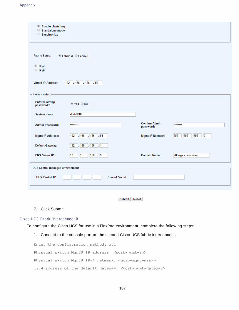
Appendix
187
7. Click Submit.
Cisco UCS Fabric Interconnect B
To configure the Cisco UCS for use in a FlexPod environment, complete the following steps:
1. Connect to the console port on the second Cisco UCS fabric interconnect.
Enter the configuration method: gui
Physical switch Mgmt0 IP address: <ucsb-mgmt-ip>
Physical switch Mgmt0 IPv4 netmask: <ucsb-mgmt-mask>
IPv4 address of the default gateway: <ucsb-mgmt-gateway>

Appendix
188
2. Using a supported web browser, connect to https://<ucsb-mgmt-ip>, accept the security prompts,
and click the
3. Under System setup, enter the Admin Password entered above and click Submit.
4. Enter <ucsb-mgmt-ip> for the Mgmt IP Address and click Submit.
Cisco UCS FCoE Direct Storage Connect Setup
Log in to Cisco UCS Manager
The steps are the same between the UCS 6332-16UP and the UCS 6248UP Fabric Interconnects un-
less otherwise noted
To log in to the Cisco Unified Computing System (UCS) environment, complete the following steps:
1. Open a web browser and navigate to the Cisco UCS fabric interconnect cluster address.
You may need to wait at least 5 minutes after configuring the second fabric interconnect for UCS Man-
ager to come up.
2. Click the Launch UCS Manager link under HTML to launch Cisco UCS Manager.
3. If prompted to accept security certificates, accept as necessary.
4. When prompted, enter admin as the user name and enter the administrative password.
5. Click Login to log in to Cisco UCS Manager.
Upgrade Cisco UCS Manager Software to Version 3.1(2f)
This document assumes the use of Cisco UCS 3.1(2f). To upgrade the Cisco UCS Manager software and the
Cisco UCS Fabric Interconnect software to version 3.1(2f), refer to Cisco UCS Manager Install and Upgrade
Guides.
Anonymous Reporting
To create anonymous reporting, complete the following step:
1. In the Anonymous Reporting window, select whether to send anonymous data to Cisco for improving
future products. If you select Yes, enter the IP address of your SMTP Server. Click OK.

Appendix
189
Configure Cisco UCS Call Home
It is highly recommended by Cisco to configure Call Home in Cisco UCS Manager. Configuring Call Home
will accelerate resolution of support cases. To configure Call Home, complete the following steps:
1. In Cisco UCS Manager, click Admin on the left.
2. Select All > Communication Management > Call Home.
3. Change the State to On.
4. Fill in all the fields according to your Management preferences and click Save Changes and OK to
complete configuring Call Home.
Place Cisco UCS Fabric Interconnects in Fiber Channel Switching Mode
In order to use FCOE Storage Ports for storage directly connected to the UCS fabric interconnects, the fabric
interconnects must be changed from fiber channel end host mode to fiber channel switching mode.
To place the fabric interconnects in fiber channel switching mode, complete the following steps:
1. In Cisco UCS Manager, click Equipment on the left.
2. Select Equipment > Fabric Interconnects > Fabric Interconnect A (primary).
3. In the center pane, select set FC Switching Mode. Click Yes and OK for the confirmation message.
4. Wait for both Fabric Interconnects to reboot by monitoring the console ports and log back into Cisco
UCS Manager.

Appendix
190
Add Block of IP Addresses for KVM Access
To create a block of IP addresses for in band server Keyboard, Video, Mouse (KVM) access in the Cisco UCS
environment, complete the following steps:
1. In Cisco UCS Manager, click LAN on the left.
2. Expand Pools > root > IP Pools.
3. Right-click IP Pool ext-mgmt and select Create Block of IPv4 Addresses.
4. Enter the starting IP address of the block, number of IP addresses required, and the subnet mask and
gateway information.
5. Click OK to create the block.
6. Click OK in the confirmation message.
Synchronize Cisco UCS to NTP
To synchronize the Cisco UCS environment to the NTP servers in the Nexus switches, complete the
following steps:
1. In Cisco UCS Manager, click Admin on the left.
2. Expand All > Time Zone Management.
3. Select Timezone.
4. In the Properties pane, select the appropriate time zone in the Time Zone pulldown.

Appendix
191
5. Click Save Changes, and then click OK.
6. Click Add NTP Server.
7. Enter <switch-a-ntp-ip> and click OK. Click OK on the confirmation.
8. Click Add NTP Server.
9. Enter <switch-b-ntp-ip> and click OK. Click OK on the confirmation.
Edit Chassis Discovery Policy
Setting the discovery policy simplifies the addition of B-Series Cisco UCS chassis and of additional fabric
extenders for further C-Series connectivity. To modify the chassis discovery policy, complete the following
steps:
1. In Cisco UCS Manager, click Equipment on the left and select Equipment in the second list.
2. In the right pane, click the Policies tab.
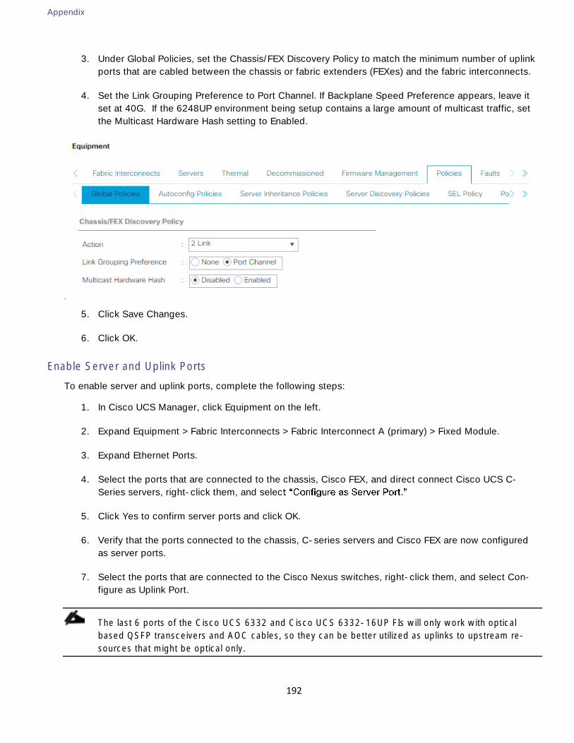
Appendix
192
3. Under Global Policies, set the Chassis/FEX Discovery Policy to match the minimum number of uplink
ports that are cabled between the chassis or fabric extenders (FEXes) and the fabric interconnects.
4. Set the Link Grouping Preference to Port Channel. If Backplane Speed Preference appears, leave it
set at 40G. If the 6248UP environment being setup contains a large amount of multicast traffic, set
the Multicast Hardware Hash setting to Enabled.
5. Click Save Changes.
6. Click OK.
Enable Server and Uplink Ports
To enable server and uplink ports, complete the following steps:
1. In Cisco UCS Manager, click Equipment on the left.
2. Expand Equipment > Fabric Interconnects > Fabric Interconnect A (primary) > Fixed Module.
3. Expand Ethernet Ports.
4. Select the ports that are connected to the chassis, Cisco FEX, and direct connect Cisco UCS C-
Series servers, right-click them, and selec
5. Click Yes to confirm server ports and click OK.
6. Verify that the ports connected to the chassis, C-series servers and Cisco FEX are now configured
as server ports.
7. Select the ports that are connected to the Cisco Nexus switches, right-click them, and select Con-
figure as Uplink Port.
The last 6 ports of the Cisco UCS 6332 and Cisco UCS 6332-16UP FIs will only work with optical
based QSFP transceivers and AOC cables, so they can be better utilized as uplinks to upstream re-
sources that might be optical only.

Appendix
193
8. Click Yes to confirm uplink ports and click OK.
9. Select the FCoE ports that are connected to the NetApp storage controllers, right-click them, and
select Configure as FCoE Storage Port.
10. Click Yes to confirm FCoE Storage ports and click OK.
11. Select Equipment > Fabric Interconnects > Fabric Interconnect B (subordinate) > Fixed Module.
12. Expand Ethernet Ports.
13. Select the ports that are connected to the chassis, C-series servers or to the Cisco 2232 FEX (two
per FEX), right-click them, and select Configure as Server Port.
14. Click Yes to confirm server ports and click OK.
15. Select the ports that are connected to the Cisco Nexus switches, right-click them, and select Con-
figure as Uplink Port.
16. Click Yes to confirm the uplink ports and click OK.
17. Select the FCoE ports that are connected to the NetApp storage controllers, right-click them, and
select Configure as FCoE Storage Port.
18. Click Yes to confirm FCoE Storage ports and click OK.
Acknowledge Cisco UCS Chassis and FEX
To acknowledge all Cisco UCS chassis and any external 2232 FEX modules, complete the following steps:
1. In Cisco UCS Manager, click Equipment on the left.
2. Expand Chassis and select each chassis that is listed.
3. Right-click each chassis and select Acknowledge Chassis.

Appendix
194
4. Click Yes and then click OK to complete acknowledging the chassis.
5. If Nexus 2232 FEX are part of the configuration, expand Rack Mounts and FEX.
6. Right-click each FEX that is listed and select Acknowledge FEX.
7. Click Yes and then click OK to complete acknowledging the FEX.
Create Uplink Port Channels to Cisco Nexus Switches
To configure the necessary port channels out of the Cisco UCS environment, complete the following steps:
1. In Cisco UCS Manager, click LAN on the left.
In this procedure, two port channels are created: one from fabric A to both Cisco Nexus switches and
one from fabric B to both Cisco Nexus switches.
2. Under LAN > LAN Cloud, expand the Fabric A tree.
3. Right-click Port Channels.
4. Select Create Port Channel.
5. Enter a unique ID of the port channel.
6. Enter vPC-Nexus as the name of the port channel.
7. Click Next.

Appendix
195
8. Select the ports connected to the Nexus switches to be added to the port channel:
9. Click >> to add the ports to the port channel.
10. Click Finish to create the port channel.
11. Click OK.
12. In the navigation pane, under LAN > LAN Cloud, expand the fabric B tree.
13. Right-click Port Channels.
14. Select Create Port Channel.
15. Enter a unique ID of the port channel.
16. Enter vPC-Nexus as the name of the port channel.
17. Click Next.
18. Select the ports connected to the Nexus switches to be added to the port channel:
19. Click >> to add the ports to the port channel.
20. Click Finish to create the port channel.
21. Click OK.
Create a WWNN Pool for FCoE Boot
To configure the necessary WWNN pool for the Cisco UCS environment, complete the following steps on
Cisco UCS Manager.
1. Select SAN on the left.
2. Select Pools > root.
3. Right-click WWNN Pools under the root organization.
4. Select Create WWNN Pool to create the WWNN pool.
5. Enter WWNN-Pool for the name of the WWNN pool.
6. Optional: Enter a description for the WWNN pool.
7. Select Sequential for Assignment Order.

Appendix
196
8. Click Next.
9. Click Add.
10. Modify the From field as necessary for the UCS Environment.
Modifications of the WWNN block, as well as the WWPN and MAC Addresses, can convey identifying
information for the UCS domain. Within the From field in our example, the 6th octet was changed from
00 to 48 to represent as identifying information for this being in the Cisco UCS 6248 in the 4th cabinet.
When there are multiple UCS domains sitting in adjacency, it is important that these blocks, the
WWNN, WWPN, and MAC hold differing values between each set.
11. Specify a size of the WWNN block sufficient to support the available server resources.

Appendix
197
12. Click OK.
13. Click Finish and OK to complete creating the WWNN pool.
Create WWPN Pools
To configure the necessary WWPN pools for the Cisco UCS environment, complete the following steps:
1. In Cisco UCS Manager, click SAN on the left.
2. Select Pools > root.
3. In this procedure, two WWPN pools are created, one for each switching fabric.
4. Right-click WWPN Pools under the root organization.
5. Select Create WWPN Pool to create the WWPN pool.
6. Enter WWPN-Pool-A as the name of the WWPN pool.
7. Optional: Enter a description for the WWPN pool.
8. Select Sequential for Assignment Order.
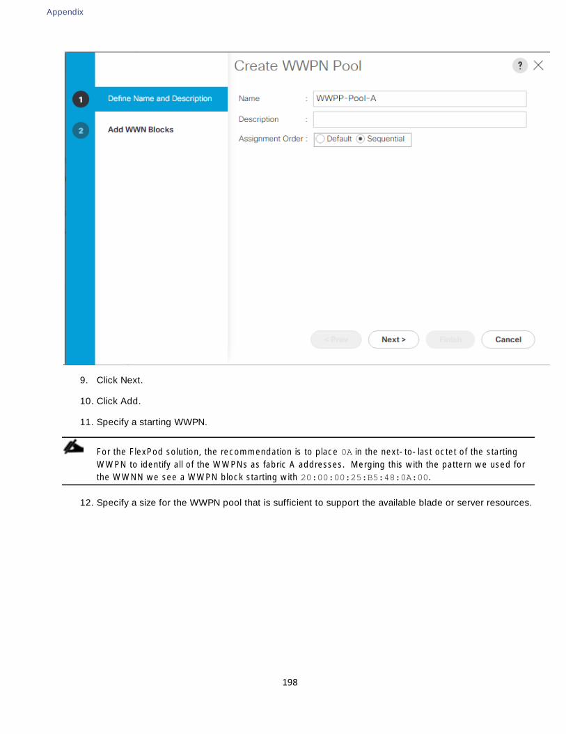
Appendix
198
9. Click Next.
10. Click Add.
11. Specify a starting WWPN.
For the FlexPod solution, the recommendation is to place 0A in the next-to-last octet of the starting
WWPN to identify all of the WWPNs as fabric A addresses. Merging this with the pattern we used for
the WWNN we see a WWPN block starting with 20:00:00:25:B5:48:0A:00.
12. Specify a size for the WWPN pool that is sufficient to support the available blade or server resources.

Appendix
199
13. Click OK.
14. Click Finish.
15. In the confirmation message, click OK.
16. Right-click WWPN Pools under the root organization.
17. Select Create WWPN Pool to create the WWPN pool.
18. Enter WWPN-Pool-B as the name of the WWPN pool.
19. Optional: Enter a description for the WWPN pool.
20. Select Sequential for Assignment Order.
21. Click Next.
22. Click Add.
23. Specify a starting WWPN.
For the FlexPod solution, the recommendation is to place 0B in the next-to-last octet of the starting
WWPN to identify all of the WWPNs as fabric A addresses. Merging this with the pattern we used for
the WWNN we see a WWPN block starting with 20:00:00:25:B5:48:0B:00.

Appendix
200
24. Specify a size for the WWPN address pool that is sufficient to support the available blade or server
resources.
25. Click OK.
26. Click Finish.
27. In the confirmation message, click OK.
Create Storage VSANs
To configure the necessary virtual storage area networks (VSANs) for the Cisco UCS environment, complete
the following steps:
1. In Cisco UCS Manager, click SAN on the left.
In this procedure, two VSANs are created.
2. Select SAN > Storage Cloud.
3. Right-click VSANs.
4. Select Create Storage VSAN.
5. Enter VSAN-A as the name of the VSAN to be used for Fabric A
6. Set FC Zoning to Enabled.
7. Select Fabric A.
8. Enter a unique VSAN ID and a corresponding FCoE VLAN ID for Fabric A. It is recommended to use
the same ID for both parameters and to use something other than 1.

Appendix
201
9. Click OK and then click OK again.
10. Under Storage Cloud, right-click VSANs.
11. Select Create Storage VSAN.
12. Enter VSAN-B as the name of the VSAN to be used for Fabric B.
13. Set FC Zoning to Enabled.
14. Select Fabric B.
15. Enter a unique VSAN ID and a corresponding FCoE VLAN ID for Fabric B. It is recommended use the
same ID for both parameters and to use something other than 1.

Appendix
202
16. Click OK and then click OK again.
Assign VSANs to FCoE Storage Ports
To assign storage VSANs to FCoE Storage Ports, complete the following steps:
1. In Cisco UCS Manager, click SAN on the left.
2. Select SAN > Storage Cloud.
3. Expand Fabric A and Storage FCoE Interfaces.
4. Select the first FCoE Interface.
5. For User Label, enter the storage controller name and port. Click Save Changes and OK.
6. Use the pulldown to select VSAN VSAN-A. Click Save Changes and OK.

Appendix
203
7. Select the second FCoE Interface.
8. For User Label, enter the storage controller name and port. Click Save Changes and OK.
9. Use the pulldown to select VSAN VSAN-A. Click Save Changes and OK.
10. Expand Fabric B and Storage FCoE Interfaces.
11. Select the first FCoE Interface.
12. For User Label, enter the storage controller name and port. Click Save Changes and OK.
13. Use the pulldown to select VSAN VSAN-B. Click Save Changes and OK.
14. Select the second FCoE Interface.
15. For User Label, enter the storage controller name and port. Click Save Changes and OK.
16. Use the pulldown to select VSAN VSAN-B. Click Save Changes and OK.
Create vHBA Templates
To create the necessary virtual host bus adapter (vHBA) templates for the Cisco UCS environment, complete
the following steps:
1. In Cisco UCS Manager, click SAN on the left.
2. Select Policies > root.
3. Right-click vHBA Templates.
4. Select Create vHBA Template.
5. Enter vHBA-Template-A as the vHBA template name.
6. Keep Fabric A selected.

Appendix
204
7. Leave Redundancy Type set to No Redundancy.
8. Select VSAN-A.
9. Leave Initial Template as the Template Type.
10. Select WWPN-Pool-A as the WWPN Pool.
11. Click OK to create the vHBA template.
12. Click OK.
13. Right-click vHBA Templates.
14. Select Create vHBA Template.

Appendix
205
15. Enter vHBA-Template-B as the vHBA template name.
16. Leave Redundancy Type set to No Redundancy.
17. Select Fabric B as the Fabric ID.
18. Select VSAN-B.
19. Leave Initial Template as the Template Type.
20. Select WWPN-Pool-B as the WWPN Pool.
21. Click OK to create the vHBA template.
22. Click OK.
Create SAN Connectivity Policy
To configure the necessary Infrastructure SAN Connectivity Policy, complete the following steps:
1. In Cisco UCS Manager, click SAN on the left.
2. Select SAN > Policies > root.
3. Right-click SAN Connectivity Policies.
4. Select Create SAN Connectivity Policy.
5. Enter FC-Boot as the name of the policy.
6. Select the previously created WWNN-Pool for the WWNN Assignment.
7. Click the Add button at the bottom to add a vHBA.
8. In the Create vHBA dialog box, enter Fabric-A as the name of the vHBA.
9. Select the Use vHBA Template checkbox.
10. In the vHBA Template list, select vHBA-Template-A.
11. In the Adapter Policy list, select VMWare.
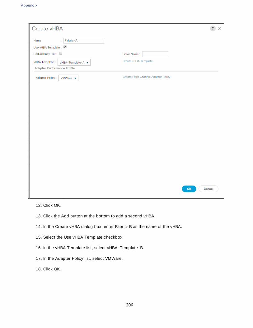
Appendix
206
12. Click OK.
13. Click the Add button at the bottom to add a second vHBA.
14. In the Create vHBA dialog box, enter Fabric-B as the name of the vHBA.
15. Select the Use vHBA Template checkbox.
16. In the vHBA Template list, select vHBA-Template-B.
17. In the Adapter Policy list, select VMWare.
18. Click OK.

Appendix
207
19. Click OK to create the SAN Connectivity Policy.
20. Click OK to confirm creation.
Create MAC Address Pools
To configure the necessary MAC address pools for the Cisco UCS environment, complete the following
steps:
1. In Cisco UCS Manager, click LAN on the left.
2. Select Pools > root.
In this procedure, two MAC address pools are created, one for each switching fabric.

Appendix
208
3. Right-click MAC Pools under the root organization.
4. Select Create MAC Pool to create the MAC address pool.
5. Enter MAC-Pool-A as the name of the MAC pool.
6. Optional: Enter a description for the MAC pool.
7. Select Sequential as the option for Assignment Order.
8. Click Next.
9. Click Add.
10. Specify a starting MAC address.
For the FlexPod solution, the recommendation is to place 0A in the next-to-last octet of the starting
MAC address to identify all of the MAC addresses as fabric A addresses. In our example, we have
carried forward the of also embedding the UCS domain number information giving us
00:25:B5:48:0A:00 as our first MAC address.
11. Specify a size for the MAC address pool that is sufficient to support the available blade or server re-
sources, noting that 6 virtual network interfaces (vNICs) will be created on each server.

Appendix
209
12. Click OK.
13. Click Finish.
14. In the confirmation message, click OK.
15. Right-click MAC Pools under the root organization.
16. Select Create MAC Pool to create the MAC address pool.
17. Enter MAC-Pool-B as the name of the MAC pool.
18. Optional: Enter a description for the MAC pool.
19. Select Sequential as the option for Assignment Order.
20. Click Next.
21. Click Add.

Appendix
210
22. Specify a starting MAC address.
For the FlexPod solution, it is recommended to place 0B in the next to last octet of the starting MAC
address to identify all the MAC addresses in this pool as fabric B addresses. Once again, we have
carried forward in our example of also embedding the UCS domain number information giving us
00:25:B5:48:0B:00 as our first MAC address.
23. Specify a size for the MAC address pool that is sufficient to support the available blade or server re-
sources.
24. Click OK.
25. Click Finish.
26. In the confirmation message, click OK.
Create UUID Suffix Pool
To configure the necessary universally unique identifier (UUID) suffix pool for the Cisco UCS environment,
complete the following steps:
1. In Cisco UCS Manager, click Servers on the left.
2. Select Pools > root.
3. Right-click UUID Suffix Pools.
4. Select Create UUID Suffix Pool.
5. Enter UUID-Pool as the name of the UUID suffix pool.
6. Optional: Enter a description for the UUID suffix pool.
7. Keep the prefix at the derived option.
8. Select Sequential for the Assignment Order.
9. Click Next.
10. Click Add to add a block of UUIDs.
11. Keep the From field at the default setting.
12. Specify a size for the UUID block that is sufficient to support the available blade or server resources.
13. Click OK.
14. Click Finish.
15. Click OK.

Appendix
211
Create Server Pool
To configure the necessary server pool for the Cisco UCS environment, complete the following steps:
Consider creating unique server pools to achieve the granularity that is required in your environment.
1. In Cisco UCS Manager, click Servers on the left.
2. Select Pools > root.
3. Right-click Server Pools.
4. Select Create Server Pool.
5. Enter Infra-Pool as the name of the server pool.
6. Optional: Enter a description for the server pool.
7. Click Next.
8. Select two (or more) servers to be used for the VMware management cluster and click >> to add
them to the Infra-Pool server pool.
9. Click Finish.
10. Click OK.
Create VLANs
To configure the necessary virtual local area networks (VLANs) for the Cisco UCS environment, complete the
following steps:
1. In Cisco UCS Manager, click LAN on the left.
In this procedure, five unique VLANs are created. See Table 2
2. Select LAN > LAN Cloud.
3. Right-click VLANs.
4. Select Create VLANs.
5. Enter Native-VLAN as the name of the VLAN to be used as the native VLAN.
6. Keep the Common/Global option selected for the scope of the VLAN.
7. Enter the native VLAN ID.
8. Keep the Sharing Type as None.

Appendix
212
9. Click OK, and then click OK again.
10. Expand the list of VLANs in the navigation pane, right-click the newly created Native-VLAN and se-
lect Set as Native VLAN.
11. Click Yes and then click OK.
12. Right-click VLANs.
13. Select Create VLANs
14. Enter IB-MGMT as the name of the VLAN to be used for management traffic.
15. Keep the Common/Global option selected for the scope of the VLAN.
16. Enter the In-Band management VLAN ID.
17. Keep the Sharing Type as None.
18. Click OK, and then click OK again.
19. Right-click VLANs.

Appendix
213
20. Select Create VLANs.
21. Enter Infra-NFS as the name of the VLAN to be used for NFS.
22. Keep the Common/Global option selected for the scope of the VLAN.
23. Enter the Infrastructure NFS VLAN ID.
24. Keep the Sharing Type as None.
25. Click OK, and then click OK again.
26. Right-click VLANs.
27. Select Create VLANs.
28. Enter vMotion as the name of the VLAN to be used for vMotion.
29. Keep the Common/Global option selected for the scope of the VLAN.
30. Enter the vMotion VLAN ID.
31. Keep the Sharing Type as None.
32. Click OK, and then click OK again.
33. Right-click VLANs.
34. Select Create VLANs.
35. Enter VM-Traffic as the name of the VLAN to be used for VM Traffic.
36. Keep the Common/Global option selected for the scope of the VLAN.
37. Enter the VM-Traffic VLAN ID.
38. Keep the Sharing Type as None.
39. Click OK and then click OK again.

Appendix
214
Modify Default Host Firmware Package
Firmware management policies allow the administrator to select the corresponding packages for a given
server configuration. These policies often include packages for adapter, BIOS, board controller, FC adapters,
host bus adapter (HBA) option ROM, and storage controller properties.
To create a firmware management policy for a given server configuration in the Cisco UCS environment,
complete the following steps:
1. In Cisco UCS Manager, click Servers on the left.
2. Select Policies > root.
3. Expand Host Firmware Packages.
4. Select default.
5. In the Actions pane, select Modify Package Versions.
6. Select the version 3.1(2f) for both the Blade and Rack Packages.
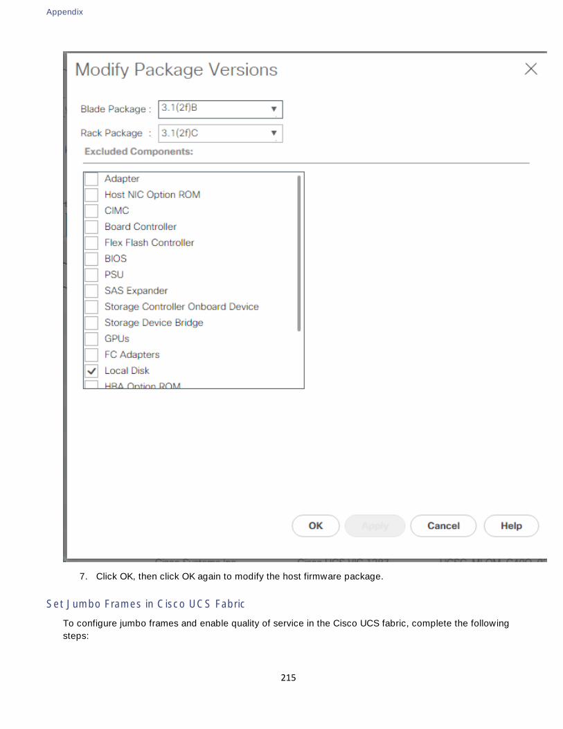
Appendix
215
7. Click OK, then click OK again to modify the host firmware package.
Set Jumbo Frames in Cisco UCS Fabric
To configure jumbo frames and enable quality of service in the Cisco UCS fabric, complete the following
steps:
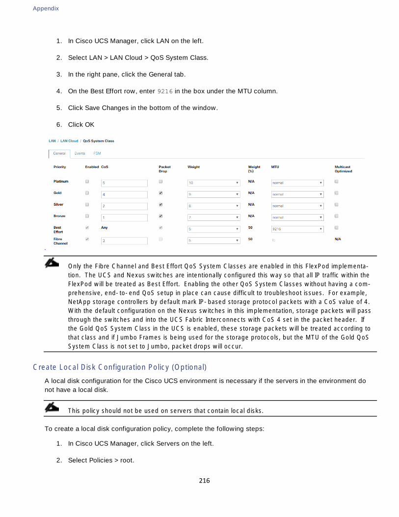
Appendix
216
1. In Cisco UCS Manager, click LAN on the left.
2. Select LAN > LAN Cloud > QoS System Class.
3. In the right pane, click the General tab.
4. On the Best Effort row, enter 9216 in the box under the MTU column.
5. Click Save Changes in the bottom of the window.
6. Click OK
Only the Fibre Channel and Best Effort QoS System Classes are enabled in this FlexPod implementa-
tion. The UCS and Nexus switches are intentionally configured this way so that all IP traffic within the
FlexPod will be treated as Best Effort. Enabling the other QoS System Classes without having a com-
prehensive, end-to-end QoS setup in place can cause difficult to troubleshoot issues. For example,
NetApp storage controllers by default mark IP-based storage protocol packets with a CoS value of 4.
With the default configuration on the Nexus switches in this implementation, storage packets will pass
through the switches and into the UCS Fabric Interconnects with CoS 4 set in the packet header. If
the Gold QoS System Class in the UCS is enabled, these storage packets will be treated according to
that class and if Jumbo Frames is being used for the storage protocols, but the MTU of the Gold QoS
System Class is not set to Jumbo, packet drops will occur.
Create Local Disk Configuration Policy (Optional)
A local disk configuration for the Cisco UCS environment is necessary if the servers in the environment do
not have a local disk.
This policy should not be used on servers that contain local disks.
To create a local disk configuration policy, complete the following steps:
1. In Cisco UCS Manager, click Servers on the left.
2. Select Policies > root.

Appendix
217
3. Right-click Local Disk Config Policies.
4. Select Create Local Disk Configuration Policy.
5. Enter SAN-Boot as the local disk configuration policy name.
6. Change the mode to No Local Storage.
7. Click OK to create the local disk configuration policy.

Appendix
218
8. Click OK.
Create Network Control Policy for Cisco Discovery Protocol (CDP) and Link Layer Discovery
Protocol (LLDP)
To create a network control policy that enables CDP and LLDP on virtual network ports, complete the
following steps:

Appendix
219
1. In Cisco UCS Manager, click LAN on the left.
2. Select Policies > root.
3. Right-click Network Control Policies.
4. Select Create Network Control Policy.
5. Enter Enable-CDP-LLDP as the policy name.
6. For CDP, select the Enabled option.
7. For LLDP, scroll down and select Enabled for both Transmit and Receive.
8. Click OK to create the network control policy.
9. Click OK.
Create Power Control Policy
To create a power control policy for the Cisco UCS environment, complete the following steps:
1. In Cisco UCS Manager, click Servers tab on the left.
2. Select Policies > root.

Appendix
220
3. Right-click Power Control Policies.
4. Select Create Power Control Policy.
5. Enter No-Power-Cap as the power control policy name.
6. Change the power capping setting to No Cap.
7. Click OK to create the power control policy.
8. Click OK.
Create Server Pool Qualification Policy (Optional)
To create an optional server pool qualification policy for the Cisco UCS environment, complete the following
steps:

Appendix
221
This example creates a policy for Cisco UCS B-Series and Cisco UCS C-Series servers with the Intel
E2660 v4 Xeon Broadwell processors.
1. In Cisco UCS Manager, click Servers on the left.
2. Select Policies > root.
3. Right-click Server Pool Policy Qualifications.
4. Select Create Server Pool Policy Qualification.
5. Name the policy UCS-Broadwell.
6. Select Create CPU/Cores Qualifications.
7. Select Xeon for the Processor/Architecture.
8. Select UCS-CPU-E52660E as the PID.
9. Click OK to create the CPU/Core qualification.
10. Click OK to create the policy then OK for the confirmation.

Appendix
222
Create Server BIOS Policy
To create a server BIOS policy for the Cisco UCS environment, complete the following steps:
1. In Cisco UCS Manager, click Servers on the left.
2. Select Policies > root.
3. Right-click BIOS Policies.
4. Select Create BIOS Policy.
5. Enter VM-Host as the BIOS policy name.
6. Change the Quiet Boot setting to disabled.
7. Change Consistent Device Naming to enabled.
8. Click the Processor tab on the left.
9. Set the following within the Processor tab:
Processor C State -> disabled a.
Processor C1E -> disabled b.

Appendix
223
Processor C3 Report -> disabled c.
Processor C7 Report -> disabled d.
10. Scroll down to the remaining Processor options, and select:
Energy Performance -> performance a.
Frequency Floor Override -> enabled b.
DRAM Clock Throttling -> performance c.

Appendix
224
11. Click the RAS Memory option and select:
LV DDR Mode -> performance-mode a.
12. Click Finish to create the BIOS policy.
13. Click OK.
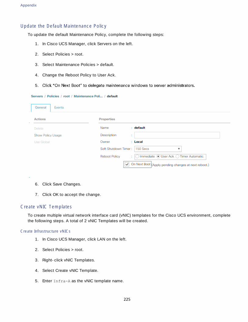
Appendix
225
Update the Default Maintenance Policy
To update the default Maintenance Policy, complete the following steps:
1. In Cisco UCS Manager, click Servers on the left.
2. Select Policies > root.
3. Select Maintenance Policies > default.
4. Change the Reboot Policy to User Ack.
5.
6. Click Save Changes.
7. Click OK to accept the change.
Create vNIC Templates
To create multiple virtual network interface card (vNIC) templates for the Cisco UCS environment, complete
the following steps. A total of 2 vNIC Templates will be created.
Create Infrastructure vNICs
1. In Cisco UCS Manager, click LAN on the left.
2. Select Policies > root.
3. Right-click vNIC Templates.
4. Select Create vNIC Template.
5. Enter Infra-A as the vNIC template name.

Appendix
226
6. Keep Fabric A selected.
7. Select the Enable Failover checkbox.
Selecting Failover is a critical step to improve link failover time by handling it at the hardware level, and
to guard against NIC any potential for NIC failure not being detected by the virtual switch.
8. Select Primary Template for Redundancy Type.
9. Leave the Peer Redundancy Template set to <not set>.
10. Under Target, make sure that only the Adapter checkbox is selected.
11. Select Updating Template as the Template Type.
12. Under VLANs, select the checkboxes for IB-MGMT, Infra-NFS, vMotion VM-Traffic, and Native-
VLAN VLANs.
13. Set Native-VLAN as the native VLAN.
14. Select vNIC Name for the CDN Source.
15. For MTU, enter 9000.
16. In the MAC Pool list, select MAC-Pool-A.
17. In the Network Control Policy list, select Enable-CDP-LLDP.

Appendix
227
18. Click OK to create the vNIC template.
19. Click OK.
Create the secondary redundancy template Infra-B:
1. Select LAN on the left.
2. Select Policies > root.
3. Right-click vNIC Templates.
Appendix
228
4. Select Create vNIC Template
5. Enter Infra-B as the vNIC template name.
6. Select Fabric B.
7. Select the Enable Failover checkbox.
8. Set Redundancy Type to Secondary Template.
9. Select Infra-A for the Peer Redundancy Template.
10. In the MAC Pool list, select MAC-Pool-B. The MAC Pool is all that needs to be selected for the Sec-
ondary Template.
11. Click OK to create the vNIC template.
12. Click OK.
Create LAN Connectivity Policy for FC Boot
To configure the necessary Infrastructure LAN Connectivity Policy, complete the following steps:
1. In Cisco UCS Manager, click LAN on the left.
2. Select LAN > Policies > root.
3. Right-click LAN Connectivity Policies.
4. Select Create LAN Connectivity Policy.
5. Enter FC-Boot as the name of the policy.
6. Click the upper Add button to add a vNIC.
7. In the Create vNIC dialog box, enter 00-Infra-A as the name of the vNIC.
8. Select the Use vNIC Template checkbox.
9. In the vNIC Template list, select Infra-A.
10. In the Adapter Policy list, select VMWare.
11. Click OK to add this vNIC to the policy.

Appendix
229
12. Click the upper Add button to add another vNIC to the policy.
13. In the Create vNIC box, enter 01-Infra-B as the name of the vNIC.
14. Select the Use vNIC Template checkbox.
15. In the vNIC Template list, select Infra-B.
16. In the Adapter Policy list, select VMWare.
17. Click OK to add the vNIC to the policy.

Appendix
230
18. Click OK, then click OK again to create the LAN Connectivity Policy.
Create vMedia Policy for VMware ESXi 6.5a Install Boot
In the NetApp ONTAP setup steps an HTTP web server is required, which will be used for hosting ONTAP as
well as VMware software. The vMedia Policy created here will map the VMware ESXi 6.5a ISO to the Cisco
UCS server in order to boot the ESXi installation. To create this policy, complete the following steps:
1. In Cisco UCS Manager, select Servers on the left.
2. Select Policies > root.
3. Right-click vMedia Policies.
4. Select Create vMedia Policy.

Appendix
231
5. Name the policy ESXi-6.5a-HTTP.
6. Mounts ISO for ESXi 6.5a
7. Click Add.
8. Name the mount ESXi-6.5a-HTTP.
9. Select the CDD Device Type.
10. Select the HTTP Protocol.
11. Enter the IP Address of the web server.
Since DNS server IPs were not entered into the KVM IP earlier, it is necessary to enter the IP of the
web server instead of the hostname.
12. Enter VMware-VMvisor-Installer-201701001-4887370.x86_64.iso as the Remote File name.
This VMware ESXi 6.5a ISO can be downloaded from VMware Downloads.
13. Enter the web server path to the ISO file in the Remote Path field.

Appendix
232
14. Click OK to create the vMedia Mount.
15. Click OK then OK again to complete creating the vMedia Policy.
For any new servers added to the Cisco UCS environment the vMedia service profile template can be
used to install the ESXi host. On first boot the host will boot into the ESXi installer since the SAN
mounted disk is empty. After ESXi is installed, the vMedia will not be referenced as long as the boot
disk is accessible.
Create Boot Policy (FCoE Boot)
This procedure applies to a Cisco UCS environment in which two FCoE logical interfaces (LIFs) are on cluster
node 1 and two FCoE LIFs are on cluster node 2 for each Cisco UCS Fabric Interconnect:
To create a boot policy for the Cisco UCS environment, complete the following steps:
1. In Cisco UCS Manager, click Servers on the left.
2. Select Policies > root.
3. Right-click Boot Policies.

Appendix
233
4. Select Create Boot Policy.
5. Enter Boot-FC-Fabric-A as the name of the boot policy.
6. Optional: Enter a description for the boot policy.
Do not select the Reboot on Boot Order Change checkbox.
7. Keep the Reboot on Boot Order Change option cleared.
8. Expand the Local Devices drop-down menu and select Add Remote CD/DVD.
9. Expand the vHBAs drop-down menu and select Add SAN Boot.
10. Select the Primary Type.
11. Enter Fabric-A in the vHBA field.
12. Confirm that Primary is selected for the Type option.
13. Click OK to add the SAN boot initiator.
14. From the vHBA drop-down menu, select Add SAN Boot Target.
15. Keep 0 as the value for Boot Target LUN.
16. Enter the WWPN for fcp_lif01a.
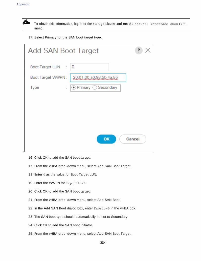
Appendix
234
To obtain this information, log in to the storage cluster and run the network interface show com-
mand.
17. Select Primary for the SAN boot target type.
16. Click OK to add the SAN boot target.
17. From the vHBA drop-down menu, select Add SAN Boot Target.
18. Enter 0 as the value for Boot Target LUN.
19. Enter the WWPN for fcp_lif02a.
20. Click OK to add the SAN boot target.
21. From the vHBA drop-down menu, select Add SAN Boot.
22. In the Add SAN Boot dialog box, enter Fabric-B in the vHBA box.
23. The SAN boot type should automatically be set to Secondary.
24. Click OK to add the SAN boot initiator.
25. From the vHBA drop-down menu, select Add SAN Boot Target.
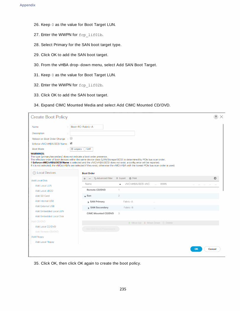
Appendix
235
26. Keep 0 as the value for Boot Target LUN.
27. Enter the WWPN for fcp_lif01b.
28. Select Primary for the SAN boot target type.
29. Click OK to add the SAN boot target.
30. From the vHBA drop-down menu, select Add SAN Boot Target.
31. Keep 0 as the value for Boot Target LUN.
32. Enter the WWPN for fcp_lif02b.
33. Click OK to add the SAN boot target.
34. Expand CIMC Mounted Media and select Add CIMC Mounted CD/DVD.
35. Click OK, then click OK again to create the boot policy.
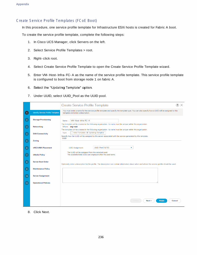
Appendix
236
Create Service Profile Templates (FCoE Boot)
In this procedure, one service profile template for Infrastructure ESXi hosts is created for Fabric A boot.
To create the service profile template, complete the following steps:
1. In Cisco UCS Manager, click Servers on the left.
2. Select Service Profile Templates > root.
3. Right-click root.
4. Select Create Service Profile Template to open the Create Service Profile Template wizard.
5. Enter VM-Host-Infra-FC-A as the name of the service profile template. This service profile template
is configured to boot from storage node 1 on fabric A.
6.
7. Under UUID, select UUID_Pool as the UUID pool.
8. Click Next.
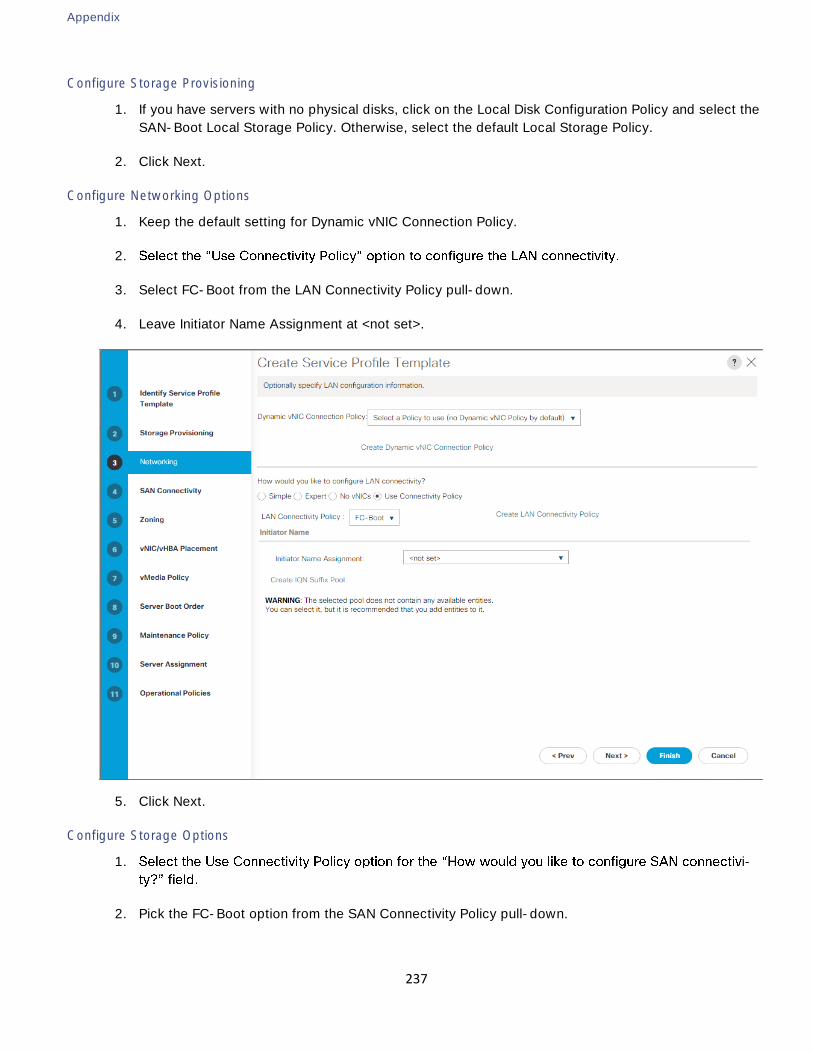
Appendix
237
Configure Storage Provisioning
1. If you have servers with no physical disks, click on the Local Disk Configuration Policy and select the
SAN-Boot Local Storage Policy. Otherwise, select the default Local Storage Policy.
2. Click Next.
Configure Networking Options
1. Keep the default setting for Dynamic vNIC Connection Policy.
2.
3. Select FC-Boot from the LAN Connectivity Policy pull-down.
4. Leave Initiator Name Assignment at <not set>.
5. Click Next.
Configure Storage Options
1. i-
2. Pick the FC-Boot option from the SAN Connectivity Policy pull-down.

Appendix
238
3. Click Next.
Configure Zoning Options
1. Set no Zoning options and click Next.
Configure vNIC/HBA Placement
1.
2. Click Next.
Configure vMedia Policy
1. Do not select a vMedia Policy.
2. Click Next.
Configure Server Boot Order
1. Select Boot-FC-Fabric-A for Boot Policy.

Appendix
239
2. Click Next to continue to the next section.
Configure Maintenance Policy
1. Change the Maintenance Policy to default.

Appendix
240
2. Click Next.
Configure Server Assignment
To configure server assignment, complete the following steps:
1. In the Pool Assignment list, select Infra-Pool.
3. Select Down as the power state to be applied when the profile is associated with the server.
4. -
5. Expand Firmware Management at the bottom of the page and select the default policy.

Appendix
241
6. Click Next.
Configure Operational Policies
To configure the operational policies, complete the following steps:
1. In the BIOS Policy list, select VM-Host.
2. Expand Power Control Policy Configuration and select No-Power-Cap in the Power Control Policy
list.

Appendix
242
3. Click Finish to create the service profile template.
4. Click OK in the confirmation message.
Create vMedia Service Profile Template
To create service profiles from the service profile template, complete the following steps:
1. Connect to UCS Manager, click Servers on the left.
2. Select Service Profile Templates > root > Service Template VM-Host-Infra-FC-A.
3. Right-click Service Template VM-Host-Infra-FC-A and select Create a Clone.
4. Name the clone VM-Host-Infra-FC-A-vM and click OK.
5. Select Service Template VM-Host-Infra-FC-A-vM.
6. In the right pane, select the vMedia Policy tab.
7. Under Actions, select Modify vMedia Policy.
8. Using the pulldown, select the ESXi-6.0U2-HTTP vMedia Policy.

Appendix
243
9. Click OK then OK again to complete modifying the Service Profile Template.
Create Service Profiles
To create service profiles from the service profile template, complete the following steps:
1. Connect to UCS Manager, click Servers on the left.
2. Select Service Profile Templates > root > Service Template VM-Host-Infra-FC-A-vM.
3. Right-click VM-Host-Infra-FC-A-vM and select Create Service Profiles from Template.
4. Enter VM-Host-Infra-0 as the service profile prefix.
5.
6.
7. Click OK to create the service profiles.
8. Click OK in the confirmation message.
Add More Servers to FlexPod Unit
Additional server pools, service profile templates, and service profiles can be created in the respective
organizations to add more servers to the FlexPod unit. All other pools and policies are at the root level and
can be shared among the organizations.

Appendix
244
Gather Necessary Information
After the Cisco UCS service profiles have been created, each infrastructure server in the environment will
have a unique configuration. To proceed with the FlexPod deployment, specific information must be
gathered from each Cisco UCS server and from the NetApp controllers. Insert the required information into
Table 8 and Table 9 .
Table 8 WWPNs from NetApp Storage
SVM Target LIF WWPN (FC)
Infra-SVM fcp_lif01a
fcp_lif01b
fcp_lif02a
fcp_lif02b
To obtain the FC WWPNs, run the network interface show command on the storage cluster manage-
ment interface.
Table 9 FC WWPNs for Fabric A and Fabric B
Cisco UCS Service Profile Name Initiator: WWPNs (FC) Variables
VM-Host-Infra-01 <vm-host-infra-01-wwpna>
<vm-host-infra-01-wwpnb>
VM-Host-Infra-02 <vm-host-infra-02-wwpna>
<vm-host-infra-02-wwpnb>
To obtain the FC vHBA WWPN information in Cisco UCS Manager GUI, go to Servers > Service Profiles >
root. Click each service profile and then click the “Storage” tab, then “vHBAs” tab on the right. The WWPNs
are displayed in the table at the bottom of the page.
Adding Direct Connected Tenant FCoE Storage
To add FCoE storage from an additional storage SVM, two storage connection policies, one for each fabric
must be added in Cisco UCS Manager and attached to vHBA Initiator Groups in the SAN Connectivity Policy.
These steps were not shown in the initial deployment above because it is not necessary to zone boot
targets. Boot targets are automatically zoned in the fabric interconnect when zoning is enabled on the fabric
VSAN. To add direct connected tenant FCoE storage from a tenant SVM, complete the following steps:
Create Storage Connection Policies
In this procedure, one storage connection policy is created for each fabric.
To create the storage connection policies, complete the following steps:

Appendix
245
1. In Cisco UCS Manager, click SAN on the left.
2. Right-click SAN > Policies > root > Storage Connection Policies and select Create Storage Connec-
tion Policy.
3. Name the policy to indicate a tenant on Fabric A.
4. Select the Single Initiator Multiple Targets Zoning Type.
5. Click Add to add a target.
6. Enter the WWPN of the first fabric A FCoE LIF in the tenant SVM connected to fabric interconnect A.
Select Path A and VSAN VSAN-A. Click OK.
7. Click Add to add a target.
8. Enter the WWPN of the second fabric A FCoE LIF in the tenant SVM connected to fabric interconnect
A. Select Path A and VSAN VSAN-A. Click OK.
9. Click OK then click OK again to complete adding the Storage Connection Policy.
10. Right-click SAN > Policies > root > Storage Connection Policies and select Create Storage Connec-
tion Policy.
11. Name the policy to indicate a tenant on Fabric B.
12. Select the Single Initiator Multiple Targets Zoning Type.
13. Click Add to add a target.
14. Enter the WWPN of the first fabric B FCoE LIF in the tenant SVM connected to fabric interconnect B.
Select Path B and VSAN VSAN-B. Click OK.
15. Click Add to add a target.
16. Enter the WWPN of the second fabric B FCoE LIF in the tenant SVM connected to fabric interconnect
B. Select Path B and VSAN VSAN-B. Click OK.
17. Click OK then OK again to complete adding the Storage Connection Policy.
Map Storage Connection Policies vHBA Initiator Groups in SAN Connectivity Policy
In this procedure, storage connection policies are mapped to vHBA initiator groups for each fabric.
To create the storage connection policy mappings, complete the following steps:
1. In Cisco UCS Manager, click SAN on the left.
2. Select SAN > Policies > root > SAN Connectivity Policies > FC-Boot.
3. In the center pane, select the vHBA Initiator Groups tab.

Appendix
246
4. Click Add to add a vHBA Initiator Group.
5. Name the group Fabric A and select the Fabric A Initiator.
6. Use the pulldown to select the Fabric A Storage Connection Policy.
7. Click OK and OK to complete adding the Initiator Group.
8. Click Add to add a vHBA Initiator Group.
9. Name the group Fabric B and select the Fabric B Initiator.
10. Use the pulldown to select the Fabric B Storage Connection Policy.
11. Click OK and OK to complete adding the Initiator Group.
FlexPod Backups
Cisco UCS Backup
Automated backup of the UCS domain is important for recovery of the UCS Domain from issues ranging
catastrophic failure to human error. There is a native backup solution within UCS that allows local or remote
backup using FTP/TFTP/SCP/SFTP as options.
Backups created can be a binary file containing the Full State, which can be used for a restore to the original
or a replacement pair of fabric interconnects. Alternately this XML configuration file consisting of All
configurations, just System configurations, or just Logical configurations of the UCS Domain. For scheduled
backups, options will be Full State or All Configuration, backup of just the System or Logical configurations
can be manually initiated.
Specification of the backup can be done by completing the following steps within the Cisco UCS Manager
GUI:
1. Select Admin within the Navigation pane and select All.
2. Click on the Policy Backup & Export tab within All.
3. For a Full State Backup, All Configuration Backup, or both, specify the following:
a. Hostname : <IP or FQDN of host that will receive the backup>
b. Protocol: [FTP/TFTP/SCP/SFTP]
c. User: <account on host to authenticate>
d. Password: <password for account on host>
e. Remote File: <full path and filename prefix for backup file>
f. Admin State: <select Enable to activate the schedule on save, Disable to disable schedule on
save>
g. Schedule: [Daily/Weekly/Bi Weekly]
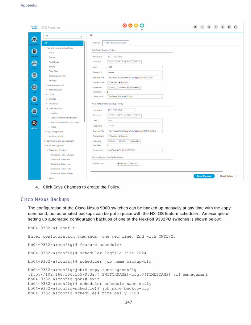
Appendix
247
4. Click Save Changes to create the Policy.
Cisco Nexus Backups
The configuration of the Cisco Nexus 9000 switches can be backed up manually at any time with the copy
command, but automated backups can be put in place with the NX-OS feature scheduler. An example of
setting up automated configuration backups of one of the FlexPod 9332PQ switches is shown below:
bb04-9332-a# conf t
Enter configuration commands, one per line. End with CNTL/Z.
bb04-9332-a(config)# feature scheduler
bb04-9332-a(config)# scheduler logfile size 1024
bb04-9332-a(config)# scheduler job name backup-cfg
bb04-9332-a(config-job)# copy running-config
tftp://192.168.156.155/9332/$(SWITCHNAME)-cfg.$(TIMESTAMP) vrf management
bb04-9332-a(config-job)# exit
bb04-9332-a(config)# scheduler schedule name daily
bb04-9332-a(config-schedule)# job name backup-cfg
bb04-9332-a(config-schedule)# time daily 2:00

Appendix
248
bb04-9332-a(config-schedule)# end
Show the job that has been setup:
bb04-9332-a# sh scheduler job
Job Name: backup-cfg
--------------------
copy running-config tftp://192.168.156.155/9332/$(SWITCHNAME)-cfg.$(TIMESTAMP) vrf
management
==============================================================================
bb04-9332-a# show scheduler schedule
Schedule Name : daily
---------------------------
User Name : admin
Schedule Type : Run every day at 2 Hrs 0 Mins
Last Execution Time : Sun Apr 9 02:00:00 2017
Last Completion Time: Sun Apr 9 02:00:01 2017
Execution count : 3
-----------------------------------------------
Job Name Last Execution Status
-----------------------------------------------
backup-cfg Success (0)
==============================================================================
Full documentation of use for the feature scheduler can be found at:
http://www.cisco.com/c/en/us/td/docs/switches/datacenter/nexus9000/sw/7-
x/system_management/configuration/guide/b_Cisco_Nexus_9000_Series_NX-
OS_System_Management_Configuration_Guide_7x/b_Cisco_Nexus_9000_Series_NX-
OS_System_Management_Configuration_Guide_7x_chapter_01010.html
VMware VCSA Backup
Basic backup of the vCenter Server Appliance is also available within the native capabilities of the VCSA,
though within the default solution this is manually initiated provide a scheduled solution. To create a backup,
complete the following steps:
1. Connect to the VCSA Console at https://<VCSA IP>:5480.

Appendix
249
2. Click Backup within the Summary section to open up the Backup Appliance Dialogue.
3. Specify:
a. the Protocol to use [HTTPS/HTTP/SCP/FTPS/FTP]
b. location of an empty directory to be used for the backup
c. the User name and password
4. Click Next.

Appendix
250
5. De-select some parts if they should be excluded from the backup.
6. Click Next.
7. Review the options selected and click Finish to begin the backup.
Restoration can be initiated with the backed up files using the Restore function of the VCSA 6.5 Installer.
Breakout Interface Configuration in the Cisco Nexus 9332PQ Switches
The 40Gb end to end FlexPod design in this document uses a pair of Nexus 9332PQ which is built with all
ports being of the 40 Gbps Quad Small Form Factor Pluggable Plus (QSFP+) type. If there is a need to
directly support a 10Gb Small Form Pluggable Plus (SFP+), this can be configured within the switch, and
connected to the 10Gb SFP+ device using a supported QSFP+ Breakout Cable.
Configuration of the QSFP+ ports will use the interface breakout command as shown in this example to turn
the 40G interface Ethernet 1/1 into 4x10G interfaces:
bb04-9332-a(config)# show running-config interface Ethernet1/1
interface Ethernet1/1
no switchport
bb04-9332-a(config)# interface breakout module 1 port 5 map 10g-4x
bb04-9332-a(config)# show running-config interface Ethernet1/1/1-4
interface Ethernet1/1/1

Appendix
251
interface Ethernet1/1/2
interface Ethernet1/1/3
interface Ethernet1/1/4
Breakout configurations that are no longer needed can be reverted with the no interface breakout command:
bb04-9332-a(config)# no interface breakout module 1 port 1 map 10g-4x
bb04-9332-a(config)#

About the Authors
252
About the Authors
John George, Technical Marketing Engineer, Cisco UCS Data Center Solutions Engineering, Cisco
Systems, Inc.
John George recently moved to Cisco from NetApp and has been focused on designing, developing,
validating, and supporting the FlexPod Converged Infrastructure since its inception. Before his roles with
FlexPod, he supported and administered a large worldwide training network and VPN infrastructure. John
holds a Master's degree in Computer Engineering from Clemson University.
Karthick Radhakrishnan, Systems Architect, Converged Infrastructure Engineering, NetApp
Karthick Radhakrishnan is a Systems Architect in the NetApp Infrastructure and Cloud Engineering team. He
focuses on the validating, supporting, implementing cloud infrastructure solutions that include NetApp
products. Prior to his current role, he was a networking tools developer at America Online supporting AOL
transit data network. Karthick worked in the IT industry for more than 14 years and he holds Master's degree
in Computer Application.
Acknowledgements
For their support and contribution to the design, validation, and creation of this Cisco Validated Design, the
authors would like to thank:
Ramesh Isaac, Cisco Systems, Inc.
Aaron Kirk, NetApp