FlexPod Data Center with Cisco Nexus 7000 and NetApp ... · FlexPod Data Center with Cisco Nexus...
93
FlexPod Data Center with Cisco Nexus 7000 and NetApp MetroCluster for Multisite Deployment Design and Deployment Guide Based on Cisco Unified Computing System, Cisco Nexus 7K, and NetApp MetroCluster Last Updated: November 18, 2013 Building Architectures to Solve Business Problems
Transcript of FlexPod Data Center with Cisco Nexus 7000 and NetApp ... · FlexPod Data Center with Cisco Nexus...
FlexPod Data Center with Cisco Nexus 7000 and NetApp MetroCluster for Multisite Deployment Design and Deployment Guide Based on Cisco Unified Computing System, Cisco Nexus 7K, and NetApp MetroCluster
Last Updated: November 18, 2013
Building Architectures to Solve Business Problems
Cisco Validated Design2
3About Cisco Validated Design (CVD) Program
About Cisco Validated Design (CVD) Program
The CVD program consists of systems and solutions designed, tested, and documented to facilitate
faster, more reliable, and more predictable customer deployments. For more information visit
http://www.cisco.com/go/designzone.
ALL DESIGNS, SPECIFICATIONS, STATEMENTS, INFORMATION, AND RECOMMENDATIONS (COLLEC-
TIVELY, "DESIGNS") IN THIS MANUAL ARE PRESENTED "AS IS," WITH ALL FAULTS. CISCO AND ITS
SUPPLIERS DISCLAIM ALL WARRANTIES, INCLUDING, WITHOUT LIMITATION, THE WARRANTY OF
MERCHANTABILITY, FITNESS FOR A PARTICULAR PURPOSE AND NONINFRINGEMENT OR ARISING
FROM A COURSE OF DEALING, USAGE, OR TRADE PRACTICE. IN NO EVENT SHALL CISCO OR ITS
SUPPLIERS BE LIABLE FOR ANY INDIRECT, SPECIAL, CONSEQUENTIAL, OR INCIDENTAL DAMAGES,
INCLUDING, WITHOUT LIMITATION, LOST PROFITS OR LOSS OR DAMAGE TO DATA ARISING OUT OF
THE USE OR INABILITY TO USE THE DESIGNS, EVEN IF CISCO OR ITS SUPPLIERS HAVE BEEN ADVISED
OF THE POSSIBILITY OF SUCH DAMAGES.
THE DESIGNS ARE SUBJECT TO CHANGE WITHOUT NOTICE. USERS ARE SOLELY RESPONSIBLE FOR
THEIR APPLICATION OF THE DESIGNS. THE DESIGNS DO NOT CONSTITUTE THE TECHNICAL OR
OTHER PROFESSIONAL ADVICE OF CISCO, ITS SUPPLIERS OR PARTNERS. USERS SHOULD CONSULT
THEIR OWN TECHNICAL ADVISORS BEFORE IMPLEMENTING THE DESIGNS. RESULTS MAY VARY
DEPENDING ON FACTORS NOT TESTED BY CISCO.
CCDE, CCENT, Cisco Eos, Cisco Lumin, Cisco Nexus, Cisco StadiumVision, Cisco TelePresence, Cisco
WebEx, the Cisco logo, DCE, and Welcome to the Human Network are trademarks; Changing the Way We
Work, Live, Play, and Learn and Cisco Store are service marks; and Access Registrar, Aironet, AsyncOS,
Bringing the Meeting To You, Catalyst, CCDA, CCDP, CCIE, CCIP, CCNA, CCNP, CCSP, CCVP, Cisco, the
Cisco Certified Internetwork Expert logo, Cisco IOS, Cisco Press, Cisco Systems, Cisco Systems Capital,
the Cisco Systems logo, Cisco Unity, Collaboration Without Limitation, EtherFast, EtherSwitch, Event Cen-
ter, Fast Step, Follow Me Browsing, FormShare, GigaDrive, HomeLink, Internet Quotient, IOS, iPhone,
iQuick Study, IronPort, the IronPort logo, LightStream, Linksys, MediaTone, MeetingPlace, MeetingPlace
Chime Sound, MGX, Networkers, Networking Academy, Network Registrar, PCNow, PIX, PowerPanels,
ProConnect, ScriptShare, SenderBase, SMARTnet, Spectrum Expert, StackWise, The Fastest Way to
Increase Your Internet Quotient, TransPath, WebEx, and the WebEx logo are registered trademarks of
Cisco Systems, Inc. and/or its affiliates in the United States and certain other countries.
All other trademarks mentioned in this document or website are the property of their respective owners.
The use of the word partner does not imply a partnership relationship between Cisco and any other com-
pany. (0809R)
© 2013 Cisco Systems, Inc. All rights reserved
AuthorsDerek Huckaby, Technical Marketing Engineer, Unified Fabric Switching Services Product Group, Cisco Systems
Derek Huckaby is a Technical Marketing Engineer for the Cisco Nexus 7000 Unified Fabric Switching products focusing on Cisco Nexus 7000 integration into FlexPod designs and Cisco Nexus 7000 services. Prior to joining the Nexus 7000 Product Marketing team, Derek led the team of Technical Marketing Engineers for the Data Center Application Services BU within Cisco. He began his work in network services at Cisco over 13 years ago specializing in application delivery and SSL termination solutions.
Haseeb Niazi, Technical Marketing Engineer, Server Access Virtualization Business Unit, Cisco Systems
Haseeb Niazi is a Technical Marketing Engineer in Cisco Server Access and Virtualization Business Unit. Haseeb has over 13 years of experience at Cisco dealing in Data Center, Security, and WAN Optimization related technologies. As a member of various solution teams and advanced services, Haseeb has helped many enterprise and service provider customers evaluate and deploy a wide range of Cisco solutions. Haseeb holds a master's degree in Computer Engineering from the University of Southern California.
Chris O'Brien, Technical Marketing Manager, Server Access Virtualization Business Unit, Cisco Systems
Chris O'Brien is currently focused on developing infrastructure best practices and solutions that are designed, tested, and documented to facilitate and improve customer deployments. Previously, O'Brien was an application developer and has worked in the IT industry for more than 15 years.
Jonathan Bell, Product Technical Marketing Engineer, NetApp Systems
Jonathan Bell is the Product TME for NetApp MetroCluster, developing best practices and solutions that integrate MetroCluster into IT ecosystems. Jonathan has worked as an Escalation Engineer in Customer Success and has gained experience over his career in the IT industry working with end to end SAN, Virtualization, and DR solutions. Before coming to NetApp, Jonathan worked in the Electric Utilities industry architecting and implementing critical IT infrastructure.
David Klem, Senior Reference Architect, NetApp Systems
David Klem is a Sr. Reference Architect in NetApp's Infrastructure and Cloud Engineering team, focusing on developing best practices and solutions for cloud-based architectures. Klem is one of the lead architects of the FlexPod, FlexPod Express and Secure Multi-Tenancy solutions developed by Cisco and NetApp. In addition, he has spoken with numerous customers and at industry events on converged infrastructure, networking, cloud computing and virtualization.
Corporate Headquarters:
Copyright © 2013 Cisco Systems, Inc. All rights reser
Cisco Systems, Inc., 170 West Tasman Drive, San Jose, CA 95134-1706 USA
Overview
FlexPod Data Center with Cisco Nexus 7000 and NetApp MetroCluster for Multisite Deployment
OverviewIn today's world, business continuity and reliable IT infrastructure are a crucial part of every successful company. Businesses rely on their information systems to run their operations successfully and therefore require their systems, specially their datacenters, to be available with near zero downtime. To support these organizational goals, datacenter architects have been exploring various high availability solutions to improve the availability and resiliency of datacenter services. In traditional single site datacenter architectures, high availability solutions mostly comprise of technologies such as application clustering and active-standby services architectures designed to improve the robustness of local systems i.e. systems within the single datacenter. To safeguard against site failures due to power or infrastructure outages, datacenter architects have begun to look at solutions that span multiple sites.
FlexPod® Data Center with NetApp® MetroCluster Software solution is based on stretched cluster architecture that spans geographically distributed metro sites to help improve availability of services in case of a site failure. The multisite architecture offers the ability to balance workloads between two data center utilizing non-disruptive workload mobility thereby enabling migration of services between sites without the need for sustaining an outage.
Solution ComponentsThe FlexPod® Data Center with NetApp® MetroCluster Software solution is developed using VMware vSphere Metro Storage Cluster (vMSC) configuration, Cisco Unified Fabric and Compute and NetApp MetroCluster Software.
VMware's vMSC solution defines best practices for workload mobility and load balancing of resources across Data Centers to improve the utilization and availability of data center resources to virtualized serves.
NetApp's MetroCluster is a synchronous replication solution between two NetApp controllers providing storage high availability and disaster recovery in a campus or metropolitan area. A MetroCluster configuration may exist in the same data center or across two different physical locations, clustered together. The MetroCluster manages one or multiple failures in the storage domain without disruption to data availability. For geographically separated data centers, NetApp's MetroCluster solution provides a number of key component benefits:
• Active-active controller: Provides high-availability failover capability between local and remote sites.
• SyncMirror®: Provides an up-to-date copy of data at the remote site (data can only be accessed by the remote controller after failover).
• MetroCluster configuration allows the ability to perform nondisruptive entire site maintenance with simple cluster takeover and giveback.
Cisco Nexus 7000's rich feature-set makes it an ideal platform for delivering the unified extended data center. In addition to providing a base switching and storage connectivity infrastructure, following features make Nexus 7000 an essential component of the solution:
5FlexPod Data Center with Cisco Nexus 7000 and NetApp MetroCluster for Multisite Deployment
Audience
• Overlay Transport Virtualization (OTV) - Provides layer 2 extension capability on a routed infrastructure
• Fibre Channel over Ethernet (FCoE) - Provides Ethernet and FC consolidation
• In Service Software Upgrade (ISSU) - Provides ability to upgrade with zero downtime
The well-established unified and integrated infrastructure provided by Cisco UCS has been further enhanced with multi-domain and self-service management capabilities to provide a seamless management platform. In addition to traditional management interfaces such as UCS Manager and power-shell, following two solutions enhance the integrated user experience:
• Cisco UCS Central - provides multi-domain UCS management
• Cisco UCS Director - provides converged infrastructure management across sites
By combining the rich feature portfolios of the VMware vSphere, NetApp Data ONTAP and Cisco Nexus 7000, the multisite FlexPod addresses geographically distributed data center requirements and delivers:
• Workload mobility
• Automated load balancing across sites
• Ease of maintenance
• Avoidance of disaster/downtime avoidance
AudienceThis document describes the architecture and deployment procedures of an infrastructure composed of Cisco®, NetApp, and VMware virtualization that use multisite FCoE-based storage serving NAS and SAN protocols. The intended audience for this document includes, but is not limited to, sales engineers, field consultants, professional services, IT managers, partner engineering, and customers who want to deploy the multisite FlexPod architecture with NetApp MetroCluster solution.
FlexPod Data Center with NetApp MetroCluster Software
FlexPod Data Center with NetApp MetroCluster Software OverviewFlexPod is the converged infrastructure solution with validated designs that speeds IT infrastructure and application deployment, while reducing cost, complexity, and project risk. Multisite FlexPod architecture expands on this by including the NetApp MetroCluster software solution, Cisco Nexus Networking, Cisco Unified Computing System™ (Cisco UCS®), and VMware vSphere software in a single package. The design is flexible enough such that the networking, compute, and storage can be easily scaled across two geographical locations. The available port density also enables the networking components to accommodate multiple configurations of this kind.
One benefit of the FlexPod architecture is the ability to customize or "flex" the environment to suit a customer's requirements, and the reference architecture detailed in this document highlights the resiliency, cost benefit, and ease of deployment of a storage solution based on MetroCluster. A storage system capable of multisite deployment enables both disaster avoidance and high availability for customer workloads.
6FlexPod Data Center with Cisco Nexus 7000 and NetApp MetroCluster for Multisite Deployment
FlexPod Data Center with NetApp MetroCluster Software
The multisite FlexPod design must meet following requirements as per VMware vMSC, NetApp MetroCluster, and Cisco product and technology guidelines:
• The maximum supported network latency between sites for the VMware ESXi™ management networks is 10ms round-trip time with VMware vSphere® Enterprise Plus Edition™ licenses.
• The maximum supported latency within a vMSC environment is 10ms RTT.
• A minimum of 622Mbps network bandwidth, configured with redundant links, is required for the ESXi vMotion network.
• The maximum distance for Fabric MetroCluster utilizing the MDS 9148 is 160 KM at 1Gbps.
• The maximum distance for the FCoE link between two Cisco Nexus 7000s is 80km.
Based on these design constraints, this multisite FlexPod solution is validated at a distance of 80km between the two data centers.
For deployments with distance requirements greater than 80km, see the VMware vSphere 5.1 on FlexPod with the Cisco Nexus 7000 CVD for details on leveraging iSCSI as the SAN boot protocol to avoid the FCoE distance limitation. Note that the NetApp Interoperability Matrix Tool describes the maximum distance between sites for MetroCluster, which will still apply when leveraging iSCSI.
Components of FlexPod Data Center with NetApp MetroCluster Software FlexPod Data Center with NetApp MetroCluster software is based on a Cisco Validated Design for a single-site Cisco Nexus 7000-based FlexPod unit utilizing NetApp Data ONTAP® operating in 7-Mode.
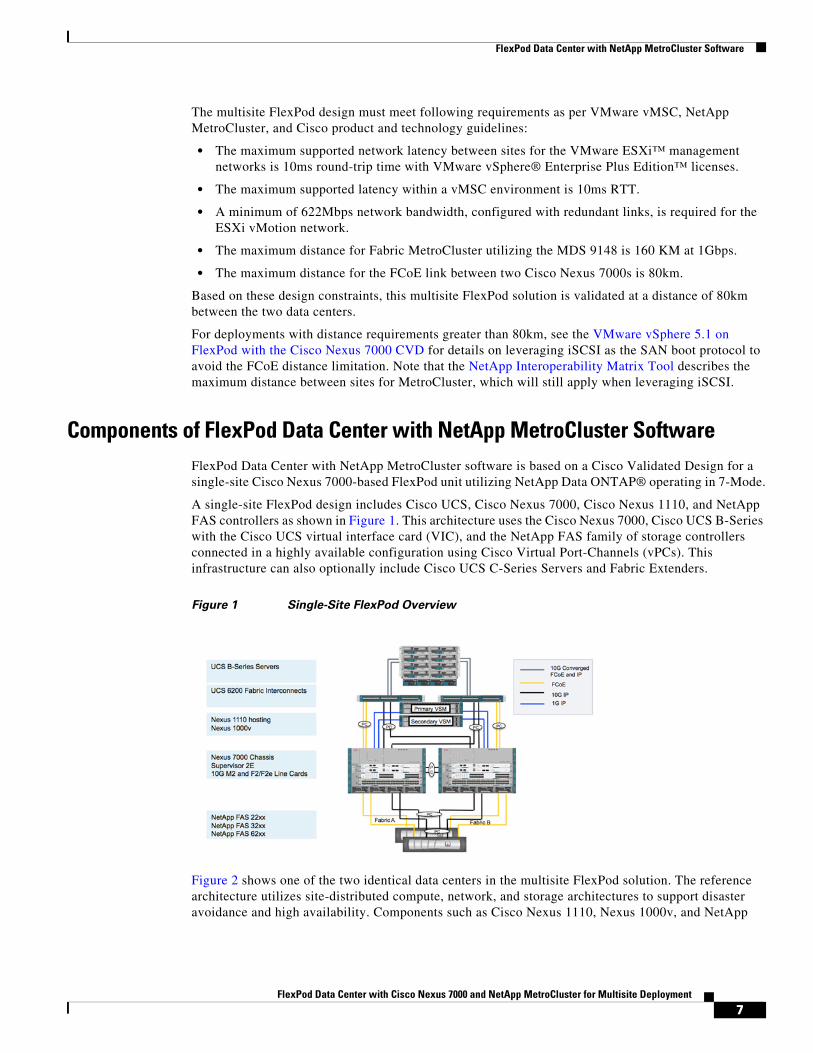
A single-site FlexPod design includes Cisco UCS, Cisco Nexus 7000, Cisco Nexus 1110, and NetApp FAS controllers as shown in Figure 1. This architecture uses the Cisco Nexus 7000, Cisco UCS B-Series with the Cisco UCS virtual interface card (VIC), and the NetApp FAS family of storage controllers connected in a highly available configuration using Cisco Virtual Port-Channels (vPCs). This infrastructure can also optionally include Cisco UCS C-Series Servers and Fabric Extenders.
Figure 1 Single-Site FlexPod Overview
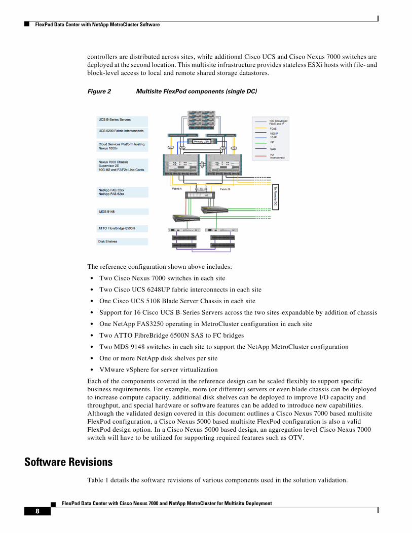
Figure 2 shows one of the two identical data centers in the multisite FlexPod solution. The reference architecture utilizes site-distributed compute, network, and storage architectures to support disaster avoidance and high availability. Components such as Cisco Nexus 1110, Nexus 1000v, and NetApp
7FlexPod Data Center with Cisco Nexus 7000 and NetApp MetroCluster for Multisite Deployment
FlexPod Data Center with NetApp MetroCluster Software
controllers are distributed across sites, while additional Cisco UCS and Cisco Nexus 7000 switches are deployed at the second location. This multisite infrastructure provides stateless ESXi hosts with file- and block-level access to local and remote shared storage datastores.
Figure 2 Multisite FlexPod components (single DC)
The reference configuration shown above includes:
• Two Cisco Nexus 7000 switches in each site
• Two Cisco UCS 6248UP fabric interconnects in each site
• One Cisco UCS 5108 Blade Server Chassis in each site
• Support for 16 Cisco UCS B-Series Servers across the two sites-expandable by addition of chassis
• One NetApp FAS3250 operating in MetroCluster configuration in each site
• Two ATTO FibreBridge 6500N SAS to FC bridges
• Two MDS 9148 switches in each site to support the NetApp MetroCluster configuration
• One or more NetApp disk shelves per site
• VMware vSphere for server virtualization
Each of the components covered in the reference design can be scaled flexibly to support specific business requirements. For example, more (or different) servers or even blade chassis can be deployed to increase compute capacity, additional disk shelves can be deployed to improve I/O capacity and throughput, and special hardware or software features can be added to introduce new capabilities. Although the validated design covered in this document outlines a Cisco Nexus 7000 based multisite FlexPod configuration, a Cisco Nexus 5000 based multisite FlexPod configuration is also a valid FlexPod design option. In a Cisco Nexus 5000 based design, an aggregation level Cisco Nexus 7000 switch will have to be utilized for supporting required features such as OTV.
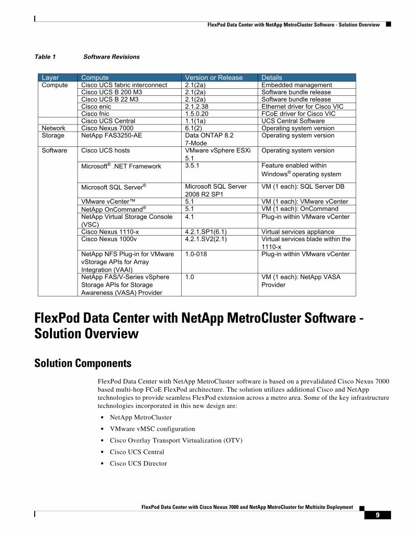
Software RevisionsTable 1 details the software revisions of various components used in the solution validation.
8FlexPod Data Center with Cisco Nexus 7000 and NetApp MetroCluster for Multisite Deployment
FlexPod Data Center with NetApp MetroCluster Software - Solution Overview
Table 1 Software Revisions
FlexPod Data Center with NetApp MetroCluster Software - Solution Overview
Solution ComponentsFlexPod Data Center with NetApp MetroCluster software is based on a prevalidated Cisco Nexus 7000 based multi-hop FCoE FlexPod architecture. The solution utilizes additional Cisco and NetApp technologies to provide seamless FlexPod extension across a metro area. Some of the key infrastructure technologies incorporated in this new design are:
• NetApp MetroCluster
• VMware vMSC configuration
• Cisco Overlay Transport Virtualization (OTV)
• Cisco UCS Central
• Cisco UCS Director
Layer Compute Version or Release DetailsCompute Cisco UCS fabric interconnect 2.1(2a) Embedded management
Cisco UCS B 200 M3 2.1(2a) Software bundle releaseCisco UCS B 22 M3 2.1(2a) Software bundle releaseCisco enic 2.1.2.38 Ethernet driver for Cisco VICCisco fnic 1.5.0.20 FCoE driver for Cisco VICCisco UCS Central 1.1(1a) UCS Central Software
Network Cisco Nexus 7000 6.1(2) Operating system versionStorage NetApp FAS3250-AE Data ONTAP 8.2
7-ModeOperating system version
Software Cisco UCS hosts VMware vSphere ESXi 5.1
Operating system version
Microsoft® .NET Framework 3.5.1 Feature enabled within Windows® operating system
Microsoft SQL Server® Microsoft SQL Server 2008 R2 SP1
VM (1 each): SQL Server DB
VMware vCenter™ 5.1 VM (1 each): VMware vCenterNetApp OnCommand® 5.1 VM (1 each): OnCommandNetApp Virtual Storage Console (VSC)
4.1 Plug-in within VMware vCenter
Cisco Nexus 1110-x 4.2.1.SP1(6.1) Virtual services appliance Cisco Nexus 1000v 4.2.1.SV2(2.1) Virtual services blade within the
1110-x NetApp NFS Plug-in for VMware vStorage APIs for Array Integration (VAAI)
1.0-018 Plug-in within VMware vCenter
NetApp FAS/V-Series vSphere Storage APIs for Storage Awareness (VASA) Provider
1.0 VM (1 each): NetApp VASA Provider
9FlexPod Data Center with Cisco Nexus 7000 and NetApp MetroCluster for Multisite Deployment
FlexPod Data Center with NetApp MetroCluster Software - Solution Overview
Note Cisco UCS Central and Cisco UCS Directors are not deployed together. The solution supports either Cisco UCS Central OR UCS Director.
These core technologies enable network, compute and storage administrators to provide a single site like seamless end-use experience across geographically separated Data Centers. In this multi-site design, a single vCenter manages all the ESXi hosts regardless of their location. A site-distributed Nexus 1000v architecture provides consistent switching infrastructure in both the DCs. Cisco OTV extends the VLANs between the sites enabling VM migration across the WAN/Layer-3 boundary. UCS Central manages each sites' Cisco UCS domain. Cisco UCS Central consolidates and simplifies UCS administration by implementing global policies and profiles across Cisco UCS domains. This global capability allows administrators to migrate physical hosts across Cisco UCS environments. The NetApp MetroCluster solution provides the much-needed unified and resilient storage configuration across the two sites. As a result of the interaction between these technologies, a DC admin delivers an easily manageable highly available Integrated Compute Stack.
MetroCluster SolutionNetApp MetroCluster is a highly cost-effective, synchronous replication solution for combining high availability and disaster recovery in a campus or metropolitan area to protect against both site disasters and hardware outages. NetApp MetroCluster provides automatic recovery for any single storage component failure and a highly efficient single-command recovery in case of major site disasters. It provides solutions with zero data loss and recovery within minutes rather than hours, and therefore, improved RPO and RTO. The NetApp MetroCluster solution is a basic building block and core component of the multisite FlexPod solution. For more information on the MetroCluster solution, refer to http://www.netapp.com/us/products/protection-software/metrocluster.aspx.
VMware vMSC vSphere Metro Storage Cluster (vMSC) is a certified configuration with NetApp MetroCluster storage architectures. The vMSC configuration is designed to maintain data availability beyond a single physical or logical site. Because business-critical solutions are increasingly hosted in virtualized data centers, there is an increased emphasis on improving the robustness of the infrastructure. This enables businesses to reap the economic and operational benefits of virtualization without compromising on availability or quality of service. Planning a robust high-availability infrastructure solution for virtual data center environments hosting mission-critical applications is of utmost importance.
Leveraging the configuration, failure planning and testing, and high-availability design of the vMSC solution along with the deep integration with VMware technologies makes this an excellent foundation for the FlexPod Data Center with NetApp MetroCluster Software Solution.
VMware with its high-availability and fault-tolerance features provides uniform failover protection against hardware and software failures within a virtualized IT environment.
VMware vCenter is a centralized management tool for ESX® clusters that helps administrators to perform core functions such as VM provisioning, vMotion operation, DRS, and so on. The VMware virtual infrastructure should be designed considering service availability.
VMware DRS aggregates the host resources in a cluster and is primarily used to load balance within a cluster in virtual infrastructure. VMware DRS primarily calculates the CPU and memory resources to perform load balancing in a cluster. Many features are available within VMware DRS that can be leveraged in a NetApp MetroCluster environment.
10FlexPod Data Center with Cisco Nexus 7000 and NetApp MetroCluster for Multisite Deployment
FlexPod Data Center with NetApp MetroCluster Software - Solution Overview
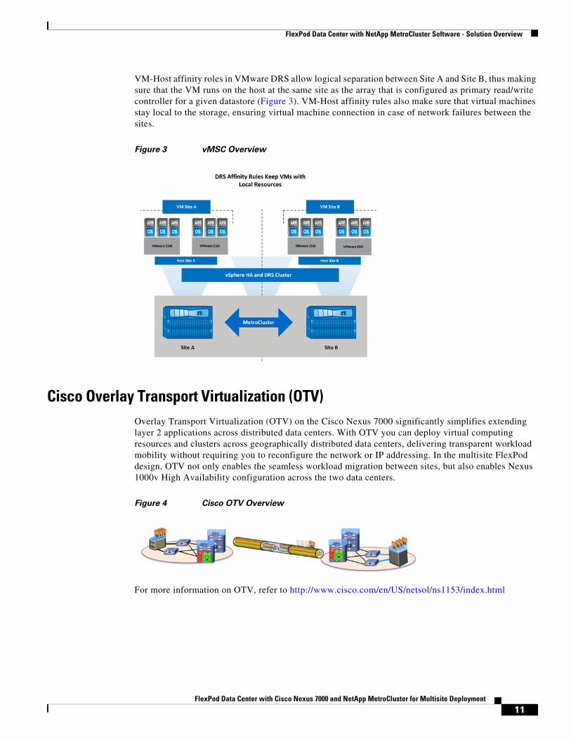
VM-Host affinity roles in VMware DRS allow logical separation between Site A and Site B, thus making sure that the VM runs on the host at the same site as the array that is configured as primary read/write controller for a given datastore (Figure 3). VM-Host affinity rules also make sure that virtual machines stay local to the storage, ensuring virtual machine connection in case of network failures between the sites.
Figure 3 vMSC Overview
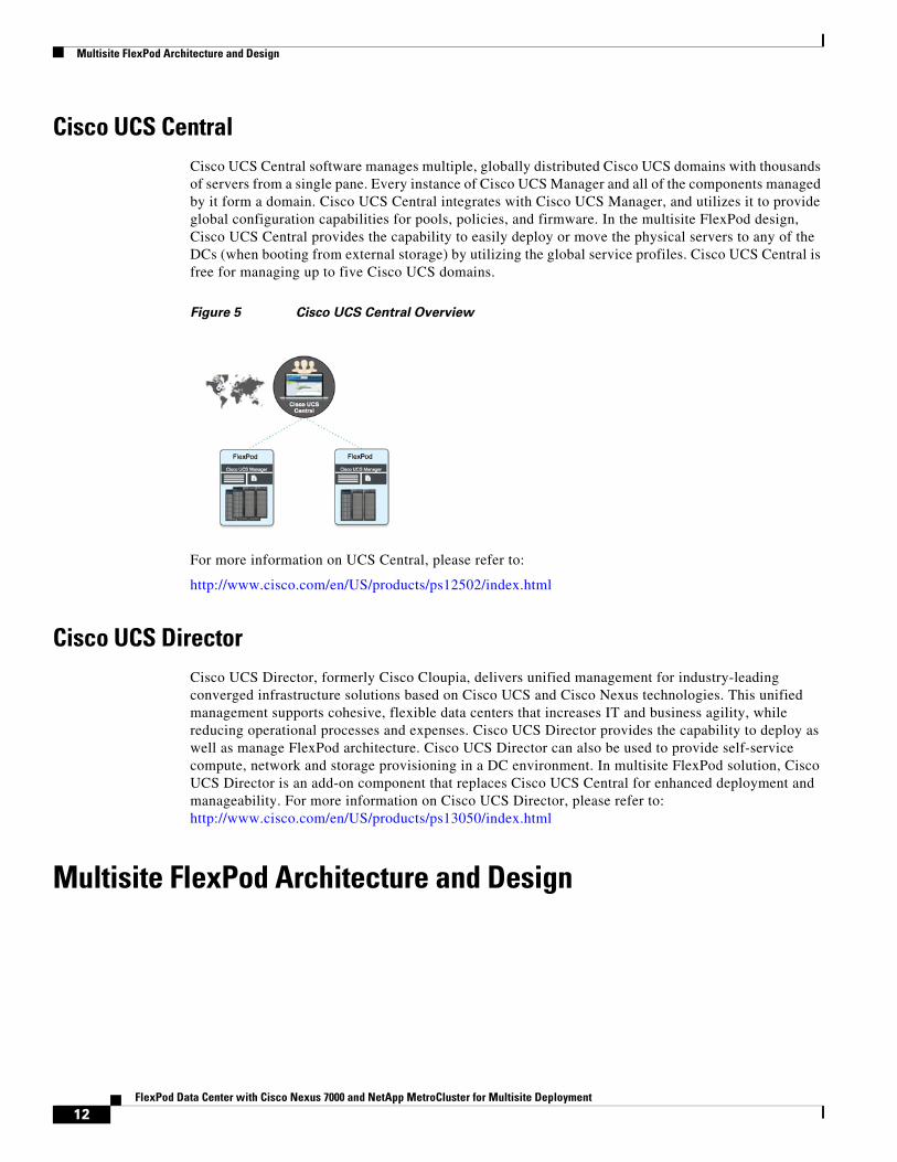
Cisco Overlay Transport Virtualization (OTV)Overlay Transport Virtualization (OTV) on the Cisco Nexus 7000 significantly simplifies extending layer 2 applications across distributed data centers. With OTV you can deploy virtual computing resources and clusters across geographically distributed data centers, delivering transparent workload mobility without requiring you to reconfigure the network or IP addressing. In the multisite FlexPod design, OTV not only enables the seamless workload migration between sites, but also enables Nexus 1000v High Availability configuration across the two data centers.
Figure 4 Cisco OTV Overview
For more information on OTV, refer to http://www.cisco.com/en/US/netsol/ns1153/index.html
11FlexPod Data Center with Cisco Nexus 7000 and NetApp MetroCluster for Multisite Deployment
Multisite FlexPod Architecture and Design
Cisco UCS CentralCisco UCS Central software manages multiple, globally distributed Cisco UCS domains with thousands of servers from a single pane. Every instance of Cisco UCS Manager and all of the components managed by it form a domain. Cisco UCS Central integrates with Cisco UCS Manager, and utilizes it to provide global configuration capabilities for pools, policies, and firmware. In the multisite FlexPod design, Cisco UCS Central provides the capability to easily deploy or move the physical servers to any of the DCs (when booting from external storage) by utilizing the global service profiles. Cisco UCS Central is free for managing up to five Cisco UCS domains.
Figure 5 Cisco UCS Central Overview
For more information on UCS Central, please refer to:
http://www.cisco.com/en/US/products/ps12502/index.html
Cisco UCS DirectorCisco UCS Director, formerly Cisco Cloupia, delivers unified management for industry-leading converged infrastructure solutions based on Cisco UCS and Cisco Nexus technologies. This unified management supports cohesive, flexible data centers that increases IT and business agility, while reducing operational processes and expenses. Cisco UCS Director provides the capability to deploy as well as manage FlexPod architecture. Cisco UCS Director can also be used to provide self-service compute, network and storage provisioning in a DC environment. In multisite FlexPod solution, Cisco UCS Director is an add-on component that replaces Cisco UCS Central for enhanced deployment and manageability. For more information on Cisco UCS Director, please refer to: http://www.cisco.com/en/US/products/ps13050/index.html
Multisite FlexPod Architecture and Design
12FlexPod Data Center with Cisco Nexus 7000 and NetApp MetroCluster for Multisite Deployment
Multisite FlexPod Architecture and Design
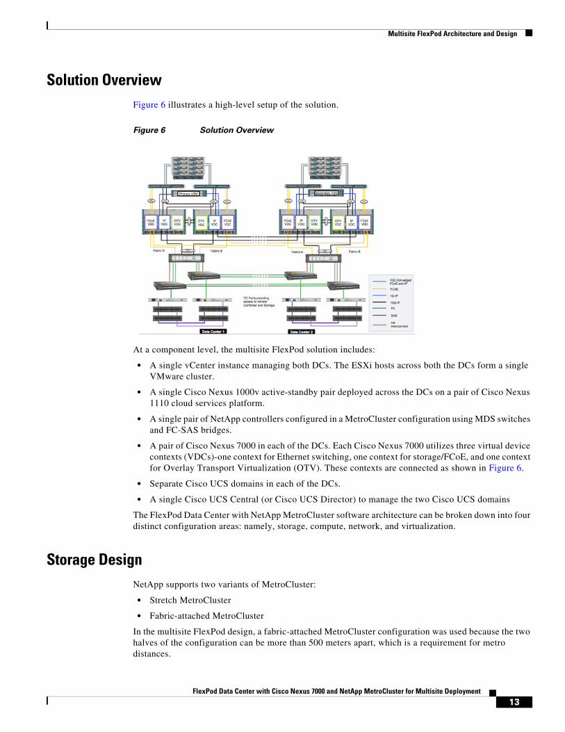
Solution OverviewFigure 6 illustrates a high-level setup of the solution.
Figure 6 Solution Overview
At a component level, the multisite FlexPod solution includes:
• A single vCenter instance managing both DCs. The ESXi hosts across both the DCs form a single VMware cluster.
• A single Cisco Nexus 1000v active-standby pair deployed across the DCs on a pair of Cisco Nexus 1110 cloud services platform.
• A single pair of NetApp controllers configured in a MetroCluster configuration using MDS switches and FC-SAS bridges.
• A pair of Cisco Nexus 7000 in each of the DCs. Each Cisco Nexus 7000 utilizes three virtual device contexts (VDCs)-one context for Ethernet switching, one context for storage/FCoE, and one context for Overlay Transport Virtualization (OTV). These contexts are connected as shown in Figure 6.
• Separate Cisco UCS domains in each of the DCs.
• A single Cisco UCS Central (or Cisco UCS Director) to manage the two Cisco UCS domains
The FlexPod Data Center with NetApp MetroCluster software architecture can be broken down into four distinct configuration areas: namely, storage, compute, network, and virtualization.
Storage DesignNetApp supports two variants of MetroCluster:
• Stretch MetroCluster
• Fabric-attached MetroCluster
In the multisite FlexPod design, a fabric-attached MetroCluster configuration was used because the two halves of the configuration can be more than 500 meters apart, which is a requirement for metro distances.
13FlexPod Data Center with Cisco Nexus 7000 and NetApp MetroCluster for Multisite Deployment
Multisite FlexPod Architecture and Design
Note In a MetroCluster environment, NetApp controllers can only be configured in Data ONTAP operating in 7-Mode.
Fabric-attached MetroCluster configurations support both active-passive and active-active configurations.
Active-Passive Configuration
In this configuration, data is mirrored between the controllers, but the remote (passive) node does not serve data unless it has taken over for the local (active) node. Mirroring the passive node's root volume is optional. However, both nodes must have all licenses for MetroCluster configuration installed to enable remote takeover.
Active-Active Configuration
In this configuration, data is mirrored between the controllers, but each node serves its own data set. In the event of storage failure, a takeover will occur, and one controller will serve both data sets. Mirroring of the passive node's root volume is required. Both nodes must have all licenses for MetroCluster configuration installed to enable remote takeover.
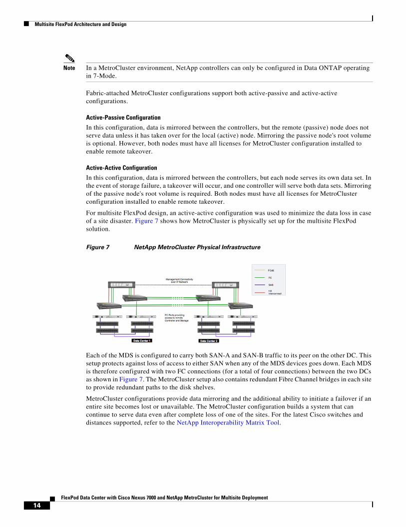
For multisite FlexPod design, an active-active configuration was used to minimize the data loss in case of a site disaster. Figure 7 shows how MetroCluster is physically set up for the multisite FlexPod solution.
Figure 7 NetApp MetroCluster Physical Infrastructure
Each of the MDS is configured to carry both SAN-A and SAN-B traffic to its peer on the other DC. This setup protects against loss of access to either SAN when any of the MDS devices goes down. Each MDS is therefore configured with two FC connections (for a total of four connections) between the two DCs as shown in Figure 7. The MetroCluster setup also contains redundant Fibre Channel bridges in each site to provide redundant paths to the disk shelves.
MetroCluster configurations provide data mirroring and the additional ability to initiate a failover if an entire site becomes lost or unavailable. The MetroCluster configuration builds a system that can continue to serve data even after complete loss of one of the sites. For the latest Cisco switches and distances supported, refer to the NetApp Interoperability Matrix Tool.
14FlexPod Data Center with Cisco Nexus 7000 and NetApp MetroCluster for Multisite Deployment
Multisite FlexPod Architecture and Design
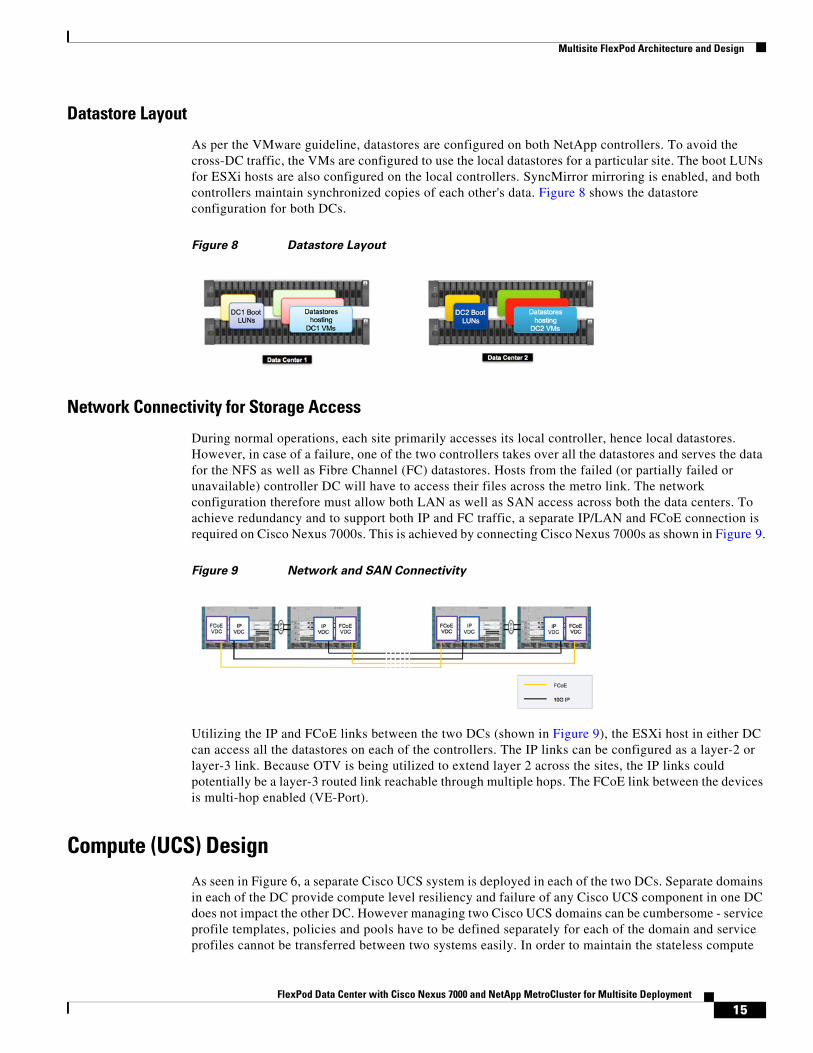
Datastore Layout
As per the VMware guideline, datastores are configured on both NetApp controllers. To avoid the cross-DC traffic, the VMs are configured to use the local datastores for a particular site. The boot LUNs for ESXi hosts are also configured on the local controllers. SyncMirror mirroring is enabled, and both controllers maintain synchronized copies of each other's data. Figure 8 shows the datastore configuration for both DCs.
Figure 8 Datastore Layout
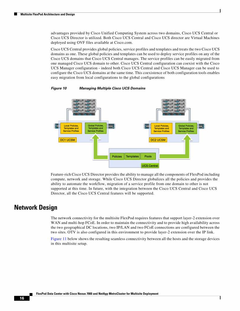
Network Connectivity for Storage Access
During normal operations, each site primarily accesses its local controller, hence local datastores. However, in case of a failure, one of the two controllers takes over all the datastores and serves the data for the NFS as well as Fibre Channel (FC) datastores. Hosts from the failed (or partially failed or unavailable) controller DC will have to access their files across the metro link. The network configuration therefore must allow both LAN as well as SAN access across both the data centers. To achieve redundancy and to support both IP and FC traffic, a separate IP/LAN and FCoE connection is required on Cisco Nexus 7000s. This is achieved by connecting Cisco Nexus 7000s as shown in Figure 9.
Figure 9 Network and SAN Connectivity
Utilizing the IP and FCoE links between the two DCs (shown in Figure 9), the ESXi host in either DC can access all the datastores on each of the controllers. The IP links can be configured as a layer-2 or layer-3 link. Because OTV is being utilized to extend layer 2 across the sites, the IP links could potentially be a layer-3 routed link reachable through multiple hops. The FCoE link between the devices is multi-hop enabled (VE-Port).
Compute (UCS) DesignAs seen in Figure 6, a separate Cisco UCS system is deployed in each of the two DCs. Separate domains in each of the DC provide compute level resiliency and failure of any Cisco UCS component in one DC does not impact the other DC. However managing two Cisco UCS domains can be cumbersome - service profile templates, policies and pools have to be defined separately for each of the domain and service profiles cannot be transferred between two systems easily. In order to maintain the stateless compute
15FlexPod Data Center with Cisco Nexus 7000 and NetApp MetroCluster for Multisite Deployment
Multisite FlexPod Architecture and Design
advantages provided by Cisco Unified Computing System across two domains, Cisco UCS Central or Cisco UCS Director is utilized. Both Cisco UCS Central and Cisco UCS director are Virtual Machines deployed using OVF files available at Cisco.com.
Cisco UCS Central provides global policies, service profiles and templates and treats the two Cisco UCS domains as one. These global policies and templates can be used to deploy service profiles on any of the Cisco UCS domains that Cisco UCS Central manages. The service profiles can be easily migrated from one managed Cisco UCS domain to other. Cisco UCS Central configuration can coexist with the Cisco UCS Manager configuration - indeed both Cisco UCS Central and Cisco UCS Manager can be used to configure the Cisco UCS domains at the same time. This coexistence of both configuration tools enables easy migration from local configurations to the global configurations
Figure 10 Managing Multiple Cisco UCS Domains
Feature-rich Cisco UCS Director provides the ability to manage all the components of FlexPod including compute, network and storage. While Cisco UCS Director globalizes all the policies and provides the ability to automate the workflow, migration of a service profile from one domain to other is not supported at this time. In future, with the integration between the Cisco UCS Central and Cisco UCS Director, all the Cisco UCS Central features will be supported.
Network DesignThe network connectivity for the multisite FlexPod requires features that support layer-2 extension over WAN and multi-hop FCoE. In order to maintain the connectivity and to provide high availability across the two geographical DC locations, two IP/LAN and two FCoE connections are configured between the two sites. OTV is also configured in this environment to provide layer-2 extension over the IP link.
Figure 11 below shows the resulting seamless connectivity between all the hosts and the storage devices in this multisite setup.
16FlexPod Data Center with Cisco Nexus 7000 and NetApp MetroCluster for Multisite Deployment
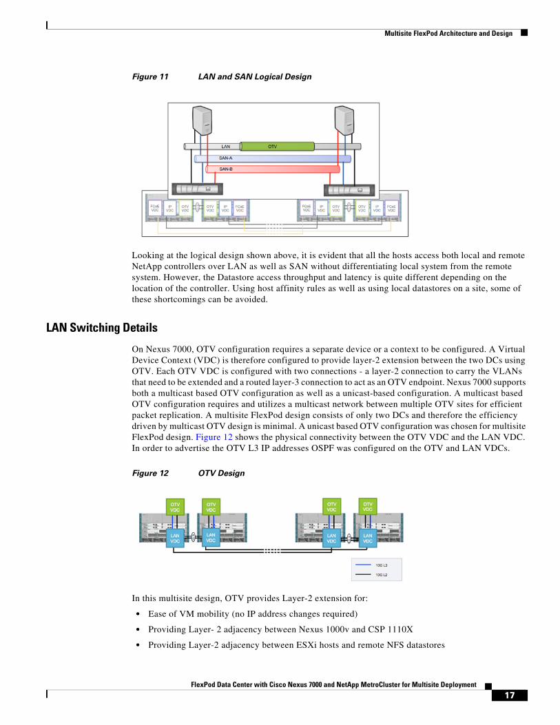
Multisite FlexPod Architecture and Design
Figure 11 LAN and SAN Logical Design
Looking at the logical design shown above, it is evident that all the hosts access both local and remote NetApp controllers over LAN as well as SAN without differentiating local system from the remote system. However, the Datastore access throughput and latency is quite different depending on the location of the controller. Using host affinity rules as well as using local datastores on a site, some of these shortcomings can be avoided.
LAN Switching Details
On Nexus 7000, OTV configuration requires a separate device or a context to be configured. A Virtual Device Context (VDC) is therefore configured to provide layer-2 extension between the two DCs using OTV. Each OTV VDC is configured with two connections - a layer-2 connection to carry the VLANs that need to be extended and a routed layer-3 connection to act as an OTV endpoint. Nexus 7000 supports both a multicast based OTV configuration as well as a unicast-based configuration. A multicast based OTV configuration requires and utilizes a multicast network between multiple OTV sites for efficient packet replication. A multisite FlexPod design consists of only two DCs and therefore the efficiency driven by multicast OTV design is minimal. A unicast based OTV configuration was chosen for multisite FlexPod design. Figure 12 shows the physical connectivity between the OTV VDC and the LAN VDC. In order to advertise the OTV L3 IP addresses OSPF was configured on the OTV and LAN VDCs.
Figure 12 OTV Design
In this multisite design, OTV provides Layer-2 extension for:
• Ease of VM mobility (no IP address changes required)
• Providing Layer- 2 adjacency between Nexus 1000v and CSP 1110X
• Providing Layer-2 adjacency between ESXi hosts and remote NFS datastores
17FlexPod Data Center with Cisco Nexus 7000 and NetApp MetroCluster for Multisite Deployment
Multisite FlexPod Architecture and Design
Virtual Switching Details
FlexPod utilizes Nexus 1000v as a VMware virtual distributed switch. The Nexus 1000v is hosted on Nexus 1110 Cloud Service Platform. Both Cisco Nexus 1000v as well as Nexus 1110 support an active-standby high availability for redundancy. In a multisite FlexPod design, the two 1110 platforms are distributed across the two sites. The layer-2 extension capability provided by OTV, between these two sites, enables the Cloud Service Platform as well as Nexus 1000v to establish high-availability pairing. This distributed device configuration allows access to virtual supervisor module (VSM) even if one of the sites is completely down. Figure 13 shows the connectivity details for Nexus 1110 and VSM connectivity.
Figure 13 Virtual Switching Design
OTV extends both packet and control VLANs across the two sites and Nexus 1110 and VSMs form layer-2 adjacency over layer-3 network.
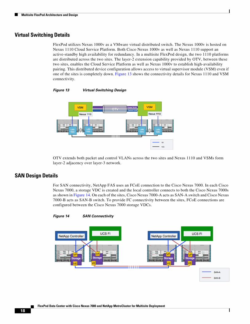
SAN Design Details
For SAN connectivity, NetApp FAS uses an FCoE connection to the Cisco Nexus 7000. In each Cisco Nexus 7000, a storage VDC is created and the local controller connects to both the Cisco Nexus 7000s as shown in Figure 14. On each of the sites, Cisco Nexus 7000-A acts as SAN-A switch and Cisco Nexus 7000-B acts as SAN-B switch. To provide FC connectivity between the sites, FCoE connections are configured between the Cisco Nexus 7000 storage VDCs.
Figure 14 SAN Connectivity
18FlexPod Data Center with Cisco Nexus 7000 and NetApp MetroCluster for Multisite Deployment
Multisite FlexPod Architecture and Design
As shown in Figure 14, two redundant paths are configured between the two sites for SAN resiliency. The ports between the Cisco Nexus 7000 switches are configured as FCoE VE_ports to enable multi-hop FCoE. By using this configuration, each ESXi host has access to both the NetApp controllers. The boot policies used in the boot-from-SAN configuration are very similar to single-site FlexPod infrastructure. The SAN path to the local controller becomes the preferred path, and the SAN path to the remote controller is set up as a secondary path to be used in case of NetApp controller failure.
VMware DesignLike all the other FlexPod designs, ESXi hosts are configured to boot from SAN for supporting stateless computing. Each ESXi boot LUN is created on the local NetApp controller to avoid booting across the WAN. NFS datastores are created on both the NetApp controllers to host the VMs.
Note VMware recommends creating at least two similar datastores on each site and to use Storage DRS.
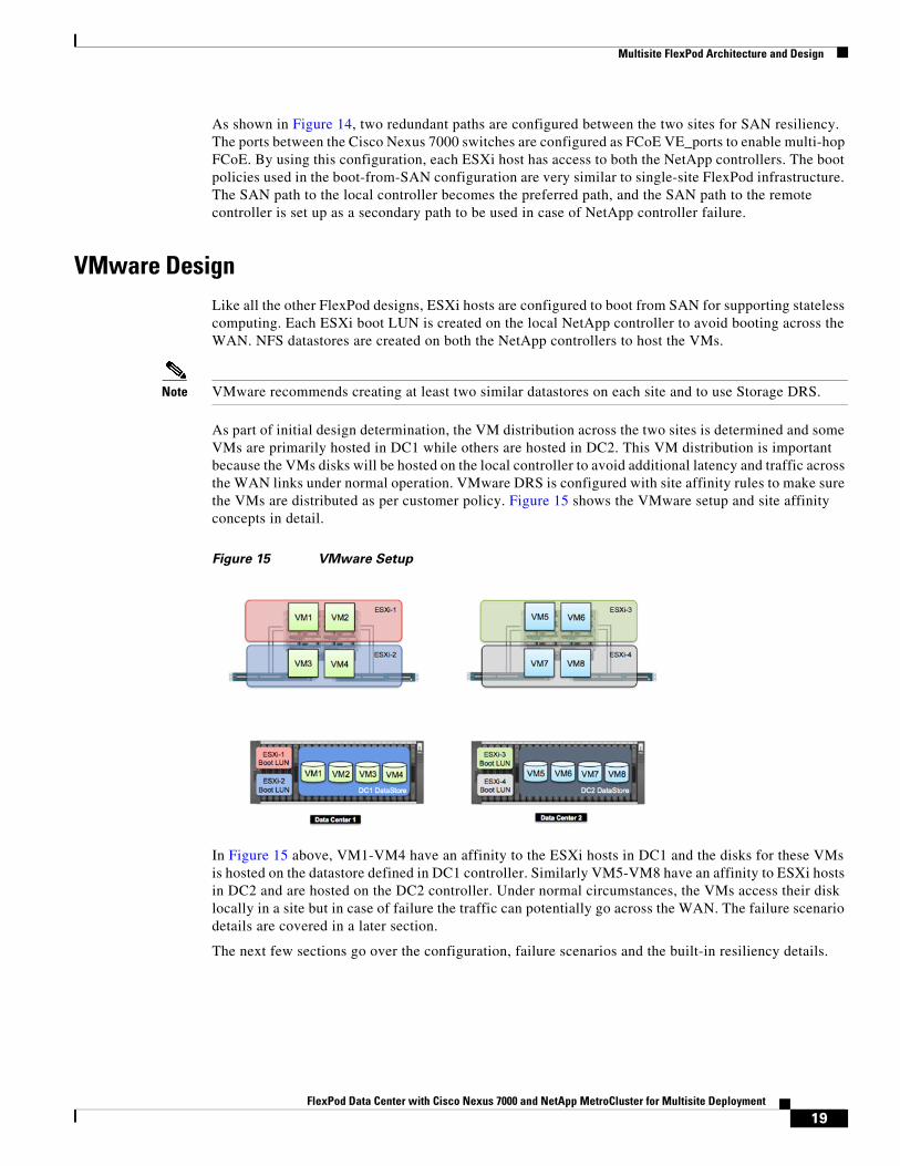
As part of initial design determination, the VM distribution across the two sites is determined and some VMs are primarily hosted in DC1 while others are hosted in DC2. This VM distribution is important because the VMs disks will be hosted on the local controller to avoid additional latency and traffic across the WAN links under normal operation. VMware DRS is configured with site affinity rules to make sure the VMs are distributed as per customer policy. Figure 15 shows the VMware setup and site affinity concepts in detail.
Figure 15 VMware Setup
In Figure 15 above, VM1-VM4 have an affinity to the ESXi hosts in DC1 and the disks for these VMs is hosted on the datastore defined in DC1 controller. Similarly VM5-VM8 have an affinity to ESXi hosts in DC2 and are hosted on the DC2 controller. Under normal circumstances, the VMs access their disk locally in a site but in case of failure the traffic can potentially go across the WAN. The failure scenario details are covered in a later section.
The next few sections go over the configuration, failure scenarios and the built-in resiliency details.
19FlexPod Data Center with Cisco Nexus 7000 and NetApp MetroCluster for Multisite Deployment
Configuration Details
Configuration Details
Configuration GuidelinesThis document provides details for configuring a fully redundant, highly available multisite configuration for a FlexPod unit with Data ONTAP storage. As mentioned previously, the configuration in this solution is based on Cisco Nexus 7000 based FlexPod. A step-by-step basic configuration of components is therefore deferred to the original Cisco Validated Design (CVD). References to sections in the existing documents are provided. This solution deployment guide will cover the configuration of additional components and changes to existing design that enable a multisite FlexPod deployment.
This document is intended to provide a reference configuration because the customer environments vary considerably in multisite configurations. However, an effort has been made to keep the VLANs, port configurations, and naming conventions consistent with the existing CVDs. The following tables and figures provide the physical connectivity details, including port information as well as VLANs/VSANs used.
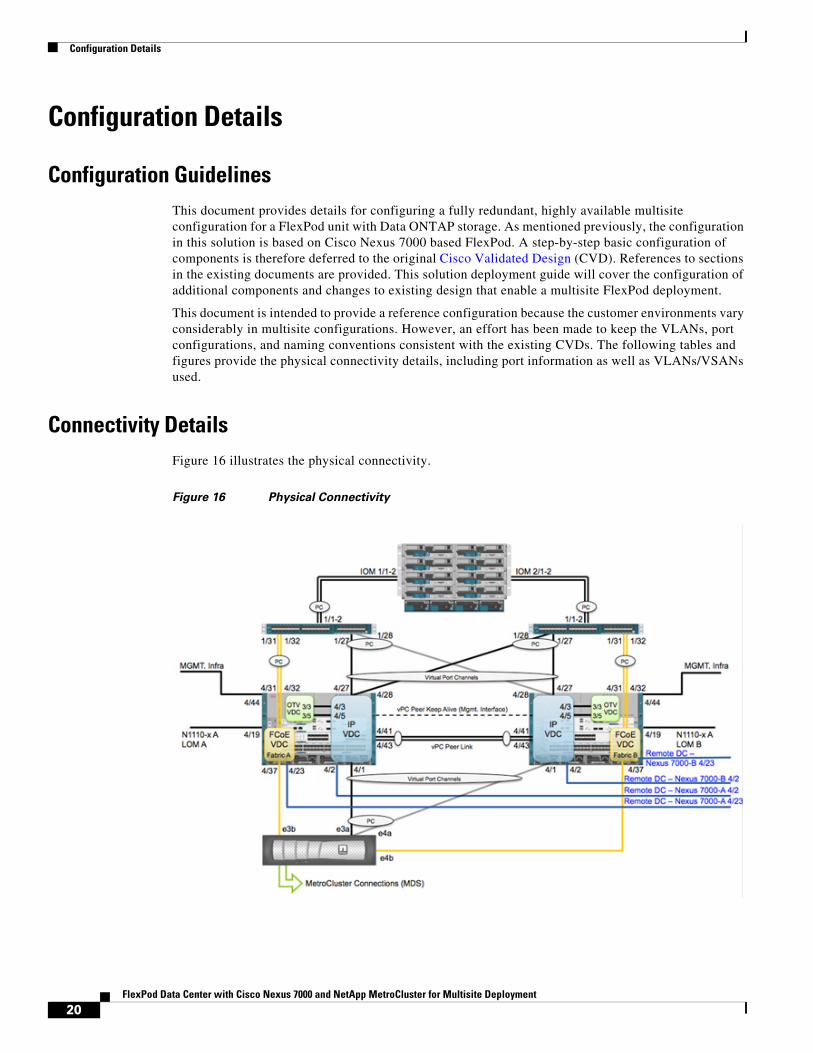
Connectivity DetailsFigure 16 illustrates the physical connectivity.
Figure 16 Physical Connectivity
20FlexPod Data Center with Cisco Nexus 7000 and NetApp MetroCluster for Multisite Deployment
Configuration Details
Figure 16 shows connectivity details of one of the two sites. Both sites are connected and configured exactly the same. The number of connections as well as the port IDs for these connections are also the same. This figure does not cover the MetroCluster connectivity details because these details are covered separately.
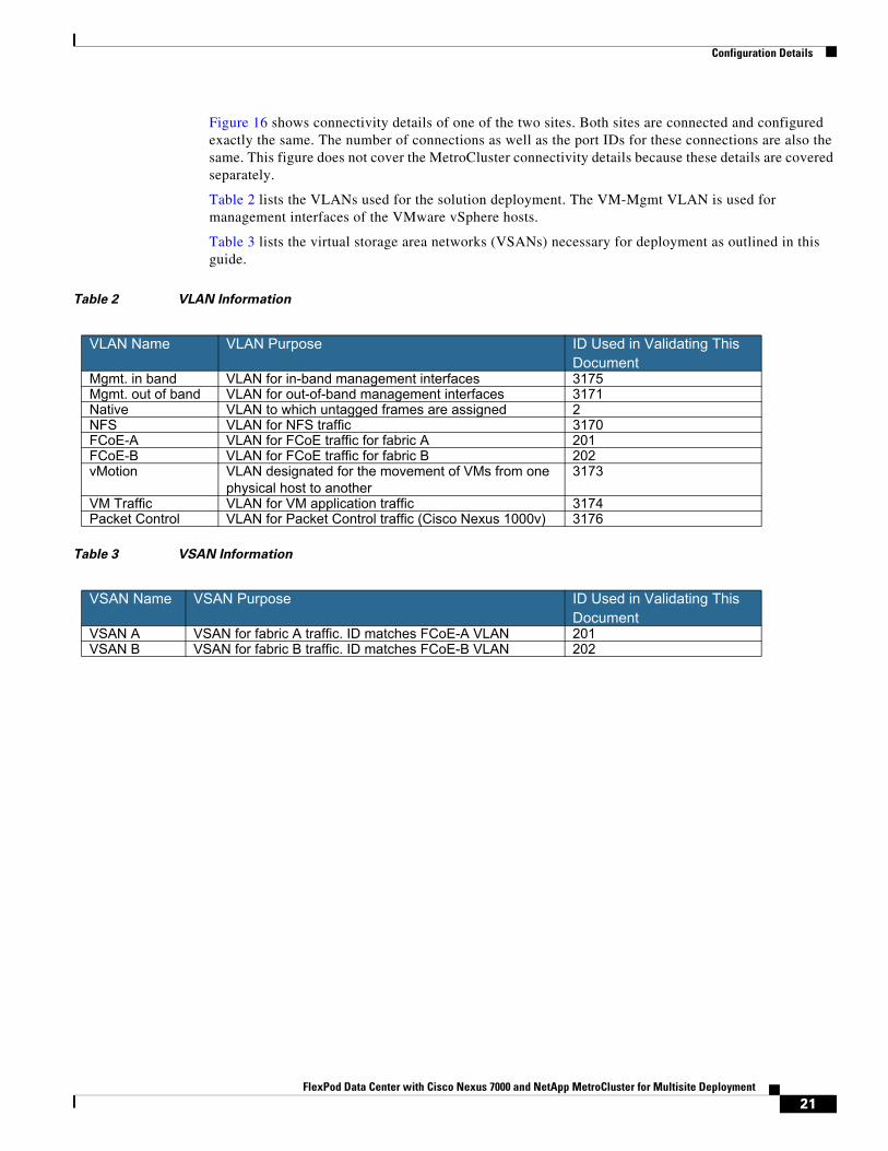
Table 2 lists the VLANs used for the solution deployment. The VM-Mgmt VLAN is used for management interfaces of the VMware vSphere hosts.
Table 3 lists the virtual storage area networks (VSANs) necessary for deployment as outlined in this guide.
Table 2 VLAN Information
Table 3 VSAN Information
VLAN Name VLAN Purpose ID Used in Validating This Document
Mgmt. in band VLAN for in-band management interfaces 3175Mgmt. out of band VLAN for out-of-band management interfaces 3171Native VLAN to which untagged frames are assigned 2NFS VLAN for NFS traffic 3170FCoE-A VLAN for FCoE traffic for fabric A 201FCoE-B VLAN for FCoE traffic for fabric B 202vMotion VLAN designated for the movement of VMs from one
physical host to another3173
VM Traffic VLAN for VM application traffic 3174Packet Control VLAN for Packet Control traffic (Cisco Nexus 1000v) 3176
VSAN Name VSAN Purpose ID Used in Validating This Document
VSAN A VSAN for fabric A traffic. ID matches FCoE-A VLAN 201VSAN B VSAN for fabric B traffic. ID matches FCoE-B VLAN 202
21FlexPod Data Center with Cisco Nexus 7000 and NetApp MetroCluster for Multisite Deployment
Configuration Details
Storage Configuration
Physical Setup and Base Configuration
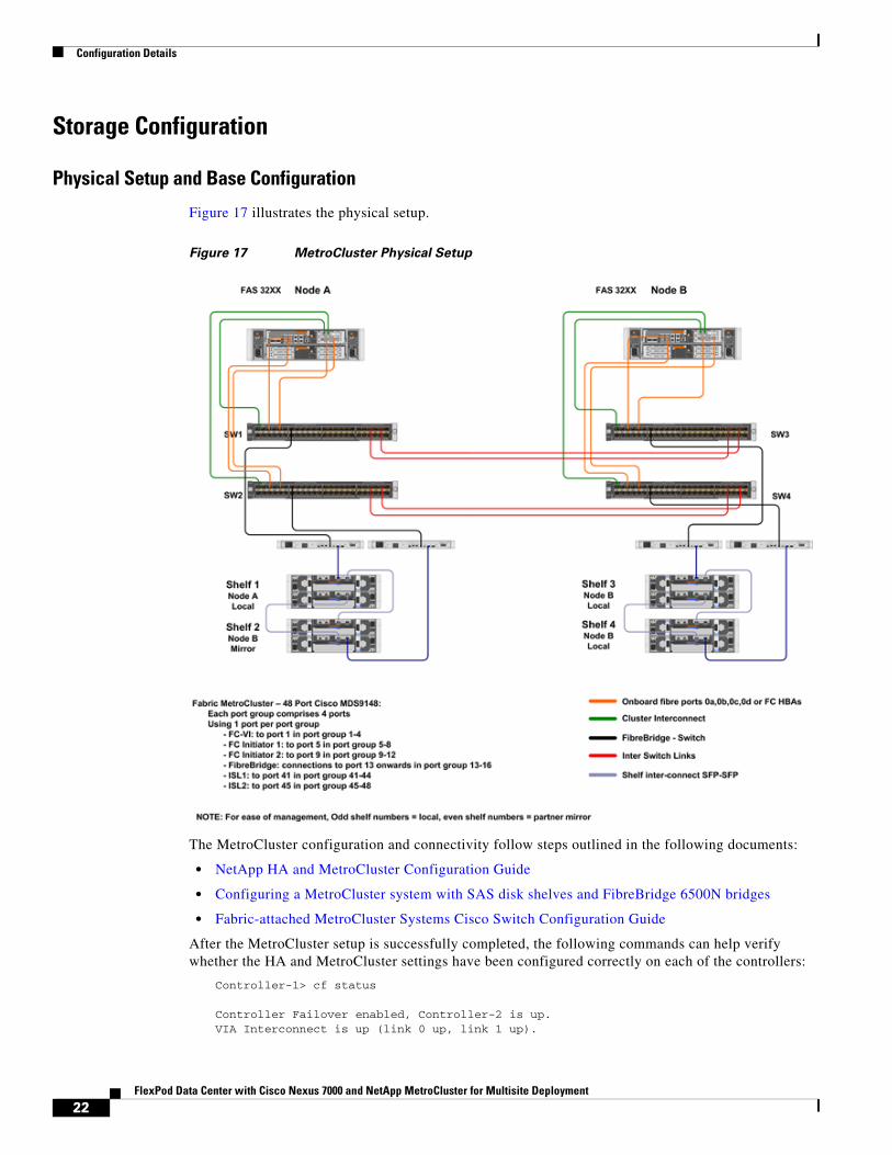
Figure 17 illustrates the physical setup.
Figure 17 MetroCluster Physical Setup
The MetroCluster configuration and connectivity follow steps outlined in the following documents:
• NetApp HA and MetroCluster Configuration Guide
• Configuring a MetroCluster system with SAS disk shelves and FibreBridge 6500N bridges
• Fabric-attached MetroCluster Systems Cisco Switch Configuration Guide
After the MetroCluster setup is successfully completed, the following commands can help verify whether the HA and MetroCluster settings have been configured correctly on each of the controllers:
Controller-1> cf status
Controller Failover enabled, Controller-2 is up.VIA Interconnect is up (link 0 up, link 1 up).
22FlexPod Data Center with Cisco Nexus 7000 and NetApp MetroCluster for Multisite Deployment
Configuration Details
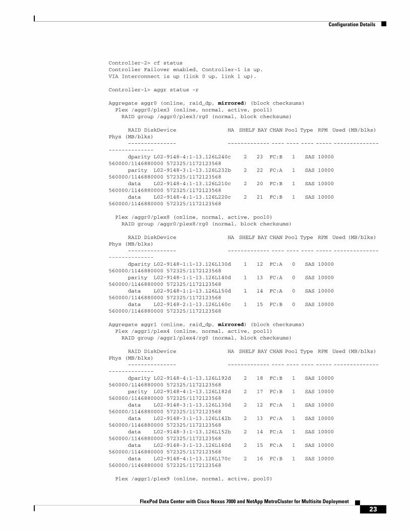
Controller-2> cf statusController Failover enabled, Controller-1 is up.VIA Interconnect is up (link 0 up, link 1 up).
Controller-1> aggr status -r
Aggregate aggr0 (online, raid_dp, mirrored) (block checksums) Plex /aggr0/plex3 (online, normal, active, pool1) RAID group /aggr0/plex3/rg0 (normal, block checksums)
RAID DiskDevice HA SHELF BAY CHAN Pool Type RPM Used (MB/blks) Phys (MB/blks) --------------- ------------- ---- ---- ---- ----- -------------- -------------- dparity L02-9148-4:1-13.126L240c 2 23 FC:B 1 SAS 10000 560000/1146880000 572325/1172123568 parity L02-9148-3:1-13.126L232b 2 22 FC:A 1 SAS 10000 560000/1146880000 572325/1172123568 data L02-9148-4:1-13.126L210c 2 20 FC:B 1 SAS 10000 560000/1146880000 572325/1172123568 data L02-9148-4:1-13.126L220c 2 21 FC:B 1 SAS 10000 560000/1146880000 572325/1172123568
Plex /aggr0/plex8 (online, normal, active, pool0) RAID group /aggr0/plex8/rg0 (normal, block checksums)
RAID DiskDevice HA SHELF BAY CHAN Pool Type RPM Used (MB/blks) Phys (MB/blks) --------------- ------------- ---- ---- ---- ----- -------------- -------------- dparity L02-9148-1:1-13.126L130d 1 12 FC:A 0 SAS 10000 560000/1146880000 572325/1172123568 parity L02-9148-1:1-13.126L140d 1 13 FC:A 0 SAS 10000 560000/1146880000 572325/1172123568 data L02-9148-1:1-13.126L150d 1 14 FC:A 0 SAS 10000 560000/1146880000 572325/1172123568 data L02-9148-2:1-13.126L160c 1 15 FC:B 0 SAS 10000 560000/1146880000 572325/1172123568
Aggregate aggr1 (online, raid_dp, mirrored) (block checksums) Plex /aggr1/plex4 (online, normal, active, pool1) RAID group /aggr1/plex4/rg0 (normal, block checksums)
RAID DiskDevice HA SHELF BAY CHAN Pool Type RPM Used (MB/blks) Phys (MB/blks) --------------- ------------- ---- ---- ---- ----- -------------- -------------- dparity L02-9148-4:1-13.126L192d 2 18 FC:B 1 SAS 10000 560000/1146880000 572325/1172123568 parity L02-9148-4:1-13.126L182d 2 17 FC:B 1 SAS 10000 560000/1146880000 572325/1172123568 data L02-9148-3:1-13.126L130d 2 12 FC:A 1 SAS 10000 560000/1146880000 572325/1172123568 data L02-9148-3:1-13.126L142b 2 13 FC:A 1 SAS 10000 560000/1146880000 572325/1172123568 data L02-9148-3:1-13.126L152b 2 14 FC:A 1 SAS 10000 560000/1146880000 572325/1172123568 data L02-9148-3:1-13.126L160d 2 15 FC:A 1 SAS 10000 560000/1146880000 572325/1172123568 data L02-9148-4:1-13.126L170c 2 16 FC:B 1 SAS 10000 560000/1146880000 572325/1172123568
Plex /aggr1/plex9 (online, normal, active, pool0)
23FlexPod Data Center with Cisco Nexus 7000 and NetApp MetroCluster for Multisite Deployment
Configuration Details
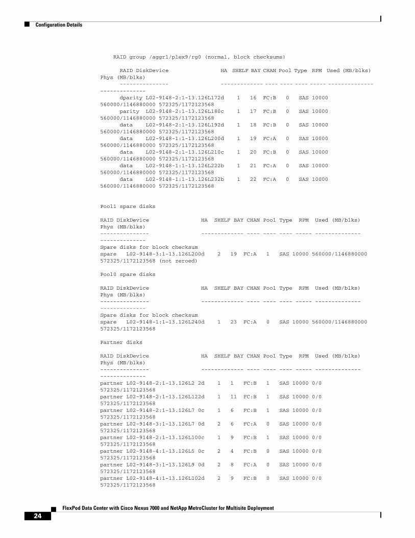
RAID group /aggr1/plex9/rg0 (normal, block checksums)
RAID DiskDevice HA SHELF BAY CHAN Pool Type RPM Used (MB/blks) Phys (MB/blks) --------------- ------------- ---- ---- ---- ----- -------------- -------------- dparity L02-9148-2:1-13.126L172d 1 16 FC:B 0 SAS 10000 560000/1146880000 572325/1172123568 parity L02-9148-2:1-13.126L180c 1 17 FC:B 0 SAS 10000 560000/1146880000 572325/1172123568 data L02-9148-2:1-13.126L192d 1 18 FC:B 0 SAS 10000 560000/1146880000 572325/1172123568 data L02-9148-1:1-13.126L200d 1 19 FC:A 0 SAS 10000 560000/1146880000 572325/1172123568 data L02-9148-2:1-13.126L210c 1 20 FC:B 0 SAS 10000 560000/1146880000 572325/1172123568 data L02-9148-1:1-13.126L222b 1 21 FC:A 0 SAS 10000 560000/1146880000 572325/1172123568 data L02-9148-1:1-13.126L232b 1 22 FC:A 0 SAS 10000 560000/1146880000 572325/1172123568
Pool1 spare disks
RAID DiskDevice HA SHELF BAY CHAN Pool Type RPM Used (MB/blks) Phys (MB/blks)--------------- ------------- ---- ---- ---- ----- -------------- --------------Spare disks for block checksumspare L02-9148-3:1-13.126L200d 2 19 FC:A 1 SAS 10000 560000/1146880000 572325/1172123568 (not zeroed)
Pool0 spare disks
RAID DiskDevice HA SHELF BAY CHAN Pool Type RPM Used (MB/blks) Phys (MB/blks)--------------- ------------- ---- ---- ---- ----- -------------- --------------Spare disks for block checksumspare L02-9148-1:1-13.126L240d 1 23 FC:A 0 SAS 10000 560000/1146880000 572325/1172123568
Partner disks
RAID DiskDevice HA SHELF BAY CHAN Pool Type RPM Used (MB/blks) Phys (MB/blks)--------------- ------------- ---- ---- ---- ----- -------------- --------------partner L02-9148-2:1-13.126L2 2d 1 1 FC:B 1 SAS 10000 0/0 572325/1172123568partner L02-9148-2:1-13.126L122d 1 11 FC:B 1 SAS 10000 0/0 572325/1172123568partner L02-9148-2:1-13.126L7 0c 1 6 FC:B 1 SAS 10000 0/0 572325/1172123568partner L02-9148-3:1-13.126L7 0d 2 6 FC:A 0 SAS 10000 0/0 572325/1172123568partner L02-9148-2:1-13.126L100c 1 9 FC:B 1 SAS 10000 0/0 572325/1172123568partner L02-9148-4:1-13.126L5 0c 2 4 FC:B 0 SAS 10000 0/0 572325/1172123568partner L02-9148-3:1-13.126L9 0d 2 8 FC:A 0 SAS 10000 0/0 572325/1172123568partner L02-9148-4:1-13.126L102d 2 9 FC:B 0 SAS 10000 0/0 572325/1172123568
24FlexPod Data Center with Cisco Nexus 7000 and NetApp MetroCluster for Multisite Deployment
Configuration Details
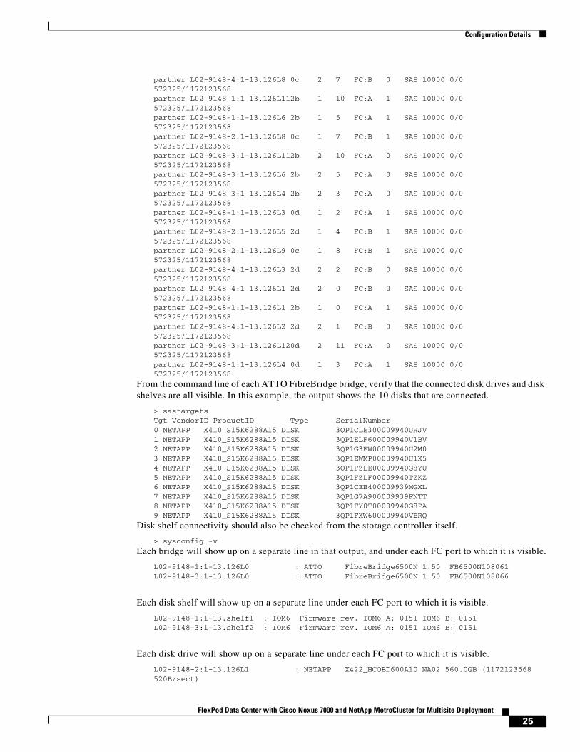
partner L02-9148-4:1-13.126L8 0c 2 7 FC:B 0 SAS 10000 0/0 572325/1172123568partner L02-9148-1:1-13.126L112b 1 10 FC:A 1 SAS 10000 0/0 572325/1172123568partner L02-9148-1:1-13.126L6 2b 1 5 FC:A 1 SAS 10000 0/0 572325/1172123568partner L02-9148-2:1-13.126L8 0c 1 7 FC:B 1 SAS 10000 0/0 572325/1172123568partner L02-9148-3:1-13.126L112b 2 10 FC:A 0 SAS 10000 0/0 572325/1172123568partner L02-9148-3:1-13.126L6 2b 2 5 FC:A 0 SAS 10000 0/0 572325/1172123568partner L02-9148-3:1-13.126L4 2b 2 3 FC:A 0 SAS 10000 0/0 572325/1172123568partner L02-9148-1:1-13.126L3 0d 1 2 FC:A 1 SAS 10000 0/0 572325/1172123568partner L02-9148-2:1-13.126L5 2d 1 4 FC:B 1 SAS 10000 0/0 572325/1172123568partner L02-9148-2:1-13.126L9 0c 1 8 FC:B 1 SAS 10000 0/0 572325/1172123568partner L02-9148-4:1-13.126L3 2d 2 2 FC:B 0 SAS 10000 0/0 572325/1172123568partner L02-9148-4:1-13.126L1 2d 2 0 FC:B 0 SAS 10000 0/0 572325/1172123568partner L02-9148-1:1-13.126L1 2b 1 0 FC:A 1 SAS 10000 0/0 572325/1172123568partner L02-9148-4:1-13.126L2 2d 2 1 FC:B 0 SAS 10000 0/0 572325/1172123568partner L02-9148-3:1-13.126L120d 2 11 FC:A 0 SAS 10000 0/0 572325/1172123568partner L02-9148-1:1-13.126L4 0d 1 3 FC:A 1 SAS 10000 0/0 572325/1172123568
From the command line of each ATTO FibreBridge bridge, verify that the connected disk drives and disk shelves are all visible. In this example, the output shows the 10 disks that are connected.
> sastargetsTgt VendorID ProductID Type SerialNumber0 NETAPP X410_S15K6288A15 DISK 3QP1CLE300009940UHJV1 NETAPP X410_S15K6288A15 DISK 3QP1ELF600009940V1BV2 NETAPP X410_S15K6288A15 DISK 3QP1G3EW00009940U2M03 NETAPP X410_S15K6288A15 DISK 3QP1EWMP00009940U1X54 NETAPP X410_S15K6288A15 DISK 3QP1FZLE00009940G8YU5 NETAPP X410_S15K6288A15 DISK 3QP1FZLF00009940TZKZ6 NETAPP X410_S15K6288A15 DISK 3QP1CEB400009939MGXL7 NETAPP X410_S15K6288A15 DISK 3QP1G7A900009939FNTT8 NETAPP X410_S15K6288A15 DISK 3QP1FY0T00009940G8PA9 NETAPP X410_S15K6288A15 DISK 3QP1FXW600009940VERQ
Disk shelf connectivity should also be checked from the storage controller itself.
> sysconfig -v
Each bridge will show up on a separate line in that output, and under each FC port to which it is visible.
L02-9148-1:1-13.126L0 : ATTO FibreBridge6500N 1.50 FB6500N108061L02-9148-3:1-13.126L0 : ATTO FibreBridge6500N 1.50 FB6500N108066
Each disk shelf will show up on a separate line under each FC port to which it is visible.
L02-9148-1:1-13.shelf1 : IOM6 Firmware rev. IOM6 A: 0151 IOM6 B: 0151L02-9148-3:1-13.shelf2 : IOM6 Firmware rev. IOM6 A: 0151 IOM6 B: 0151
Each disk drive will show up on a separate line under each FC port to which it is visible.
L02-9148-2:1-13.126L1 : NETAPP X422_HCOBD600A10 NA02 560.0GB (1172123568 520B/sect)
25FlexPod Data Center with Cisco Nexus 7000 and NetApp MetroCluster for Multisite Deployment

Configuration Details
L02-9148-2:1-13.126L2 : NETAPP X422_HCOBD600A10 NA02 560.0GB (1172123568 520B/sect)<snip>
Validation on MDS
The following commands can be issued on the MDS switches to validate the connectivity and configuration.
L02-9148-1# show zoneset activezoneset name fabric1_zoneset10 vsan 10 zone name fcvi_zone_1_3_10 vsan 10 * fcid 0xd40100 [interface fc1/1 swwn 20:00:54:7f:ee:cb:1a:78] * fcid 0x2a0100 [interface fc1/1 swwn 20:00:54:7f:ee:c1:2d:b0]
zone name $default_zone$ vsan 10
zoneset name fabric1_zoneset20 vsan 20 zone name storage_zone_5_9 vsan 20 * fcid 0xc20200 [interface fc1/5 swwn 20:00:54:7f:ee:cb:1a:78] * fcid 0x720100 [interface fc1/5 swwn 20:00:54:7f:ee:c1:2d:b0] * fcid 0x720000 [interface fc1/9 swwn 20:00:54:7f:ee:c1:2d:b0] * fcid 0xc20100 [interface fc1/9 swwn 20:00:54:7f:ee:cb:1a:78] * fcid 0x720200 [interface fc1/13 swwn 20:00:54:7f:ee:c1:2d:b0] * fcid 0xc20000 [interface fc1/13 swwn 20:00:54:7f:ee:cb:1a:78]
zone name $default_zone$ vsan 20
L02-9148-1# show fcs database vsan 10
FCS Local Database in VSAN: 10------------------------------Switch WWN : 20:0a:54:7f:ee:cb:1a:79Switch Domain Id : 0xd4(212)Switch Mgmt-Addresses : http://172.26.164.134/eth-ip snmp://172.26.164.134/eth-ipFabric-Name : 20:0a:54:7f:ee:c1:2d:b1Switch Logical-Name : L02-9148-1Switch Information List : [Cisco Systems, Inc.*DS-C9148-16P-K9*5.0(1a)*20:00:54:7f:ee:cb:1a:78]Switch Ports:-------------------------------------------------------------------Interface fWWN Type Attached-pWWNs (Device-alias)-------------------------------------------------------------------fc1/1 20:01:54:7f:ee:cb:1a:78 F 21:00:00:24:ff:52:f8:96fc1/41 20:29:54:7f:ee:cb:1a:78 TE 20:29:54:7f:ee:c1:2d:b0fc1/45 20:2d:54:7f:ee:cb:1a:78 TE 20:2d:54:7f:ee:c1:2d:b0
L02-9148-1# show fcs database vsan 20
FCS Local Database in VSAN: 20------------------------------Switch WWN : 20:14:54:7f:ee:cb:1a:79Switch Domain Id : 0xc2(194)Switch Mgmt-Addresses : http://172.26.164.134/eth-ip snmp://172.26.164.134/eth-ipFabric-Name : 20:14:54:7f:ee:c1:2d:b1Switch Logical-Name : L02-9148-1Switch Information List : [Cisco Systems, Inc.*DS-C9148-16P-K9*5.0(1a)*20:00:54:7f:ee:cb:1a:78]
26FlexPod Data Center with Cisco Nexus 7000 and NetApp MetroCluster for Multisite Deployment
Configuration Details
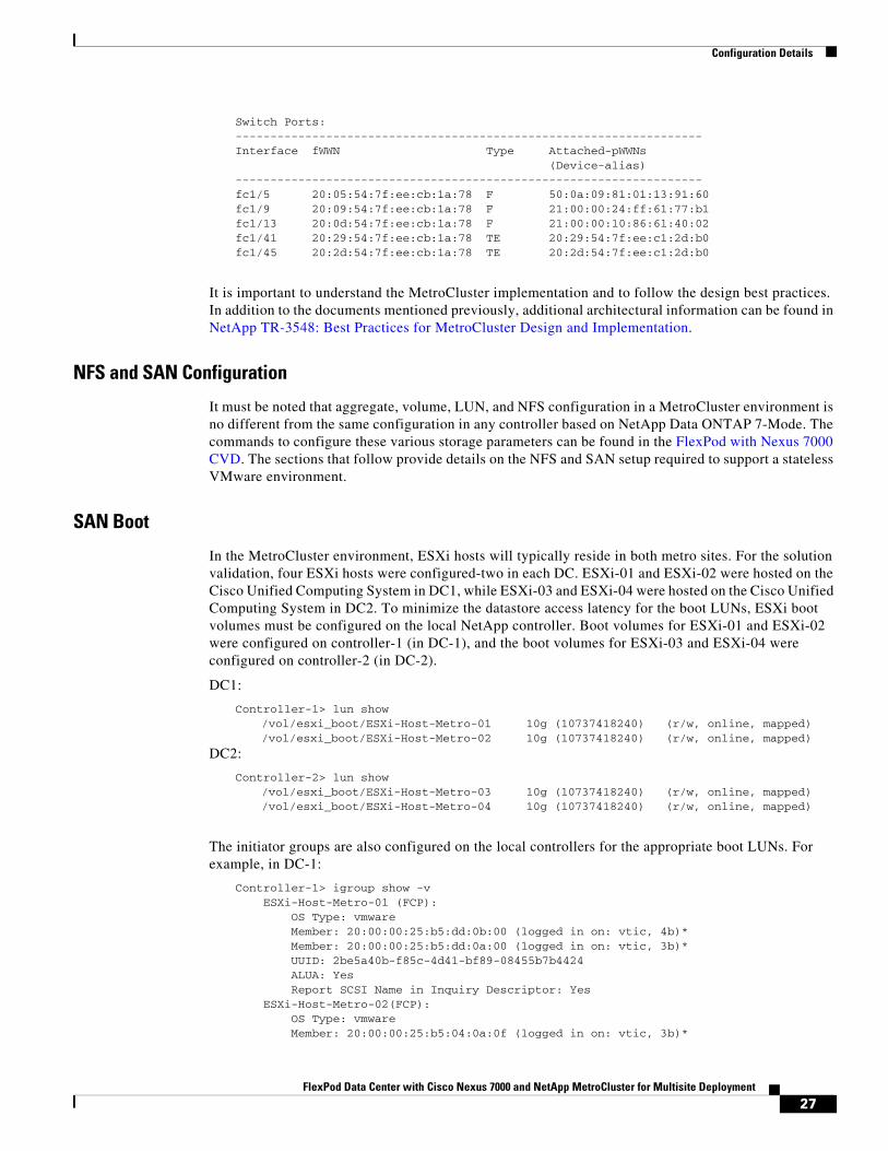
Switch Ports:-------------------------------------------------------------------Interface fWWN Type Attached-pWWNs (Device-alias)-------------------------------------------------------------------fc1/5 20:05:54:7f:ee:cb:1a:78 F 50:0a:09:81:01:13:91:60fc1/9 20:09:54:7f:ee:cb:1a:78 F 21:00:00:24:ff:61:77:b1fc1/13 20:0d:54:7f:ee:cb:1a:78 F 21:00:00:10:86:61:40:02fc1/41 20:29:54:7f:ee:cb:1a:78 TE 20:29:54:7f:ee:c1:2d:b0fc1/45 20:2d:54:7f:ee:cb:1a:78 TE 20:2d:54:7f:ee:c1:2d:b0
It is important to understand the MetroCluster implementation and to follow the design best practices. In addition to the documents mentioned previously, additional architectural information can be found in NetApp TR-3548: Best Practices for MetroCluster Design and Implementation.
NFS and SAN Configuration
It must be noted that aggregate, volume, LUN, and NFS configuration in a MetroCluster environment is no different from the same configuration in any controller based on NetApp Data ONTAP 7-Mode. The commands to configure these various storage parameters can be found in the FlexPod with Nexus 7000 CVD. The sections that follow provide details on the NFS and SAN setup required to support a stateless VMware environment.
SAN Boot
In the MetroCluster environment, ESXi hosts will typically reside in both metro sites. For the solution validation, four ESXi hosts were configured-two in each DC. ESXi-01 and ESXi-02 were hosted on the Cisco Unified Computing System in DC1, while ESXi-03 and ESXi-04 were hosted on the Cisco Unified Computing System in DC2. To minimize the datastore access latency for the boot LUNs, ESXi boot volumes must be configured on the local NetApp controller. Boot volumes for ESXi-01 and ESXi-02 were configured on controller-1 (in DC-1), and the boot volumes for ESXi-03 and ESXi-04 were configured on controller-2 (in DC-2).
DC1:
Controller-1> lun show/vol/esxi_boot/ESXi-Host-Metro-01 10g (10737418240) (r/w, online, mapped)/vol/esxi_boot/ESXi-Host-Metro-02 10g (10737418240) (r/w, online, mapped)
DC2:
Controller-2> lun show/vol/esxi_boot/ESXi-Host-Metro-03 10g (10737418240) (r/w, online, mapped)/vol/esxi_boot/ESXi-Host-Metro-04 10g (10737418240) (r/w, online, mapped)
The initiator groups are also configured on the local controllers for the appropriate boot LUNs. For example, in DC-1:
Controller-1> igroup show -v ESXi-Host-Metro-01 (FCP): OS Type: vmware Member: 20:00:00:25:b5:dd:0b:00 (logged in on: vtic, 4b)* Member: 20:00:00:25:b5:dd:0a:00 (logged in on: vtic, 3b)* UUID: 2be5a40b-f85c-4d41-bf89-08455b7b4424 ALUA: Yes Report SCSI Name in Inquiry Descriptor: Yes ESXi-Host-Metro-02(FCP): OS Type: vmware Member: 20:00:00:25:b5:04:0a:0f (logged in on: vtic, 3b)*
27FlexPod Data Center with Cisco Nexus 7000 and NetApp MetroCluster for Multisite Deployment
Configuration Details
Member: 20:00:00:25:b5:04:0b:0f (logged in on: vtic, 4b)* UUID: d02d1ae1-d799-11e2-bfbb-123478563412 ALUA: Yes Report SCSI Name in Inquiry Descriptor: Yes
* The logged-in information will only be visible when SAN and Hosts on UCS are properly configured and are able to talk to the NetApp Controllers
Under normal operations, ESXi hosts access the SAN using the local controller. In case of a failure, ESXi hosts can communicate across the WAN to access their disks. The FCoE links between the Cisco Nexus 7000 storage VDCs make this SAN connectivity over WAN possible.
NFS Datastores
NFS datastores are configured on both sites, and virtual machines (VMs) are hosted locally to avoid WAN access latency. VMware recommends configuring two datastores and creating a storage cluster for hosting the VM. In this CVD, a single datastore on each site was utilized. As covered in the FlexPod CVD, a SWAP volume was also configured in each DC to be used in the ESXi setup. The sizes of these volumes are 500GB and 100GB, respectively.
On DC1
Controller-1> vol status *
infra_datastore_1 online raid_dp, flex guarantee=none, fractional_reserve=0 mirrored sis 64-bit
infra_swap online raid_dp, flex guarantee=none, fractional_reserve=0 mirrored 64-bit
Controller-1> vol size infra_datastore_1vol size: Flexible volume 'infra_datastore_1' has size 500g.
Controller-2> vol size infra_swapvol size: Flexible volume 'infra_swap' has size 100g.
* Only the status of the relevant volumes is shown
On DC2
Controller-2> vol status * Volume State Status Options
infra_datastore_2 online raid_dp, flex guarantee=none, fractional_reserve=0 mirrored sis 64-bit
infra_swap online raid_dp, flex guarantee=none, fractional_reserve=0 mirrored 64-bit
Controller-2> vol size infra_datastore_1vol size: Flexible volume 'infra_datastore_1' has size 500g.
Controller-2> vol size infra_swap
28FlexPod Data Center with Cisco Nexus 7000 and NetApp MetroCluster for Multisite Deployment
Configuration Details
vol size: Flexible volume 'infra_swap' has size 100g.
* Only the status of the relevant volumes is shown
For the NFS volumes shown previously, NFS exports need to be configured as described in this CVD.
Server (UCS) ConfigurationThis section provides details for configuring the Cisco Unified Computing System (UCS) for use in a multisite FlexPod environment. The detailed steps necessary to provision the Cisco UCS servers are defined in the Nexus 7000 based FlexPod CVD. In this deployment guide, changes or additional configurations are provided in the following sections.
Multiple Cisco UCS Domains
As seen in Figure 6, a multisite FlexPod configuration consists of two UCS domains: domain-1 in DC1 and domain-2 in DC2. Each of these domains is configured exactly the same, as shown in the Cisco Nexus 7000 based CVD with minor modifications in some of the configuration parameters. The parameters that need to be unique across the two domains are:
• IP pools for management
• UUID suffix pools
• MAC address pools
• WWNN pools
• WWPN pools
• Boot policies (covered in the next section)
• Boot from SAN Policies
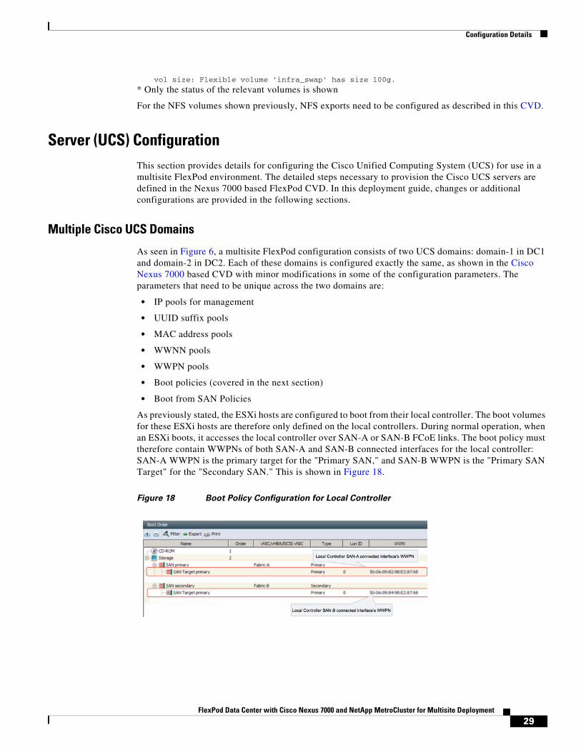
As previously stated, the ESXi hosts are configured to boot from their local controller. The boot volumes for these ESXi hosts are therefore only defined on the local controllers. During normal operation, when an ESXi boots, it accesses the local controller over SAN-A or SAN-B FCoE links. The boot policy must therefore contain WWPNs of both SAN-A and SAN-B connected interfaces for the local controller: SAN-A WWPN is the primary target for the "Primary SAN," and SAN-B WWPN is the "Primary SAN Target" for the "Secondary SAN." This is shown in Figure 18.
Figure 18 Boot Policy Configuration for Local Controller
29FlexPod Data Center with Cisco Nexus 7000 and NetApp MetroCluster for Multisite Deployment
Configuration Details
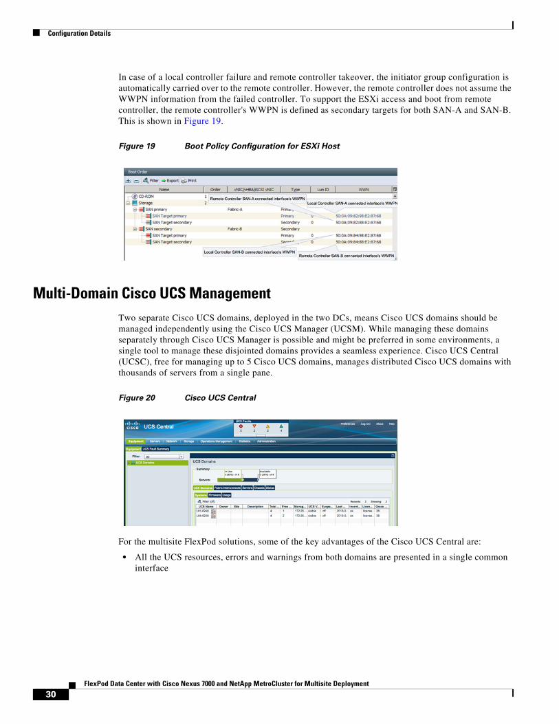
In case of a local controller failure and remote controller takeover, the initiator group configuration is automatically carried over to the remote controller. However, the remote controller does not assume the WWPN information from the failed controller. To support the ESXi access and boot from remote controller, the remote controller's WWPN is defined as secondary targets for both SAN-A and SAN-B. This is shown in Figure 19.
Figure 19 Boot Policy Configuration for ESXi Host
Multi-Domain Cisco UCS ManagementTwo separate Cisco UCS domains, deployed in the two DCs, means Cisco UCS domains should be managed independently using the Cisco UCS Manager (UCSM). While managing these domains separately through Cisco UCS Manager is possible and might be preferred in some environments, a single tool to manage these disjointed domains provides a seamless experience. Cisco UCS Central (UCSC), free for managing up to 5 Cisco UCS domains, manages distributed Cisco UCS domains with thousands of servers from a single pane.
Figure 20 Cisco UCS Central
For the multisite FlexPod solutions, some of the key advantages of the Cisco UCS Central are:
• All the UCS resources, errors and warnings from both domains are presented in a single common interface
30FlexPod Data Center with Cisco Nexus 7000 and NetApp MetroCluster for Multisite Deployment
Configuration Details
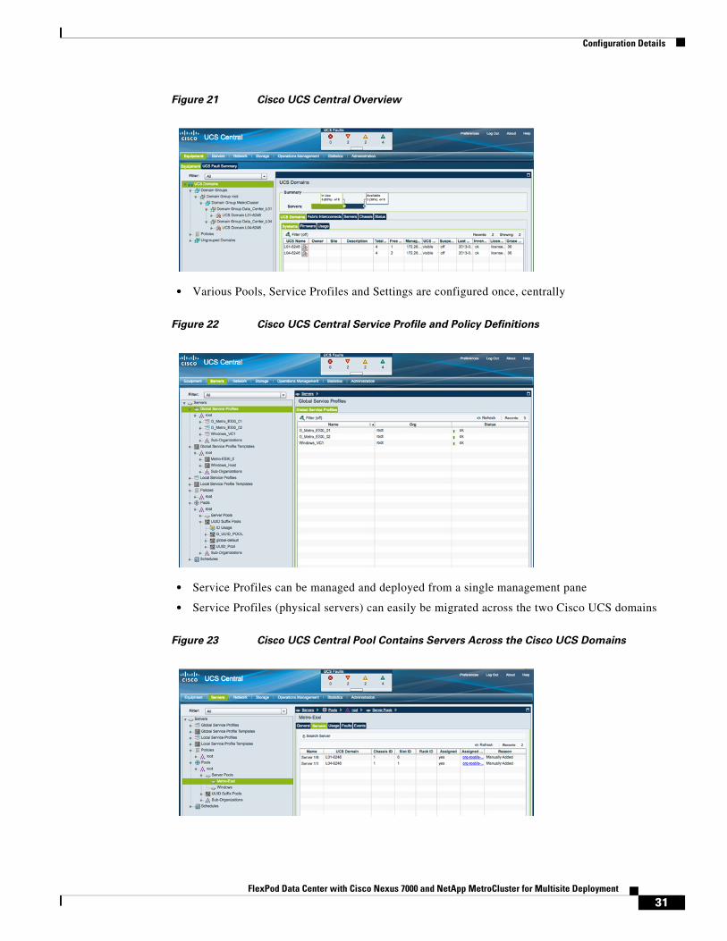
Figure 21 Cisco UCS Central Overview
• Various Pools, Service Profiles and Settings are configured once, centrally
Figure 22 Cisco UCS Central Service Profile and Policy Definitions
• Service Profiles can be managed and deployed from a single management pane
• Service Profiles (physical servers) can easily be migrated across the two Cisco UCS domains
Figure 23 Cisco UCS Central Pool Contains Servers Across the Cisco UCS Domains
31FlexPod Data Center with Cisco Nexus 7000 and NetApp MetroCluster for Multisite Deployment
Configuration Details
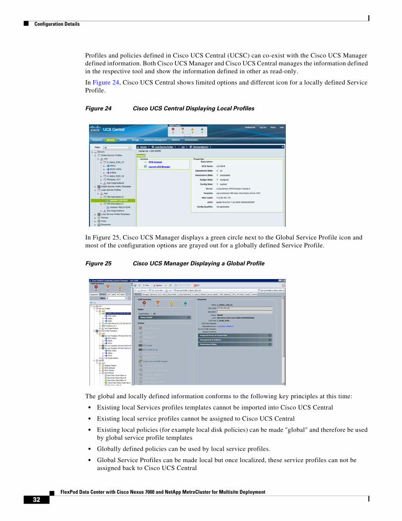
Profiles and policies defined in Cisco UCS Central (UCSC) can co-exist with the Cisco UCS Manager defined information. Both Cisco UCS Manager and Cisco UCS Central manages the information defined in the respective tool and show the information defined in other as read-only.
In Figure 24, Cisco UCS Central shows limited options and different icon for a locally defined Service Profile.
Figure 24 Cisco UCS Central Displaying Local Profiles
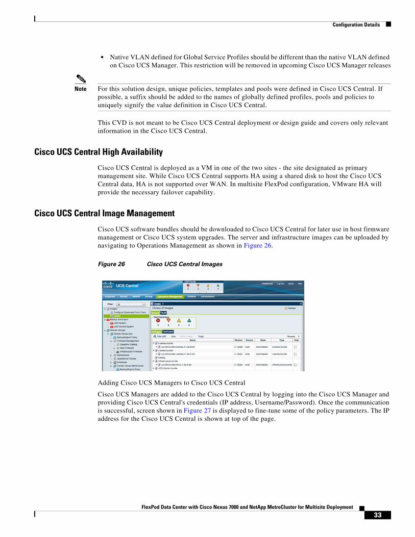
In Figure 25, Cisco UCS Manager displays a green circle next to the Global Service Profile icon and most of the configuration options are grayed out for a globally defined Service Profile.
Figure 25 Cisco UCS Manager Displaying a Global Profile
The global and locally defined information conforms to the following key principles at this time:
• Existing local Services profiles templates cannot be imported into Cisco UCS Central
• Existing local service profiles cannot be assigned to Cisco UCS Central
• Existing local policies (for example local disk policies) can be made "global" and therefore be used by global service profile templates
• Globally defined policies can be used by local service profiles.
• Global Service Profiles can be made local but once localized, these service profiles can not be assigned back to Cisco UCS Central
32FlexPod Data Center with Cisco Nexus 7000 and NetApp MetroCluster for Multisite Deployment
Configuration Details
• Native VLAN defined for Global Service Profiles should be different than the native VLAN defined on Cisco UCS Manager. This restriction will be removed in upcoming Cisco UCS Manager releases
Note For this solution design, unique policies, templates and pools were defined in Cisco UCS Central. If possible, a suffix should be added to the names of globally defined profiles, pools and policies to uniquely signify the value definition in Cisco UCS Central.
This CVD is not meant to be Cisco UCS Central deployment or design guide and covers only relevant information in the Cisco UCS Central.
Cisco UCS Central High Availability
Cisco UCS Central is deployed as a VM in one of the two sites - the site designated as primary management site. While Cisco UCS Central supports HA using a shared disk to host the Cisco UCS Central data, HA is not supported over WAN. In multisite FlexPod configuration, VMware HA will provide the necessary failover capability.
Cisco UCS Central Image Management
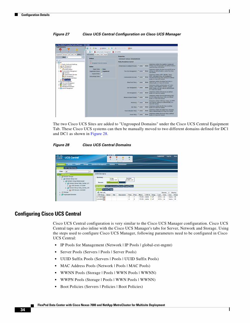
Cisco UCS software bundles should be downloaded to Cisco UCS Central for later use in host firmware management or Cisco UCS system upgrades. The server and infrastructure images can be uploaded by navigating to Operations Management as shown in Figure 26.
Figure 26 Cisco UCS Central Images
Adding Cisco UCS Managers to Cisco UCS Central
Cisco UCS Managers are added to the Cisco UCS Central by logging into the Cisco UCS Manager and providing Cisco UCS Central's credentials (IP address, Username/Password). Once the communication is successful, screen shown in Figure 27 is displayed to fine-tune some of the policy parameters. The IP address for the Cisco UCS Central is shown at top of the page.
33FlexPod Data Center with Cisco Nexus 7000 and NetApp MetroCluster for Multisite Deployment
Configuration Details
Figure 27 Cisco UCS Central Configuration on Cisco UCS Manager
The two Cisco UCS Sites are added to "Ungrouped Domains" under the Cisco UCS Central Equipment Tab. These Cisco UCS systems can then be manually moved to two different domains defined for DC1 and DC1 as shown in Figure 28.
Figure 28 Cisco UCS Central Domains
Configuring Cisco UCS Central
Cisco UCS Central configuration is very similar to the Cisco UCS Manager configuration. Cisco UCS Central taps are also inline with the Cisco UCS Manager's tabs for Server, Network and Storage. Using the steps used to configure Cisco UCS Manager, following parameters need to be configured in Cisco UCS Central:
• IP Pools for Management (Network | IP Pools | global-ext-mgmt)
• Server Pools (Servers | Pools | Server Pools)
• UUID Suffix Pools (Servers | Pools | UUID Suffix Pools)
• MAC Address Pools (Network | Pools | MAC Pools)
• WWNN Pools (Storage | Pools | WWN Pools | WWNN)
• WWPN Pools (Storage | Pools | WWN Pools | WWNN)
• Boot Policies (Servers | Policies | Boot Policies)
34FlexPod Data Center with Cisco Nexus 7000 and NetApp MetroCluster for Multisite Deployment
Configuration Details
• BIOS Policy (Servers | Policies | BIOS Policies)
• Host Firmware Policy (Servers | Policies | Host Firmware Packages)
• Power Control Policy (Servers | Policies | Power Control Policies)
• vNIC/vHBA Placement Policy (Servers | Policies | vNIC/vHBA Placement Policies)
• vNIC Template (Network | Policies | vNIC Templates)
• vHBA Template (Storage | Policies | vHBA Templates)
• Service Profile Templates (Servers | Global Service Profile Templates)
With all the configurations in place, Service Profiles can be deployed on both the Cisco UCS domains from Cisco UCS Central.
Network Configuration
Nexus 7000
Cisco Nexus 7000 is configured with a separate switching and storage VDC to carry Ethernet and SAN traffic. The base configuration of various ports connection is covered in the original FlexPod CVD. The difference and additions are covered below.
Nexus 7000 - Storage VDC
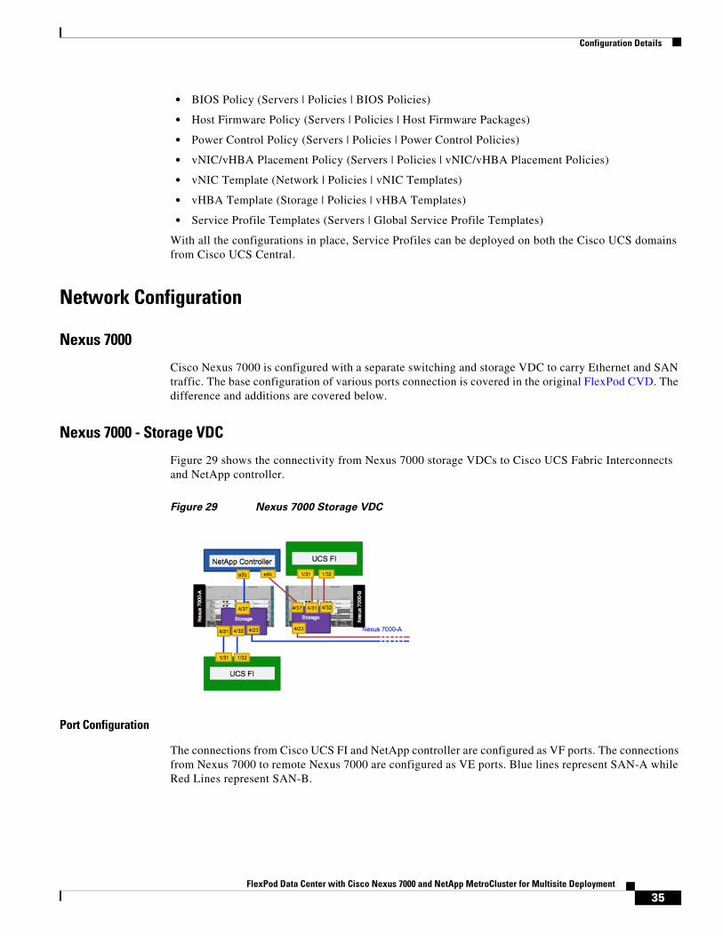
Figure 29 shows the connectivity from Nexus 7000 storage VDCs to Cisco UCS Fabric Interconnects and NetApp controller.
Figure 29 Nexus 7000 Storage VDC
Port Configuration
The connections from Cisco UCS FI and NetApp controller are configured as VF ports. The connections from Nexus 7000 to remote Nexus 7000 are configured as VE ports. Blue lines represent SAN-A while Red Lines represent SAN-B.
35FlexPod Data Center with Cisco Nexus 7000 and NetApp MetroCluster for Multisite Deployment
Configuration Details
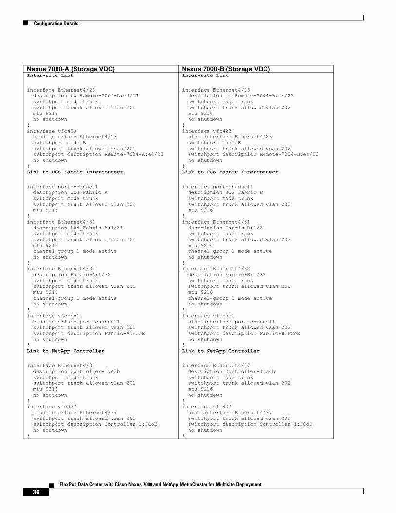
Nexus 7000-A (Storage VDC) Nexus 7000-B (Storage VDC)Inter-site Link
interface Ethernet4/23 description to Remote-7004-A:e4/23 switchport mode trunk switchport trunk allowed vlan 201 mtu 9216 no shutdown!interface vfc423 bind interface Ethernet4/23 switchport mode E switchport trunk allowed vsan 201 switchport description Remote-7004-A:e4/23 no shutdown!Link to UCS Fabric Interconnect
interface port-channel1 description UCS Fabric A switchport mode trunk switchport trunk allowed vlan 201 mtu 9216!interface Ethernet4/31 description L04_Fabric-A:1/31 switchport mode trunk switchport trunk allowed vlan 201 mtu 9216 channel-group 1 mode active no shutdown!interface Ethernet4/32 description Fabric-A:1/32 switchport mode trunk switchport trunk allowed vlan 201 mtu 9216 channel-group 1 mode active no shutdown!interface vfc-po1 bind interface port-channel1 switchport trunk allowed vsan 201 switchport description Fabric-A:FCoE no shutdown!Link to NetApp Controller
interface Ethernet4/37 description Controller-1:e3b switchport mode trunk switchport trunk allowed vlan 201 mtu 9216 no shutdown!interface vfc437 bind interface Ethernet4/37 switchport trunk allowed vsan 201 switchport description Controller-1:FCoE no shutdown!
Inter-site Link
interface Ethernet4/23 description to Remote-7004-B:e4/23 switchport mode trunk switchport trunk allowed vlan 202 mtu 9216 no shutdown!interface vfc423 bind interface Ethernet4/23 switchport mode E switchport trunk allowed vsan 202 switchport description Remote-7004-B:e4/23 no shutdown!Link to UCS Fabric Interconnect
interface port-channel1 description UCS Fabric B switchport mode trunk switchport trunk allowed vlan 202 mtu 9216!interface Ethernet4/31 description Fabric-B:1/31 switchport mode trunk switchport trunk allowed vlan 202 mtu 9216 channel-group 1 mode active no shutdown!interface Ethernet4/32 description Fabric-B:1/32 switchport mode trunk switchport trunk allowed vlan 202 mtu 9216 channel-group 1 mode active no shutdown!interface vfc-po1 bind interface port-channel1 switchport trunk allowed vsan 202 switchport description Fabric-B:FCoE no shutdown!Link to NetApp Controller
interface Ethernet4/37 description Controller-1:e4b switchport mode trunk switchport trunk allowed vlan 202 mtu 9216 no shutdown!interface vfc437 bind interface Ethernet4/37 switchport trunk allowed vsan 202 switchport description Controller-1:FCoE no shutdown!
36FlexPod Data Center with Cisco Nexus 7000 and NetApp MetroCluster for Multisite Deployment
Configuration Details
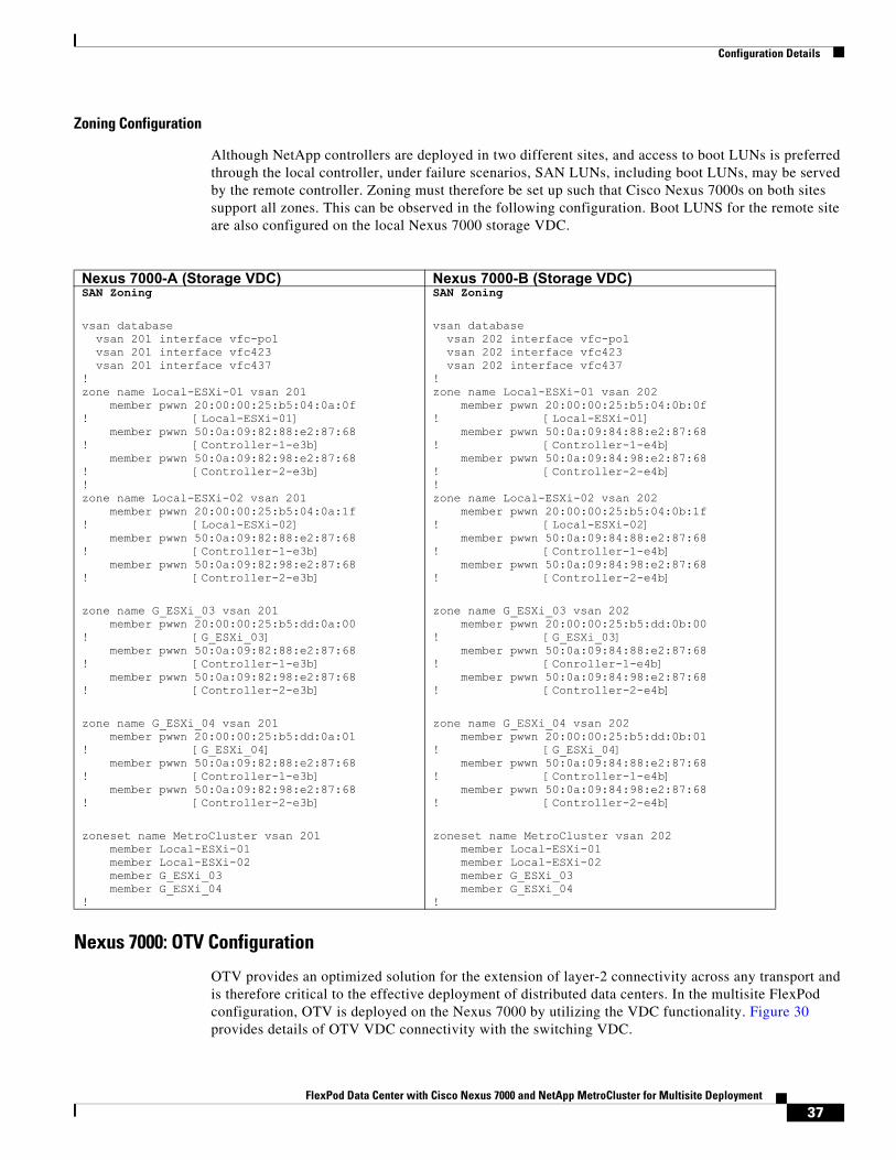
Zoning Configuration
Although NetApp controllers are deployed in two different sites, and access to boot LUNs is preferred through the local controller, under failure scenarios, SAN LUNs, including boot LUNs, may be served by the remote controller. Zoning must therefore be set up such that Cisco Nexus 7000s on both sites support all zones. This can be observed in the following configuration. Boot LUNS for the remote site are also configured on the local Nexus 7000 storage VDC.
Nexus 7000: OTV Configuration
OTV provides an optimized solution for the extension of layer-2 connectivity across any transport and is therefore critical to the effective deployment of distributed data centers. In the multisite FlexPod configuration, OTV is deployed on the Nexus 7000 by utilizing the VDC functionality. Figure 30 provides details of OTV VDC connectivity with the switching VDC.
Nexus 7000-A (Storage VDC) Nexus 7000-B (Storage VDC)SAN Zoning
vsan database vsan 201 interface vfc-po1 vsan 201 interface vfc423 vsan 201 interface vfc437!zone name Local-ESXi-01 vsan 201 member pwwn 20:00:00:25:b5:04:0a:0f! [Local-ESXi-01] member pwwn 50:0a:09:82:88:e2:87:68! [Controller-1-e3b] member pwwn 50:0a:09:82:98:e2:87:68! [Controller-2-e3b]!zone name Local-ESXi-02 vsan 201 member pwwn 20:00:00:25:b5:04:0a:1f! [Local-ESXi-02] member pwwn 50:0a:09:82:88:e2:87:68! [Controller-1-e3b] member pwwn 50:0a:09:82:98:e2:87:68! [Controller-2-e3b]
zone name G_ESXi_03 vsan 201 member pwwn 20:00:00:25:b5:dd:0a:00! [G_ESXi_03] member pwwn 50:0a:09:82:88:e2:87:68! [Controller-1-e3b] member pwwn 50:0a:09:82:98:e2:87:68! [Controller-2-e3b]
zone name G_ESXi_04 vsan 201 member pwwn 20:00:00:25:b5:dd:0a:01! [G_ESXi_04] member pwwn 50:0a:09:82:88:e2:87:68! [Controller-1-e3b] member pwwn 50:0a:09:82:98:e2:87:68! [Controller-2-e3b]
zoneset name MetroCluster vsan 201 member Local-ESXi-01 member Local-ESXi-02 member G_ESXi_03 member G_ESXi_04!
SAN Zoning
vsan database vsan 202 interface vfc-po1 vsan 202 interface vfc423 vsan 202 interface vfc437!zone name Local-ESXi-01 vsan 202 member pwwn 20:00:00:25:b5:04:0b:0f! [Local-ESXi-01] member pwwn 50:0a:09:84:88:e2:87:68! [Controller-1-e4b] member pwwn 50:0a:09:84:98:e2:87:68! [Controller-2-e4b]!zone name Local-ESXi-02 vsan 202 member pwwn 20:00:00:25:b5:04:0b:1f! [Local-ESXi-02] member pwwn 50:0a:09:84:88:e2:87:68! [Controller-1-e4b] member pwwn 50:0a:09:84:98:e2:87:68! [Controller-2-e4b]
zone name G_ESXi_03 vsan 202 member pwwn 20:00:00:25:b5:dd:0b:00! [G_ESXi_03] member pwwn 50:0a:09:84:88:e2:87:68! [Conroller-1-e4b] member pwwn 50:0a:09:84:98:e2:87:68! [Controller-2-e4b]
zone name G_ESXi_04 vsan 202 member pwwn 20:00:00:25:b5:dd:0b:01! [G_ESXi_04] member pwwn 50:0a:09:84:88:e2:87:68! [Controller-1-e4b] member pwwn 50:0a:09:84:98:e2:87:68! [Controller-2-e4b]
zoneset name MetroCluster vsan 202 member Local-ESXi-01 member Local-ESXi-02 member G_ESXi_03 member G_ESXi_04!
37FlexPod Data Center with Cisco Nexus 7000 and NetApp MetroCluster for Multisite Deployment
Configuration Details
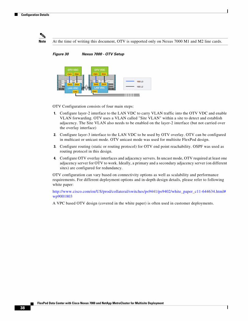
Note At the time of writing this document, OTV is supported only on Nexus 7000 M1 and M2 line cards.
Figure 30 Nexus 7000 - OTV Setup
OTV Configuration consists of four main steps:
1. Configure layer-2 interface to the LAN VDC to carry VLAN traffic into the OTV VDC and enable VLAN forwarding. OTV uses a VLAN called "Site VLAN" within a site to detect and establish adjacency. The Site VLAN also needs to be enabled on the layer-2 interface (but not carried over the overlay interface)
2. Configure layer-3 interface to the LAN VDC to be used by OTV overlay. OTV can be configured in multicast or unicast mode. OTV unicast mode was used for multisite FlexPod design.
3. Configure routing (static or routing protocol) for OTV end point reachability. OSPF was used as routing protocol in this design.
4. Configure OTV overlay interfaces and adjacency servers. In uncast mode, OTV required at least one adjacency server for OTV to work. Ideally, a primary and a secondary adjacency server (on different sites) are configured for redundancy.
OTV configuration can vary based on connectivity options as well as scalability and performance requirements. For different deployment options and in-depth design details, please refer to following white paper:
http://www.cisco.com/en/US/prod/collateral/switches/ps9441/ps9402/white_paper_c11-644634.html#wp9001803
A VPC based OTV design (covered in the white paper) is often used in customer deployments.
38FlexPod Data Center with Cisco Nexus 7000 and NetApp MetroCluster for Multisite Deployment
Configuration Details
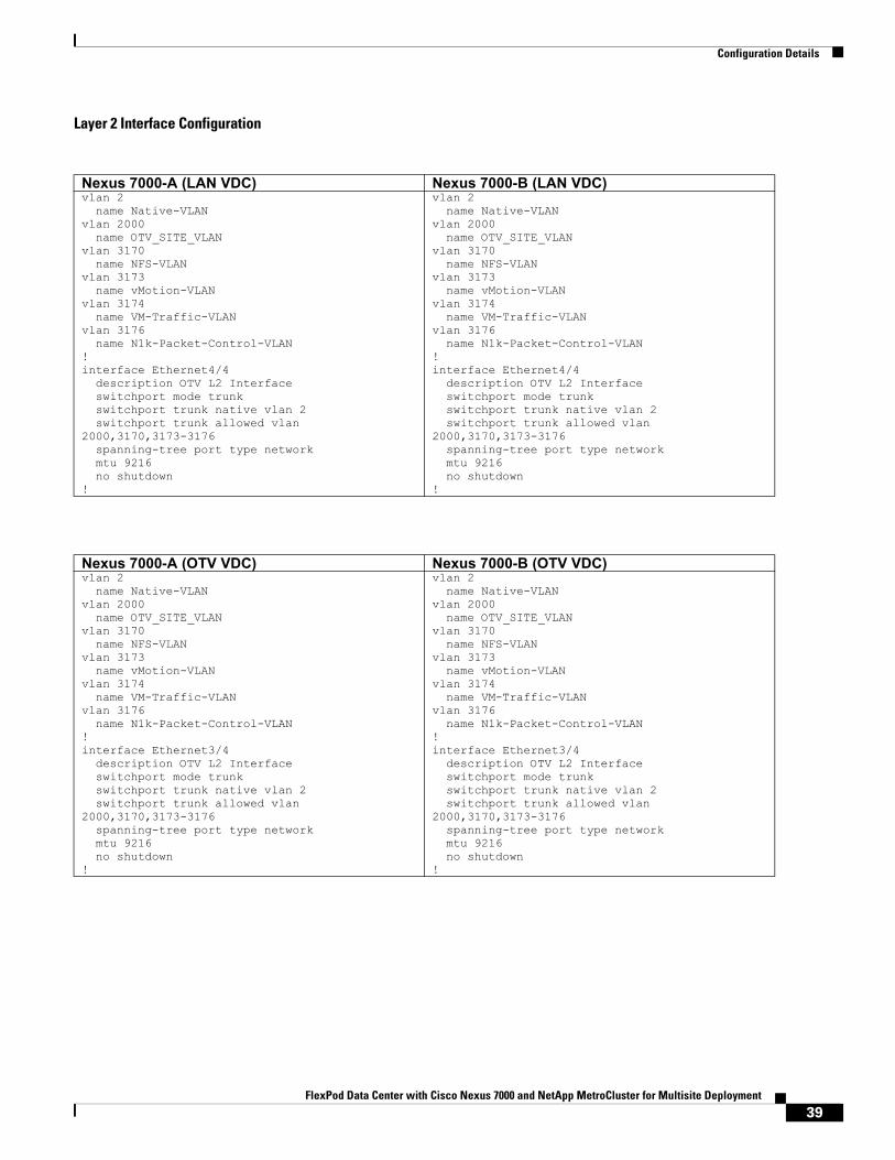
Layer 2 Interface Configuration
Nexus 7000-A (LAN VDC) Nexus 7000-B (LAN VDC)vlan 2 name Native-VLANvlan 2000 name OTV_SITE_VLANvlan 3170 name NFS-VLANvlan 3173 name vMotion-VLANvlan 3174 name VM-Traffic-VLANvlan 3176 name N1k-Packet-Control-VLAN!interface Ethernet4/4 description OTV L2 Interface switchport mode trunk switchport trunk native vlan 2 switchport trunk allowed vlan 2000,3170,3173-3176 spanning-tree port type network mtu 9216 no shutdown!
vlan 2 name Native-VLANvlan 2000 name OTV_SITE_VLANvlan 3170 name NFS-VLANvlan 3173 name vMotion-VLANvlan 3174 name VM-Traffic-VLANvlan 3176 name N1k-Packet-Control-VLAN!interface Ethernet4/4 description OTV L2 Interface switchport mode trunk switchport trunk native vlan 2 switchport trunk allowed vlan 2000,3170,3173-3176 spanning-tree port type network mtu 9216 no shutdown!
Nexus 7000-A (OTV VDC) Nexus 7000-B (OTV VDC)vlan 2 name Native-VLANvlan 2000 name OTV_SITE_VLANvlan 3170 name NFS-VLANvlan 3173 name vMotion-VLANvlan 3174 name VM-Traffic-VLANvlan 3176 name N1k-Packet-Control-VLAN!interface Ethernet3/4 description OTV L2 Interface switchport mode trunk switchport trunk native vlan 2 switchport trunk allowed vlan 2000,3170,3173-3176 spanning-tree port type network mtu 9216 no shutdown!
vlan 2 name Native-VLANvlan 2000 name OTV_SITE_VLANvlan 3170 name NFS-VLANvlan 3173 name vMotion-VLANvlan 3174 name VM-Traffic-VLANvlan 3176 name N1k-Packet-Control-VLAN!interface Ethernet3/4 description OTV L2 Interface switchport mode trunk switchport trunk native vlan 2 switchport trunk allowed vlan 2000,3170,3173-3176 spanning-tree port type network mtu 9216 no shutdown!
39FlexPod Data Center with Cisco Nexus 7000 and NetApp MetroCluster for Multisite Deployment
Configuration Details
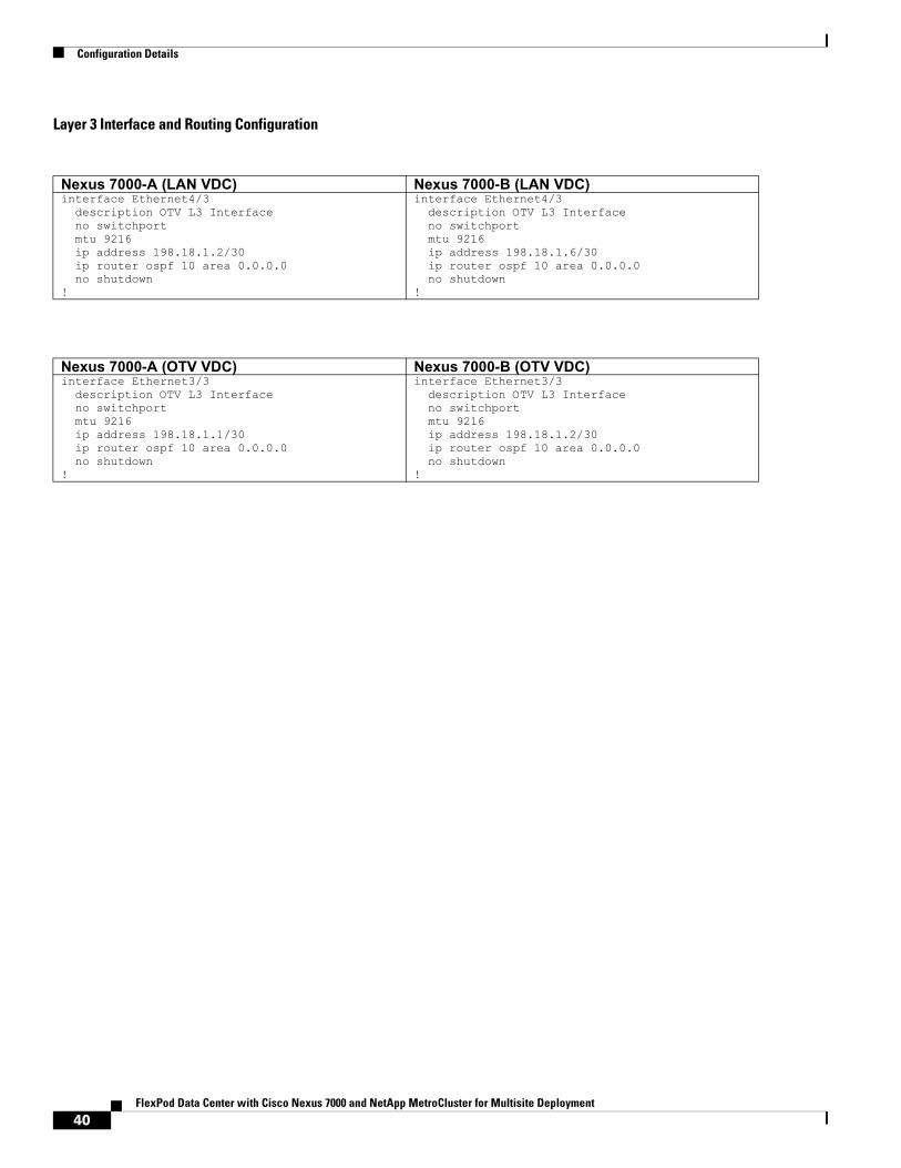
Layer 3 Interface and Routing Configuration
Nexus 7000-A (LAN VDC) Nexus 7000-B (LAN VDC)interface Ethernet4/3 description OTV L3 Interface no switchport mtu 9216 ip address 198.18.1.2/30 ip router ospf 10 area 0.0.0.0 no shutdown!
interface Ethernet4/3 description OTV L3 Interface no switchport mtu 9216 ip address 198.18.1.6/30 ip router ospf 10 area 0.0.0.0 no shutdown!
Nexus 7000-A (OTV VDC) Nexus 7000-B (OTV VDC)interface Ethernet3/3 description OTV L3 Interface no switchport mtu 9216 ip address 198.18.1.1/30 ip router ospf 10 area 0.0.0.0 no shutdown!
interface Ethernet3/3 description OTV L3 Interface no switchport mtu 9216 ip address 198.18.1.2/30 ip router ospf 10 area 0.0.0.0 no shutdown!
40FlexPod Data Center with Cisco Nexus 7000 and NetApp MetroCluster for Multisite Deployment
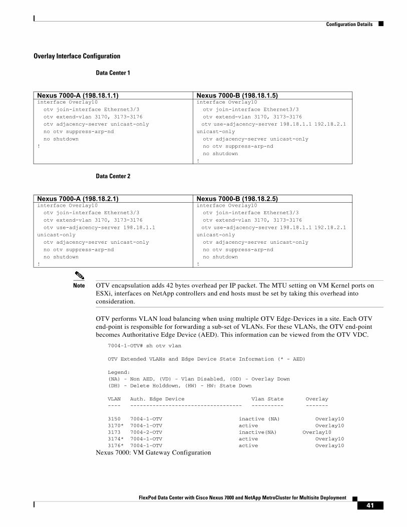
Configuration Details
Overlay Interface Configuration
Data Center 1
Data Center 2
Note OTV encapsulation adds 42 bytes overhead per IP packet. The MTU setting on VM Kernel ports on ESXi, interfaces on NetApp controllers and end hosts must be set by taking this overhead into consideration.
OTV performs VLAN load balancing when using multiple OTV Edge-Devices in a site. Each OTV end-point is responsible for forwarding a sub-set of VLANs. For these VLANs, the OTV end-point becomes Authoritative Edge Device (AED). This information can be viewed from the OTV VDC.
7004-1-OTV# sh otv vlan
OTV Extended VLANs and Edge Device State Information (* - AED)
Legend:(NA) - Non AED, (VD) - Vlan Disabled, (OD) - Overlay Down(DH) - Delete Holddown, (HW) - HW: State Down
VLAN Auth. Edge Device Vlan State Overlay---- ----------------------------------- ---------- -------
3150 7004-1-OTV inactive (NA) Overlay103170* 7004-1-OTV active Overlay103173 7004-2-OTV inactive(NA) Overlay103174* 7004-1-OTV active Overlay103176* 7004-1-OTV active Overlay10
Nexus 7000: VM Gateway Configuration
Nexus 7000-A (198.18.1.1) Nexus 7000-B (198.18.1.5)interface Overlay10 otv join-interface Ethernet3/3 otv extend-vlan 3170, 3173-3176 otv adjacency-server unicast-only no otv suppress-arp-nd no shutdown!
interface Overlay10 otv join-interface Ethernet3/3 otv extend-vlan 3170, 3173-3176 otv use-adjacency-server 198.18.1.1 192.18.2.1 unicast-only otv adjacency-server unicast-only no otv suppress-arp-nd no shutdown!
Nexus 7000-A (198.18.2.1) Nexus 7000-B (198.18.2.5)interface Overlay10 otv join-interface Ethernet3/3 otv extend-vlan 3170, 3173-3176 otv use-adjacency-server 198.18.1.1 unicast-only otv adjacency-server unicast-only no otv suppress-arp-nd no shutdown!
interface Overlay10 otv join-interface Ethernet3/3 otv extend-vlan 3170, 3173-3176 otv use-adjacency-server 198.18.1.1 192.18.2.1 unicast-only otv adjacency-server unicast-only no otv suppress-arp-nd no shutdown!
41FlexPod Data Center with Cisco Nexus 7000 and NetApp MetroCluster for Multisite Deployment
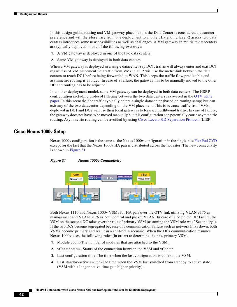
Configuration Details
In this design guide, routing and VM gateway placement in the Data Center is considered a customer preference and will therefore vary from one deployment to another. Extending layer-2 across two data centers introduces some new possibilities as well as challenges. A VM gateway in multisite datacenters are typically deployed in one of the following two ways:
1. A VM gateway is deployed in one of the two data centers
2. Same VM gateway is deployed in both data centers
When a VM gateway is deployed in a single datacenter say DC1, traffic will always enter and exit DC1 regardless of VM placement i.e. traffic from VMs in DC2 will use the metro-link between the data centers to reach DC1 before being forwarded to WAN. This keeps the traffic flow predictable and asymmetric routing is avoided. In case of a failure, the gateway has to be manually moved to the other DC and routing has to be adjusted.
In another deployment model, same VM gateway can be deployed in both data centers. The HSRP configuration including protocol filtering between the two data centers is covered in the OTV white paper. In this scenario, the traffic typically enters a single datacenter (based on routing setup) but can exit any of the two datacenter depending on the VM placement. This is because traffic from VMs deployed in DC1 and DC2 will use their local gateways to forward northbound traffic. In case of failure, the gateway does not have to be moved manually but this configuration can potentially cause asymmetric routing. Asymmetric routing can be avoided by using Cisco Locator/ID Separation Protocol (LISP).
Cisco Nexus 1000v Setup
Nexus 1000v configuration is the same as the Nexus 1000v configuration in the single-site FlexPod CVD except for the fact that the Nexus 1000v HA pair is distributed across the two sites. The new connectivity is shown in Figure 31.
Figure 31 Nexus 1000v Connectivity
Both Nexus 1110 and Nexus 1000v VSMs for HA pair over the OTV link utilizing VLAN 3175 as management and VLAN 3176 as both control and packet VLAN. In case of a complete DC failure, the VSM on the second DC takes over the role of primary VSM (assuming the VSM role was "Secondary"). If the two DCs become segregated because of a communication failure such as network links down, both VSMs become primary and result in a split-brain scenario. When the DCs communication resumes, Nexus 1000v uses the following rules (in order) to determine the new primary VSM.
1. Module count-The number of modules that are attached to the VSM.
2. vCenter status- Status of the connection between the VSM and vCenter.
3. Last configuration time-The time when the last configuration is done on the VSM.
4. Last standby-active switch-The time when the VSM last switched from standby to active state. (VSM with a longer active time gets higher priority).
42FlexPod Data Center with Cisco Nexus 7000 and NetApp MetroCluster for Multisite Deployment
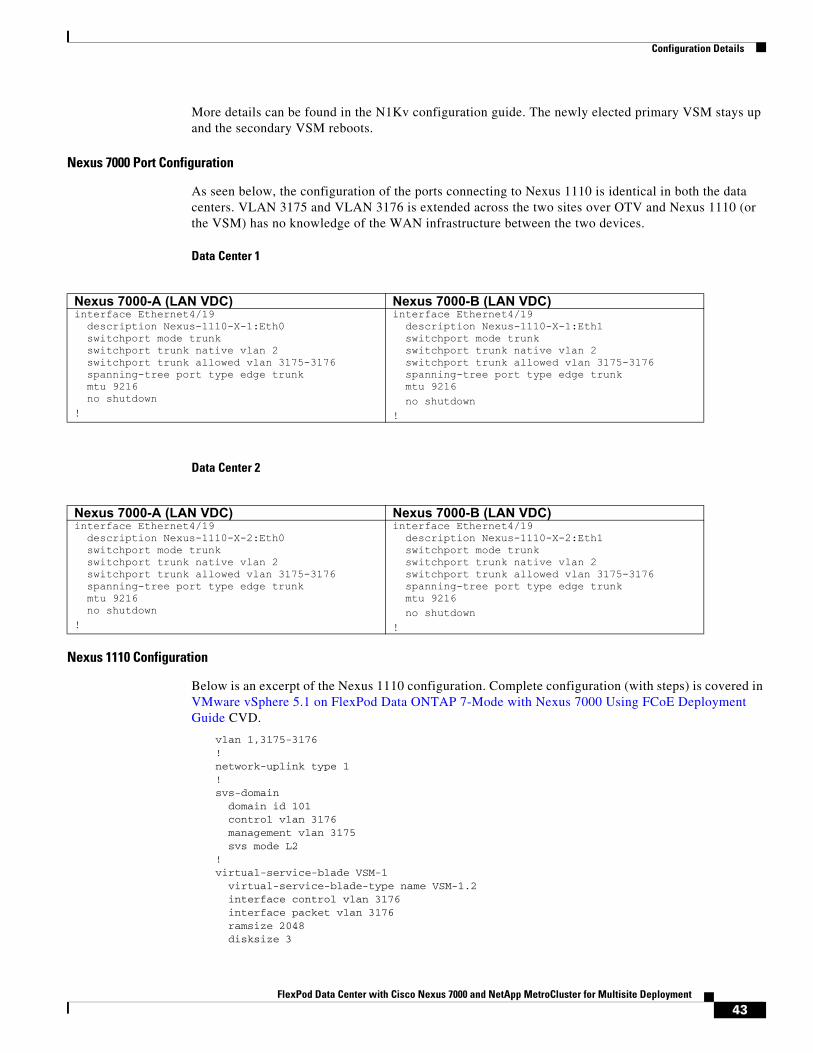
Configuration Details
More details can be found in the N1Kv configuration guide. The newly elected primary VSM stays up and the secondary VSM reboots.
Nexus 7000 Port Configuration
As seen below, the configuration of the ports connecting to Nexus 1110 is identical in both the data centers. VLAN 3175 and VLAN 3176 is extended across the two sites over OTV and Nexus 1110 (or the VSM) has no knowledge of the WAN infrastructure between the two devices.
Data Center 1
Data Center 2
Nexus 1110 Configuration
Below is an excerpt of the Nexus 1110 configuration. Complete configuration (with steps) is covered in VMware vSphere 5.1 on FlexPod Data ONTAP 7-Mode with Nexus 7000 Using FCoE Deployment Guide CVD.
vlan 1,3175-3176!network-uplink type 1!svs-domain domain id 101 control vlan 3176 management vlan 3175 svs mode L2!virtual-service-blade VSM-1 virtual-service-blade-type name VSM-1.2 interface control vlan 3176 interface packet vlan 3176 ramsize 2048 disksize 3
Nexus 7000-A (LAN VDC) Nexus 7000-B (LAN VDC)interface Ethernet4/19 description Nexus-1110-X-1:Eth0 switchport mode trunk switchport trunk native vlan 2 switchport trunk allowed vlan 3175-3176 spanning-tree port type edge trunk mtu 9216 no shutdown!
interface Ethernet4/19 description Nexus-1110-X-1:Eth1 switchport mode trunk switchport trunk native vlan 2 switchport trunk allowed vlan 3175-3176 spanning-tree port type edge trunk mtu 9216 no shutdown!
Nexus 7000-A (LAN VDC) Nexus 7000-B (LAN VDC)interface Ethernet4/19 description Nexus-1110-X-2:Eth0 switchport mode trunk switchport trunk native vlan 2 switchport trunk allowed vlan 3175-3176 spanning-tree port type edge trunk mtu 9216 no shutdown!
interface Ethernet4/19 description Nexus-1110-X-2:Eth1 switchport mode trunk switchport trunk native vlan 2 switchport trunk allowed vlan 3175-3176 spanning-tree port type edge trunk mtu 9216 no shutdown!
43FlexPod Data Center with Cisco Nexus 7000 and NetApp MetroCluster for Multisite Deployment
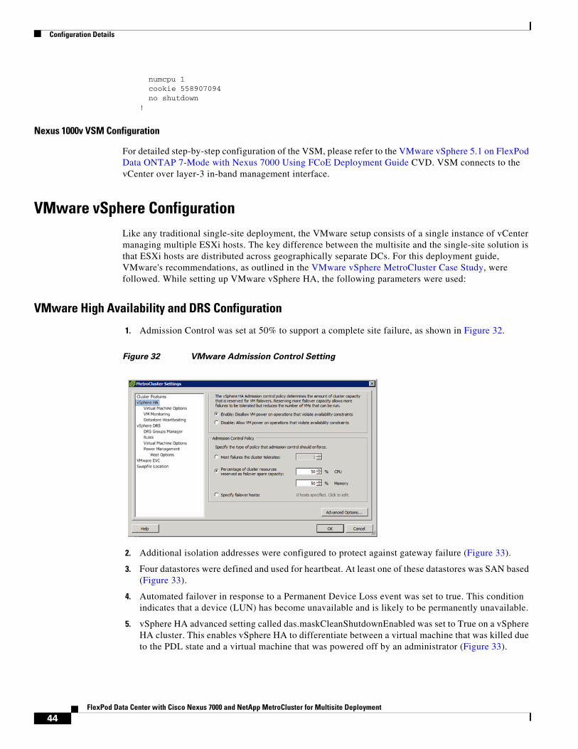
Configuration Details
numcpu 1 cookie 558907094 no shutdown!
Nexus 1000v VSM Configuration
For detailed step-by-step configuration of the VSM, please refer to the VMware vSphere 5.1 on FlexPod Data ONTAP 7-Mode with Nexus 7000 Using FCoE Deployment Guide CVD. VSM connects to the vCenter over layer-3 in-band management interface.
VMware vSphere ConfigurationLike any traditional single-site deployment, the VMware setup consists of a single instance of vCenter managing multiple ESXi hosts. The key difference between the multisite and the single-site solution is that ESXi hosts are distributed across geographically separate DCs. For this deployment guide, VMware's recommendations, as outlined in the VMware vSphere MetroCluster Case Study, were followed. While setting up VMware vSphere HA, the following parameters were used:
VMware High Availability and DRS Configuration
1. Admission Control was set at 50% to support a complete site failure, as shown in Figure 32.
Figure 32 VMware Admission Control Setting
2. Additional isolation addresses were configured to protect against gateway failure (Figure 33).
3. Four datastores were defined and used for heartbeat. At least one of these datastores was SAN based (Figure 33).
4. Automated failover in response to a Permanent Device Loss event was set to true. This condition indicates that a device (LUN) has become unavailable and is likely to be permanently unavailable.
5. vSphere HA advanced setting called das.maskCleanShutdownEnabled was set to True on a vSphere HA cluster. This enables vSphere HA to differentiate between a virtual machine that was killed due to the PDL state and a virtual machine that was powered off by an administrator (Figure 33).
44FlexPod Data Center with Cisco Nexus 7000 and NetApp MetroCluster for Multisite Deployment
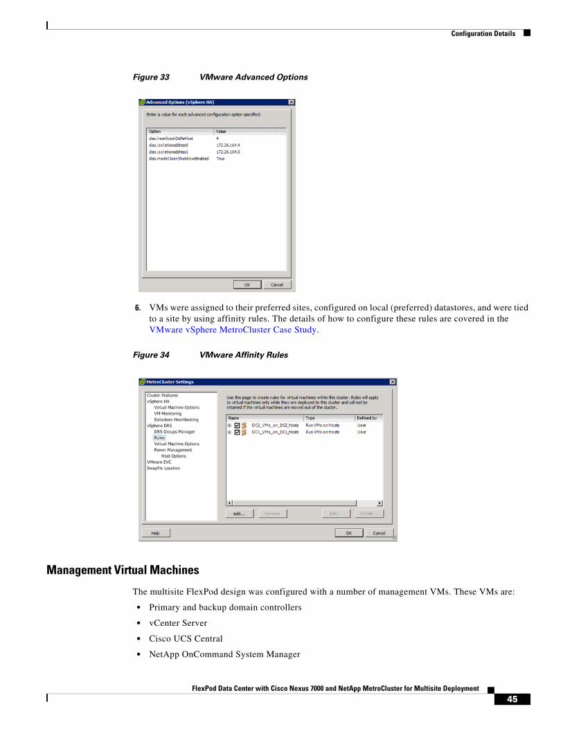
Configuration Details
Figure 33 VMware Advanced Options
6. VMs were assigned to their preferred sites, configured on local (preferred) datastores, and were tied to a site by using affinity rules. The details of how to configure these rules are covered in the VMware vSphere MetroCluster Case Study.
Figure 34 VMware Affinity Rules
Management Virtual Machines
The multisite FlexPod design was configured with a number of management VMs. These VMs are:
• Primary and backup domain controllers
• vCenter Server
• Cisco UCS Central
• NetApp OnCommand System Manager
45FlexPod Data Center with Cisco Nexus 7000 and NetApp MetroCluster for Multisite Deployment
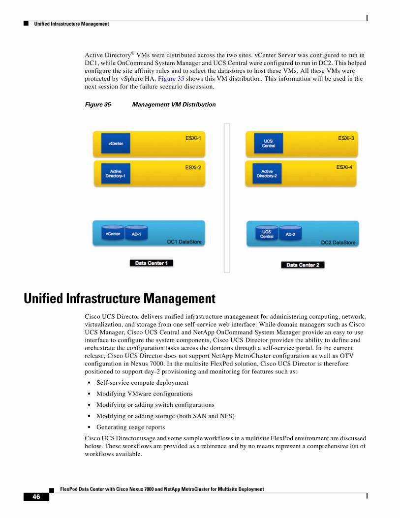
Unified Infrastructure Management
Active Directory® VMs were distributed across the two sites. vCenter Server was configured to run in DC1, while OnCommand System Manager and UCS Central were configured to run in DC2. This helped configure the site affinity rules and to select the datastores to host these VMs. All these VMs were protected by vSphere HA. Figure 35 shows this VM distribution. This information will be used in the next session for the failure scenario discussion.
Figure 35 Management VM Distribution
Unified Infrastructure ManagementCisco UCS Director delivers unified infrastructure management for administering computing, network, virtualization, and storage from one self-service web interface. While domain managers such as Cisco UCS Manager, Cisco UCS Central and NetApp OnCommand System Manager provide an easy to use interface to configure the system components, Cisco UCS Director provides the ability to define and orchestrate the configuration tasks across the domains through a self-service portal. In the current release, Cisco UCS Director does not support NetApp MetroCluster configuration as well as OTV configuration in Nexus 7000. In the multisite FlexPod solution, Cisco UCS Director is therefore positioned to support day-2 provisioning and monitoring for features such as:
• Self-service compute deployment
• Modifying VMware configurations
• Modifying or adding switch configurations
• Modifying or adding storage (both SAN and NFS)
• Generating usage reports
Cisco UCS Director usage and some sample workflows in a multisite FlexPod environment are discussed below. These workflows are provided as a reference and by no means represent a comprehensive list of workflows available.
46FlexPod Data Center with Cisco Nexus 7000 and NetApp MetroCluster for Multisite Deployment
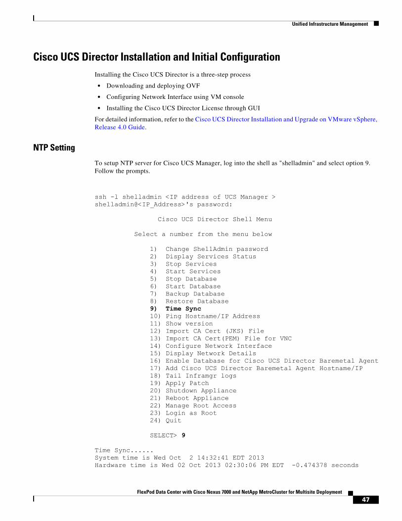
Unified Infrastructure Management
Cisco UCS Director Installation and Initial ConfigurationInstalling the Cisco UCS Director is a three-step process
• Downloading and deploying OVF
• Configuring Network Interface using VM console
• Installing the Cisco UCS Director License through GUI
For detailed information, refer to the Cisco UCS Director Installation and Upgrade on VMware vSphere, Release 4.0 Guide.
NTP Setting
To setup NTP server for Cisco UCS Manager, log into the shell as "shelladmin" and select option 9. Follow the prompts.
ssh -l shelladmin <IP address of UCS Manager >shelladmin@<IP_Address>'s password:
Cisco UCS Director Shell Menu
Select a number from the menu below
1) Change ShellAdmin password 2) Display Services Status 3) Stop Services 4) Start Services 5) Stop Database 6) Start Database 7) Backup Database 8) Restore Database 9) Time Sync 10) Ping Hostname/IP Address 11) Show version 12) Import CA Cert (JKS) File 13) Import CA Cert(PEM) File for VNC 14) Configure Network Interface 15) Display Network Details 16) Enable Database for Cisco UCS Director Baremetal Agent 17) Add Cisco UCS Director Baremetal Agent Hostname/IP 18) Tail Inframgr logs 19) Apply Patch 20) Shutdown Appliance 21) Reboot Appliance 22) Manage Root Access 23) Login as Root 24) Quit
SELECT> 9
Time Sync......System time is Wed Oct 2 14:32:41 EDT 2013Hardware time is Wed 02 Oct 2013 02:30:06 PM EDT -0.474378 seconds
47FlexPod Data Center with Cisco Nexus 7000 and NetApp MetroCluster for Multisite Deployment
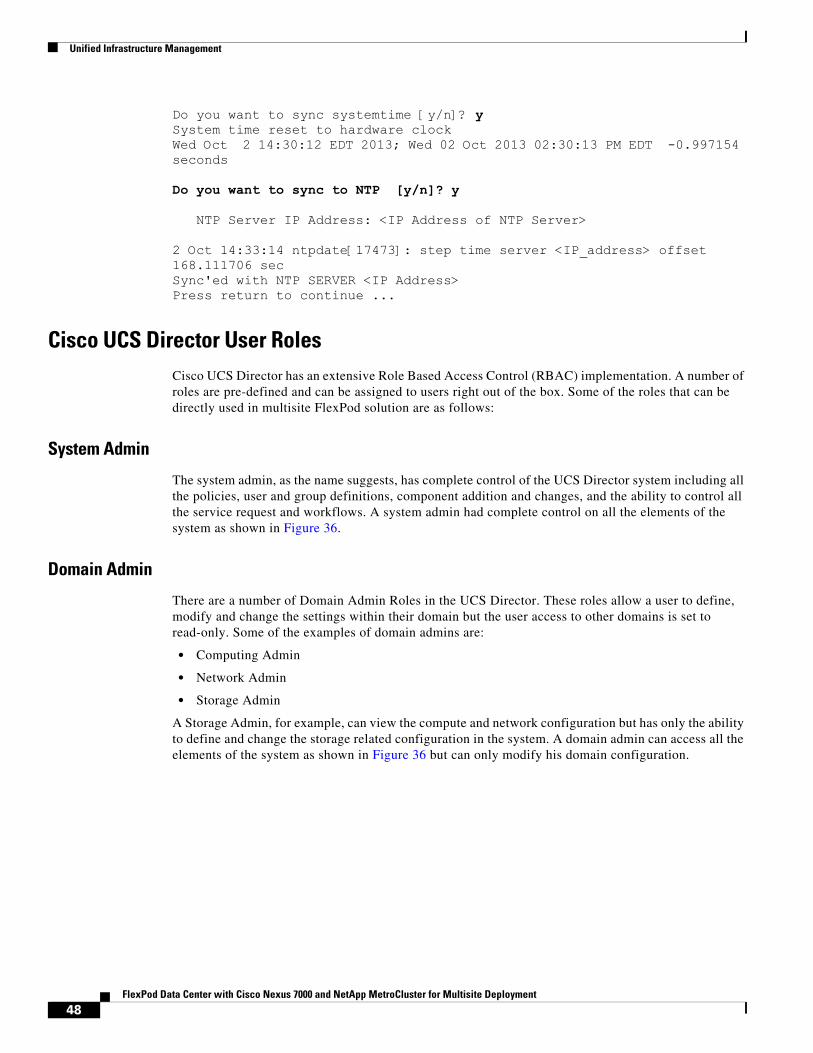
Unified Infrastructure Management
Do you want to sync systemtime [y/n]? ySystem time reset to hardware clockWed Oct 2 14:30:12 EDT 2013; Wed 02 Oct 2013 02:30:13 PM EDT -0.997154 seconds
Do you want to sync to NTP [y/n]? y
NTP Server IP Address: <IP Address of NTP Server>
2 Oct 14:33:14 ntpdate[17473]: step time server <IP_address> offset 168.111706 secSync'ed with NTP SERVER <IP Address>Press return to continue ...
Cisco UCS Director User RolesCisco UCS Director has an extensive Role Based Access Control (RBAC) implementation. A number of roles are pre-defined and can be assigned to users right out of the box. Some of the roles that can be directly used in multisite FlexPod solution are as follows:
System Admin
The system admin, as the name suggests, has complete control of the UCS Director system including all the policies, user and group definitions, component addition and changes, and the ability to control all the service request and workflows. A system admin had complete control on all the elements of the system as shown in Figure 36.
Domain Admin
There are a number of Domain Admin Roles in the UCS Director. These roles allow a user to define, modify and change the settings within their domain but the user access to other domains is set to read-only. Some of the examples of domain admins are:
• Computing Admin
• Network Admin
• Storage Admin
A Storage Admin, for example, can view the compute and network configuration but has only the ability to define and change the storage related configuration in the system. A domain admin can access all the elements of the system as shown in Figure 36 but can only modify his domain configuration.
48FlexPod Data Center with Cisco Nexus 7000 and NetApp MetroCluster for Multisite Deployment
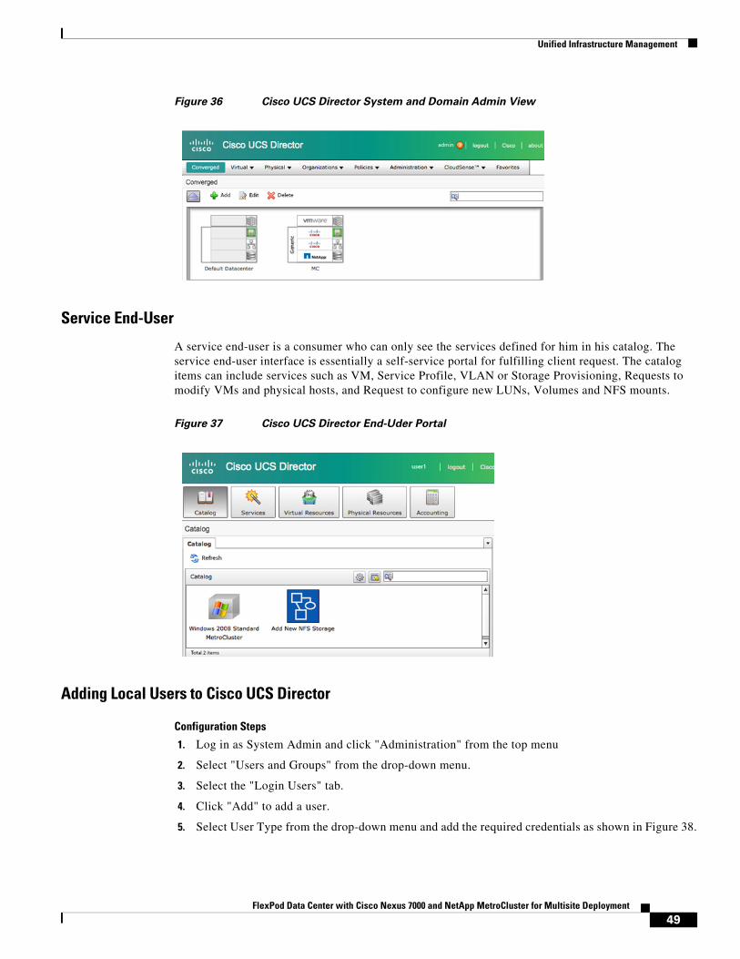
Unified Infrastructure Management
Figure 36 Cisco UCS Director System and Domain Admin View
Service End-User
A service end-user is a consumer who can only see the services defined for him in his catalog. The service end-user interface is essentially a self-service portal for fulfilling client request. The catalog items can include services such as VM, Service Profile, VLAN or Storage Provisioning, Requests to modify VMs and physical hosts, and Request to configure new LUNs, Volumes and NFS mounts.
Figure 37 Cisco UCS Director End-Uder Portal
Adding Local Users to Cisco UCS Director
Configuration Steps
1. Log in as System Admin and click "Administration" from the top menu
2. Select "Users and Groups" from the drop-down menu.
3. Select the "Login Users" tab.
4. Click "Add" to add a user.
5. Select User Type from the drop-down menu and add the required credentials as shown in Figure 38.
49FlexPod Data Center with Cisco Nexus 7000 and NetApp MetroCluster for Multisite Deployment
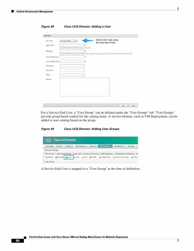
Unified Infrastructure Management
Figure 38 Cisco UCS Director: Adding a User
For a Service End-User, a "User Group" can be defined under the "User Groups" tab. "User Groups" provide group based control for the catalog items. A service element, such as VM Deployment, can be added to user catalog based on the group.
Figure 39 Cisco UCS Director: Adding User Groups
A Service End-User is mapped to a "User Group" at the time of definition.
50FlexPod Data Center with Cisco Nexus 7000 and NetApp MetroCluster for Multisite Deployment
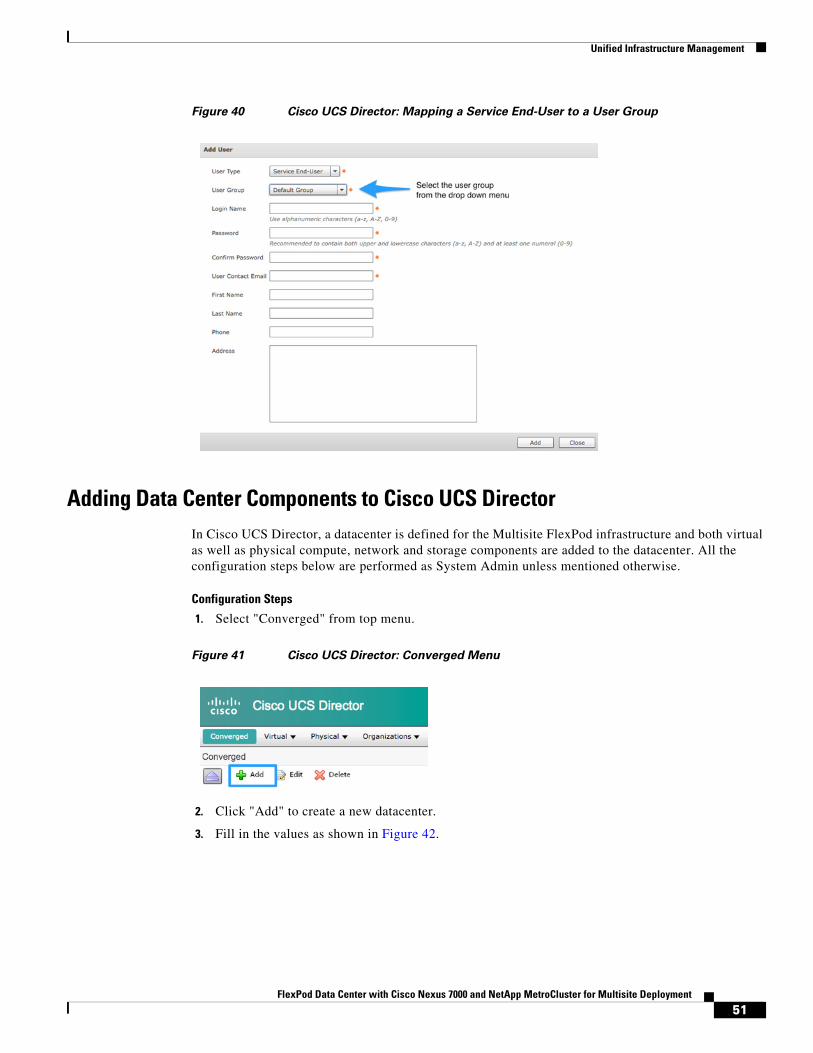
Unified Infrastructure Management
Figure 40 Cisco UCS Director: Mapping a Service End-User to a User Group
Adding Data Center Components to Cisco UCS DirectorIn Cisco UCS Director, a datacenter is defined for the Multisite FlexPod infrastructure and both virtual as well as physical compute, network and storage components are added to the datacenter. All the configuration steps below are performed as System Admin unless mentioned otherwise.
Configuration Steps
1. Select "Converged" from top menu.
Figure 41 Cisco UCS Director: Converged Menu
2. Click "Add" to create a new datacenter.
3. Fill in the values as shown in Figure 42.
51FlexPod Data Center with Cisco Nexus 7000 and NetApp MetroCluster for Multisite Deployment
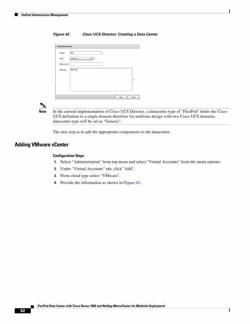
Unified Infrastructure Management
Figure 42 Cisco UCS Director: Creating a Data Center
Note In the current implementation of Cisco UCS Director, a datacenter type of "FlexPod" limits the Cisco UCS definition to a single domain therefore for multisite design with two Cisco UCS domains, datacenter type will be set as "Generic".
The nest step is to add the appropriate components to the datacenter.
Adding VMware vCenter
Configuration Steps
1. Select "Administration" from top menu and select "Virtual Accounts" from the menu options.
2. Under "Virtual Accounts" tab, click "Add".
3. From cloud type select "VMware".
4. Provide the information as shown in Figure 43.
52FlexPod Data Center with Cisco Nexus 7000 and NetApp MetroCluster for Multisite Deployment
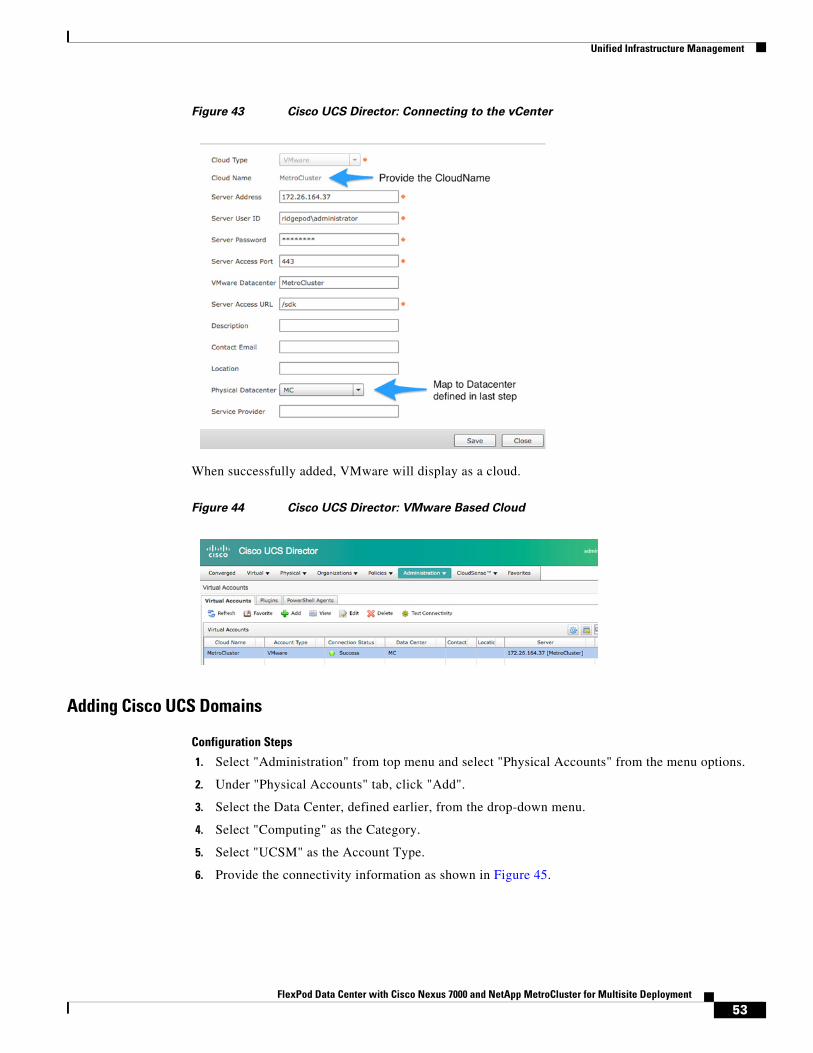
Unified Infrastructure Management
Figure 43 Cisco UCS Director: Connecting to the vCenter
When successfully added, VMware will display as a cloud.
Figure 44 Cisco UCS Director: VMware Based Cloud
Adding Cisco UCS Domains
Configuration Steps
1. Select "Administration" from top menu and select "Physical Accounts" from the menu options.
2. Under "Physical Accounts" tab, click "Add".
3. Select the Data Center, defined earlier, from the drop-down menu.
4. Select "Computing" as the Category.
5. Select "UCSM" as the Account Type.
6. Provide the connectivity information as shown in Figure 45.
53FlexPod Data Center with Cisco Nexus 7000 and NetApp MetroCluster for Multisite Deployment

Unified Infrastructure Management
Figure 45 Cisco UCS Director: Adding Cisco UCS Manager
7. Repeat steps 2-6 for the adding second Cisco UCS Domain.
Adding NetApp Controllers
Configuration Steps
1. Select "Administration" from top menu and select "Physical Accounts" from the menu options.
2. Under "Physical Accounts" tab, click "Add".
3. Select the Data Center, defined earlier, from the drop-down menu.
4. Select "Storage" as the Category.
5. Select "NetApp ONTAP" as Account Type.
6. Provide the connectivity information as shown in Figure 46.
54FlexPod Data Center with Cisco Nexus 7000 and NetApp MetroCluster for Multisite Deployment
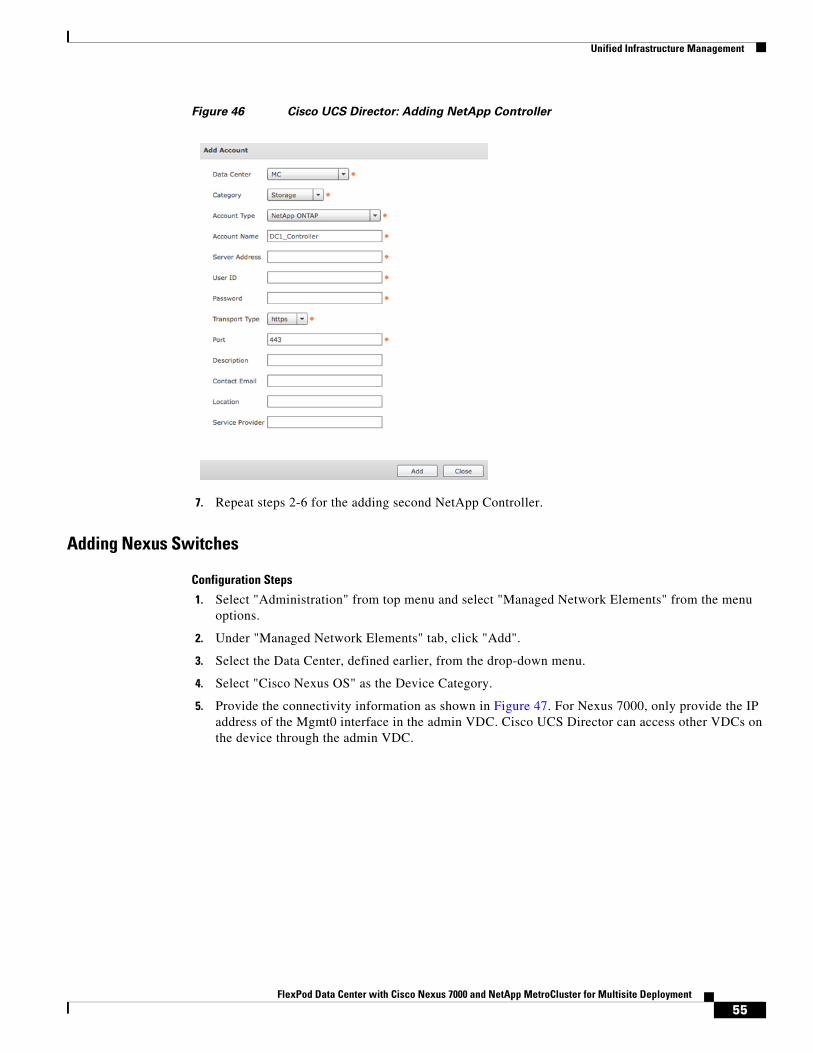
Unified Infrastructure Management
Figure 46 Cisco UCS Director: Adding NetApp Controller
7. Repeat steps 2-6 for the adding second NetApp Controller.
Adding Nexus Switches
Configuration Steps
1. Select "Administration" from top menu and select "Managed Network Elements" from the menu options.
2. Under "Managed Network Elements" tab, click "Add".
3. Select the Data Center, defined earlier, from the drop-down menu.
4. Select "Cisco Nexus OS" as the Device Category.
5. Provide the connectivity information as shown in Figure 47. For Nexus 7000, only provide the IP address of the Mgmt0 interface in the admin VDC. Cisco UCS Director can access other VDCs on the device through the admin VDC.
55FlexPod Data Center with Cisco Nexus 7000 and NetApp MetroCluster for Multisite Deployment
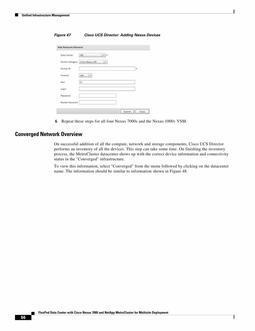
Unified Infrastructure Management
Figure 47 Cisco UCS Director: Adding Nexus Devices
6. Repeat these steps for all four Nexus 7000s and the Nexus 1000v VSM.
Converged Network Overview
On successful addition of all the compute, network and storage components, Cisco UCS Director performs an inventory of all the devices. This step can take some time. On finishing the inventory process, the MetroCluster datacenter shows up with the correct device information and connectivity status in the "Converged" infrastructure.
To view this information, select "Converged" from the menu followed by clicking on the datacenter name. The information should be similar to information shown in Figure 48.
56FlexPod Data Center with Cisco Nexus 7000 and NetApp MetroCluster for Multisite Deployment
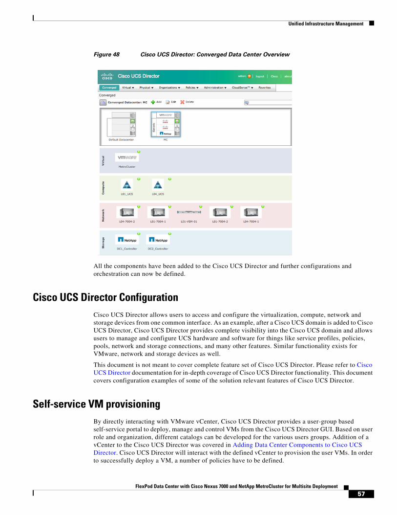
Unified Infrastructure Management
Figure 48 Cisco UCS Director: Converged Data Center Overview
All the components have been added to the Cisco UCS Director and further configurations and orchestration can now be defined.
Cisco UCS Director ConfigurationCisco UCS Director allows users to access and configure the virtualization, compute, network and storage devices from one common interface. As an example, after a Cisco UCS domain is added to Cisco UCS Director, Cisco UCS Director provides complete visibility into the Cisco UCS domain and allows users to manage and configure UCS hardware and software for things like service profiles, policies, pools, network and storage connections, and many other features. Similar functionality exists for VMware, network and storage devices as well.
This document is not meant to cover complete feature set of Cisco UCS Director. Please refer to Cisco UCS Director documentation for in-depth coverage of Cisco UCS Director functionality. This document covers configuration examples of some of the solution relevant features of Cisco UCS Director.
Self-service VM provisioningBy directly interacting with VMware vCenter, Cisco UCS Director provides a user-group based self-service portal to deploy, manage and control VMs from the Cisco UCS Director GUI. Based on user role and organization, different catalogs can be developed for the various users groups. Addition of a vCenter to the Cisco UCS Director was covered in Adding Data Center Components to Cisco UCS Director. Cisco UCS Director will interact with the defined vCenter to provision the user VMs. In order to successfully deploy a VM, a number of policies have to be defined.
57FlexPod Data Center with Cisco Nexus 7000 and NetApp MetroCluster for Multisite Deployment
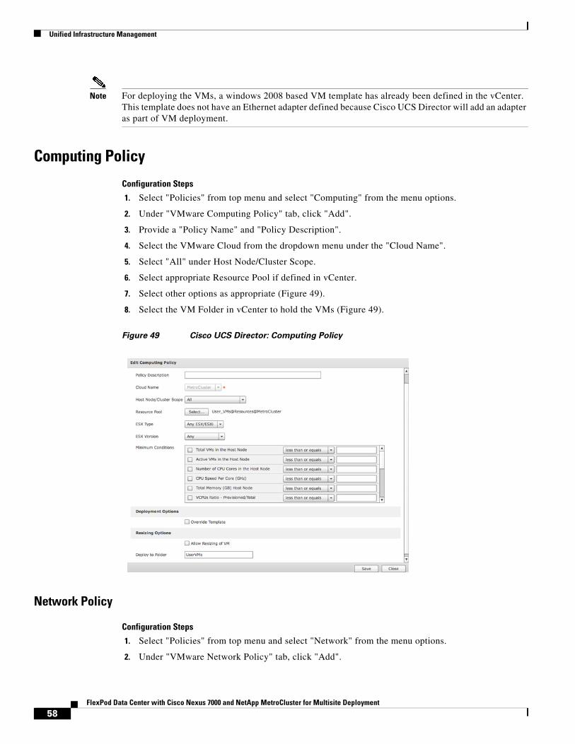
Unified Infrastructure Management
Note For deploying the VMs, a windows 2008 based VM template has already been defined in the vCenter. This template does not have an Ethernet adapter defined because Cisco UCS Director will add an adapter as part of VM deployment.
Computing Policy
Configuration Steps
1. Select "Policies" from top menu and select "Computing" from the menu options.
2. Under "VMware Computing Policy" tab, click "Add".
3. Provide a "Policy Name" and "Policy Description".
4. Select the VMware Cloud from the dropdown menu under the "Cloud Name".
5. Select "All" under Host Node/Cluster Scope.
6. Select appropriate Resource Pool if defined in vCenter.
7. Select other options as appropriate (Figure 49).
8. Select the VM Folder in vCenter to hold the VMs (Figure 49).
Figure 49 Cisco UCS Director: Computing Policy
Network Policy
Configuration Steps
1. Select "Policies" from top menu and select "Network" from the menu options.
2. Under "VMware Network Policy" tab, click "Add".
58FlexPod Data Center with Cisco Nexus 7000 and NetApp MetroCluster for Multisite Deployment
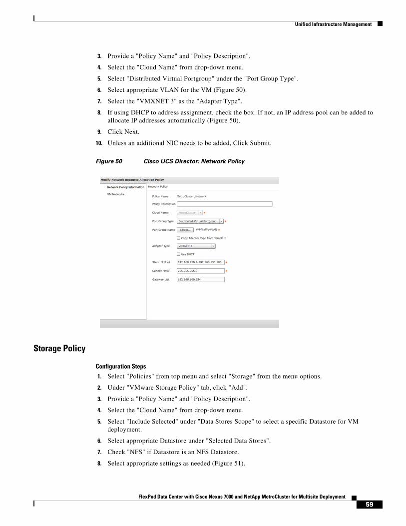
Unified Infrastructure Management
3. Provide a "Policy Name" and "Policy Description".
4. Select the "Cloud Name" from drop-down menu.
5. Select "Distributed Virtual Portgroup" under the "Port Group Type".
6. Select appropriate VLAN for the VM (Figure 50).
7. Select the "VMXNET 3" as the "Adapter Type".
8. If using DHCP to address assignment, check the box. If not, an IP address pool can be added to allocate IP addresses automatically (Figure 50).
9. Click Next.
10. Unless an additional NIC needs to be added, Click Submit.
Figure 50 Cisco UCS Director: Network Policy
Storage Policy
Configuration Steps
1. Select "Policies" from top menu and select "Storage" from the menu options.
2. Under "VMware Storage Policy" tab, click "Add".
3. Provide a "Policy Name" and "Policy Description".
4. Select the "Cloud Name" from drop-down menu.
5. Select "Include Selected" under "Data Stores Scope" to select a specific Datastore for VM deployment.
6. Select appropriate Datastore under "Selected Data Stores".
7. Check "NFS" if Datastore is an NFS Datastore.
8. Select appropriate settings as needed (Figure 51).
59FlexPod Data Center with Cisco Nexus 7000 and NetApp MetroCluster for Multisite Deployment
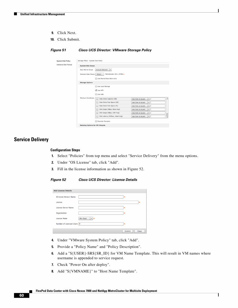
Unified Infrastructure Management
9. Click Next.
10. Click Submit.
Figure 51 Cisco UCS Director: VMware Storage Policy
Service Delivery
Configuration Steps
1. Select "Policies" from top menu and select "Service Delivery" from the menu options.
2. Under "OS License" tab, click "Add".
3. Fill in the license information as shown in Figure 52.
Figure 52 Cisco UCS Director: License Details
4. Under "VMware System Policy" tab, click "Add".
5. Provide a "Policy Name" and "Policy Description".
6. Add a "${USER}-SR${SR_ID} for VM Name Template. This will result in VM names where username is appended to service request.
7. Check "Power On after deploy".
8. Add "${VMNAME}" to "Host Name Template".
60FlexPod Data Center with Cisco Nexus 7000 and NetApp MetroCluster for Multisite Deployment
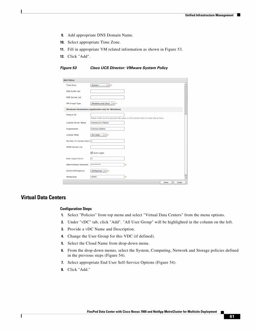
Unified Infrastructure Management
9. Add appropriate DNS Domain Name.
10. Select appropriate Time Zone.
11. Fill in appropriate VM related information as shown in Figure 53.
12. Click "Add".
Figure 53 Cisco UCS Director: VMware System Policy
Virtual Data Centers
Configuration Steps
1. Select "Policies" from top menu and select "Virtual Data Centers" from the menu options.
2. Under "vDC" tab, click "Add". "All User Group" will be highlighted in the column on the left.
3. Provide a vDC Name and Description.
4. Change the User Group for this VDC (if defined).
5. Select the Cloud Name from drop-down menu.
6. From the drop-down menus, select the System, Computing, Network and Storage policies defined in the previous steps (Figure 54).
7. Select appropriate End User Self-Service Options (Figure 54).
8. Click "Add."
61FlexPod Data Center with Cisco Nexus 7000 and NetApp MetroCluster for Multisite Deployment
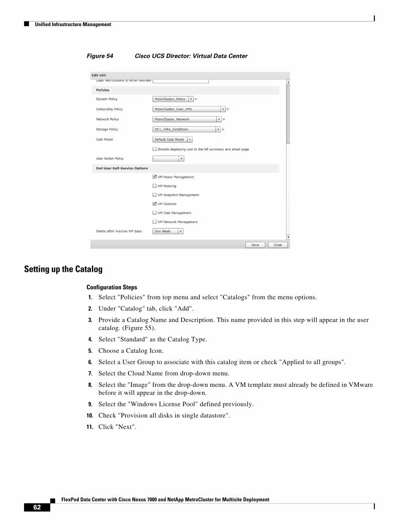
Unified Infrastructure Management
Figure 54 Cisco UCS Director: Virtual Data Center
Setting up the Catalog
Configuration Steps
1. Select "Policies" from top menu and select "Catalogs" from the menu options.
2. Under "Catalog" tab, click "Add".
3. Provide a Catalog Name and Description. This name provided in this step will appear in the user catalog. (Figure 55).
4. Select "Standard" as the Catalog Type.
5. Choose a Catalog Icon.
6. Select a User Group to associate with this catalog item or check "Applied to all groups".
7. Select the Cloud Name from drop-down menu.
8. Select the "Image" from the drop-down menu. A VM template must already be defined in VMware before it will appear in the drop-down.
9. Select the "Windows License Pool" defined previously.
10. Check "Provision all disks in single datastore".
11. Click "Next".
62FlexPod Data Center with Cisco Nexus 7000 and NetApp MetroCluster for Multisite Deployment
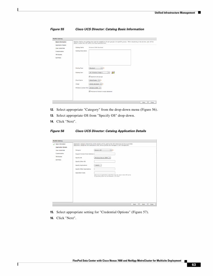
Unified Infrastructure Management
Figure 55 Cisco UCS Director: Catalog Basic Information
12. Select appropriate "Category" from the drop-down menu (Figure 56).
13. Select appropriate OS from "Specify OS" drop-down.
14. Click "Next".
Figure 56 Cisco UCS Director: Catalog Application Details
15. Select appropriate setting for "Credential Options" (Figure 57).
16. Click "Next".
63FlexPod Data Center with Cisco Nexus 7000 and NetApp MetroCluster for Multisite Deployment
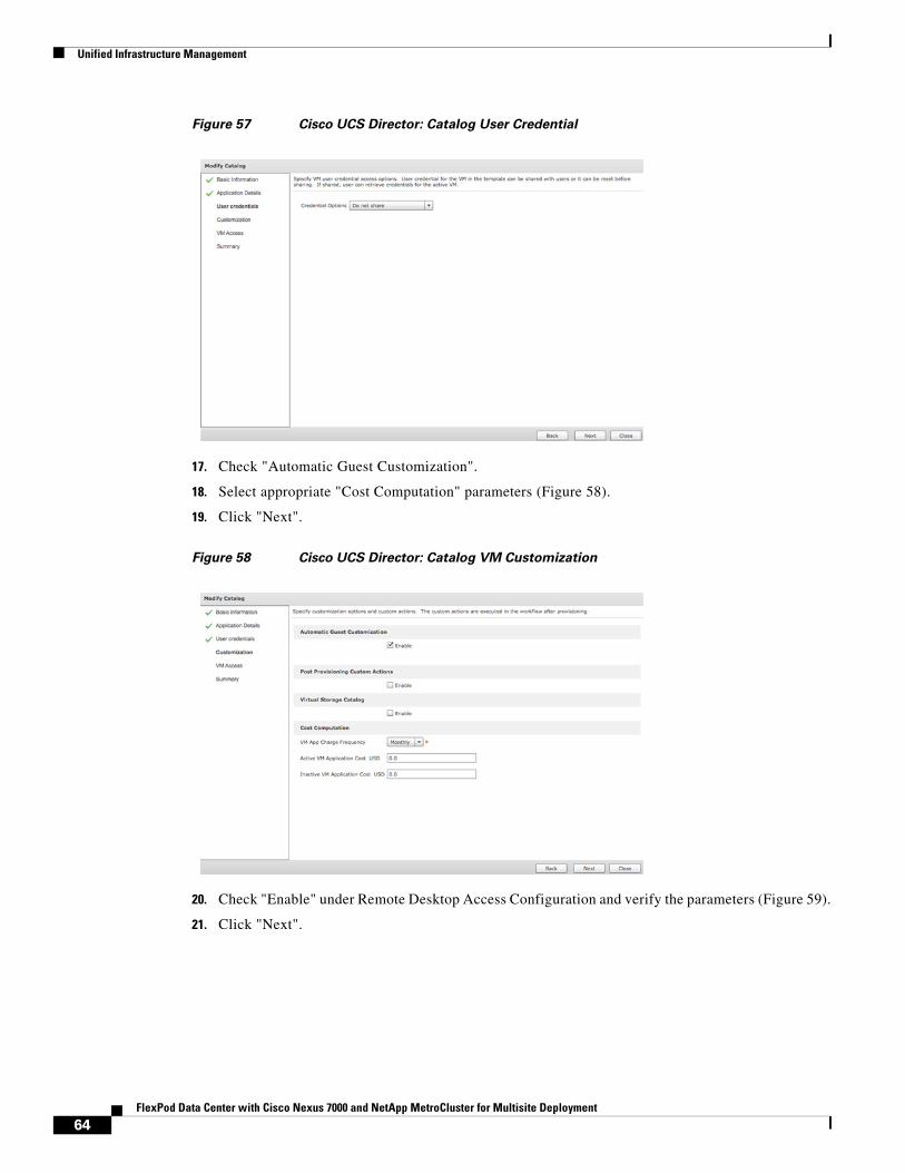
Unified Infrastructure Management
Figure 57 Cisco UCS Director: Catalog User Credential
17. Check "Automatic Guest Customization".
18. Select appropriate "Cost Computation" parameters (Figure 58).
19. Click "Next".
Figure 58 Cisco UCS Director: Catalog VM Customization
20. Check "Enable" under Remote Desktop Access Configuration and verify the parameters (Figure 59).
21. Click "Next".
64FlexPod Data Center with Cisco Nexus 7000 and NetApp MetroCluster for Multisite Deployment
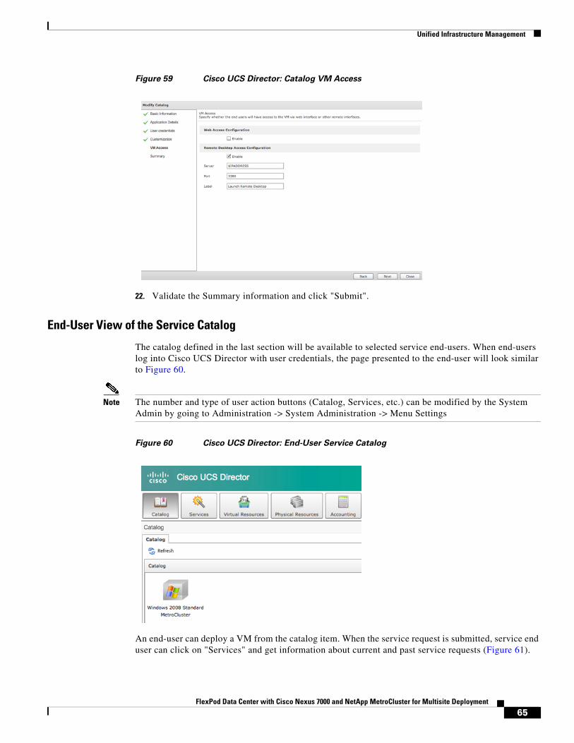
Unified Infrastructure Management
Figure 59 Cisco UCS Director: Catalog VM Access
22. Validate the Summary information and click "Submit".
End-User View of the Service Catalog
The catalog defined in the last section will be available to selected service end-users. When end-users log into Cisco UCS Director with user credentials, the page presented to the end-user will look similar to Figure 60.
Note The number and type of user action buttons (Catalog, Services, etc.) can be modified by the System Admin by going to Administration -> System Administration -> Menu Settings
Figure 60 Cisco UCS Director: End-User Service Catalog
An end-user can deploy a VM from the catalog item. When the service request is submitted, service end user can click on "Services" and get information about current and past service requests (Figure 61).
65FlexPod Data Center with Cisco Nexus 7000 and NetApp MetroCluster for Multisite Deployment
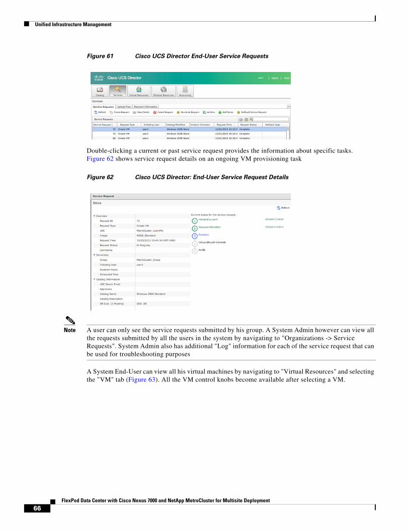
Unified Infrastructure Management
Figure 61 Cisco UCS Director End-User Service Requests
Double-clicking a current or past service request provides the information about specific tasks. Figure 62 shows service request details on an ongoing VM provisioning task
Figure 62 Cisco UCS Director: End-User Service Request Details
Note A user can only see the service requests submitted by his group. A System Admin however can view all the requests submitted by all the users in the system by navigating to "Organizations -> Service Requests". System Admin also has additional "Log" information for each of the service request that can be used for troubleshooting purposes
A System End-User can view all his virtual machines by navigating to "Virtual Resources" and selecting the "VM" tab (Figure 63). All the VM control knobs become available after selecting a VM.
66FlexPod Data Center with Cisco Nexus 7000 and NetApp MetroCluster for Multisite Deployment
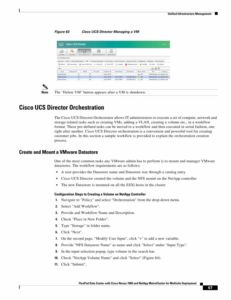
Unified Infrastructure Management
Figure 63 Cisco UCS Director Managing a VM
Note The "Delete VM" button appears after a VM is shutdown.
Cisco UCS Director OrchestrationThe Cisco UCS Director Orchestrator allows IT administrators to execute a set of compute, network and storage related tasks such as creating VMs, adding a VLAN, creating a volume etc., in a workflow format. These pre-defined tasks can be moved to a workflow and then executed in serial fashion, one right after another. Cisco UCS Director orchestration is a convenient and powerful tool for creating customer jobs. In this section a sample workflow is provided to explain the orchestration creation process.
Create and Mount a VMware Datastore
One of the most common tasks any VMware admin has to perform is to mount and manager VMware datastores. The workflow requirements are as follows:
• A user provides the Datastore name and Datastore size through a catalog entry
• Cisco UCS Director created the volume and the NFS mount on the NetApp controller
• The new Datastore is mounted on all the ESXi hosts in the cluster
Configuration Steps to Creating a Volume on NetApp Controller
1. Navigate to "Policy" and select "Orchestration" from the drop-down menu.
2. Select "Add Workflow".
3. Provide and Workflow Name and Description.
4. Check "Place in New Folder".
5. Type "Storage" in folder name.
6. Click "Next".
7. On the second page, "Modify User Input", click "+" to add a new variable.
8. Provide "NFS Datastore Name" as name and click "Select" under "Input Type".
9. In the input selection popup, type volume in the search bar.
10. Check "NetApp Volume Name" and click "Select" (Figure 64).
11. Click "Submit".
67FlexPod Data Center with Cisco Nexus 7000 and NetApp MetroCluster for Multisite Deployment
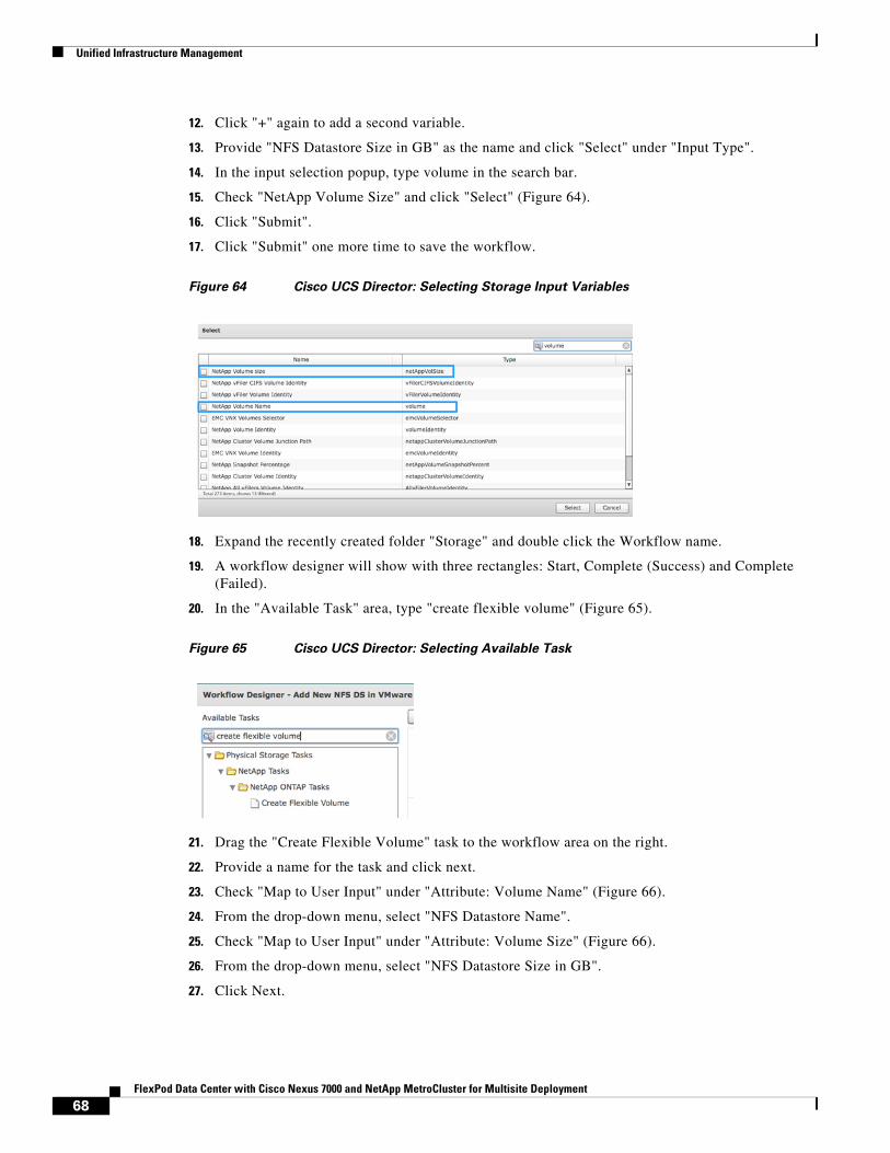
Unified Infrastructure Management
12. Click "+" again to add a second variable.
13. Provide "NFS Datastore Size in GB" as the name and click "Select" under "Input Type".
14. In the input selection popup, type volume in the search bar.
15. Check "NetApp Volume Size" and click "Select" (Figure 64).
16. Click "Submit".
17. Click "Submit" one more time to save the workflow.
Figure 64 Cisco UCS Director: Selecting Storage Input Variables
18. Expand the recently created folder "Storage" and double click the Workflow name.
19. A workflow designer will show with three rectangles: Start, Complete (Success) and Complete (Failed).
20. In the "Available Task" area, type "create flexible volume" (Figure 65).
Figure 65 Cisco UCS Director: Selecting Available Task
21. Drag the "Create Flexible Volume" task to the workflow area on the right.
22. Provide a name for the task and click next.
23. Check "Map to User Input" under "Attribute: Volume Name" (Figure 66).
24. From the drop-down menu, select "NFS Datastore Name".
25. Check "Map to User Input" under "Attribute: Volume Size" (Figure 66).
26. From the drop-down menu, select "NFS Datastore Size in GB".
27. Click Next.
68FlexPod Data Center with Cisco Nexus 7000 and NetApp MetroCluster for Multisite Deployment
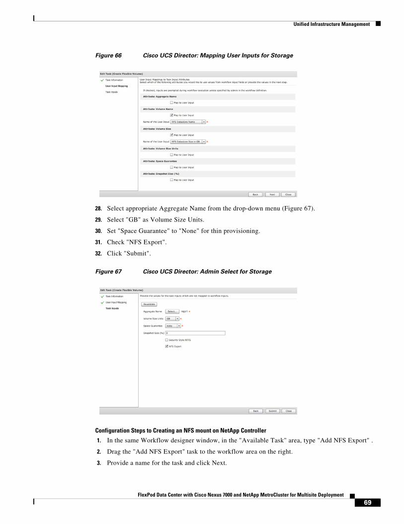
Unified Infrastructure Management
Figure 66 Cisco UCS Director: Mapping User Inputs for Storage
28. Select appropriate Aggregate Name from the drop-down menu (Figure 67).
29. Select "GB" as Volume Size Units.
30. Set "Space Guarantee" to "None" for thin provisioning.
31. Check "NFS Export".
32. Click "Submit".
Figure 67 Cisco UCS Director: Admin Select for Storage
Configuration Steps to Creating an NFS mount on NetApp Controller
1. In the same Workflow designer window, in the "Available Task" area, type "Add NFS Export" .
2. Drag the "Add NFS Export" task to the workflow area on the right.
3. Provide a name for the task and click Next.
69FlexPod Data Center with Cisco Nexus 7000 and NetApp MetroCluster for Multisite Deployment
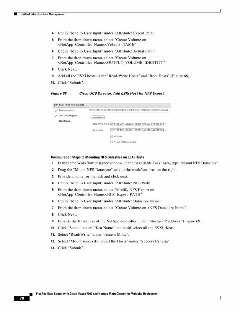
Unified Infrastructure Management
4. Check "Map to User Input" under "Attribute: Export Path".
5. From the drop-down menu, select "Create Volume on <NetApp_Controller_Name>.Volume_NAME"
6. Check "Map to User Input" under "Attribute: Actual Path".
7. From the drop-down menu, select "Create Volume on <NetApp_Controller_Name>.OUTPUT_VOLUME_IDENTITY"
8. Click Next.
9. Add all the ESXi hosts under "Read-Write Hosts" and "Root Hosts" (Figure 68).
10. Click "Submit".
Figure 68 Cisco UCS Director: Add ESXi Host for NFS Export
Configuration Steps to Mounting NFS Datastore on ESXi Hosts
1. In the same Workflow designer window, in the "Available Task" area, type "Mount NFS Datastore".
2. Drag the "Mount NFS Datastore" task to the workflow area on the right.
3. Provide a name for the task and click next.
4. Check "Map to User Input" under "Attribute: NFS Path".
5. From the drop-down menu, select "Modify NFS Export on <NetApp_Controller_Name>.NFS_Export_PATH"
6. Check "Map to User Input" under "Attribute: Datastore Name".
7. From the drop-down menu, select "Create Volume on <NFS Datastore Name".
8. Click Next.
9. Provide the IP address of the NetApp controller under "Storage IP address" (Figure 69).
10. Click "Select" under "Host Name" and multi-select all the ESXi Hosts.
11. Select "Read/Write" under "Access Mode".
12. Select "Mount successful on all the Hosts" under "Success Criteria".
13. Click "Submit".
70FlexPod Data Center with Cisco Nexus 7000 and NetApp MetroCluster for Multisite Deployment
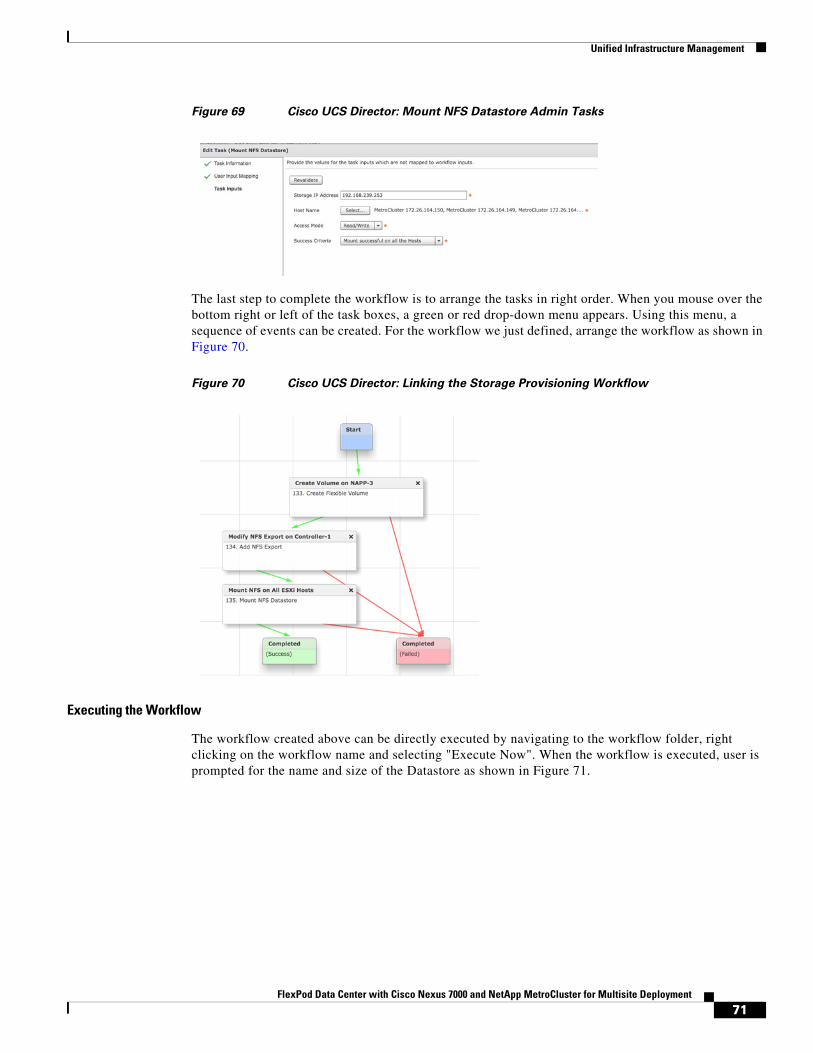
Unified Infrastructure Management
Figure 69 Cisco UCS Director: Mount NFS Datastore Admin Tasks
The last step to complete the workflow is to arrange the tasks in right order. When you mouse over the bottom right or left of the task boxes, a green or red drop-down menu appears. Using this menu, a sequence of events can be created. For the workflow we just defined, arrange the workflow as shown in Figure 70.
Figure 70 Cisco UCS Director: Linking the Storage Provisioning Workflow
Executing the Workflow
The workflow created above can be directly executed by navigating to the workflow folder, right clicking on the workflow name and selecting "Execute Now". When the workflow is executed, user is prompted for the name and size of the Datastore as shown in Figure 71.
71FlexPod Data Center with Cisco Nexus 7000 and NetApp MetroCluster for Multisite Deployment
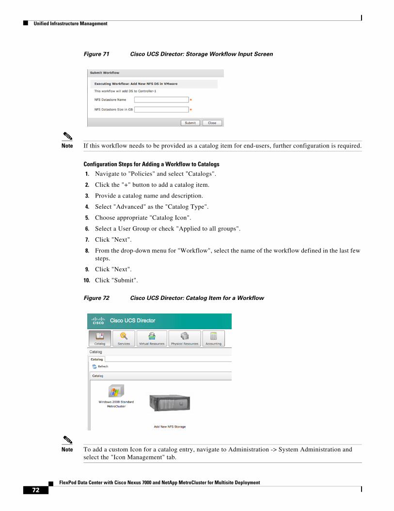
Unified Infrastructure Management
Figure 71 Cisco UCS Director: Storage Workflow Input Screen
Note If this workflow needs to be provided as a catalog item for end-users, further configuration is required.
Configuration Steps for Adding a Workflow to Catalogs
1. Navigate to "Policies" and select "Catalogs".
2. Click the "+" button to add a catalog item.
3. Provide a catalog name and description.
4. Select "Advanced" as the "Catalog Type".
5. Choose appropriate "Catalog Icon".
6. Select a User Group or check "Applied to all groups".
7. Click "Next".
8. From the drop-down menu for "Workflow", select the name of the workflow defined in the last few steps.
9. Click "Next".
10. Click "Submit".
Figure 72 Cisco UCS Director: Catalog Item for a Workflow
Note To add a custom Icon for a catalog entry, navigate to Administration -> System Administration and select the "Icon Management" tab.
72FlexPod Data Center with Cisco Nexus 7000 and NetApp MetroCluster for Multisite Deployment
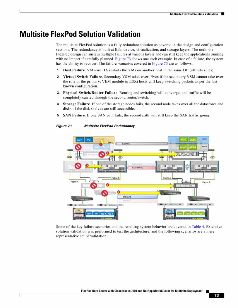
Multisite FlexPod Solution Validation
Multisite FlexPod Solution Validation The multisite FlexPod solution is a fully redundant solution as covered in the design and configuration sections. The redundancy is built at link, device, virtualization, and storage layers. The multisite FlexPod design can sustain multiple failures at various layers and can still keep the applications running with no impact if carefully planned. Figure 73 shows one such example. In case of a failure, the system has the ability to recover. The failure scenarios covered in Figure 73 are as follows:
1. Host Failure. VMware HA restarts the VMs on another host in the same DC (affinity rules).
2. Virtual Switch Failure. Secondary VSM takes over. Even if the secondary VSM cannot take over the role of the primary, VEM module in ESXi hosts will keep switching packets as per the last known configuration.
3. Physical Switch/Router Failure. Routing and switching will converge, and traffic will be completely carried through the second router/switch.
4. Storage Failure. If one of the storage nodes fails, the second node takes over all the datastores and disks, if the disk shelves are still accessible.
5. SAN Failure. If one SAN path fails, the second path will still keep the SAN traffic going.
Figure 73 Multisite FlexPod Redundancy
Some of the key failure scenarios and the resulting system behavior are covered in Table 4. Extensive solution validation was performed to test the architecture, and the following scenarios are a mere representative set of validation.
73FlexPod Data Center with Cisco Nexus 7000 and NetApp MetroCluster for Multisite Deployment
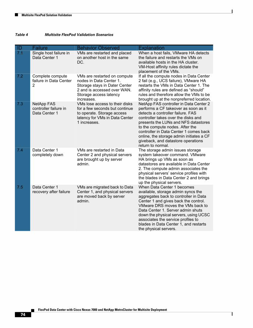
Multisite FlexPod Solution Validation
Table 4 Multisite FlexPod Validation Scenarios
ID Failure Behavior Observed Explanation7.1 Single host failure in
Data Center 1VMs are restarted and placed on another host in the same DC.
When a host fails, VMware HA detects the failure and restarts the VMs on available hosts in the HA cluster. VM-Host affinity rules dictate the placement of the VMs.
7.2 Complete compute failure in Data Center 2
VMs are restarted on compute nodes in Data Center 1. Storage stays in Dater Center 2 and is accessed over WAN. Storage access latency increases.
If all the compute nodes in Data Center 2 fail (e.g., UCS failure), VMware HA restarts the VMs in Data Center 1. The affinity rules are defined as “should” rules and therefore allow the VMs to be brought up at the nonpreferred location.
7.3 NetApp FAS controller failure in Data Center 1
VMs lose access to their disks for a few seconds but continue to operate. Storage access latency for VMs in Data Center 1 increases.
NetApp FAS controller in Data Center 2 performs a CF takeover as soon as it detects a controller failure. FAS controller takes over the disks and presents the LUNs and NFS datastores to the compute nodes. After the controller in Data Center 1 comes back online, the storage admin initiates a CF giveback, and datastore operations return to normal.
7.4 Data Center 1 completely down
VMs are restarted in Data Center 2 and physical servers are brought up by server admin.
The storage admin issues storage system takeover command. VMware HA brings up VMs as soon as datastores are available in Data Center 2. The compute admin associates the physical servers’ service profiles with the blades in Data Center 2 and brings up the physical servers.
7.5 Data Center 1 recovery after failure
VMs are migrated back to Data Center 1, and physical servers are moved back by server admin.
When Data Center 1 becomes available, storage admin syncs the aggregates back to controller in Data Center 1 and gives back the control. VMware DRS moves the VMs back to Data Center 1. Server admin shuts down the physical servers, using UCSC associates the service profiles to blades in Data Center 1, and restarts the physical servers.
74FlexPod Data Center with Cisco Nexus 7000 and NetApp MetroCluster for Multisite Deployment
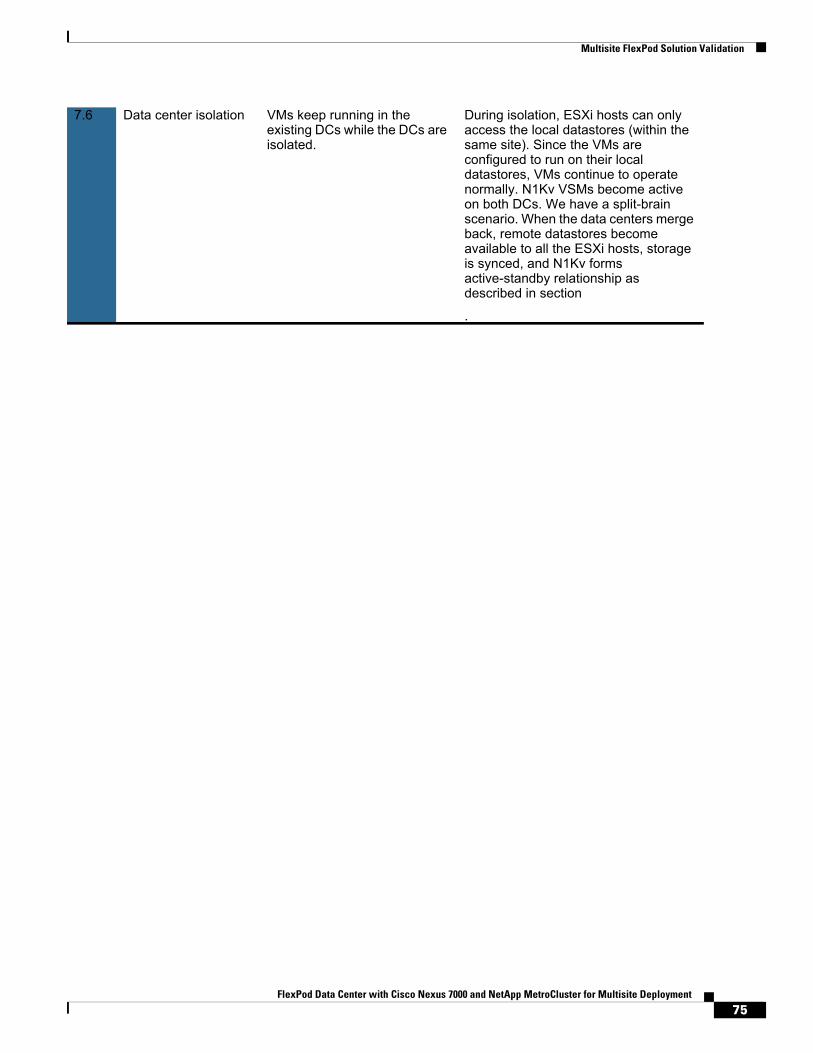
Multisite FlexPod Solution Validation
7.6 Data center isolation VMs keep running in the existing DCs while the DCs are isolated.
During isolation, ESXi hosts can only access the local datastores (within the same site). Since the VMs are configured to run on their local datastores, VMs continue to operate normally. N1Kv VSMs become active on both DCs. We have a split-brain scenario. When the data centers merge back, remote datastores become available to all the ESXi hosts, storage is synced, and N1Kv forms active-standby relationship as described in section
.
75FlexPod Data Center with Cisco Nexus 7000 and NetApp MetroCluster for Multisite Deployment
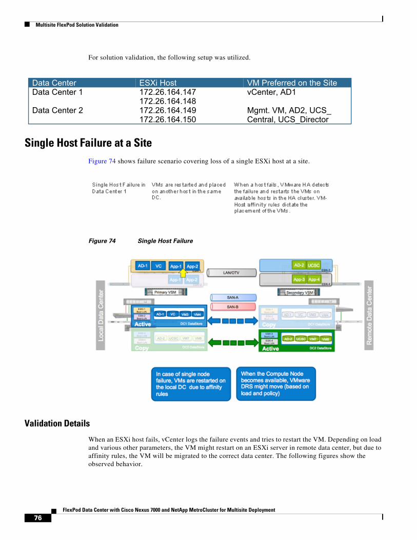
Multisite FlexPod Solution Validation
For solution validation, the following setup was utilized.
Single Host Failure at a SiteFigure 74 shows failure scenario covering loss of a single ESXi host at a site.
Figure 74 Single Host Failure
Validation Details
When an ESXi host fails, vCenter logs the failure events and tries to restart the VM. Depending on load and various other parameters, the VM might restart on an ESXi server in remote data center, but due to affinity rules, the VM will be migrated to the correct data center. The following figures show the observed behavior.
Data Center ESXi Host VM Preferred on the SiteData Center 1 172.26.164.147 vCenter, AD1
172.26.164.148Data Center 2 172.26.164.149 Mgmt. VM, AD2, UCS_
172.26.164.150 Central, UCS_Director
76FlexPod Data Center with Cisco Nexus 7000 and NetApp MetroCluster for Multisite Deployment
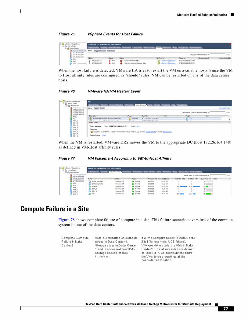
Multisite FlexPod Solution Validation
Figure 75 vSphere Events for Host Failure
When the host failure is detected, VMware HA tries to restart the VM on available hosts. Since the VM to Host affinity rules are configured as "should" rules, VM can be restarted on any of the data center hosts.
Figure 76 VMware HA VM Restart Event
When the VM is restarted, VMware DRS moves the VM to the appropriate DC (host 172.26.164.148) as defined in VM-Host affinity rules.
Figure 77 VM Placement According to VM-to-Host Affinity
Compute Failure in a SiteFigure 78 shows complete failure of compute in a site. This failure scenario covers loss of the compute system in one of the data centers.
77FlexPod Data Center with Cisco Nexus 7000 and NetApp MetroCluster for Multisite Deployment
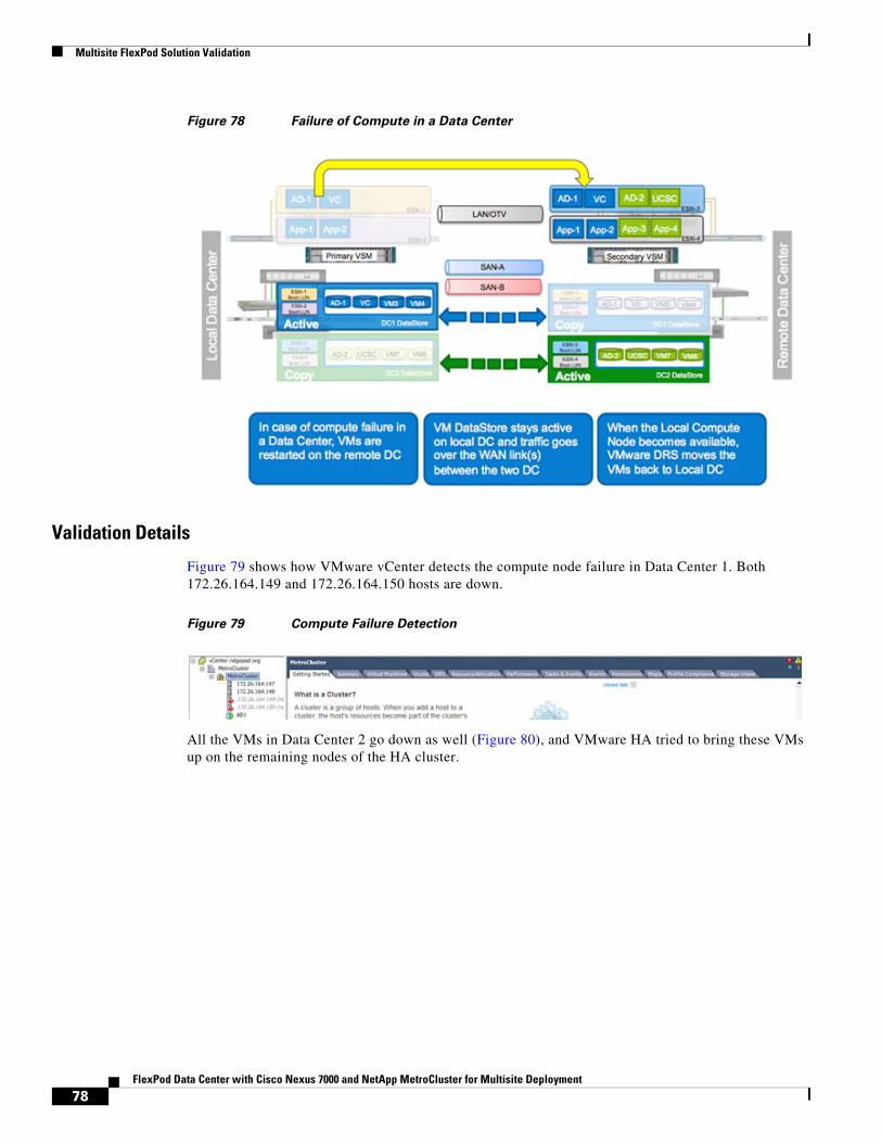
Multisite FlexPod Solution Validation
Figure 78 Failure of Compute in a Data Center
Validation Details
Figure 79 shows how VMware vCenter detects the compute node failure in Data Center 1. Both 172.26.164.149 and 172.26.164.150 hosts are down.
Figure 79 Compute Failure Detection
All the VMs in Data Center 2 go down as well (Figure 80), and VMware HA tried to bring these VMs up on the remaining nodes of the HA cluster.
78FlexPod Data Center with Cisco Nexus 7000 and NetApp MetroCluster for Multisite Deployment
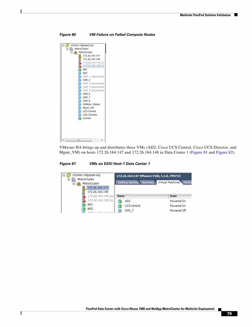
Multisite FlexPod Solution Validation
Figure 80 VM Failure on Failed Compute Nodes
VMware HA brings up and distributes these VMs (AD2, Cisco UCS Central, Cisco UCS Director, and Mgmt_VM) on hosts 172.26.164.147 and 172.26.164.148 in Data Center 1 (Figure 81 and Figure 82).
Figure 81 VMs on ESXi Host-1 Data Center 1
79FlexPod Data Center with Cisco Nexus 7000 and NetApp MetroCluster for Multisite Deployment
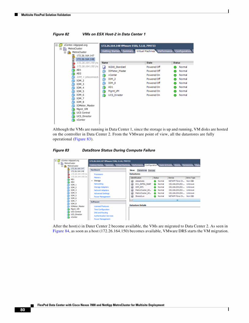
Multisite FlexPod Solution Validation
Figure 82 VMs on ESX Host-2 in Data Center 1
Although the VMs are running in Data Center 1, since the storage is up and running, VM disks are hosted on the controller in Data Center 2. From the VMware point of view, all the datastores are fully operational (Figure 83).
Figure 83 DataStore Status During Compute Failure
After the host(s) in Dater Center 2 become available, the VMs are migrated to Data Center 2. As seen in Figure 84, as soon as a host (172.26.164.150) becomes available, VMware DRS starts the VM migration.
80FlexPod Data Center with Cisco Nexus 7000 and NetApp MetroCluster for Multisite Deployment
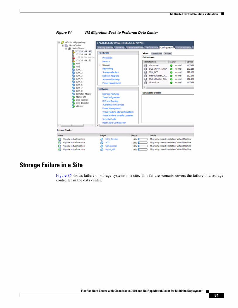
Multisite FlexPod Solution Validation
Figure 84 VM Migration Back to Preferred Data Center
Storage Failure in a SiteFigure 85 shows failure of storage systems in a site. This failure scenario covers the failure of a storage controller in the data center.
81FlexPod Data Center with Cisco Nexus 7000 and NetApp MetroCluster for Multisite Deployment
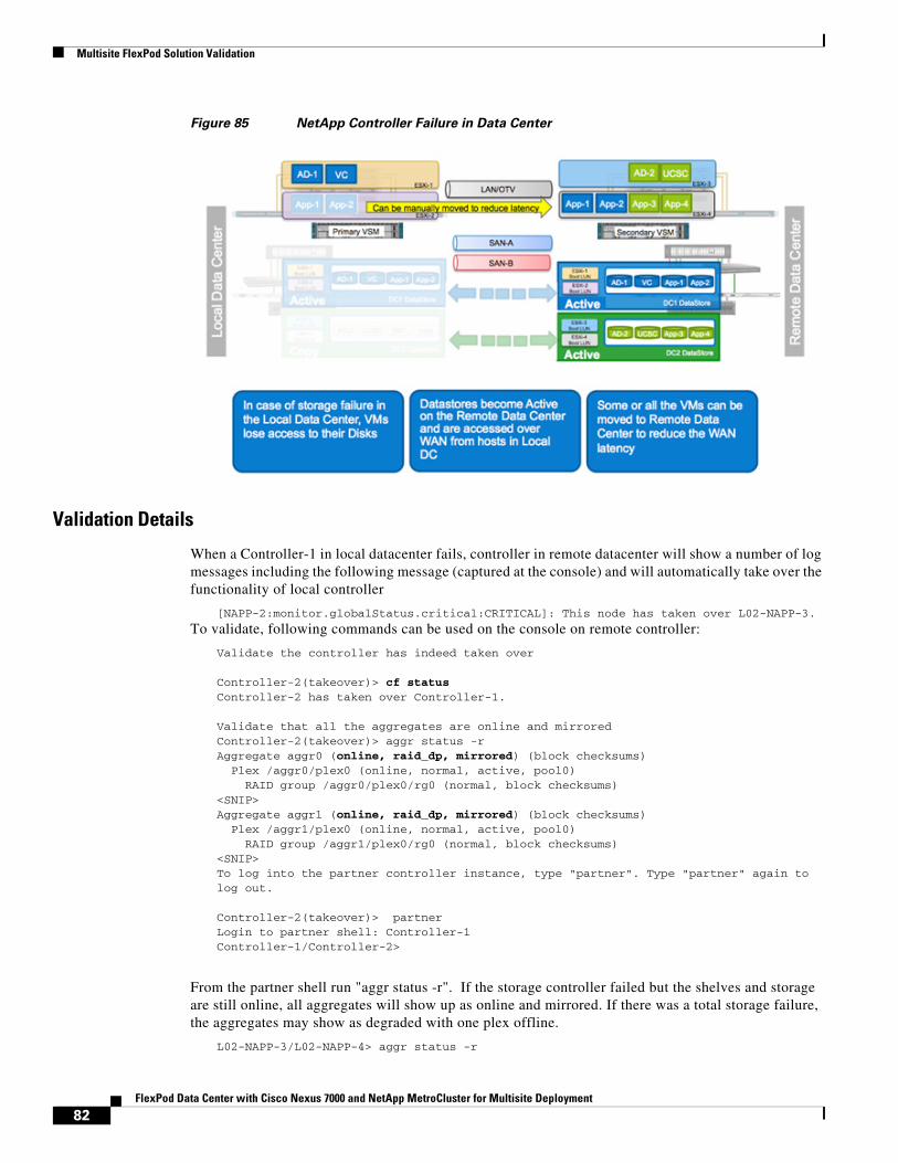
Multisite FlexPod Solution Validation
Figure 85 NetApp Controller Failure in Data Center
Validation Details
When a Controller-1 in local datacenter fails, controller in remote datacenter will show a number of log messages including the following message (captured at the console) and will automatically take over the functionality of local controller
[NAPP-2:monitor.globalStatus.critical:CRITICAL]: This node has taken over L02-NAPP-3.
To validate, following commands can be used on the console on remote controller:
Validate the controller has indeed taken over
Controller-2(takeover)> cf statusController-2 has taken over Controller-1.
Validate that all the aggregates are online and mirroredController-2(takeover)> aggr status -rAggregate aggr0 (online, raid_dp, mirrored) (block checksums) Plex /aggr0/plex0 (online, normal, active, pool0) RAID group /aggr0/plex0/rg0 (normal, block checksums)<SNIP>Aggregate aggr1 (online, raid_dp, mirrored) (block checksums) Plex /aggr1/plex0 (online, normal, active, pool0) RAID group /aggr1/plex0/rg0 (normal, block checksums)<SNIP>To log into the partner controller instance, type "partner". Type "partner" again to log out.
Controller-2(takeover)> partnerLogin to partner shell: Controller-1Controller-1/Controller-2>
From the partner shell run "aggr status -r". If the storage controller failed but the shelves and storage are still online, all aggregates will show up as online and mirrored. If there was a total storage failure, the aggregates may show as degraded with one plex offline.
L02-NAPP-3/L02-NAPP-4> aggr status -r
82FlexPod Data Center with Cisco Nexus 7000 and NetApp MetroCluster for Multisite Deployment
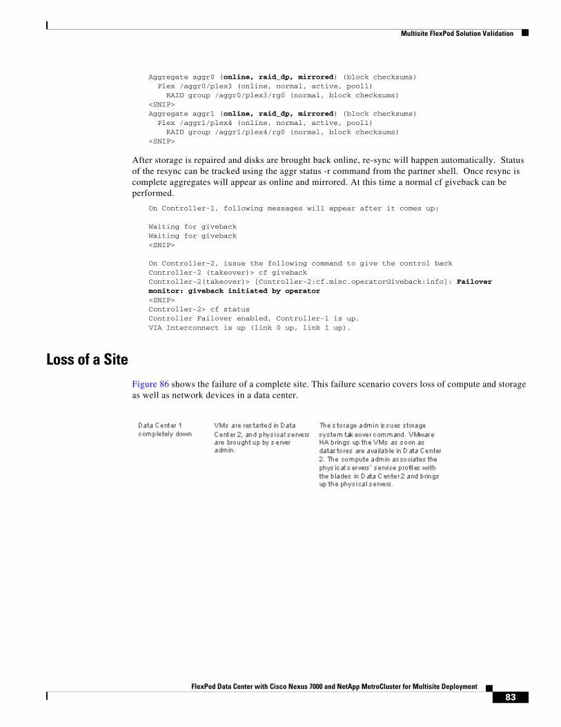
Multisite FlexPod Solution Validation
Aggregate aggr0 (online, raid_dp, mirrored) (block checksums) Plex /aggr0/plex3 (online, normal, active, pool1) RAID group /aggr0/plex3/rg0 (normal, block checksums)<SNIP>Aggregate aggr1 (online, raid_dp, mirrored) (block checksums) Plex /aggr1/plex4 (online, normal, active, pool1) RAID group /aggr1/plex4/rg0 (normal, block checksums)<SNIP>
After storage is repaired and disks are brought back online, re-sync will happen automatically. Status of the resync can be tracked using the aggr status -r command from the partner shell. Once resync is complete aggregates will appear as online and mirrored. At this time a normal cf giveback can be performed.
On Controller-1, following messages will appear after it comes up:
Waiting for givebackWaiting for giveback<SNIP>
On Controller-2, issue the following command to give the control backController-2 (takeover)> cf givebackController-2(takeover)> [Controller-2:cf.misc.operatorGiveback:info]: Failover monitor: giveback initiated by operator<SNIP>Controller-2> cf statusController Failover enabled, Controller-1 is up.VIA Interconnect is up (link 0 up, link 1 up).
Loss of a SiteFigure 86 shows the failure of a complete site. This failure scenario covers loss of compute and storage as well as network devices in a data center.
83FlexPod Data Center with Cisco Nexus 7000 and NetApp MetroCluster for Multisite Deployment
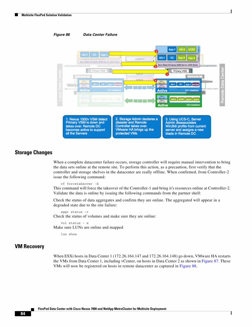
Multisite FlexPod Solution Validation
Figure 86 Data Center Failure
Storage Changes
When a complete datacenter failure occurs, storage controller will require manual intervention to bring the data sets online at the remote site. To perform this action, as a precaution, first verify that the controller and storage shelves in the datacenter are really offline. When confirmed, from Controller-2 issue the following command:
cf forcetakeover -d
This command will force the takeover of the Controller-1 and bring it's resources online at Controller-2. Validate the data is online by issuing the following commands from the partner shell:
Check the status of data aggregates and confirm they are online. The aggregated will appear in a degraded state due to the site failure:
aggr status -r
Check the status of volumes and make sure they are online:
vol status - e
Make sure LUNs are online and mapped
lun show
VM Recovery
When ESXi hosts in Data Center 1 (172.26.164.147 and 172.26.164.148) go down, VMware HA restarts the VMs from Data Center 1, including vCenter, on hosts in Data Center 2 as shown in Figure 87. These VMs will now be registered on hosts in remote datacenter as captured in Figure 88.
84FlexPod Data Center with Cisco Nexus 7000 and NetApp MetroCluster for Multisite Deployment
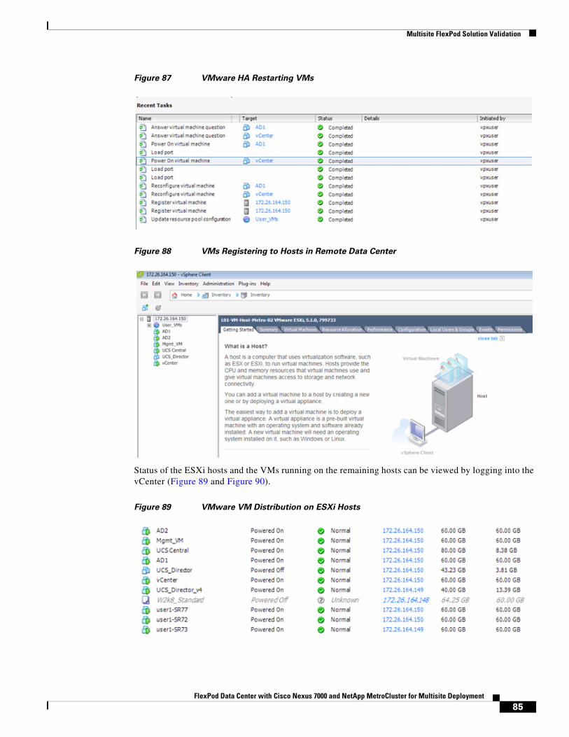
Multisite FlexPod Solution Validation
Figure 87 VMware HA Restarting VMs
Figure 88 VMs Registering to Hosts in Remote Data Center
Status of the ESXi hosts and the VMs running on the remaining hosts can be viewed by logging into the vCenter (Figure 89 and Figure 90).
Figure 89 VMware VM Distribution on ESXi Hosts
85FlexPod Data Center with Cisco Nexus 7000 and NetApp MetroCluster for Multisite Deployment
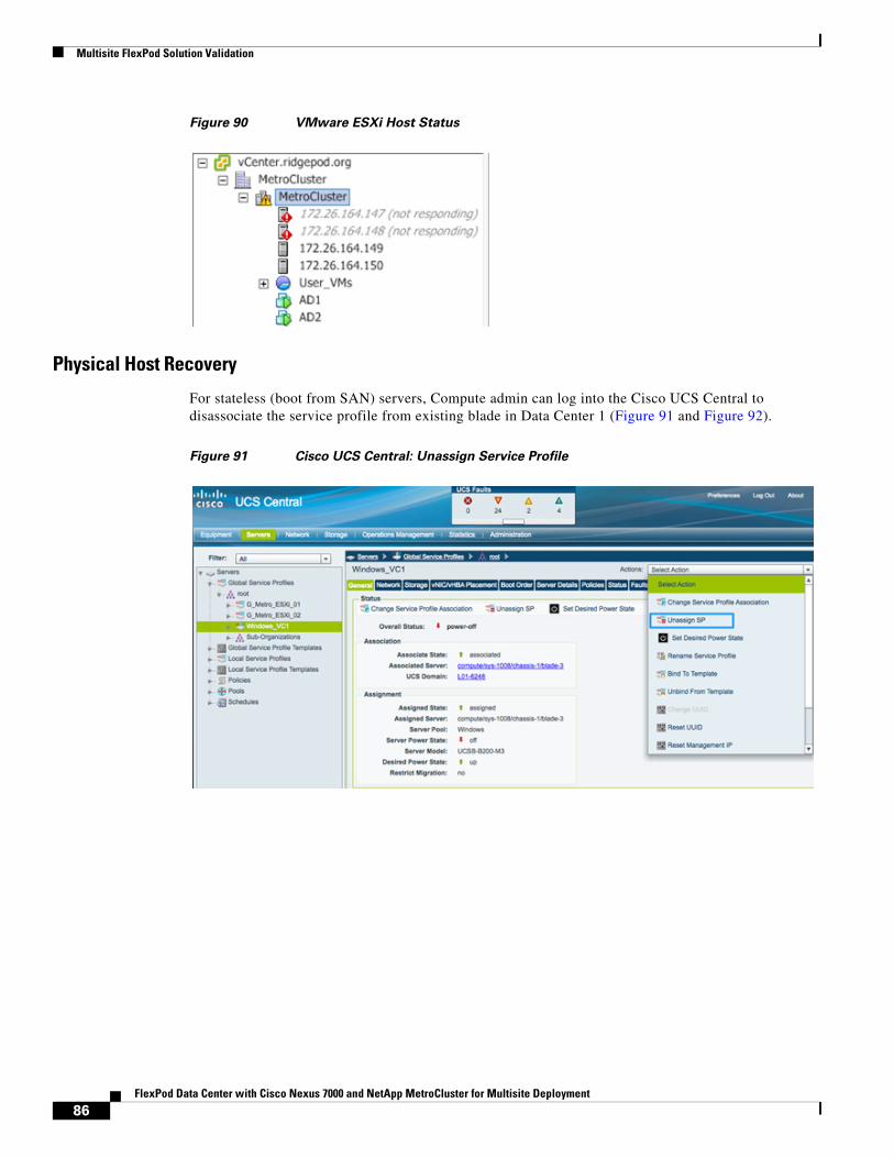
Multisite FlexPod Solution Validation
Figure 90 VMware ESXi Host Status
Physical Host Recovery
For stateless (boot from SAN) servers, Compute admin can log into the Cisco UCS Central to disassociate the service profile from existing blade in Data Center 1 (Figure 91 and Figure 92).
Figure 91 Cisco UCS Central: Unassign Service Profile
86FlexPod Data Center with Cisco Nexus 7000 and NetApp MetroCluster for Multisite Deployment
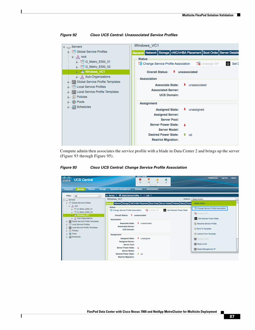
Multisite FlexPod Solution Validation
Figure 92 Cisco UCS Central: Unassociated Service Profiles
Compute admin then associates the service profile with a blade in Data Center 2 and brings up the server (Figure 93 through Figure 95).
Figure 93 Cisco UCS Central: Change Service Profile Association
87FlexPod Data Center with Cisco Nexus 7000 and NetApp MetroCluster for Multisite Deployment
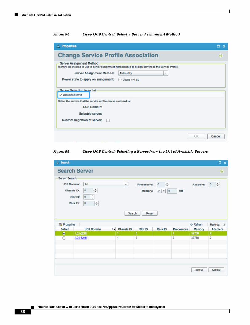
Multisite FlexPod Solution Validation
Figure 94 Cisco UCS Central: Select a Server Assignment Method
Figure 95 Cisco UCS Central: Selecting a Server from the List of Available Servers
88FlexPod Data Center with Cisco Nexus 7000 and NetApp MetroCluster for Multisite Deployment
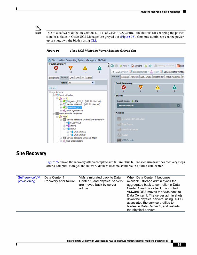
Multisite FlexPod Solution Validation
Note Due to a software defect in version 1.1(1a) of Cisco UCS Central, the buttons for changing the power state of a blade in Cisco UCS Manager are grayed out (Figure 96). Compute admin can change power up or shutdown the blades using CLI.
Figure 96 Cisco UCS Manager: Power Buttons Grayed Out
Site RecoveryFigure 97 shows the recovery after a complete site failure. This failure scenario describes recovery steps after a compute, storage, and network devices become available in a failed data center.
Self-service VM provisioning
Data Center 1 Recovery after failure
VMs a migrated back to Data Center 1, and physical servers are moved back by server admin.
When Data Center 1 becomes available, storage admin syncs the aggregates back to controller in Data Center 1 and gives back the control. VMware DRS moves the VMs back to Data Center 1. The server admin shuts down the physical servers, using UCSC associates the service profiles to blades in Data Center 1, and restarts the physical servers.
89FlexPod Data Center with Cisco Nexus 7000 and NetApp MetroCluster for Multisite Deployment
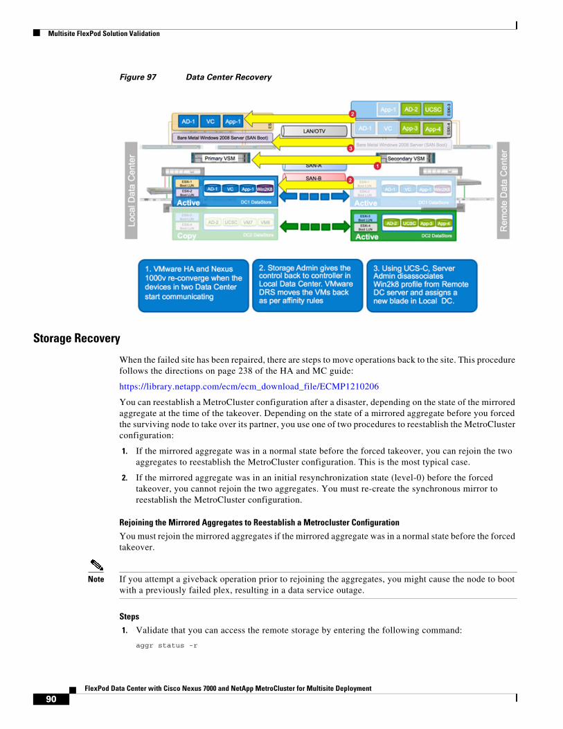
Multisite FlexPod Solution Validation
Figure 97 Data Center Recovery
Storage Recovery
When the failed site has been repaired, there are steps to move operations back to the site. This procedure follows the directions on page 238 of the HA and MC guide:
https://library.netapp.com/ecm/ecm_download_file/ECMP1210206
You can reestablish a MetroCluster configuration after a disaster, depending on the state of the mirrored aggregate at the time of the takeover. Depending on the state of a mirrored aggregate before you forced the surviving node to take over its partner, you use one of two procedures to reestablish the MetroCluster configuration:
1. If the mirrored aggregate was in a normal state before the forced takeover, you can rejoin the two aggregates to reestablish the MetroCluster configuration. This is the most typical case.
2. If the mirrored aggregate was in an initial resynchronization state (level-0) before the forced takeover, you cannot rejoin the two aggregates. You must re-create the synchronous mirror to reestablish the MetroCluster configuration.
Rejoining the Mirrored Aggregates to Reestablish a Metrocluster Configuration
You must rejoin the mirrored aggregates if the mirrored aggregate was in a normal state before the forced takeover.
Note If you attempt a giveback operation prior to rejoining the aggregates, you might cause the node to boot with a previously failed plex, resulting in a data service outage.
Steps
1. Validate that you can access the remote storage by entering the following command:
aggr status -r
90FlexPod Data Center with Cisco Nexus 7000 and NetApp MetroCluster for Multisite Deployment
Multisite FlexPod Solution Validation
2. Turn on power to the node at the disaster site. After the node at the disaster site boots, it displays the following message:
Waiting for Giveback...
3. Determine which aggregates are at the surviving site and which aggregates are at the disaster site by using the following command:
aggr status
4. Aggregates at the disaster site should show plexes that are in a failed state with an out-of-date status. Aggregates at the surviving site should show plexes as online. If aggregates at the disaster site are online, take them offline by entering the following command for each online aggregate:
aggr offline disaster_aggr disaster_aggris the name of the aggregate at the disaster site.
Note An error message appears if the aggregate is already offline.
5. Re-create the mirrored aggregates by entering the following command for each aggregate that was split:
aggr mirror aggr_name -v disaster_aggr aggr_name is the aggregate on the surviving site's node.disaster_aggr is the aggregate on the disaster site's node.
The aggr_name aggregate rejoins the disaster_aggr aggregate to reestablish the MetroCluster configuration.
6. Verify that the mirrored aggregates have been re-created by entering the following command:
aggr status -r
The giveback operation only succeeds if the aggregates have been rejoined.
7. Enter the following command at the partner node:
cf giveback
The node at the disaster site reboots and normal operation is resumed.
VM Migration
VM migration is automatically performed by VMware DRS affinity rules. When the ESXi hosts in Data Center 1 become available, VMs belonging to datacenter 1 are moved back to these hosts using vMotion
Physical Host Migration
Compute admin has to shutdown a server and follow the same procedure as mentioned in last failure scenario to manually associate the service profiles with blades in datacenter 1.
Data Center IsolationFigure 98 shows system availability after data center isolation. This failure scenario describes a case in which all the links (LAN and SAN) between the two data centers become unavailable.
91FlexPod Data Center with Cisco Nexus 7000 and NetApp MetroCluster for Multisite Deployment
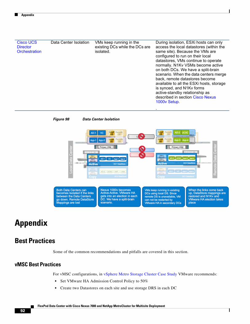
Appendix
Figure 98 Data Center Isolation
Appendix
Best PracticesSome of the common recommendations and pitfalls are covered in this section.
vMSC Best Practices
For vMSC configurations, in vSphere Metro Storage Cluster Case Study VMware recommends:
• Set VMware HA Admission Control Policy to 50%
• Create two Datastores on each site and use storage DRS in each DC
Cisco UCS Director Orchestration
Data Center Isolation VMs keep running in the existing DCs while the DCs are isolated.
During isolation, ESXi hosts can only access the local datastores (within the same site). Because the VMs are configured to run on their local datastores, VMs continue to operate normally. N1Kv VSMs become active on both DCs. We have a split-brain scenario. When the data centers merge back, remote datastores become available to all the ESXi hosts, storage is synced, and N1Kv forms active-standby relationship as described in section Cisco Nexus 1000v Setup.
.
92FlexPod Data Center with Cisco Nexus 7000 and NetApp MetroCluster for Multisite Deployment
Appendix
• Use at least four Datastores for heartbeat. To protect against IP-only network failure, for multisite FlexPod design at least one of these four datastores was SAN based shared LUN.
• Configure Additional Isolation Addresses to test IP connectivity
• Set das.maskCleanShutdownEnabled to True for VMware to distinguish clean-shutdown VMs from VM shutdown due to storage unavailability.
• Assign a primary site for VM operation and define appropriate VM-Host affinity
Infrastructure Best Practices
• OTV adds a 42 byte overhead to every packet. When setting the MTU sizes for VMkernel ports or for storage and compute nodes, this overhead should be taken into consideration
• At least two domain controllers should be setup for Active Directory. These domain controllers should be distributed across the two sites - one on each site. vCenter should be able to use either of these Domain Controllers for authentication
• When using both Cisco UCS Manager and UCS Central concurrently, unique names and values for global policies, templates and pool should be used. Adding a prefix before the name of a certain field such as "G_" is fairly common.
• Boot from SAN policies and zoning should include both local and remote NetApp controller WWPNs.
• Verify that cf.takeover.change_fsid option is set to "off" on the NetApp controller. In Data ONTAP 8.2, the change_fsid option is disabled (set to off) by default.
Existing Documents (References)• Cisco OTV
• Cisco Nexus 1kV
• Cisco UCS Central
• TR-3548 MetroCluster Best Practices
• MetroCluster FAQ
• VMSC White Paper
• VMSC KB Article
• VMware VMSC Tech Paper
93FlexPod Data Center with Cisco Nexus 7000 and NetApp MetroCluster for Multisite Deployment