FlexNET link Connecting The World. 2 FlexNET LINK FlexNET LINK Frequency Division Duplex (FDD) –...
18
FlexNET link FlexNET link Connecting The World
-
Upload
naomi-houston -
Category
Documents
-
view
234 -
download
0
Transcript of FlexNET link Connecting The World. 2 FlexNET LINK FlexNET LINK Frequency Division Duplex (FDD) –...

FlexNET linkFlexNET link
Connecting The World

2
FlexNET LINKFlexNET LINK
• Frequency Division Duplex (FDD) – AS.MAX– Communications in one direction are at a different frequency than in the other
direction, transmitting and receiving in both directions at the same time
• Can establish high speeds in both directions (usually equivalent speed)
• No substantial time delays (latency) for communication, as no information is buffered
• The difference in frequency can be small (a few MHz) or large (100’s of MHz), in the same frequency band or different bands altogether
• Time Division Duplex (TDD ) - FlexNET– Communications in one direction are at a different time than in the other
direction, transmitting and receiving at the same frequency but in succession
• Can provide unbalanced communications when desired (e.g. more download than upload, or variable to demand)
• Has more impact on latency

3
FlexNETFlexNET Point-to-Point Link Configuration Point-to-Point Link Configuration
(RN700)
• Interfaces:– 1 x IEEE 802.11a OFDM– 1 x Ethernet
• Outdoor band 5.470 -5.725 or 5.725-5.850GHz
• Transmit power control (TPC)
• Dynamic Frequency Selection (DFS) (not in FCC model)
• Integrated antenna– Gain 20 dBi– Beam width 15 deg
• Configuration– Bridge mode– Router mode
• Security– VPN Passthrough, WPA-PSK(AES)– MAC address authentication
• Management– Web based (HTTP/HTTPS) – Encrypted (SSH2) command-line interface– Multiple administrative classes– SNMP v2c, MIB II
• Advanced Features– OSPF V2 Routing – Longlink configuration for links up to 25KM– Up and Down Bandwidth shaping per RN700
5.4/5.8GHz Link

4
FlexNET: Link Repeater FlexNET: Link Repeater ConfigurationConfiguration
(RN800 or RN900 RN700 may be slaves to RN800 or 900)
• Interface:– 2 x IEEE 802.11a OFDM– 2 x Ethernet
• Outdoor band 5.470 -5.725 or 5.725-5.850 GHz
• Transmit power control (TPC)
• Dynamic Frequency Selection (DFS)
• External antennas– two N-connectors
• Configuration– Bridge mode– Router mode
• Security– VPN Passthrough, WPA-PSK(AES)– MAC address authentication
• Management– Web based (HTTP/HTTPS) – Encrypted (SSH2) command-line interface– Multiple administrative classes– SNMP v2c, MIB II
• Advance Features– OSPF V2 Routing – Longlink configuration for links up to 25KM
5.4/5.8GHz Link
Repeater 5.4/5.8GHz Link

5
Link deployment models Link deployment models
• Versatile link deployments: – Wireless bridges
– Routed links, OSPFv2 dynamic routing based redundant & balanced links...
2* FlexNET, low cost link product FlexNET can also be used as enterprise/high-end 5 GHz CPEpt-pt
router1 router2
4 * FlexNET units configured as redundant and load balancingwireless backhaul with external routers running also OSPF
2* FlexNET units with Dual Link configuration with 2* 54 Mbps capacity (LACP device required for L2 or OSPF for L3)

6
Theoretical link rangesTheoretical link ranges
Theoretical link ranges for Radionet’s 5 GHz link products
Regulatory domain FCC ETSI 36 [dBm] EIRP 30 [dBm] EIRP
IEEE 802.11a Antenna Gain Antenna Gain
Data Rate Typical RX sens. 14 dBi 20 dBi 14 dBi 20 dBi 6 -91 22933 45756 11493 22933 9 -90 20439 40780 10244 20439 12 -89 18216 36346 9130 18216 18 -87 14469 28870 7252 14469 24 -84 10244 20439 5134 10244 36 -80 6463 12896 3239 6463 48 -75 3635 7252 1822 3635 54 -70 2044 4078 1024 2044
Fade Margin: 6 [dB]
Link range in meters
Link range in meters
Note: With long distances fadings like rain attenuation may cause signal loss. The rain attenuation at 5.6 GHz with 100 mm/h rain is approx.0.4 dB/km.
Therefore over 20 km link distances should be avoided.

7
What Governs Distance or Coverage?What Governs Distance or Coverage?
• The radio’s technology (sometimes)
• The “strength” of the transmitted signal
• The radio’s ‘threshold’ specifications
• The radio’s frequency of operation
• Output power regulations
• Obstacles between the end points
• Climate/Terrain
• The antenna pattern

8
Outdoor Wireless Systems Require Outdoor Wireless Systems Require EngineeringEngineering
• Determine Line-of-Sight and Path Clearance– Including Fresnel Zone, k-factor
• Determine Antenna System Requirements– You need to meet distance fade margin requirements
• Determine All Cable Types and Lengths
• Analyze Interference Potential– Including any self-interference
• Plan for Proper Grounding and Lightning Protection
• Plan for Egress of Cables from Outdoor to Indoor
These statements are true for ANY deployment,even across a parking lot!

9
The Concept of Line-of-Sight (LOS)The Concept of Line-of-Sight (LOS)
• No obstructions between each end– No trees
– No buildings
– No mountains• Can you go through a window?
– Probably, but with added losses that are hard to predict:
– Plan on 10dB as an initial guess, can be greater for reflective (metallic) tinted glass
Note: The lower the frequency, the better it will travel through obstacles

10
AntennasAntennas
• Outdoor systems usually implement directional antennas– Highly directional (narrow beamwidths) for PTP systems, eg. HiperLink
– ‘Sector’ (wide beamwidths) for the central location of PMP systems eg. Hyperaccess
• The choice of gain and beamwidth is critical to the application– The larger the antenna (in surface area), the higher the gain
– The lower the gain, the wider the beamwidth
– The wider the beamwidth, the more susceptible to interference
– The higher the gain, the further the distance and/or improved RSL
• The configuration of polarization is important to the system plan– To optimize communications, both ends of a wireless system should be
implemented with the same polarization

11
Climate and Terrain effectsClimate and Terrain effects
• Humid climate is worst
– More moisture = more ducting and refraction = more attenuation
• Dry climate is best
– Reduced moisture = less ducting and refraction = less attenuation
• Mountainous terrain is best
– Many multipath reflections will not reach the other end, thus reducing the potential for out-of-phase reflected signals that may have degraded the integrity of the direct signal
• Flat, smooth terrain is worst
– Many multipath reflections may reach the other end, thus increasing the potential for out-of-phase reflected signals that may degrade the integrity of the direct signal

12
Basic distance planning Basic distance planning
• Its Just a series of plus’s and minus’s
Transmission Cable (Loss)
Antenna(Gain)
Radio(Threshold)
Transmission Cable(Loss)
Antenna(Gain)
Path (Loss)
Radio(Output Power)
RSL
OutputPower
Threshold
SystemGain
Received Signal Level (RSL)
FadeMargin
Calculator
13
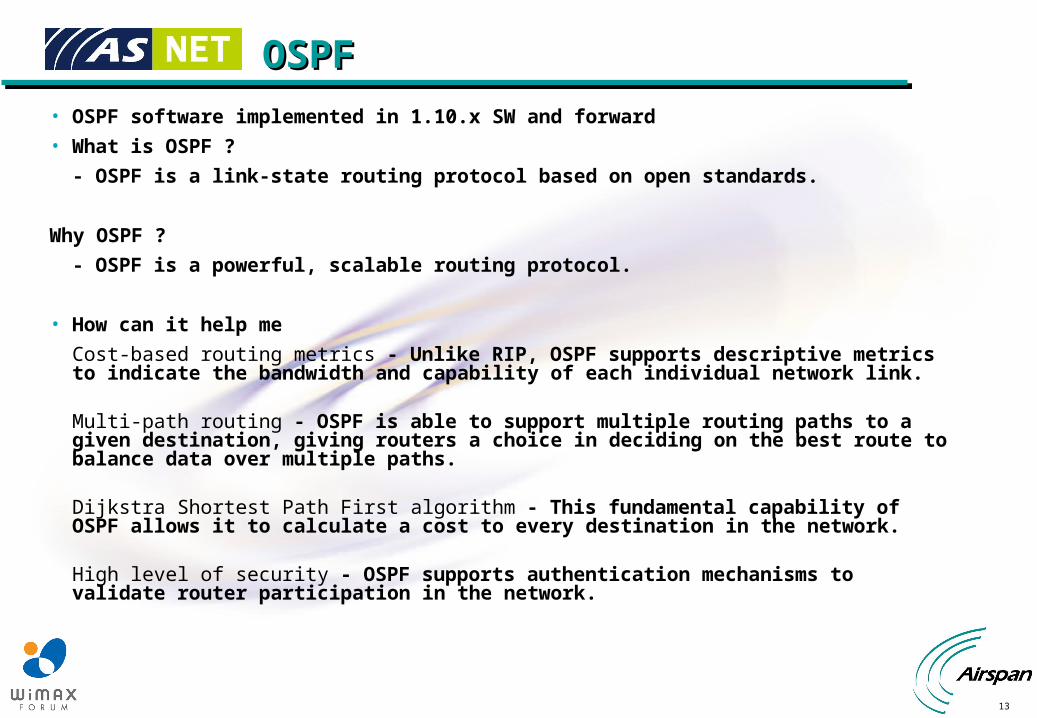
OSPF OSPF
• OSPF software implemented in 1.10.x SW and forward
• What is OSPF ?
- OSPF is a link-state routing protocol based on open standards.
Why OSPF ?
- OSPF is a powerful, scalable routing protocol.
• How can it help me
Cost-based routing metrics - Unlike RIP, OSPF supports descriptive metrics to indicate the bandwidth and capability of each individual network link.
Multi-path routing - OSPF is able to support multiple routing paths to a given destination, giving routers a choice in deciding on the best route to balance data over multiple paths.
Dijkstra Shortest Path First algorithm - This fundamental capability of OSPF allows it to calculate a cost to every destination in the network.
High level of security - OSPF supports authentication mechanisms to validate router participation in the network.

14
Delivering Self-Healing and Dynamic Delivering Self-Healing and Dynamic Rerouting to NetworksRerouting to Networks
• All possible paths are calculated
– Allows change if new route is needed
• One route or up to 4 equal cost routes may be used.
• Best path continuously determined based on Media type, Hello Packets, and other OSPF parameters
Backhaul
Possible Paths
Actual Route

15
LAN or WLAN AREA
Primary and Backup ISPPrimary and Backup ISP
Higher Metric to ISP 2 (Backup)
The Diagram depicts a LAN or WAN using 4 RN800’s , to give access to two ISP’s from the LAN or WLAN area . The Scenario allows for load balancing or using one ISP as backup like we have done.
ISP 2POP
ISP 1POP
Operators who have multiple connections to the Internet may Load balance or use one connection as a backup should the primary and preferred connection go down.
RN800
RN800
RN800
RN800

16
OSPF ConfigurationOSPF Configuration
• This is not an OSPF course, read the OSPF routing manual for more information.
• However a few key points to remember
- All Areas must connect to the backbone area 0, in certain circumstances a virtual link may be used.
• Timers may need adjustment for quicker convergance times
- The timers spf command will change the hold dowm timer
- Dead interval time

17
ExampleExample

18
Example ConfigurationExample Configuration