FlexMulti 1553 Setup Guide - maxt.comdownload.maxt.com/flexmulti/FlexMulti-1553_Setup_Guide.pdf ·...
50
MAX Technologies © 2016 Setup Guide FlexMulti 1553
Transcript of FlexMulti 1553 Setup Guide - maxt.comdownload.maxt.com/flexmulti/FlexMulti-1553_Setup_Guide.pdf ·...
MAX Technologies © 2016
Setup Guide
FlexMulti 1553
MAX Technologies
MAX Technologies © 2016 Page �2
MAX Technologies
Document History
Version Date Note
1.0 10-2016 Initial version
MAX Technologies © 2016 Page �3
MAX Technologies
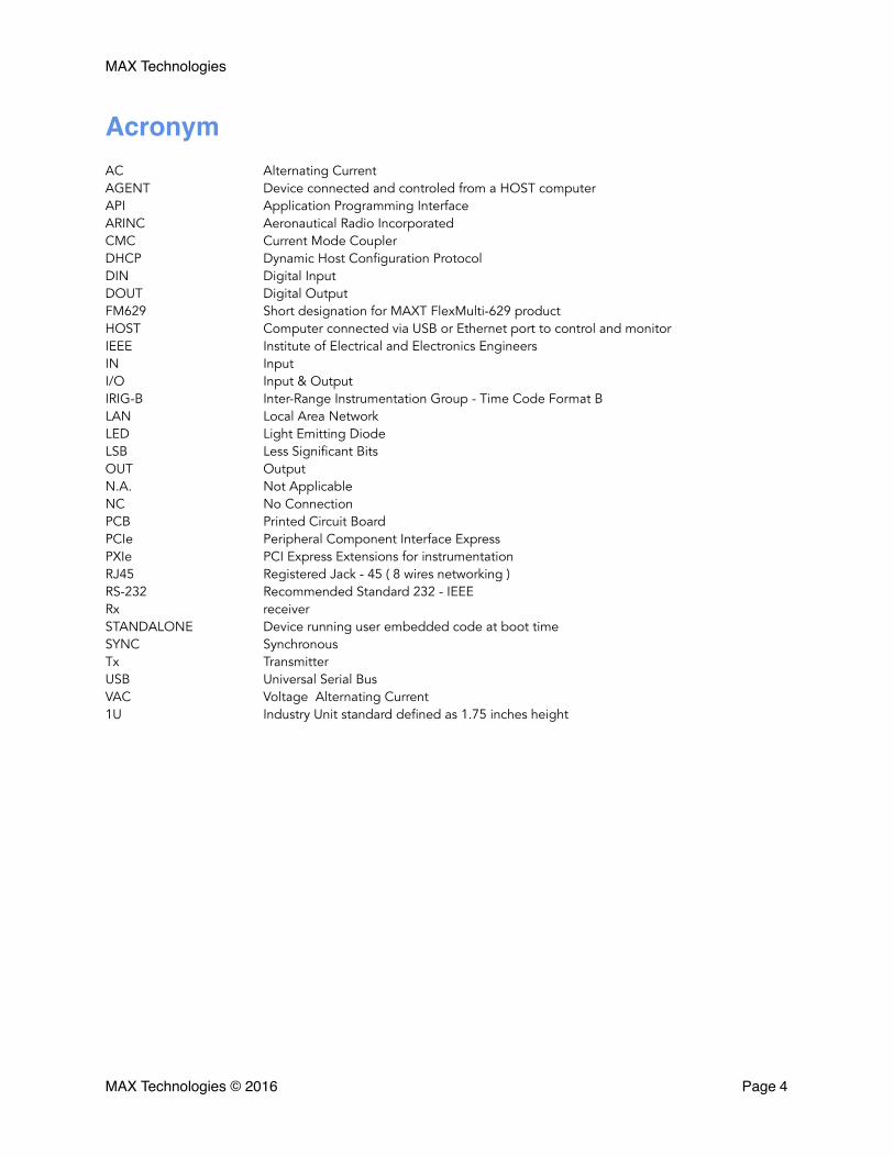
AcronymAC Alternating Current AGENT Device connected and controled from a HOST computer API Application Programming Interface ARINC Aeronautical Radio Incorporated CMC Current Mode Coupler DHCP Dynamic Host Configuration Protocol DIN Digital Input DOUT Digital Output FM629 Short designation for MAXT FlexMulti-629 product HOST Computer connected via USB or Ethernet port to control and monitor IEEE Institute of Electrical and Electronics Engineers IN Input I/O Input & Output IRIG-B Inter-Range Instrumentation Group - Time Code Format B LAN Local Area Network LED Light Emitting Diode LSB Less Significant Bits OUT Output N.A. Not Applicable NC No Connection PCB Printed Circuit Board PCIe Peripheral Component Interface Express PXIe PCI Express Extensions for instrumentation RJ45 Registered Jack - 45 ( 8 wires networking ) RS-232 Recommended Standard 232 - IEEE Rx receiver STANDALONE Device running user embedded code at boot time SYNC Synchronous Tx Transmitter USB Universal Serial Bus VAC Voltage Alternating Current 1U Industry Unit standard defined as 1.75 inches height
MAX Technologies © 2016 Page �4

MAX Technologies
Introduction 7
Unboxing 7
Warning 8
Caution 8
Physical and electrical characteristics 9
Front view 10
Front view details 12
1 - LAN 12
2 - MIL-STD-1553 BUS I/O 12
3 - SYSTEM & Users LED Status 13
4 - Discrete In and Out LED status 13
5 - Discrete I/O 14
6 - Port selectable protocols 16
7 - ASYNC RS-422 / RS-485 / 1553 EBR ports 27
8 - IRIG-B 28
9 - ARINC 429 Tx/Rx ports 29
10 - Sync In / Sync Out 30
Rear view details 32
11 - Main Input Power AC 32
12 - Blowing FAN 32
13 - Optional host interface 32
14 - Ethernet Address LSB 33
15 - Configuration Switches 34
16 - RESET & FACTORY Reset 36
MAX Technologies © 2016 Page �5

MAX Technologies
17 - Chassis GROUND 36
18 - Service serial port 37
Inside Chassis view 38
19-22 MIL-STD-1553 / ARINC 708 Tx Enable 39
23-26 MIL-STD-1553 / ARINC 708 transformer coupled and direct coupled stub selection 39
27 - Extra Ground pins on DISCRETE connector (J13/14/18) 40
28 - DISCRETE I/O Differential Tx 120 Ohm termination (SW20 - S23) 40
29 - DISCRETE I/O Differential Rx 120 Ohm termination (SW24 - S27) 42
30 - SYNC In / Sync Out Terminaison (SW28) 43
31 - DISCRETE Single Rx threshold level +1.6V (SW16 - SW19) 44
32 to 35 - Async channel 0 to 3 Tx/Rx 120 Ohm Termination (SW4 - SW7) 45
Appendix A 46
MAX Technologies © 2016 Page �6
MAX Technologies
IntroductionThank you for purchasing the FlexMulti 1553.
This document provides the information required to configure the FlexMulti for operation in standalone mode or connected to a computer using Ethernet, USB, PCI-Express or PXI-Express.
You will also find details about the various I/O connectors on the front and the back of the unit.
UnboxingThe FlexMulti 1553 box should contain:
• 1 FlexMulti 1553 device
• 1 power cord
• 1 Micro-Sub DB9 cable for synchronization between multiple FlexMulti units
• 1 DB37 adaptor to interface with 28V avionics discrete I/O
• 2 metal brackets with 8 screws for 1U rack mount
• 4 rubber feet with 4 screws to operate the unit on a desk
• 1 USB 3 cable - if the FlexMulti was ordered with the optional USB interface
• 1 PCIe cable with one PCIe x1 host interface cardif the FlexMulti was ordered with the optional PCIe x1 host interface
• 1 PCIe cable with one PCIe x4 host interface card if the FlexMulti was ordered with the optional PCIe x4 host interface
• 1 PCIe cable with one PXIe x4 host interface cardif the FlexMulti was ordered with the optional PXIe x4 host interface
MAX Technologies © 2016 Page �7
MAX Technologies
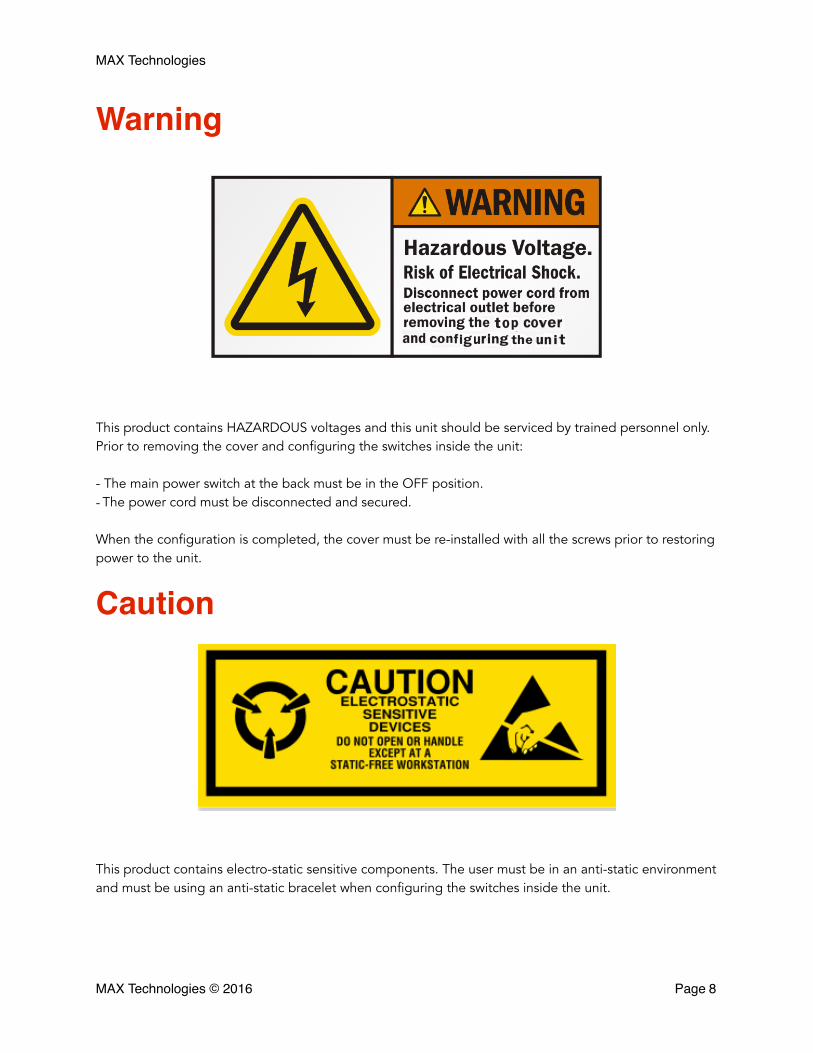
Warning
This product contains HAZARDOUS voltages and this unit should be serviced by trained personnel only. Prior to removing the cover and configuring the switches inside the unit:
- The main power switch at the back must be in the OFF position. - The power cord must be disconnected and secured.
When the configuration is completed, the cover must be re-installed with all the screws prior to restoring power to the unit.
Caution
This product contains electro-static sensitive components. The user must be in an anti-static environment and must be using an anti-static bracelet when configuring the switches inside the unit.
MAX Technologies © 2016 Page �8
MAX Technologies
Physical and electrical characteristics
Size and Weight Height: 1.75 inch (4,45 cm)
Width: 17.375 inch (44,1325 cm)
Depth: 9.375 inch (23,8125 cm)
Weight: 7.7 pounds (3.5 kg)
Electrical and Operating Re-quirements
Line voltage: 100-240V AC
Idle power: 28 W
Power consumption max: 45 W
Frequency: 50Hz to 60Hz
Operating temperature: 50° to 95° F (10° to 35° C)
Storage temperature: -13° to 113° F (-25° to 45° C)
Relative humidity: 0% to 90% noncondensing
Safety CSA-US 60950-1
Emissions Complies with FCC Part 15, ICES-003
MAX Technologies © 2016 Page �9
MAX Technologies
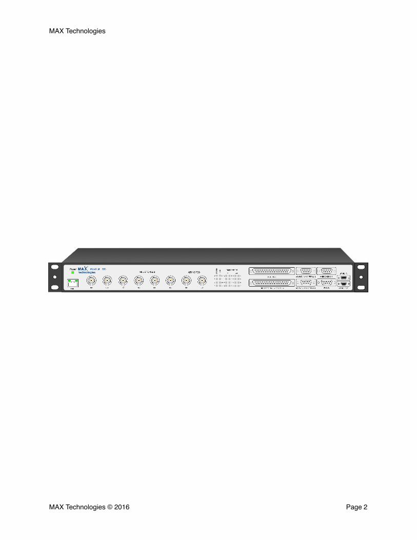
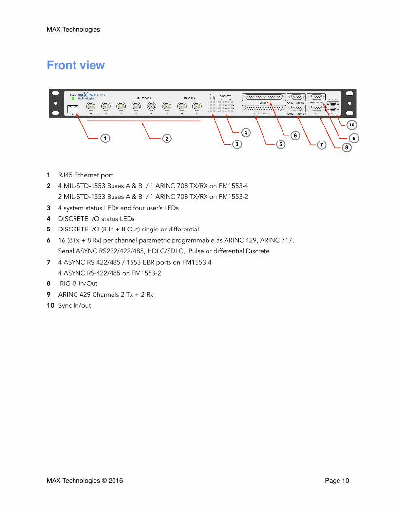
Front view
1 RJ45 Ethernet port
2 4 MIL-STD-1553 Buses A & B / 1 ARINC 708 TX/RX on FM1553-4
2 MIL-STD-1553 Buses A & B / 1 ARINC 708 TX/RX on FM1553-2
3 4 system status LEDs and four user’s LEDs
4 DISCRETE I/O status LEDs
5 DISCRETE I/O (8 In + 8 Out) single or differential
6 16 (8Tx + 8 Rx) per channel parametric programmable as ARINC 429, ARINC 717, Serial ASYNC RS232/422/485, HDLC/SDLC, Pulse or differential Discrete
7 4 ASYNC RS-422/485 / 1553 EBR ports on FM1553-4
4 ASYNC RS-422/485 on FM1553-2
8 IRIG-B In/Out
9 ARINC 429 Channels 2 Tx + 2 Rx
10 Sync In/out
MAX Technologies © 2016 Page �10

MAX Technologies
Rear view
11 Main 110V/220V AC input.
12 Fan ( Blowing out )
13 Optional USB, PCIe or PXIe interface
14 Ethernet LSB address switches ( when not DHCP )
15 Operating mode configuration switch (Standalone, USB, LAN, PCIe)
16 Reset / Factory recovery button.
17 Chassis Ground
18 USB - Serial service port
MAX Technologies © 2016 Page �11
MAX Technologies
Front view details
1 - LAN
A 10/100/1000 Mbps Ethernet port with standard RJ45 connector cable allows the user to control the FlexMulti 1553 over a network or it can be used for network access by a user embedded application.
See section 14 for details about FlexMulti Ethernet IP address setting. See Appendix A for informations about connecting the FlexMulti to LAN or directly to a PC Ethernet port.
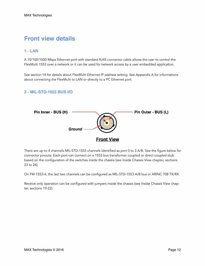
2 - MIL-STD-1553 BUS I/O
There are up to 4 channels MIL-STD-1553 channels identified as port 0 to 3 A/B. See the figure below for connector pinouts. Each port can connect on a 1553 bus transformer coupled or direct coupled stub based on the configuration of the switches inside the chassis (see Inside Chassis View chapter, sections 23 to 26).
On FM-1553-4, the last two channels can be configured as MIL-STD-1553 A/B bus or ARINC 708 TX/RX.
Receive only operation can be configured with jumpers inside the chassis (see Inside Chassis View chap-ter, sections 19-22).
MAX Technologies © 2016 Page �12
MAX Technologies
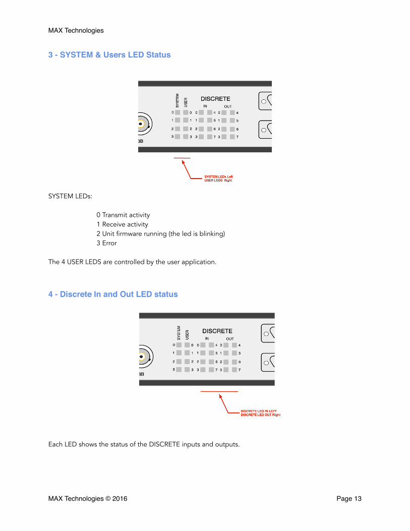
3 - SYSTEM & Users LED Status
SYSTEM LEDs:
0 Transmit activity 1 Receive activity 2 Unit firmware running (the led is blinking) 3 Error
The 4 USER LEDS are controlled by the user application.
4 - Discrete In and Out LED status
Each LED shows the status of the DISCRETE inputs and outputs.
MAX Technologies © 2016 Page �13

MAX Technologies
5 - Discrete I/O
DISCRETE I/O 0-7Pin #
DifferentialSignal
DISCRETE I/O 0-7Pin #
DifferentialSignal
1 INPUT 0 H 20 INPUT 0 L
2 INPUT 1 H 21 INPUT 1 L
3 INPUT 2 H 22 INPUT 2 v
4 INPUT 3 H 23 INPUT 3 L
5 INPUT 4 H 24 INPUT 4 L
6 INPUT 5 H 25 INPUT 5 L
7 INPUT 6 H 26 INPUT 6 L
8 INPUT 7 H 27 INPUT 7 L
9 GROUND 28 GROUND
10 OUTPUT 0 H 29 OUTPUT 0 L
11 OUTPUT 1 H 30 OUTPUT 1 L
12 OUTPUT 2 H 31 OUTPUT 2 L
13 OUTPUT 3 H 32 OUTPUT 3 L
14 OUTPUT 4 H 33 OUTPUT 4 L
15 OUTPUT 5 H 34 OUTPUT 5 L
16 OUTPUT 6 H 35 OUTPUT 6 L
17 OUTPUT 7 H 36 OUTPUT 7 L
18 GROUND (Jumper J20) 37 GROUND (Jumper J24)
19 GROUND (Jumper J22)
MAX Technologies © 2016 Page �14
MAX Technologies
The DB37 bottom connector is for the DISCRETE section with 8 input and 8 output ports. Each port can be used individually as either differential RS-422 or TTL compatible operation. Also 28V compatible avionics discrete operations can be achieved for the 8 Output and 8 Input ports using the supplied DB37 adaptor.
Differential RS-422 discrete operation:
The DB37 bottom connector is for the DISCRETE section with 8 RS-422 differential inputs and outputs. A configuration DIP switch for each differential input and output can terminate the bus with 120 Ohm resistor (see Inside Chassis View chapter, sections 28 and 29).
TTL compatible discrete operation:
Each discrete input and output can also be used for single 5V TTL compatible signal as follows:
TTL compatible output operation is achieved by using only the positive (+) or the inverted (-) Tx output signal with reference to ground. When using as TTL compatible output, the corresponding channel ter-mination DIP switch must be set to OFF (see Inside Chassis View chapter, sections 28 and 29).
TTL compatible Input operation is achieved by using only the positive (+) RX input with reference to ground and setting the corresponding channel 1.6V threshold internal DIP switch to ON (see Inside Chassis View chapter, section 31).
28V avionics discrete operation:
All discrete inpout and output can be used for single 28V avionics compatible signal by using the sup-plied DB37 adaptor and setting the discrete internal DIP switches as follow:
-All channel termination DIP switches must be set to OFF (see Inside Chassis View chapter, sections 28 and 29).
-All channel 1.6V threshold internal DIP switches must be set to ON (see Inside Chassis View chapter, section 31).
When using the DB37 adaptor the inputs and outputs are characterized as follow:
- Input voltage can be in the 0-36V range and the threshold is fixed at 7.7V. Input voltage hysteresis is 200mV.
-Output driver is open collector. The user must add an external pull-up resistor between the output pin and a voltage supply source corresponding to the desired Vout (ex: 28V). The maximum supply voltage is 30V.
MAX Technologies © 2016 Page �15
MAX Technologies
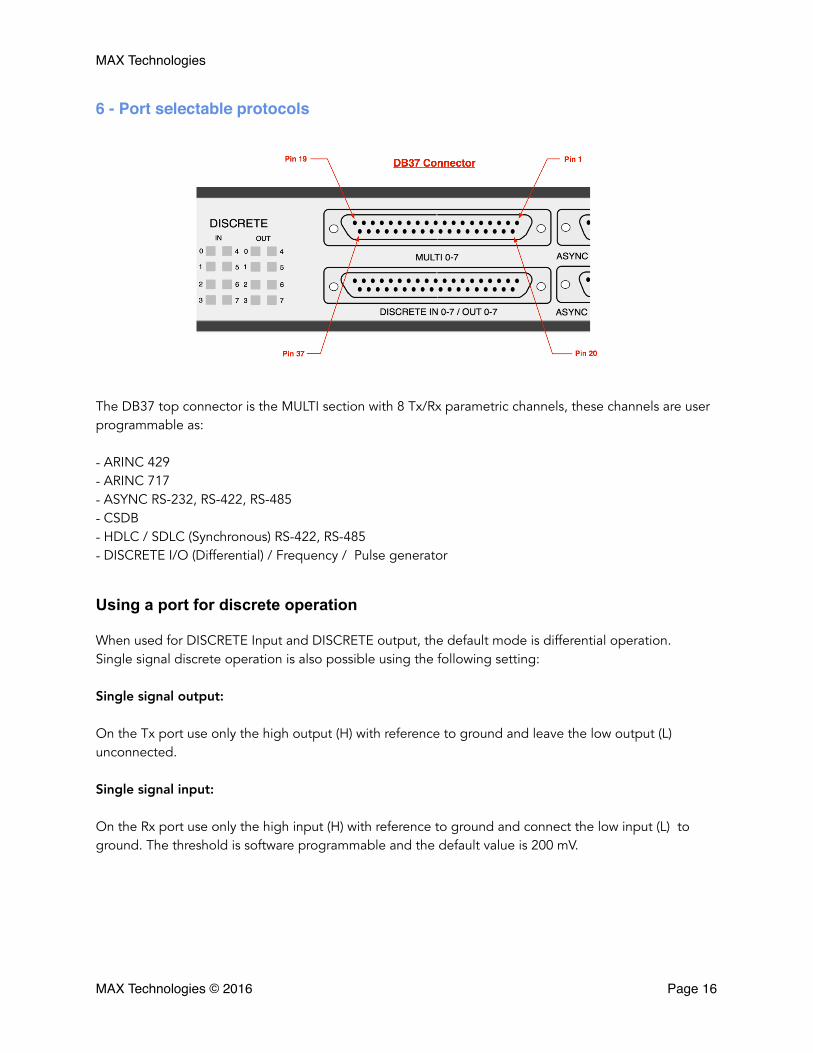
6 - Port selectable protocols
The DB37 top connector is the MULTI section with 8 Tx/Rx parametric channels, these channels are user programmable as:
- ARINC 429 - ARINC 717 - ASYNC RS-232, RS-422, RS-485 - CSDB - HDLC / SDLC (Synchronous) RS-422, RS-485 - DISCRETE I/O (Differential) / Frequency / Pulse generator
Using a port for discrete operation
When used for DISCRETE Input and DISCRETE output, the default mode is differential operation. Single signal discrete operation is also possible using the following setting:
Single signal output:
On the Tx port use only the high output (H) with reference to ground and leave the low output (L) unconnected.
Single signal input:
On the Rx port use only the high input (H) with reference to ground and connect the low input (L) to ground. The threshold is software programmable and the default value is 200 mV.
MAX Technologies © 2016 Page �16
MAX Technologies
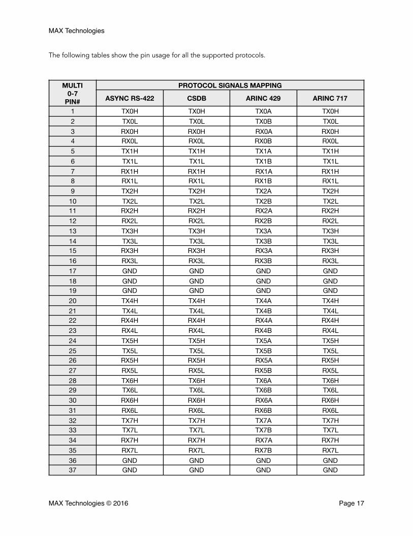
The following tables show the pin usage for all the supported protocols.
MULTI 0-7
PIN#
PROTOCOL SIGNALS MAPPING
ASYNC RS-422 CSDB ARINC 429 ARINC 717
1 TX0H TX0H TX0A TX0H2 TX0L TX0L TX0B TX0L3 RX0H RX0H RX0A RX0H4 RX0L RX0L RX0B RX0L5 TX1H TX1H TX1A TX1H6 TX1L TX1L TX1B TX1L7 RX1H RX1H RX1A RX1H8 RX1L RX1L RX1B RX1L9 TX2H TX2H TX2A TX2H
10 TX2L TX2L TX2B TX2L11 RX2H RX2H RX2A RX2H12 RX2L RX2L RX2B RX2L13 TX3H TX3H TX3A TX3H14 TX3L TX3L TX3B TX3L15 RX3H RX3H RX3A RX3H16 RX3L RX3L RX3B RX3L17 GND GND GND GND18 GND GND GND GND19 GND GND GND GND20 TX4H TX4H TX4A TX4H21 TX4L TX4L TX4B TX4L22 RX4H RX4H RX4A RX4H23 RX4L RX4L RX4B RX4L24 TX5H TX5H TX5A TX5H25 TX5L TX5L TX5B TX5L26 RX5H RX5H RX5A RX5H27 RX5L RX5L RX5B RX5L28 TX6H TX6H TX6A TX6H29 TX6L TX6L TX6B TX6L30 RX6H RX6H RX6A RX6H31 RX6L RX6L RX6B RX6L32 TX7H TX7H TX7A TX7H33 TX7L TX7L TX7B TX7L34 RX7H RX7H RX7A RX7H35 RX7L RX7L RX7B RX7L36 GND GND GND GND37 GND GND GND GND
MAX Technologies © 2016 Page �17

MAX Technologies
MULTI 0-7
PIN#
PROTOCOL SIGNALS MAPPING
DISCRETE IO ASYNC RS-232 ASYNC RS-232 with handshake
ASYNC RS-485 (See Note 1)
1 Output 0 H NC NC Port 0 - TX H2 Output 0 L TX0 Port 0 - TX Port 0 - TX L3 Input 0 H Connect to GND Connect to GND Port 0 - RX H4 Input 0 L RX0 Port 0 - CTS Port 0 - RX L5 Output 1 H NC NC Port 1 - TX H6 Output 1 L TX1 Port 1 - RTS Port 1 - TX L7 Input 1 H Connect to GND Connect to GND Port 1 - RX H8 Input 1 L RX1 Port 0 - RX Port 1 - RX L9 Output 2 H NC NC Port 2 - TX H
10 Output 2 L TX2 Port 1 - TX Port 2 - TX L11 Input 2 H Connect to GND Connect to GND Port 2 - RX H12 Input 2 L RX2 Port 1 - CTS Port 2 - RX L13 Output 3 H NC NC Port 3 - TX H14 Output 3 L TX3 Port 1 - RTS Port 3 - TX L15 Input 3 H Connect to GND Connect to GND Port 3 - RX H16 Input 3 L RX3 Port 1 - RX Port 3 - RX L17 GND GND GND GND18 GND GND GND GND19 GND GND GND GND20 Output 4 H NC NC Port 4 - TX H21 Output 4 L TX4 Port 2 - TX Port 4 - TX L22 Input 4 H Connect to GND Connect to GND Port 4 - RX H23 Input 4 L RX4 Port 2 - CTS Port 4 - RX L24 Output 5 H NC NC Port 5 - TX H25 Output 5 L TX5 Port 2 - RTS Port 5 - TX L26 Input 5 H Connect to GND Connect to GND Port 5 - RX H27 Input 5 L RX5 Port 2 - RX Port 5 - RX L28 Output 6 H NC NC Port 6 - TX H29 Output 6 L TX6 Port 3 - TX Port 6 - TX L30 Input 6 H Connect to GND Connect to GND Port 6 - RX H31 Input 6 L RX6 Port 3 - CTS Port 6 - RX L32 Output 7 H NC NC Port 7 - TX H33 Output 7 L TX3 Port 3 - RTS Port 7 - TX L34 Input 7 H Connect to GND Connect to GND Port 7 - RX H35 Input 7 L RX3 Port 3 - RX Port 7 - RX L36 GND GND GND GND37 GND GND GND GND
NOTE 1: For RS-485 operation connect Port TX lines to the corresponding Port RX lines
MAX Technologies © 2016 Page �18
MAX Technologies
MULTI 0-7
PIN#
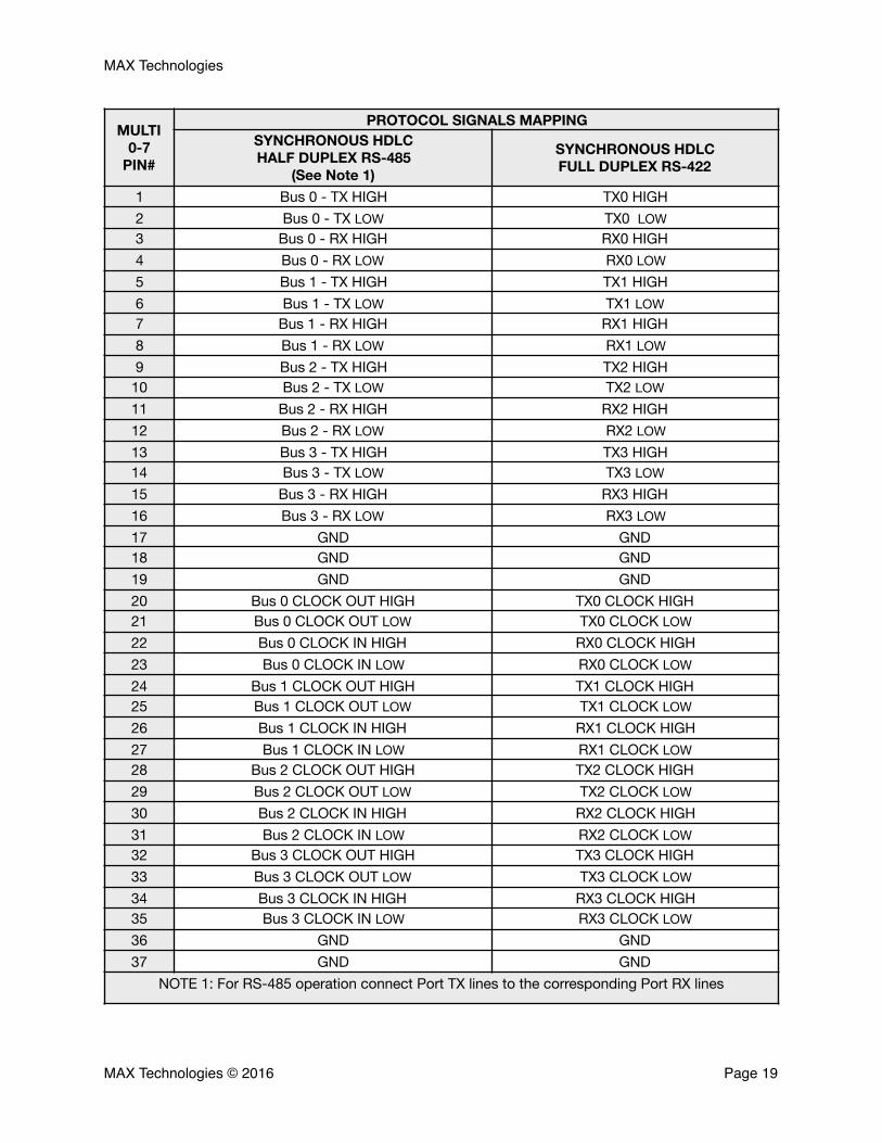
PROTOCOL SIGNALS MAPPINGSYNCHRONOUS HDLC HALF DUPLEX RS-485
(See Note 1)
SYNCHRONOUS HDLC FULL DUPLEX RS-422
1 Bus 0 - TX HIGH TX0 HIGH2 Bus 0 - TX LOW TX0 LOW3 Bus 0 - RX HIGH RX0 HIGH4 Bus 0 - RX LOW RX0 LOW5 Bus 1 - TX HIGH TX1 HIGH6 Bus 1 - TX LOW TX1 LOW7 Bus 1 - RX HIGH RX1 HIGH8 Bus 1 - RX LOW RX1 LOW9 Bus 2 - TX HIGH TX2 HIGH
10 Bus 2 - TX LOW TX2 LOW11 Bus 2 - RX HIGH RX2 HIGH12 Bus 2 - RX LOW RX2 LOW13 Bus 3 - TX HIGH TX3 HIGH14 Bus 3 - TX LOW TX3 LOW15 Bus 3 - RX HIGH RX3 HIGH16 Bus 3 - RX LOW RX3 LOW17 GND GND18 GND GND19 GND GND20 Bus 0 CLOCK OUT HIGH TX0 CLOCK HIGH21 Bus 0 CLOCK OUT LOW TX0 CLOCK LOW22 Bus 0 CLOCK IN HIGH RX0 CLOCK HIGH23 Bus 0 CLOCK IN LOW RX0 CLOCK LOW24 Bus 1 CLOCK OUT HIGH TX1 CLOCK HIGH25 Bus 1 CLOCK OUT LOW TX1 CLOCK LOW26 Bus 1 CLOCK IN HIGH RX1 CLOCK HIGH27 Bus 1 CLOCK IN LOW RX1 CLOCK LOW28 Bus 2 CLOCK OUT HIGH TX2 CLOCK HIGH29 Bus 2 CLOCK OUT LOW TX2 CLOCK LOW30 Bus 2 CLOCK IN HIGH RX2 CLOCK HIGH31 Bus 2 CLOCK IN LOW RX2 CLOCK LOW32 Bus 3 CLOCK OUT HIGH TX3 CLOCK HIGH33 Bus 3 CLOCK OUT LOW TX3 CLOCK LOW34 Bus 3 CLOCK IN HIGH RX3 CLOCK HIGH35 Bus 3 CLOCK IN LOW RX3 CLOCK LOW36 GND GND37 GND GND
NOTE 1: For RS-485 operation connect Port TX lines to the corresponding Port RX lines
MAX Technologies © 2016 Page �19
MAX Technologies
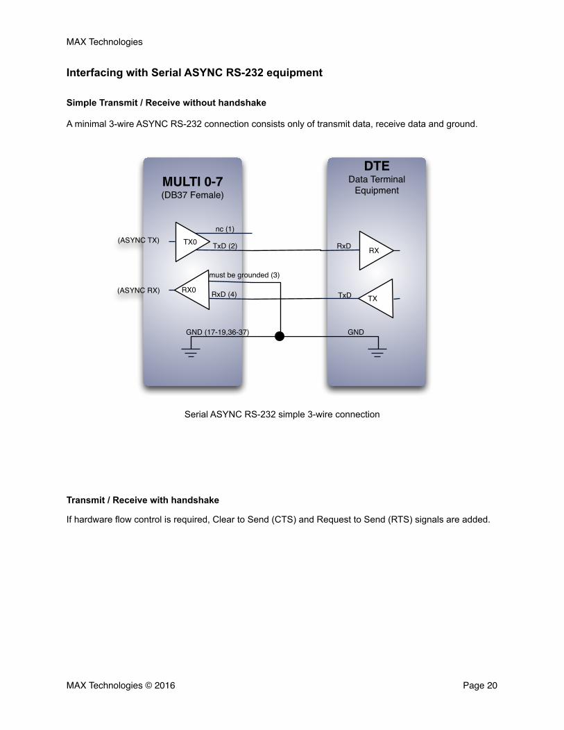
Interfacing with Serial ASYNC RS-232 equipment
Simple Transmit / Receive without handshake
A minimal 3-wire ASYNC RS-232 connection consists only of transmit data, receive data and ground.
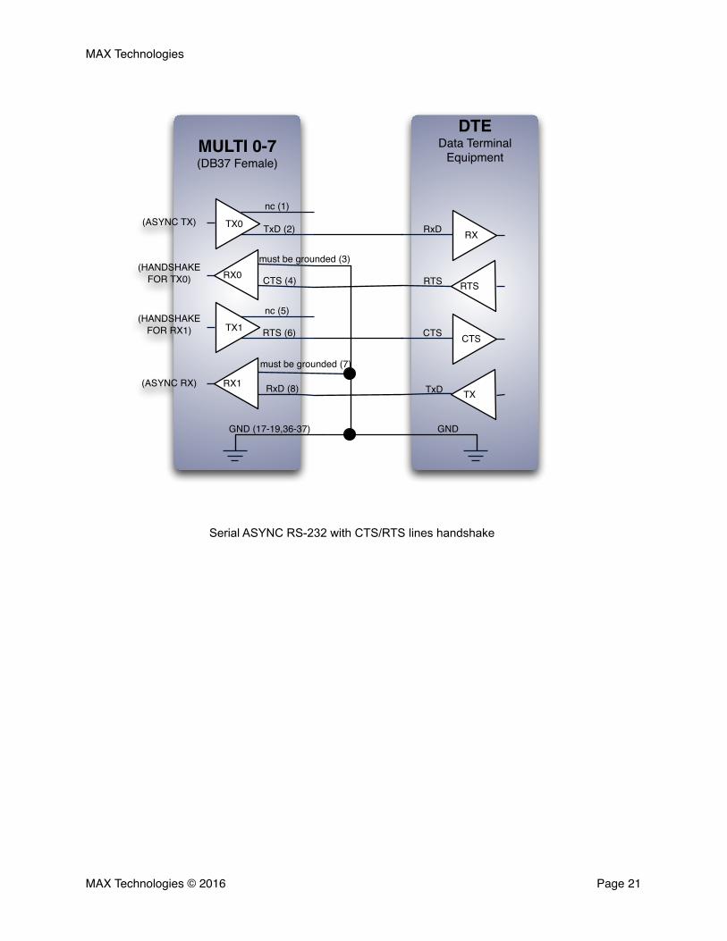
Transmit / Receive with handshake
If hardware flow control is required, Clear to Send (CTS) and Request to Send (RTS) signals are added.
MAX Technologies © 2016 Page �20
Serial ASYNC RS-232 simple 3-wire connection
MULTI 0-7(DB37 Female)
DTEData Terminal
Equipment
GND (17-19,36-37) GND
TXRX0
TxDRxD (4)
TX0RX
nc (1)
TxD (2) RxD
(ASYNC RX)
(ASYNC TX)
must be grounded (3)
MAX Technologies
MAX Technologies © 2016 Page �21
Serial ASYNC RS-232 with CTS/RTS lines handshake
DTEData Terminal
EquipmentMULTI 0-7(DB37 Female)
(ASYNC RX)
(HANDSHAKE FOR RX1)
(ASYNC TX)
(HANDSHAKE FOR TX0)
TX1CTSRTS (6) CTS
TX0RXTxD (2) RxD
RTSRX0 RTS
must be grounded (3)
CTS (4)
GNDGND (17-19,36-37)
RxD (8) TxDRX1TX
nc (1)
nc (5)
must be grounded (7)
MAX Technologies
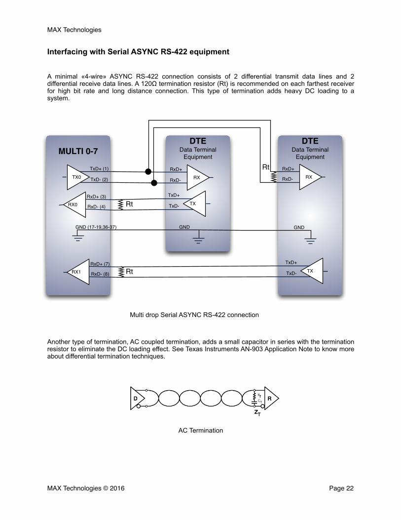
Interfacing with Serial ASYNC RS-422 equipment
A minimal «4-wire» ASYNC RS-422 connection consists of 2 differential transmit data lines and 2 differential receive data lines. A 120Ω termination resistor (Rt) is recommended on each farthest receiver for high bit rate and long distance connection. This type of termination adds heavy DC loading to a system.
Another type of termination, AC coupled termination, adds a small capacitor in series with the termination resistor to eliminate the DC loading effect. See Texas Instruments AN-903 Application Note to know more about differential termination techniques.
MAX Technologies © 2016 Page �22
Multi drop Serial ASYNC RS-422 connection
DTEData Terminal
Equipment
DTEData Terminal
EquipmentMULTI 0-7
RxD- (8)
RxD+ (7)RX1 Rt TX
TxD+
TxD-
RxD- (4)
RxD+ (3)RX0 Rt TX
TxD+
TxD-
RtTxD- (2)
TxD+ (1)TX0
GNDGND (17-19,36-37)
RXRxD+
RxD-
GND
RXRxD+
RxD-
AC Termination
MAX Technologies
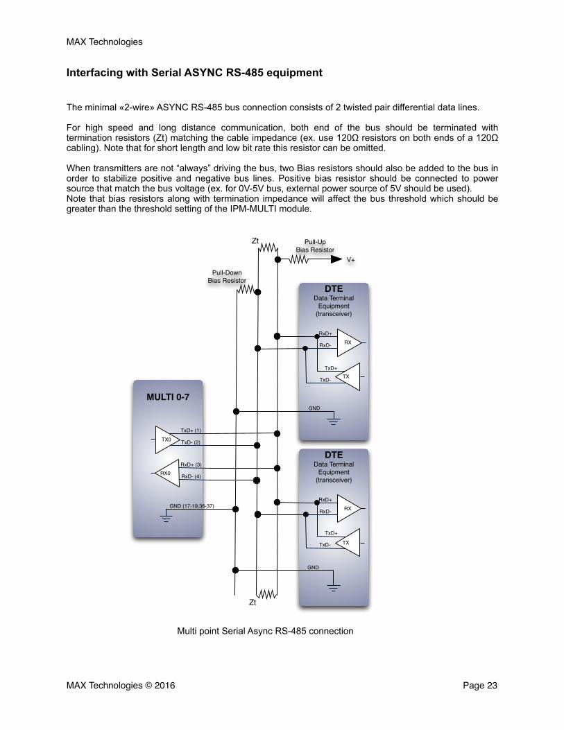
Interfacing with Serial ASYNC RS-485 equipment
The minimal «2-wire» ASYNC RS-485 bus connection consists of 2 twisted pair differential data lines.
For high speed and long distance communication, both end of the bus should be terminated with termination resistors (Zt) matching the cable impedance (ex. use 120Ω resistors on both ends of a 120Ω cabling). Note that for short length and low bit rate this resistor can be omitted.
When transmitters are not “always” driving the bus, two Bias resistors should also be added to the bus in order to stabilize positive and negative bus lines. Positive bias resistor should be connected to power source that match the bus voltage (ex. for 0V-5V bus, external power source of 5V should be used). Note that bias resistors along with termination impedance will affect the bus threshold which should be greater than the threshold setting of the IPM-MULTI module.
MAX Technologies © 2016 Page �23
Multi point Serial Async RS-485 connection
DTEData Terminal
Equipment(transceiver)
MULTI 0-7
DTEData Terminal
Equipment(transceiver)
TxD- (2)
TxD+ (1)TX0
RxD- (4)
RxD+ (3)RX0
GND
GND (17-19,36-37)
TX
RXRxD+
RxD-
TxD+
TxD-
TX
RXRxD+
RxD-
TxD+
TxD-
Zt
Zt
GND
Pull-UpBias Resistor
Pull-Down Bias Resistor
V+
MAX Technologies
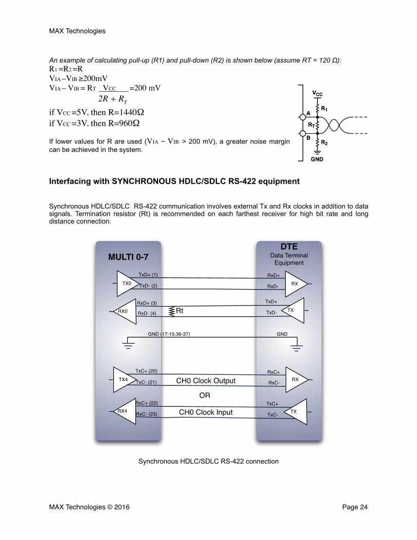
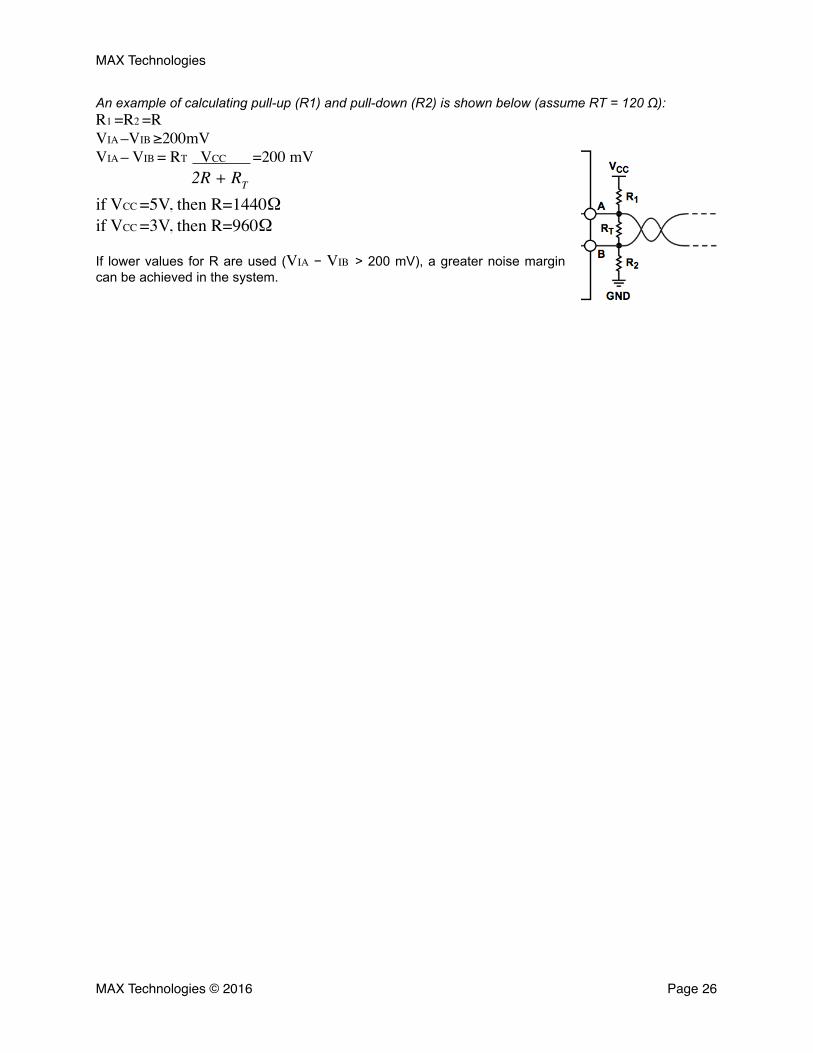
An example of calculating pull-up (R1) and pull-down (R2) is shown below (assume RT = 120 Ω): R1 =R2 =RVIA –VIB ≥200mVVIA – VIB = RT VCC =200 mV
2R + RT
if VCC =5V, then R=1440Ω if VCC =3V, then R=960Ω
If lower values for R are used (VIA − VIB > 200 mV), a greater noise margin can be achieved in the system.
Interfacing with SYNCHRONOUS HDLC/SDLC RS-422 equipment
Synchronous HDLC/SDLC RS-422 communication involves external Tx and Rx clocks in addition to data signals. Termination resistor (Rt) is recommended on each farthest receiver for high bit rate and long distance connection.
MAX Technologies © 2016 Page �24
DTEData Terminal
EquipmentMULTI 0-7
RxD- (4)
RxD+ (3)RX0 Rt TX
TxD+
TxD-
TxD- (2)
TxD+ (1)TX0
GNDGND (17-19,36-37)
RXRxD+
RxD-
TxC- (21)
TxC+ (20)TX4
RxC- (23)
RxC+ (22)RX4
CH0 Clock Output
CH0 Clock Input
OR
RxC+
RxC-
TX
RX
TxC+
TxC-
Synchronous HDLC/SDLC RS-422 connection
MAX Technologies
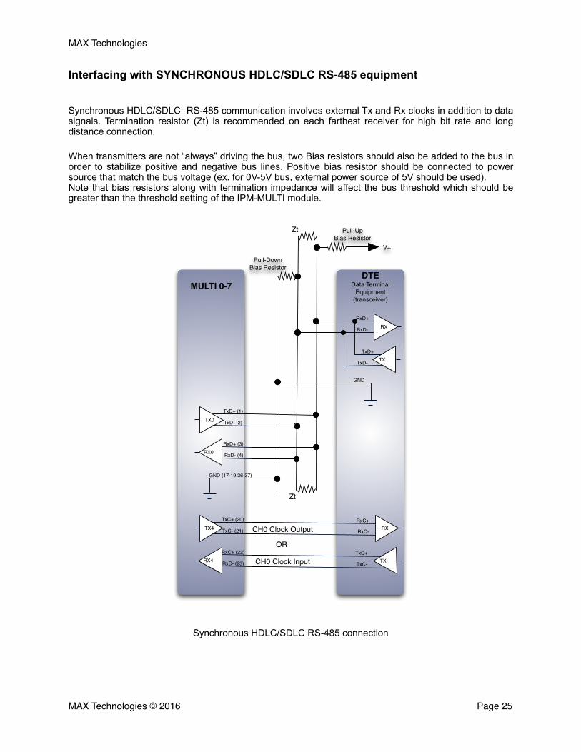
Interfacing with SYNCHRONOUS HDLC/SDLC RS-485 equipment
Synchronous HDLC/SDLC RS-485 communication involves external Tx and Rx clocks in addition to data signals. Termination resistor (Zt) is recommended on each farthest receiver for high bit rate and long distance connection.
When transmitters are not “always” driving the bus, two Bias resistors should also be added to the bus in order to stabilize positive and negative bus lines. Positive bias resistor should be connected to power source that match the bus voltage (ex. for 0V-5V bus, external power source of 5V should be used). Note that bias resistors along with termination impedance will affect the bus threshold which should be greater than the threshold setting of the IPM-MULTI module.
MAX Technologies © 2016 Page �25
Synchronous HDLC/SDLC RS-485 connection
DTEData Terminal
Equipment(transceiver)
MULTI 0-7
TxD- (2)
TxD+ (1)TX0
RxD- (4)
RxD+ (3)RX0
GND
GND (17-19,36-37)
TX
RXRxD+
RxD-
TxD+
TxD-
Zt
Zt
Pull-UpBias Resistor
Pull-Down Bias Resistor
V+
TxC- (21)
TxC+ (20)TX4
RxC- (23)
RxC+ (22)RX4
CH0 Clock Output
CH0 Clock Input
OR
RxC+
RxC-
TX
RX
TxC+
TxC-
MAX Technologies
An example of calculating pull-up (R1) and pull-down (R2) is shown below (assume RT = 120 Ω): R1 =R2 =RVIA –VIB ≥200mVVIA – VIB = RT VCC =200 mV
2R + RT
if VCC =5V, then R=1440Ω if VCC =3V, then R=960Ω
If lower values for R are used (VIA − VIB > 200 mV), a greater noise margin can be achieved in the system.
MAX Technologies © 2016 Page �26
MAX Technologies
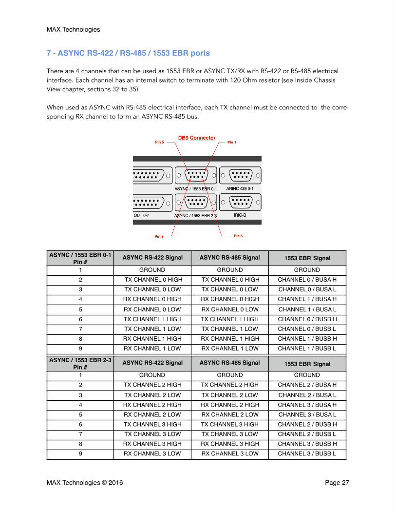
7 - ASYNC RS-422 / RS-485 / 1553 EBR ports
There are 4 channels that can be used as 1553 EBR or ASYNC TX/RX with RS-422 or RS-485 electrical interface. Each channel has an internal switch to terminate with 120 Ohm resistor (see Inside Chassis View chapter, sections 32 to 35).
When used as ASYNC with RS-485 electrical interface, each TX channel must be connected to the corre-sponding RX channel to form an ASYNC RS-485 bus.
ASYNC / 1553 EBR 0-1 Pin #
ASYNC RS-422 Signal ASYNC RS-485 Signal 1553 EBR Signal
1 GROUND GROUND GROUND2 TX CHANNEL 0 HIGH TX CHANNEL 0 HIGH CHANNEL 0 / BUSA H3 TX CHANNEL 0 LOW TX CHANNEL 0 LOW CHANNEL 0 / BUSA L4 RX CHANNEL 0 HIGH RX CHANNEL 0 HIGH CHANNEL 1 / BUSA H5 RX CHANNEL 0 LOW RX CHANNEL 0 LOW CHANNEL 1 / BUSA L6 TX CHANNEL 1 HIGH TX CHANNEL 1 HIGH CHANNEL 0 / BUSB H7 TX CHANNEL 1 LOW TX CHANNEL 1 LOW CHANNEL 0 / BUSB L8 RX CHANNEL 1 HIGH RX CHANNEL 1 HIGH CHANNEL 1 / BUSB H9 RX CHANNEL 1 LOW RX CHANNEL 1 LOW CHANNEL 1 / BUSB L
ASYNC / 1553 EBR 2-3 Pin #
ASYNC RS-422 Signal ASYNC RS-485 Signal 1553 EBR Signal
1 GROUND GROUND GROUND2 TX CHANNEL 2 HIGH TX CHANNEL 2 HIGH CHANNEL 2 / BUSA H3 TX CHANNEL 2 LOW TX CHANNEL 2 LOW CHANNEL 2 / BUSA L4 RX CHANNEL 2 HIGH RX CHANNEL 2 HIGH CHANNEL 3 / BUSA H5 RX CHANNEL 2 LOW RX CHANNEL 2 LOW CHANNEL 3 / BUSA L6 TX CHANNEL 3 HIGH TX CHANNEL 3 HIGH CHANNEL 2 / BUSB H7 TX CHANNEL 3 LOW TX CHANNEL 3 LOW CHANNEL 2 / BUSB L8 RX CHANNEL 3 HIGH RX CHANNEL 3 HIGH CHANNEL 3 / BUSB H9 RX CHANNEL 3 LOW RX CHANNEL 3 LOW CHANNEL 3 / BUSB L
MAX Technologies © 2016 Page �27
MAX Technologies
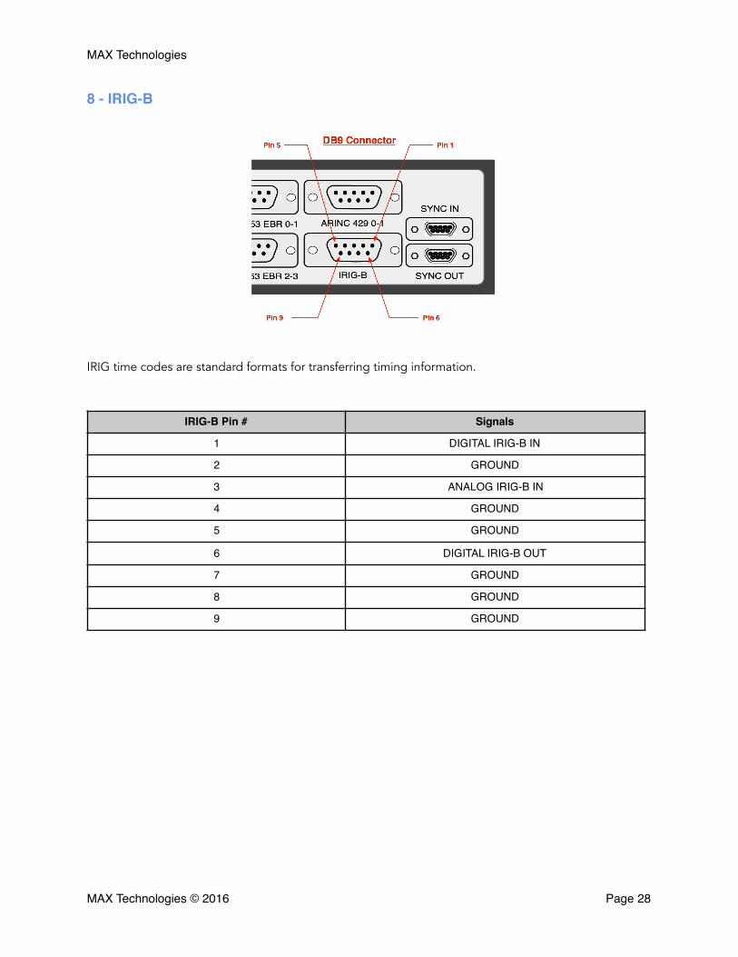
8 - IRIG-B
IRIG time codes are standard formats for transferring timing information.
IRIG-B Pin # Signals
1 DIGITAL IRIG-B IN
2 GROUND
3 ANALOG IRIG-B IN
4 GROUND
5 GROUND
6 DIGITAL IRIG-B OUT
7 GROUND
8 GROUND
9 GROUND
MAX Technologies © 2016 Page �28

MAX Technologies
9 - ARINC 429 Tx/Rx ports
There are 4 fixed ARINC 429 ports, 2 Tx + 2 Rx.
ARINC 429 0-1 Pin # Signal1 GROUND2 TX0A3 TX0B4 RX0A5 RX0B6 TX1A7 TX1B8 RX1A9 RX1B
MAX Technologies © 2016 Page �29
MAX Technologies
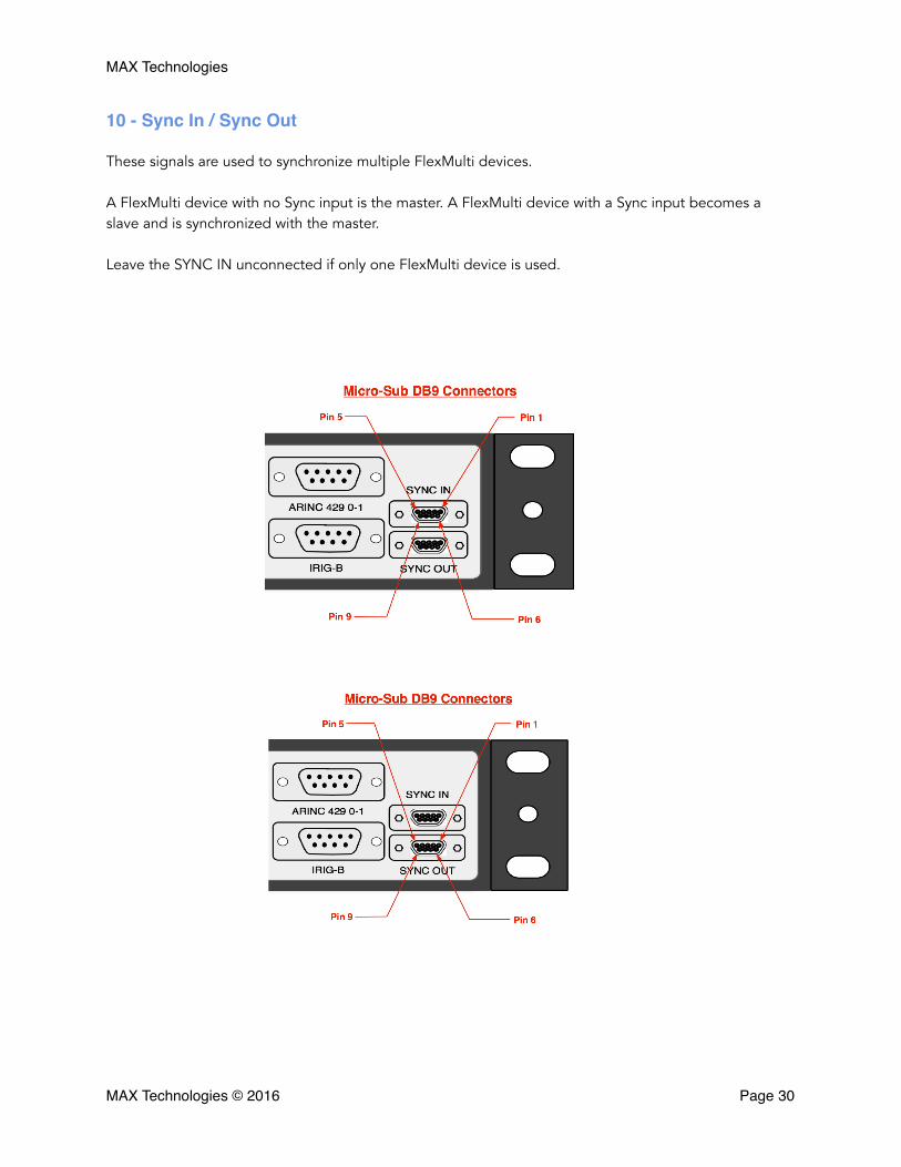
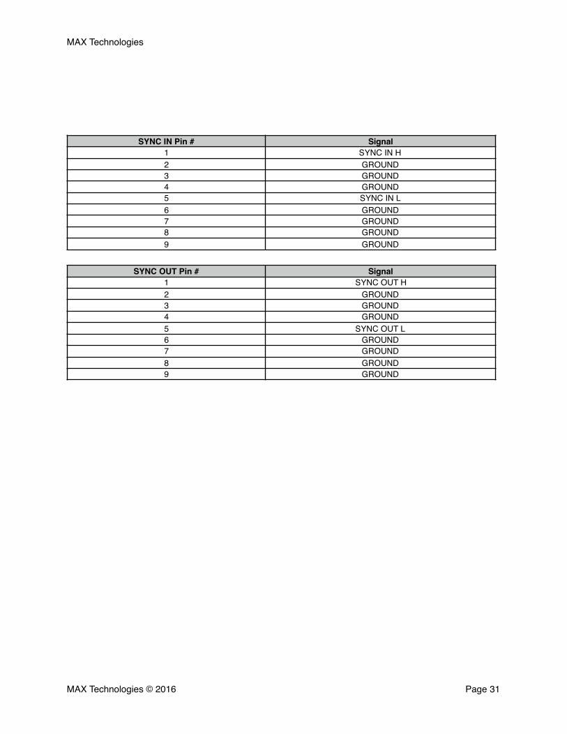
10 - Sync In / Sync Out
These signals are used to synchronize multiple FlexMulti devices.
A FlexMulti device with no Sync input is the master. A FlexMulti device with a Sync input becomes a slave and is synchronized with the master.
Leave the SYNC IN unconnected if only one FlexMulti device is used.
MAX Technologies © 2016 Page �30
MAX Technologies
SYNC IN Pin # Signal1 SYNC IN H2 GROUND3 GROUND4 GROUND5 SYNC IN L6 GROUND7 GROUND8 GROUND9 GROUND
SYNC OUT Pin # Signal1 SYNC OUT H2 GROUND3 GROUND4 GROUND5 SYNC OUT L6 GROUND7 GROUND8 GROUND9 GROUND
MAX Technologies © 2016 Page �31
MAX Technologies
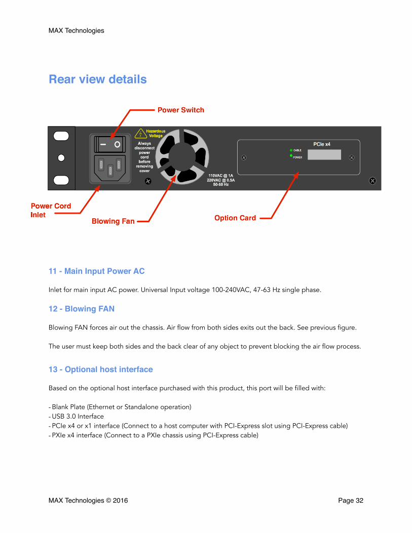
Rear view details
11 - Main Input Power AC
Inlet for main input AC power. Universal Input voltage 100-240VAC, 47-63 Hz single phase.
12 - Blowing FAN
Blowing FAN forces air out the chassis. Air flow from both sides exits out the back. See previous figure.
The user must keep both sides and the back clear of any object to prevent blocking the air flow process.
13 - Optional host interface
Based on the optional host interface purchased with this product, this port will be filled with:
- Blank Plate (Ethernet or Standalone operation) - USB 3.0 Interface - PCIe x4 or x1 interface (Connect to a host computer with PCI-Express slot using PCI-Express cable) - PXIe x4 interface (Connect to a PXIe chassis using PCI-Express cable)
MAX Technologies © 2016 Page �32
MAX Technologies
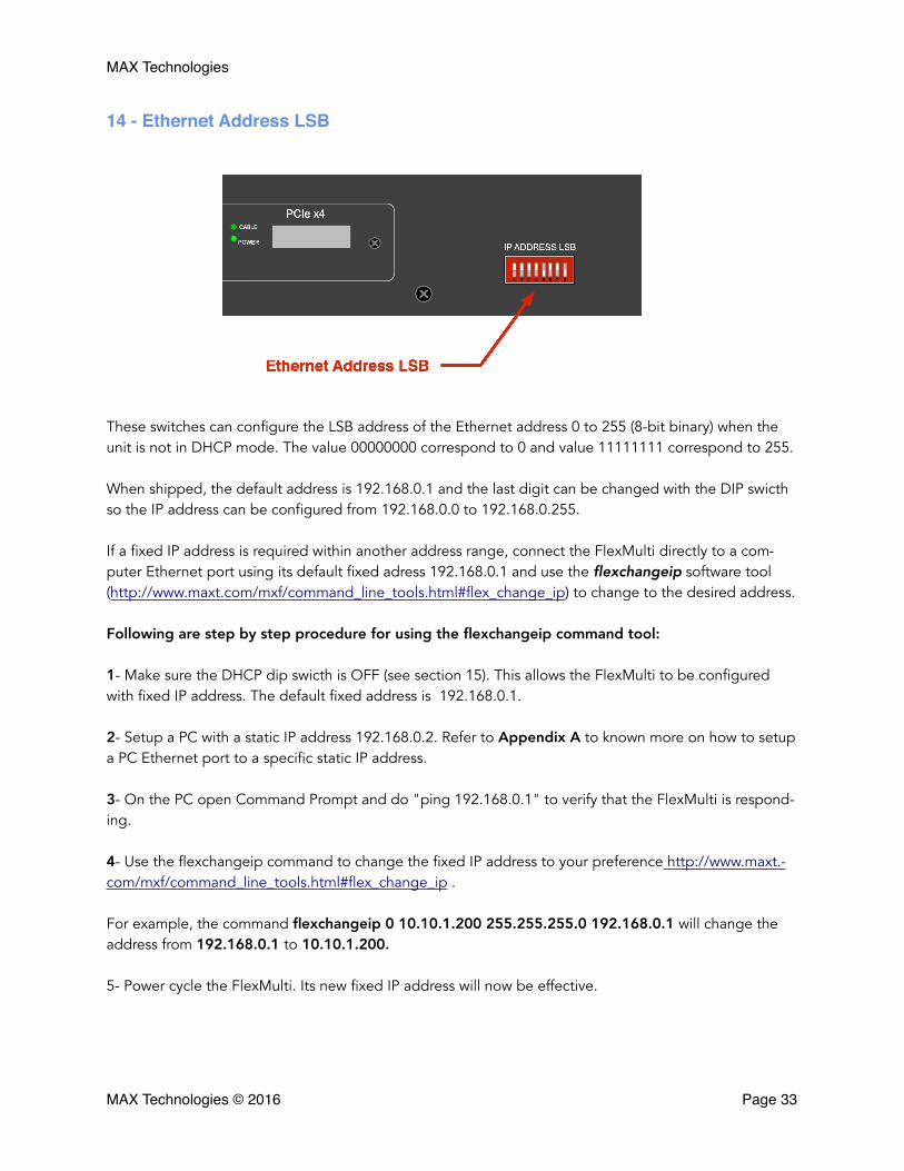
14 - Ethernet Address LSB
These switches can configure the LSB address of the Ethernet address 0 to 255 (8-bit binary) when the unit is not in DHCP mode. The value 00000000 correspond to 0 and value 11111111 correspond to 255.
When shipped, the default address is 192.168.0.1 and the last digit can be changed with the DIP swicth so the IP address can be configured from 192.168.0.0 to 192.168.0.255.
If a fixed IP address is required within another address range, connect the FlexMulti directly to a com-puter Ethernet port using its default fixed adress 192.168.0.1 and use the flexchangeip software tool (http://www.maxt.com/mxf/command_line_tools.html#flex_change_ip) to change to the desired address.
Following are step by step procedure for using the flexchangeip command tool:
1- Make sure the DHCP dip swicth is OFF (see section 15). This allows the FlexMulti to be configured with fixed IP address. The default fixed address is 192.168.0.1.
2- Setup a PC with a static IP address 192.168.0.2. Refer to Appendix A to known more on how to setup a PC Ethernet port to a specific static IP address.
3- On the PC open Command Prompt and do "ping 192.168.0.1" to verify that the FlexMulti is respond-ing.
4- Use the flexchangeip command to change the fixed IP address to your preference http://www.maxt.-com/mxf/command_line_tools.html#flex_change_ip .
For example, the command flexchangeip 0 10.10.1.200 255.255.255.0 192.168.0.1 will change the address from 192.168.0.1 to 10.10.1.200.
5- Power cycle the FlexMulti. Its new fixed IP address will now be effective.
MAX Technologies © 2016 Page �33
MAX Technologies
In this example, the last digit 200 will be overriden by the dip switches, so if you have two FlexMulti on a LAN that must be configured at fixed IP address 10.10.10.200 and 10.10.10.201 you just have to setup the dip-switch on the first unit to "200" and the second unit to "201".
The FlexMulti can also be configured to acquire its IP address from a DHCP server on the LAN instead of using a fixed IP address.
The DIP-SWITCH named DHCP is for such purpose. Using DHCP, when power ON the FlexMulti will ac-quire its IP address dynamically frorm a DHCP server if present on the LAN instead of using its fixed IP address.
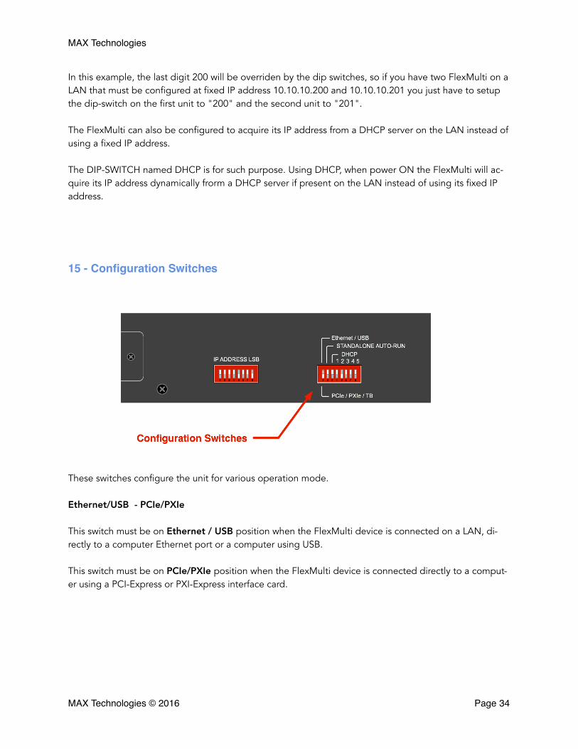
15 - Configuration Switches
These switches configure the unit for various operation mode.
Ethernet/USB - PCIe/PXIe
This switch must be on Ethernet / USB position when the FlexMulti device is connected on a LAN, di-rectly to a computer Ethernet port or a computer using USB.
This switch must be on PCIe/PXIe position when the FlexMulti device is connected directly to a comput-er using a PCI-Express or PXI-Express interface card.
MAX Technologies © 2016 Page �34
MAX Technologies
STANDALONE AUTORUN
This switch must be on STANDALONE AUTORUN position when the FlexMulti device runs in standalone mode from a power-on. When running standalone, the Ethernet port can be used by the embedded ap-plication.
DHCP
This switch must be on DHCP position when the FlexMulti device is connected to a LAN to acquire its IP address dynamically from the DHCP server on the network, otherwise the FlexMulti must be configured using a fixed IP address (see section 14).
1, 2, 3 ,4, 5
These five switches are unused.
MAX Technologies © 2016 Page �35
MAX Technologies
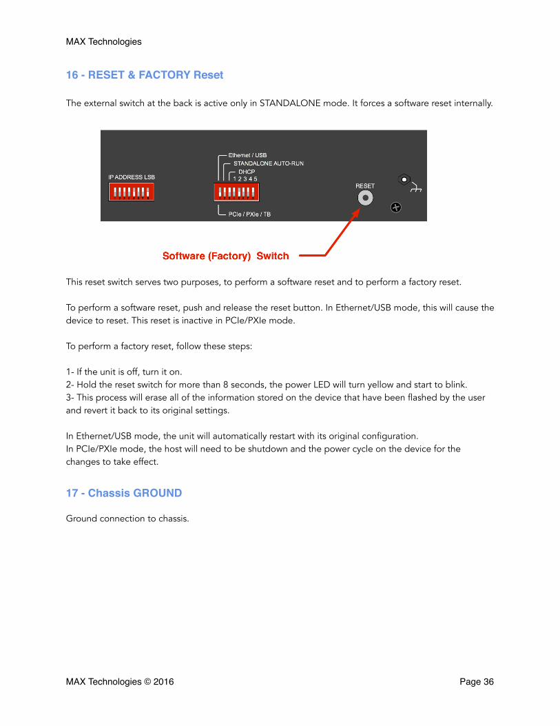
16 - RESET & FACTORY Reset
The external switch at the back is active only in STANDALONE mode. It forces a software reset internally.
This reset switch serves two purposes, to perform a software reset and to perform a factory reset.
To perform a software reset, push and release the reset button. In Ethernet/USB mode, this will cause the device to reset. This reset is inactive in PCIe/PXIe mode.
To perform a factory reset, follow these steps:
1- If the unit is off, turn it on. 2- Hold the reset switch for more than 8 seconds, the power LED will turn yellow and start to blink. 3- This process will erase all of the information stored on the device that have been flashed by the user and revert it back to its original settings.
In Ethernet/USB mode, the unit will automatically restart with its original configuration. In PCIe/PXIe mode, the host will need to be shutdown and the power cycle on the device for the changes to take effect.
17 - Chassis GROUND
Ground connection to chassis.
MAX Technologies © 2016 Page �36
MAX Technologies
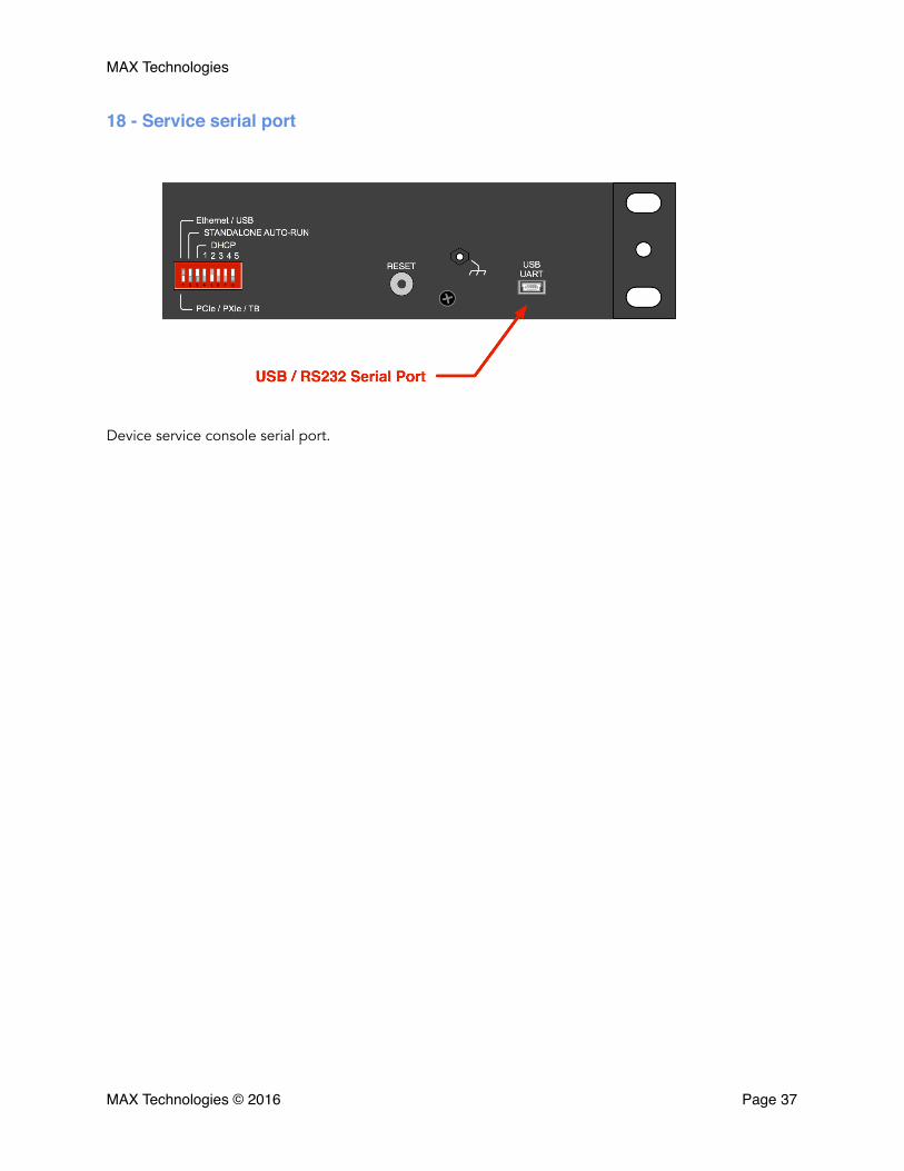
18 - Service serial port
Device service console serial port.
MAX Technologies © 2016 Page �37
MAX Technologies
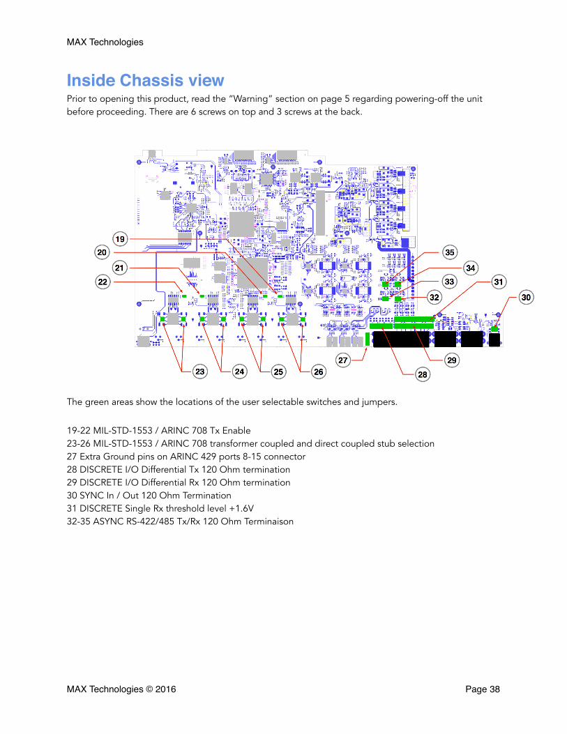
Inside Chassis viewPrior to opening this product, read the “Warning” section on page 5 regarding powering-off the unit before proceeding. There are 6 screws on top and 3 screws at the back.
The green areas show the locations of the user selectable switches and jumpers.
19-22 MIL-STD-1553 / ARINC 708 Tx Enable 23-26 MIL-STD-1553 / ARINC 708 transformer coupled and direct coupled stub selection 27 Extra Ground pins on ARINC 429 ports 8-15 connector 28 DISCRETE I/O Differential Tx 120 Ohm termination 29 DISCRETE I/O Differential Rx 120 Ohm termination 30 SYNC In / Out 120 Ohm Termination 31 DISCRETE Single Rx threshold level +1.6V 32-35 ASYNC RS-422/485 Tx/Rx 120 Ohm Terminaison
MAX Technologies © 2016 Page �38

MAX Technologies
19-22 MIL-STD-1553 / ARINC 708 Tx Enable
User can disable MIL-STD-1553 transmission (Rx Only) when a jumper is removed.
23-26 MIL-STD-1553 / ARINC 708 transformer coupled and direct coupled stub se-lection
Image below for channel 0, same for channel 1,2 and 3. The switch is active (ON) when it is towards the dot.
Jumper Protocol
J10 MIL-STD-1553 Channel 0A & 0B
J11 MIL-STD-1553 Channel 1A & 1B
J9 MIL-STD-1553 Channel 2A & 2B
J12 MIL-STD-1553 / ARINC 708 Channel 3A & 3B
Switch/ Bus Direct TransformerSW12 & SW8 - 1553Tx/Rx 0 BusA & Bus B ON OFFSW13 & SW9 - 1553Tx/Rx 1 BusA & Bus B ON OFF
SW14 & SW10 - 1553Tx/Rx 2 BusA & Bus B ON OFFSW15 & SW11 - 1553Tx/Rx 3 BusA & Bus B ON OFF
MAX Technologies © 2016 Page �39
MAX Technologies
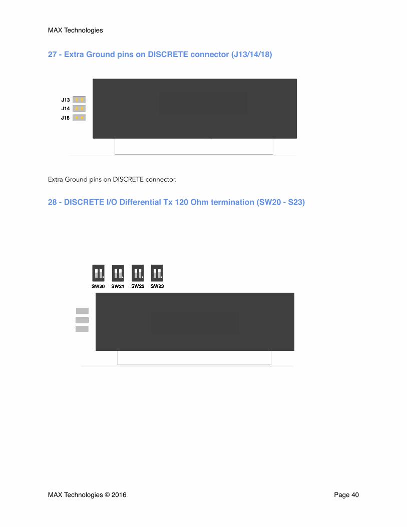
27 - Extra Ground pins on DISCRETE connector (J13/14/18)
Extra Ground pins on DISCRETE connector.
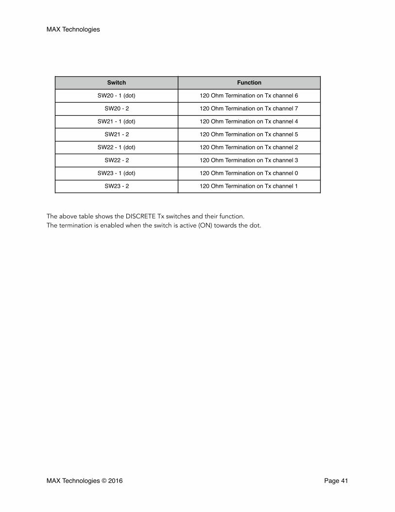
28 - DISCRETE I/O Differential Tx 120 Ohm termination (SW20 - S23)
MAX Technologies © 2016 Page �40
MAX Technologies
The above table shows the DISCRETE Tx switches and their function. The termination is enabled when the switch is active (ON) towards the dot.
Switch Function
SW20 - 1 (dot) 120 Ohm Termination on Tx channel 6
SW20 - 2 120 Ohm Termination on Tx channel 7
SW21 - 1 (dot) 120 Ohm Termination on Tx channel 4
SW21 - 2 120 Ohm Termination on Tx channel 5
SW22 - 1 (dot) 120 Ohm Termination on Tx channel 2
SW22 - 2 120 Ohm Termination on Tx channel 3
SW23 - 1 (dot) 120 Ohm Termination on Tx channel 0
SW23 - 2 120 Ohm Termination on Tx channel 1
MAX Technologies © 2016 Page �41
MAX Technologies
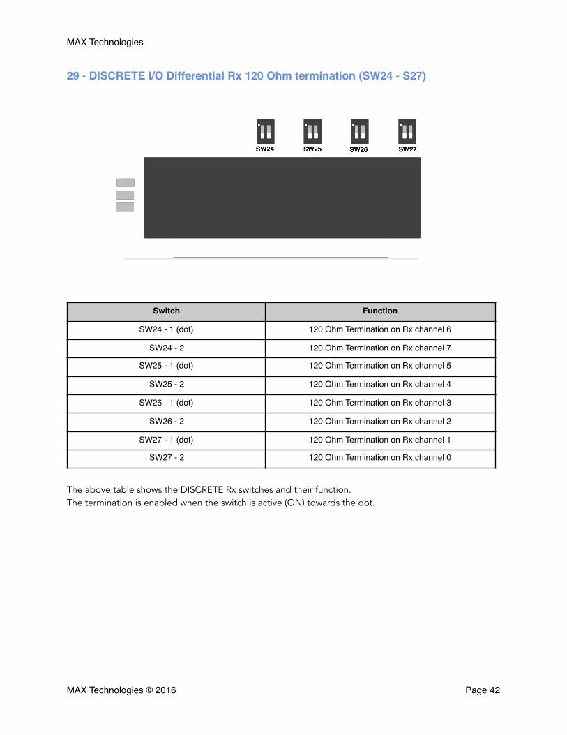
29 - DISCRETE I/O Differential Rx 120 Ohm termination (SW24 - S27)
The above table shows the DISCRETE Rx switches and their function. The termination is enabled when the switch is active (ON) towards the dot.
Switch Function
SW24 - 1 (dot) 120 Ohm Termination on Rx channel 6
SW24 - 2 120 Ohm Termination on Rx channel 7
SW25 - 1 (dot) 120 Ohm Termination on Rx channel 5
SW25 - 2 120 Ohm Termination on Rx channel 4
SW26 - 1 (dot) 120 Ohm Termination on Rx channel 3
SW26 - 2 120 Ohm Termination on Rx channel 2
SW27 - 1 (dot) 120 Ohm Termination on Rx channel 1
SW27 - 2 120 Ohm Termination on Rx channel 0
MAX Technologies © 2016 Page �42

MAX Technologies
30 - SYNC In / Sync Out Terminaison (SW28)
The above table shows the Sync In / Out switches and their function. The termination is enabled when the switch is active (ON) towards the dot.
Switch FunctionSW28 - 1 (dot) 120 Ohm Termination on Tx Sync Out
SW28 - 2 120 Ohm Termination on Rx Sync In
MAX Technologies © 2016 Page �43
MAX Technologies
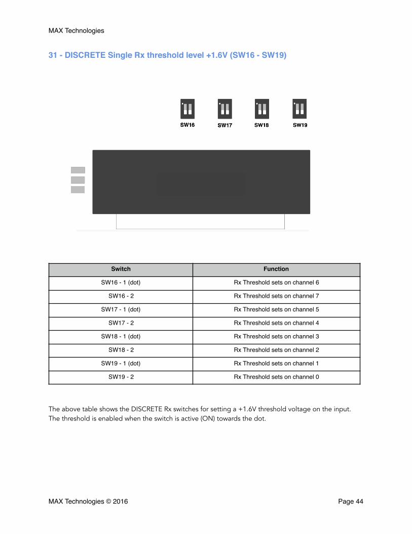
31 - DISCRETE Single Rx threshold level +1.6V (SW16 - SW19)
The above table shows the DISCRETE Rx switches for setting a +1.6V threshold voltage on the input. The threshold is enabled when the switch is active (ON) towards the dot.
Switch Function
SW16 - 1 (dot) Rx Threshold sets on channel 6
SW16 - 2 Rx Threshold sets on channel 7
SW17 - 1 (dot) Rx Threshold sets on channel 5
SW17 - 2 Rx Threshold sets on channel 4
SW18 - 1 (dot) Rx Threshold sets on channel 3
SW18 - 2 Rx Threshold sets on channel 2
SW19 - 1 (dot) Rx Threshold sets on channel 1
SW19 - 2 Rx Threshold sets on channel 0
MAX Technologies © 2016 Page �44
MAX Technologies
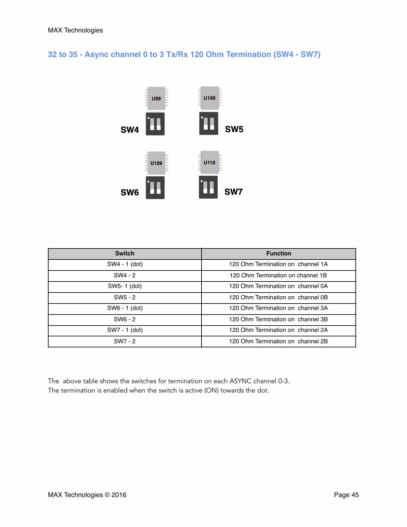
32 to 35 - Async channel 0 to 3 Tx/Rx 120 Ohm Termination (SW4 - SW7)
The above table shows the switches for termination on each ASYNC channel 0-3. The termination is enabled when the switch is active (ON) towards the dot.
Switch FunctionSW4 - 1 (dot) 120 Ohm Termination on channel 1A
SW4 - 2 120 Ohm Termination on channel 1BSW5- 1 (dot) 120 Ohm Termination on channel 0A
SW5 - 2 120 Ohm Termination on channel 0BSW6 - 1 (dot) 120 Ohm Termination on channel 3A
SW6 - 2 120 Ohm Termination on channel 3BSW7 - 1 (dot) 120 Ohm Termination on channel 2A
SW7 - 2 120 Ohm Termination on channel 2B
MAX Technologies © 2016 Page �45
MAX Technologies
Appendix A
Communicate with FlexMulti using Ethernet
The FlexMulti device gives you a variety of options to connect to a host computer. The default connec-tion that comes with every device is Ethernet. On the front of the device, you will find a standard RJ45 port. This is a 10/100/1000 Mbps port that has plenty of bandwidth for most applications. To connect, simply use a standard Ethernet cable and connect it to the FlexMulti port as well as your computer or network switch. Ethernet is convenient because of its low cost standard cables and connections as well as great throughput rates. It also allows multiple client applications to connect to the box remotely across the client’s existing IP network.
When connecting the FlexMulti through a network switch, you can use either static or dynamic IP ad-dressing. A static address is assigned by the user or network administrator and does not change. A Dy-namic address is assigned by a DHCP server on the client network.
There are two sets of DIP switches on the back of the device. These are used to control the network be-havior. On the second set of switches you will see a switch to specify local or remote connection as well activating DHCP.
If the DHCP switch is turned on, the FlexMulti will send out a DHCP request for a dynamic address.
If the DHCP is turned off, then the device will default to static addressing. The default static address subnet is 192.168.0.X, where X is the node identifier of the device. This number is set with the first set of DIP switches. The left most switch is the least significant bit. Use the switches to set the binary represen-tation of the node ID.
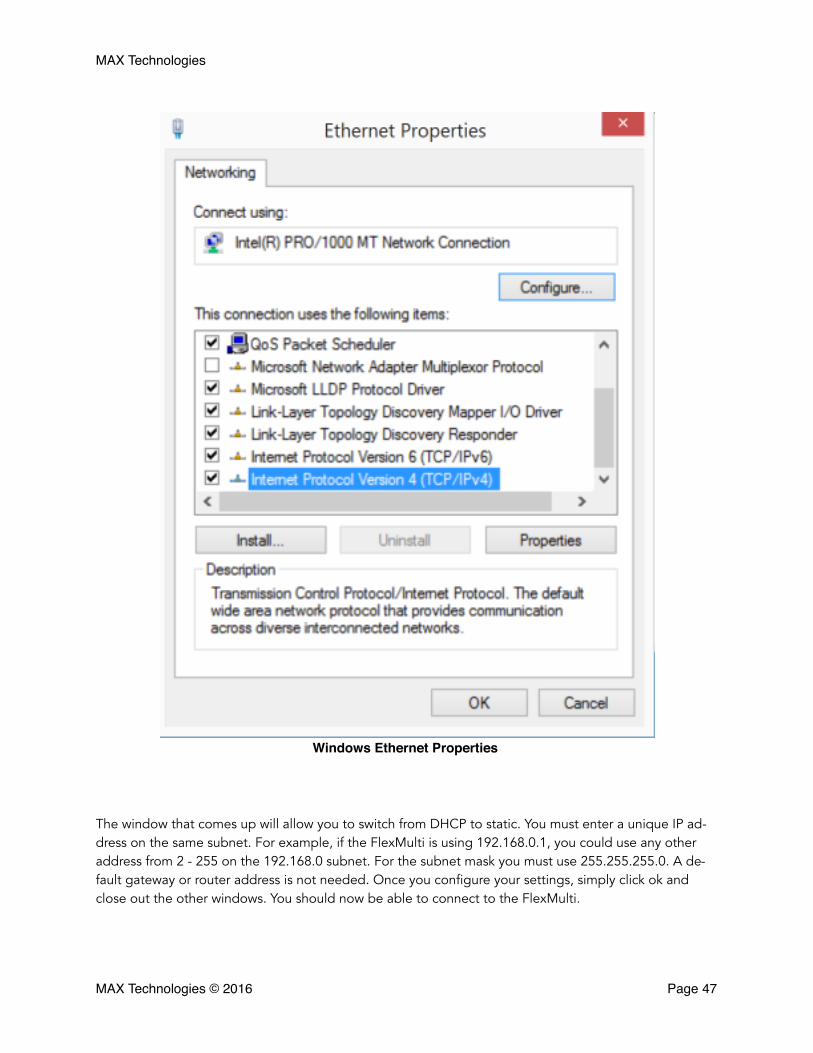
When connecting the device directly to a computer without going through a network switch it is essen-tial to use static addressing. In order to communicate, your computer will need to be configured with an address that is on the same subnet as the FlexMulti. In Windows this is accomplished using the Network tools under Control Panel. Right click on the adapter that is connected to the device and then click Properties. From here double-click on TCP/IP.
MAX Technologies © 2016 Page �46
MAX Technologies
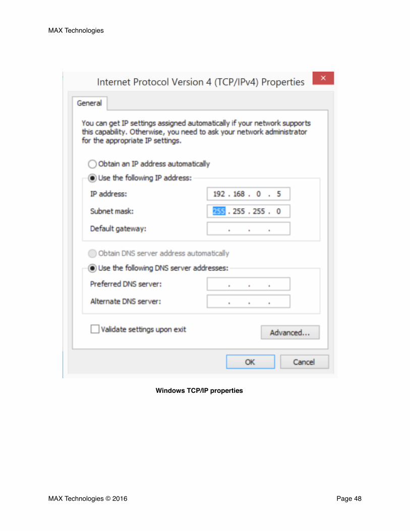
The window that comes up will allow you to switch from DHCP to static. You must enter a unique IP ad-dress on the same subnet. For example, if the FlexMulti is using 192.168.0.1, you could use any other address from 2 - 255 on the 192.168.0 subnet. For the subnet mask you must use 255.255.255.0. A de-fault gateway or router address is not needed. Once you configure your settings, simply click ok and close out the other windows. You should now be able to connect to the FlexMulti.
MAX Technologies © 2016 Page �47
Windows Ethernet Properties
MAX Technologies
MAX Technologies © 2016 Page �48
Windows TCP/IP properties

MAX Technologies
When using a Mac to connect to the device, first click on the apple on the system bar and then click Sys-tem Preferences. Then select Network. This will show you a list of all network adapters in your Mac. Se-lect the one that is being used and configure the IP address and subnet mask as directed above. You will have to change the setting to Manually unless already selected. You should now be able to connect to the FlexMulti With your Mac.
MAX Technologies © 2016 Page �49
OSX Network properties
MAX Technologies
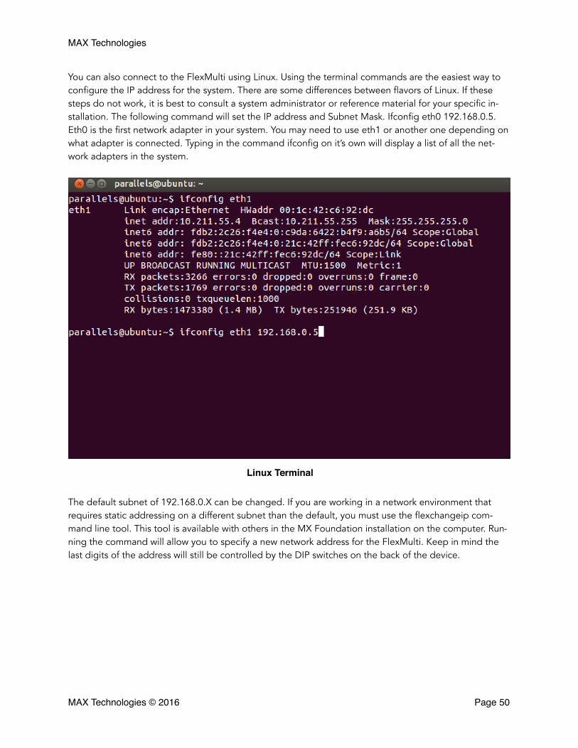
You can also connect to the FlexMulti using Linux. Using the terminal commands are the easiest way to configure the IP address for the system. There are some differences between flavors of Linux. If these steps do not work, it is best to consult a system administrator or reference material for your specific in-stallation. The following command will set the IP address and Subnet Mask. Ifconfig eth0 192.168.0.5. Eth0 is the first network adapter in your system. You may need to use eth1 or another one depending on what adapter is connected. Typing in the command ifconfig on it’s own will display a list of all the net-work adapters in the system.
The default subnet of 192.168.0.X can be changed. If you are working in a network environment that requires static addressing on a different subnet than the default, you must use the flexchangeip com-mand line tool. This tool is available with others in the MX Foundation installation on the computer. Run-ning the command will allow you to specify a new network address for the FlexMulti. Keep in mind the last digits of the address will still be controlled by the DIP switches on the back of the device.
MAX Technologies © 2016 Page �50
Linux Terminal