Flexible highly-effective energy harvester via crystallo ...fand.kaist.ac.kr/Attach/Nano Res -...
19
Flexible highly-effective energy harvester via crystallo- graphic and computational control of nanointerfacial morphotropic piezoelectric thin film Chang Kyu Jeong 1,2,†,§ , Sung Beom Cho 3,§ , Jae Hyun Han 1 , Dae Yong Park 1 , Suyoung Yang 4 , Kwi-Il Park 5 , Jungho Ryu 6 , Hoon Sohn 4 ( ), Yong-Chae Chung 3 ( ), and Keon Jae Lee 1 ( ) 1 Department of Materials Science and Engineering, Korea Advanced Institute of Science and Technology (KAIST), 291 Daehak-ro, Yuseong-gu, Daejeon 34141, Republic of Korea 2 KAIST Institute for the NanoCentury (KINC), 291 Daehak-ro, Yuseong-gu, Daejeon 34141, Republic of Korea 3 Division of Materials Science and Engineering, Hanyang University, 222 Wangsimni-ro, Seongdong-gu, Seoul 04763, Republic of Korea 4 Department of Civil and Environmental Engineering, KAIST, 291 Daehak-ro, Yuseong-gu, Daejeon 34141, Republic of Korea 5 Department of Energy Engineering, Gyeongnam National University of Science and Technology, 33 Dongjin-ro, Jinju, Gyeongnam 52725, Republic of Korea 6 Functional Ceramic Group, Korea Institute of Materials Science (KIMS), 797 Changwon-daero, Seongsan-gu, Changwon, Gyeongnam 51508, Republic of Korea † Present address: Department of Materials Science and Engineering, Materials Research Institute, The Pennsylvania State University, University Park, PA 16802, USA § These authors contributed equally to this work. Received: 1 August 2016 Revised: 20 September 2016 Accepted: 26 September 2016 © Tsinghua University Press and Springer-Verlag Berlin Heidelberg 2016 KEYWORDS energy harvesting, morphotropic phase boundary (MPB), piezoelectric, first-principles calculation, lead zirconium titanate (PZT) ABSTRACT Controlling the properties of piezoelectric thin films is a key aspect for designing highly efficient flexible electromechanical devices. In this study, the crystallographic phenomena of PbZr 1–x Ti x O 3 (PZT) thin films caused by distinguished interfacial effects are deeply investigated by overlooking views, including not only an experimental demonstration but also ab initio modeling. The polymorphic phase balance and crystallinity, as well as the crystal orientation of PZT thin films at the morphotropic phase boundary (MPB), can be stably modulated using interfacial crystal structures. Here, interactions with MgO stabilize the PZT crystallographic system well and induce the texturing influences, while the PZT film remains quasi-stable on a conventional Al 2 O 3 wafer. On the basis of this fundamental understanding, a high-output flexible energy harvester is developed using the controlled-PZT system, which shows significantly higher performance than the unmodified PZT generator. The voltage, current, and power densities are improved by 556%, 503%, and 822%, respectively, in comparison with the previous flexional single-crystalline piezoelectric device. Finally, the improved flexible generator is applied to harvest tiny vibrational energy from a real traffic system, and it is used to operate a commercial electronic unit. These results clearly indicate that atomic-scale designs can produce significant impacts on macroscopic applications. Nano Research 2017, 10(2): 437–455 DOI 10.1007/s12274-016-1304-6 Address correspondence to Hoon Sohn, [email protected]; Yong-Chae Chung, [email protected]; Keon Jae Lee, [email protected]
Transcript of Flexible highly-effective energy harvester via crystallo ...fand.kaist.ac.kr/Attach/Nano Res -...

Flexible highly-effective energy harvester via crystallo-graphic and computational control of nanointerfacialmorphotropic piezoelectric thin film
Chang Kyu Jeong1,2,†,§, Sung Beom Cho3,§, Jae Hyun Han1, Dae Yong Park1, Suyoung Yang4, Kwi-Il Park5,
Jungho Ryu6, Hoon Sohn4 (), Yong-Chae Chung3 (), and Keon Jae Lee1 ()
1 Department of Materials Science and Engineering, Korea Advanced Institute of Science and Technology (KAIST), 291 Daehak-ro,
Yuseong-gu, Daejeon 34141, Republic of Korea 2 KAIST Institute for the NanoCentury (KINC), 291 Daehak-ro, Yuseong-gu, Daejeon 34141, Republic of Korea 3 Division of Materials Science and Engineering, Hanyang University, 222 Wangsimni-ro, Seongdong-gu, Seoul 04763, Republic of Korea 4 Department of Civil and Environmental Engineering, KAIST, 291 Daehak-ro, Yuseong-gu, Daejeon 34141, Republic of Korea 5 Department of Energy Engineering, Gyeongnam National University of Science and Technology, 33 Dongjin-ro, Jinju, Gyeongnam
52725, Republic of Korea 6 Functional Ceramic Group, Korea Institute of Materials Science (KIMS), 797 Changwon-daero, Seongsan-gu, Changwon, Gyeongnam
51508, Republic of Korea † Present address: Department of Materials Science and Engineering, Materials Research Institute, The Pennsylvania State University,
University Park, PA 16802, USA § These authors contributed equally to this work.
Received: 1 August 2016
Revised: 20 September 2016
Accepted: 26 September 2016
© Tsinghua University Press
and Springer-Verlag Berlin
Heidelberg 2016
KEYWORDS
energy harvesting,
morphotropic phase
boundary (MPB),
piezoelectric,
first-principles calculation,
lead zirconium titanate
(PZT)
ABSTRACT
Controlling the properties of piezoelectric thin films is a key aspect for designing
highly efficient flexible electromechanical devices. In this study, the crystallographic
phenomena of PbZr1–xTixO3 (PZT) thin films caused by distinguished interfacial
effects are deeply investigated by overlooking views, including not only an
experimental demonstration but also ab initio modeling. The polymorphic phase
balance and crystallinity, as well as the crystal orientation of PZT thin films at the
morphotropic phase boundary (MPB), can be stably modulated using interfacial
crystal structures. Here, interactions with MgO stabilize the PZT crystallographic
system well and induce the texturing influences, while the PZT film remains
quasi-stable on a conventional Al2O3 wafer. On the basis of this fundamental
understanding, a high-output flexible energy harvester is developed using the
controlled-PZT system, which shows significantly higher performance than the
unmodified PZT generator. The voltage, current, and power densities are improved
by 556%, 503%, and 822%, respectively, in comparison with the previous flexional
single-crystalline piezoelectric device. Finally, the improved flexible generator is
applied to harvest tiny vibrational energy from a real traffic system, and it is
used to operate a commercial electronic unit. These results clearly indicate that
atomic-scale designs can produce significant impacts on macroscopic applications.
Nano Research 2017, 10(2): 437–455
DOI 10.1007/s12274-016-1304-6
Address correspondence to Hoon Sohn, [email protected]; Yong-Chae Chung, [email protected]; Keon Jae Lee, [email protected]

| www.editorialmanager.com/nare/default.asp
438 Nano Res. 2017, 10(2): 437–455
1 Introduction
Piezoelectric energy harvesting technology, which uses
abundant mechanical energy to generate electricity,
has been of prime interest in the field of self-powered
electronics to avoid frequent battery recharging [1–4].
In particular, flexible piezoelectric generators are
regarded as powerful candidates to harness tiny
movements (e.g., traffic vibrations) and conform to
curvilinear/corrugated surfaces (e.g., biological organs)
[5, 6]. For these reasons, many researchers have put
in significant efforts to develop flexible piezoelectric
energy harvesters using ZnO nanostructures, poly-
vinylidene fluoride (PVDF) membranes, or PbZr1–xTixO3
(PZT) films [1, 6–8]; however, thus far, their per-
formances have been insufficient to drive practical
applications such as Internet of Things (IoT) sensors
and wireless communications.
Recently, to overcome weak piezoelectricity, diverse
types of single-crystalline piezoceramic films with com-
plicated stoichiometry have been applied to flexible
harvesters for scavenging high-output energy [9–11].
However, such single crystalline films have critical
problems with severe piezoelectric degradation related
to domain size versus thickness, along with the
detrimental effect of grinding [11–14]. Moreover, it is
difficult to fabricate single crystals with thicknesses
below ~10 μm, which limits both mechanical flexibility
and vibrational responsivity [9]. Owing to their
limitations and high cost [15], flexible single-crystalline
systems are highly restricted to a narrow range of
applications; therefore, the systems inevitably require
new approaches to be established using microstructural-
controlled polycrystalline piezoelectric systems.
Piezoelectric properties of polycrystalline materials
are strongly dependent on crystal orientation, phase,
and crystallinity [16–18]. These crystallographic variables
play very crucial roles in boosting piezoelectricity
efficiently because well-controlled polycrystalline films
can exhibit excellent piezoresponses compared with
single crystalline structures [15]. Although several
basic studies have been reported in which the crystal
orientation of widely used PZT films has been
modified [18, 19], there is a considerable lack of
systematic material studies regarding piezoelectric
phase configuration and crystallinity. In particular, the
morphotropic phase boundary (MPB, i.e., multiphase
composition) in PZT thin films is almost unexplored
owing to their unclear phasic behaviors and interfacial
influences. In addition, most previous texturing controls
have utilized complex thermo/atmo-kinetics [20, 21],
intricate stress stimuli [22], or seed/buffer layers
[23–25], which are irreproducible and unsuitable
for device fabrication. These limitations in the crys-
tallographic prediction for PZT films need to be resolved
to achieve high-performance flexible piezoelectric
energy harvesters based on systemically well-designed
polycrystalline PZT films.
To modify the crystalline specifications of PZT and
enhance the efficiency of a flexible energy harvester,
we theoretically and experimentally investigated the
crystallographic control of piezoelectric PZT thin films
using substrate modulation. By introducing the first-
principles calculation as well as energy formalism to
investigate PZT interfacial nature, MPB-phasic deviation,
the variance of orientation, and crystallinity in the PZT
thin films were quantitatively examined, with lattice-
scale energy states of nucleation effects and orbital
hybridizations. This sophisticated ab initio modeling
can be used to guide the methodology for improving
piezoelectric energy devices, enabled by the com-
putational interpretation of PZT crystallographic
phenomena. On the basis of this quantum-mechanic
simulation, we demonstrated that the performance of
a crystallographic-controlled flexible PZT generator is
eight times higher than that of a single-crystalline film
generator. A flexible energy harvester was successfully
fabricated and applied to the energy conversion of
tiny vibrational modes, programmed by the real traffic
system of an expressway bridge.
2 Experimental
2.1 Fabrication processes of PZT thin films and
flexible energy harvesters
PZT is regarded as the best piezoelectric material
because of its excellent dielectric and ferroelectric pro-
perties and its facile and cheap fabrication method. We
used a sol–gel process to form PZT thin films owing to
the innumerable advantages, including excellent com-
position control and uniform homogeneity for MPB,

www.theNanoResearch.com∣www.Springer.com/journal/12274 | Nano Research
439 Nano Res. 2017, 10(2): 437–455
as well as simple fabrication and low temperature for
cost effectiveness [26]. Furthermore, it can also be
easily applied to crystallographic texturing because
the polymeric metal alkoxide species in the sol–gel
solution serve well as molecular building blocks for
crystallization, compared with vacuum deposition
methods [18, 27]. In this study, PZT thin films were
deposited on two different substrates by normal
methoxyethanol-based sol–gel solution processes.
The PZT thin films were prepared using a con-
ventional sol–gel solution process on double-side
polished MgO wafers (500-μm-thick, (100) surface
plane, American Elements Co.) and sapphire (Al2O3)
wafer (430-μm-thick, c-plane (0001) surface orientation,
Hi-Solar Co.). The concentration of the PZT sol–gel
solution (MEMS Solution Co.) is about 0.4 M, and the
Zr/Ti molar ratio is 52/48, which is the MPB com-
position. After solution spin casting on the wafers,
pyrolysis was implemented in air environment at
450 °C to eliminate polymeric constituents from the
as-deposited film. The deposition and pyrolysis
processes were repeated several times to achieve a
2-μm-thick PZT thin film, followed by crystallization
in O2-rich atmosphere at 650 °C. The PZT thin films
on both wafers were firmly attached to polyethylene
terephthalate (PET) substrates (125-μm-thick, Sigma-
Aldrich) using an ultraviolet (UV) light-curable
polyurethane acrylate (PUA)-based resin (Norland
optical adhesive, Norland Products Inc.). After UV
light exposure to the samples through the clear PET
side, a two-dimensional (2D)-pulsed XeCl excimer
laser (λ = 308 nm, square-shaped area of 625 μm ×
625 μm) was utilized to irradiate the backside of the
wafers for separating the flexible PET-attached PZT
thin film from the rigid wafers. For the laser lift-off
(LLO) process, the 308 nm-wavelength laser (duration
time ~30 ns) penetrates each wafer from the backside
because the laser photonic energy (4.02 eV) is signifi-
cantly lower than the substrate band gap energy levels
(7–10 eV). Consequently, the PZT thin film completely
absorbs the laser energy at the substrate interface,
followed by partial melting and dissociation of PZT
owing to the lower band gap energy of PZT (3.2–
3.6 eV) than the photonic energy of XeCl laser. The
optimum optical power levels of the laser beam were
~31 and ~20 mW in the cases of PZT/MgO wafer and
PZT/sapphire wafer, respectively. The power and
energy density of the laser beam was detected using
a photodetector (Coherent Co.). We use the (100) MgO
wafer not only because of the crystalline coherency
with PZT but also the common utilization in optics.
Moreover, (0001) Al2O3 (c-plane) is widely used in the
commercial LLO fabrication. We also obtained the
X-ray diffraction (XRD) peaks of PZT thin films on
the rest of the Al2O3 wafers with other surface planes
(m-plane and a-plane), which also showed random
orientation of PZT films (Fig. S1 in the Electronic
Supplementary Material (ESM)). Furthermore, no
other planes of Al2O3 with the exception of c-plane
are reliable as first-principles calculation with DFT
computation because only the c-plane has the database
in the Vienna ab initio quantum mechanics package,
as described in Section 2.2.
Interdigitated electrodes (IDEs) with a finger length
of 1.3 cm, electrode width of 100 μm, inter-electrode
gap of 100 μm, and 33 digitate pairs were fabricated
on the flexible PZT thin film by Ti and Au sputtering
(110-nm-thick) and standard photolithography. To
protect the surface of PZT and electrodes from
mechanical damage and electrical shock, the energy
harvesters were coated with SU-8 photoresist (5-μm-
thick, MicroChem) with metal contact holes pattern-
ing for wiring. Poling processes to make remnant
polarization of the PZT thin films were performed
using electric fields of about 90 kV·cm−1 overnight.
2.2 First-principles computational calculation of
PZT thin-film systems
First-principles calculations were carried out by solving
the Kohn–Sham equation with a plane-wave basis set,
as implemented in Vienna ab initio simulation package
(VASP) code [28]. The basis set of plane waves was
expanded to a cut off energy of 400 eV. The projector-
augmented wave (PAW) method was used to describe
the interactions between the valence electrons and the
atomic core [29]. For PAW calculations, the 5d106s26p2,
3d24s1, and 4d25s1 electrons were treated as valence
electrons for Pb, Ti, and Zr atoms, respectively. For
Mg and Al, 2s2p orbitals were considered as core
electrons, whereas only the 1s orbital was treated as
a core electron in oxygen. The exchange correlation
function was described with the Perdew–Burcke–

| www.editorialmanager.com/nare/default.asp
440 Nano Res. 2017, 10(2): 437–455
Ernzerhof form of the generalized gradient appro-
ximation [30].
We constructed the supercell model to investigate
the substrate effect of MgO and Al2O3 on PZT. The
MgO substrate was described as six layers of (001)
slabs where the bottom three layers of the substrates
were fixed to the lattice parameters of the bulk. On
the constructed substrate, eight layers of PZT were
deposited with rhombohedral and tetragonal phases.
Similarly, the PZT on Al2O3 supercell consists of six
layers of (0001) slabs of Al2O3 and eight layers of PZT.
The bottom three layers of Al2O3 were kept fixed to
the parameter of bulk Al2O3. A vacuum layer of at
least 15 Å was introduced to eliminate the interaction
between supercells. A Brillouin-zone integration for
the supercells was made with the grids of Monkhorst–
Pack 3 × 3 × 1 and 3 × 4 × 1 for PZT//MgO and
PZT//Al2O3, respectively [31]. Owing to the inevitable
differences of lattice symmetry between MgO (cubic)
and Al2O3 (hexagonal scalenohedron), the Monkhorst–
Pack grid sampling of PZT//Al2O3 should be slightly
high to satisfy the accurate density of states (DOS) as
well as the total energy order. All constituent atoms
were fully relaxed until the maximum total Hellmann–
Feynman forces were in the range of 0.01 eV·Å−1.
For the interpretation of the stability of the interface,
the interface energy Eγ was evaluated by
bulk bulk
tot PZT PZT sub sub PZT sub
1– – – –E E N E N E
A (1)
where Etot is the total energy of the entire system, bulk
PZTE and bulk
subE are the energies of the bulk state of
PZT and substrates, respectively, and A is the area of
each cell [32, 33]. The σPZT and σsub are the free surface
energies of PZT and substrates, respectively. After
subtracting the entire bulk energy and free surface
energy terms from the total system energy, only the
interfacial energy Eγ remains. The surface energy of
each cell was calculated from a symmetric slab model,
and all energy terms were calculated by the defined
first-principles calculation.
2.3 Measurement of output signals
A variety of XRD data (θ–2θ, 2θ, ω, and finely
narrow scans) were performed by Ultima IV (Rigaku),
SmartLab (Rigaku), D/MAX-2500 (Rigaku), and
X’Pert-PRO MRD (PANalytical). The field-dependent
piezoelectric coefficients are measured using a thin
film analyzer (TF 1000, aixACCT Systems) with laser
interferometry, a voltage amplifier, and an optical
table. Optional oscilloscopes could also be applied to
the measurement. In order to evaluate d33 values, we
used sandwich-type samples composed of indium tin
oxide (ITO, bottom electrode)/PZT/Pt (top electrode)
with an active area of 0.5 cm2. The bottom electrode
on PET should be selected as a UV-transparent
conductor because the PZT film should be attached
on the PET by the UV-curable resin before LLO
transfer (see Section 2.1, note that the Norland resin
must be cured by UV penetrating through the PET).
In addition, it should be noted that the laser
interferometry-based film method is hardly applied
directly to IDE-type devices. The flexible PZT thin-
film energy harvesters were iteratively bent by a linear
motor to measure the produced electrical signals. The
applied strain to PZT thin film was calculated to be
0.3% by the mechanical equations. The voltage and
current output were measured using a measuring
device (2612A SourceMeter System, Keithley) and a
low-noise current preamplifier (Model SR570, Stanford
Research Systems). All measurement processes were
conducted in a Faraday cage on an optical table
(vibration isolation system) to leave out extraneous
stimuli. To simulate electric signals of the energy
harvesters in traffic systems, we used a function
generator/mechanical vibrator system (Pasco Scientific
Co.) and a waveform generator (33220A, Agilent Co.)
that can read external programming motions. The
input data of traffic vibrations were programmed by
motion sensors at the 180-m-long Yeondae Bridge
(distance between piers: ~45 m, width between crash
walls: ~12.6 m) of Jungbunaeryuk (Central Inland)
Expressway through Yeoju City (Republic of Korea).
The average speed of vehicles was approximately
100 km·h−1.
3 Results and discussion
3.1 Design and concept for crystallographic control
of PZT thin film
Figure 1(a) shows the crystallographic-controlled
piezoelectricity depending on MgO and sapphire

www.theNanoResearch.com∣www.Springer.com/journal/12274 | Nano Research
441 Nano Res. 2017, 10(2): 437–455
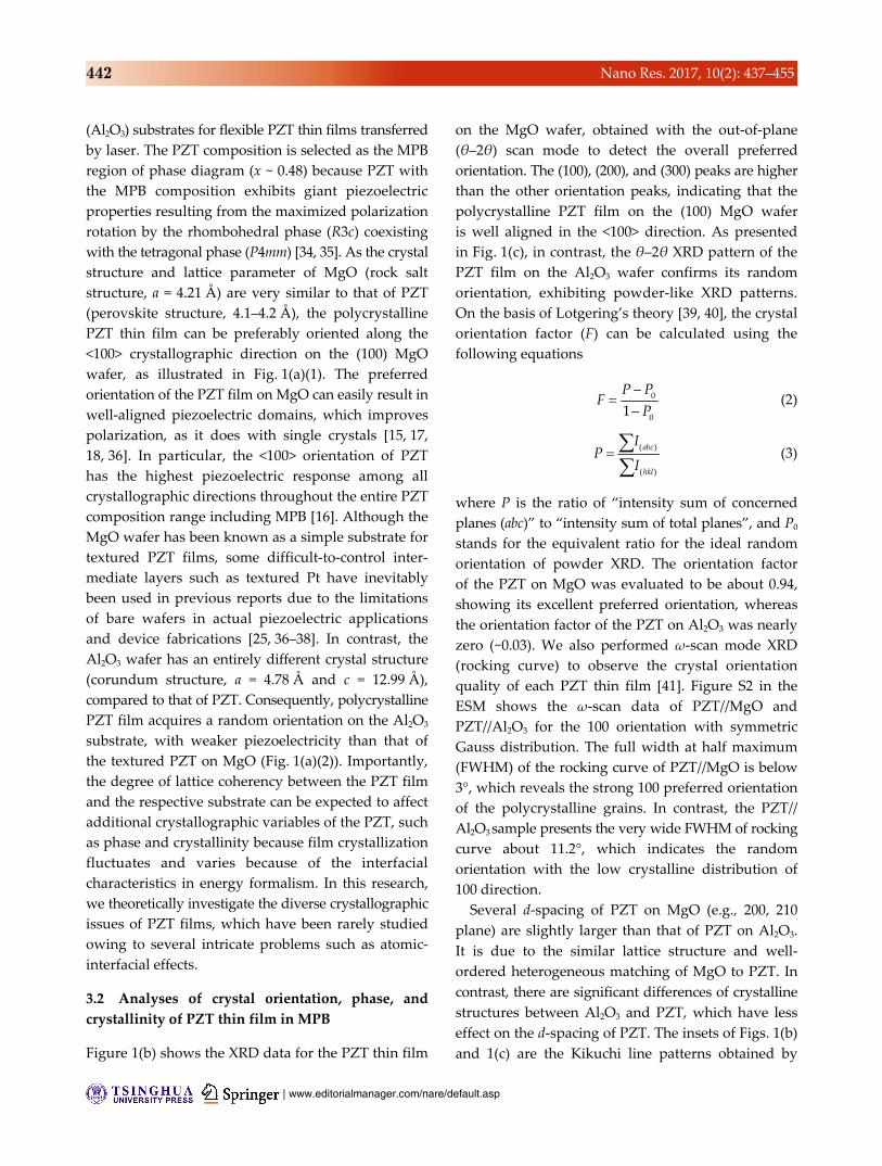
Figure 1 Conception and characterizations of crystallographic control of the PZT thin films in MPB. (a) Illustrations of the conceptfor crystallographic control over PZT thin films by simple wafer selection: (1) MgO and (2) sapphire wafer. The PZT thin films can beeasily transferred onto flexible substrates by wafer-penetrating laser, i.e., laser lift-off. The arrows in the PZT thin films denotepiezoelectric dipoles. For the sake of simplicity and unity, the commercial word “sapphire” is replaced by “Al2O3”. (b) and (c) XRDpatterns with θ–2θ scan mode of PZT thin films on (100) MgO and (0001) Al2O3 wafers. The asterisks denote the peaks from thebottom substrates, MgO and Al2O3. Insets: Kikuchi lines captured by EBSD of each PZT films. (d) and (e) Raman spectra of PZT filmson the MgO and Al2O3 wafers. The asterisks denote the specific peaks from the Al2O3 wafer. Insets: cross-sectional SEM images ofeach PZT thin films. The inset indicates that the 2 μm-thick PZT thin films are equally deposited on both substrates by the same sol–gelmethod. (f) and (g) HRTEM images of PZT films on the MgO and Al2O3 wafers showing exact lattice configurations at their interfaces.The top and bottom insets display SAED patterns of wafer substrates and each PZT film, respectively. The slight tilt and expansion ofPZT lattice on MgO is presumably caused by rhombohedral contents and interfacial lattice matching, respectively. The SAED patternsof PZT film on the Al2O3 wafer are vague and irregular, similar to a semi-amorphous crystalline film (the top inset of (g)), compared tothe definite and uniform patterns of PZT on the MgO (the top inset of (f)).
| www.editorialmanager.com/nare/default.asp
442 Nano Res. 2017, 10(2): 437–455
(Al2O3) substrates for flexible PZT thin films transferred
by laser. The PZT composition is selected as the MPB
region of phase diagram (x ~ 0.48) because PZT with
the MPB composition exhibits giant piezoelectric
properties resulting from the maximized polarization
rotation by the rhombohedral phase (R3c) coexisting
with the tetragonal phase (P4mm) [34, 35]. As the crystal
structure and lattice parameter of MgO (rock salt
structure, a = 4.21 Å) are very similar to that of PZT
(perovskite structure, 4.1–4.2 Å), the polycrystalline
PZT thin film can be preferably oriented along the
<100> crystallographic direction on the (100) MgO
wafer, as illustrated in Fig. 1(a)(1). The preferred
orientation of the PZT film on MgO can easily result in
well-aligned piezoelectric domains, which improves
polarization, as it does with single crystals [15, 17,
18, 36]. In particular, the <100> orientation of PZT
has the highest piezoelectric response among all
crystallographic directions throughout the entire PZT
composition range including MPB [16]. Although the
MgO wafer has been known as a simple substrate for
textured PZT films, some difficult-to-control inter-
mediate layers such as textured Pt have inevitably
been used in previous reports due to the limitations
of bare wafers in actual piezoelectric applications
and device fabrications [25, 36–38]. In contrast, the
Al2O3 wafer has an entirely different crystal structure
(corundum structure, a = 4.78 Å and c = 12.99 Å),
compared to that of PZT. Consequently, polycrystalline
PZT film acquires a random orientation on the Al2O3
substrate, with weaker piezoelectricity than that of
the textured PZT on MgO (Fig. 1(a)(2)). Importantly,
the degree of lattice coherency between the PZT film
and the respective substrate can be expected to affect
additional crystallographic variables of the PZT, such
as phase and crystallinity because film crystallization
fluctuates and varies because of the interfacial
characteristics in energy formalism. In this research,
we theoretically investigate the diverse crystallographic
issues of PZT films, which have been rarely studied
owing to several intricate problems such as atomic-
interfacial effects.
3.2 Analyses of crystal orientation, phase, and
crystallinity of PZT thin film in MPB
Figure 1(b) shows the XRD data for the PZT thin film
on the MgO wafer, obtained with the out-of-plane
(θ–2θ) scan mode to detect the overall preferred
orientation. The (100), (200), and (300) peaks are higher
than the other orientation peaks, indicating that the
polycrystalline PZT film on the (100) MgO wafer
is well aligned in the <100> direction. As presented
in Fig. 1(c), in contrast, the θ–2θ XRD pattern of the
PZT film on the Al2O3 wafer confirms its random
orientation, exhibiting powder-like XRD patterns.
On the basis of Lotgering’s theory [39, 40], the crystal
orientation factor (F) can be calculated using the
following equations
0
0
–
1
P PF
P
(2)
( )
( )
abc
hkl
IP
I
(3)
where P is the ratio of “intensity sum of concerned
planes (abc)” to “intensity sum of total planes”, and P0
stands for the equivalent ratio for the ideal random
orientation of powder XRD. The orientation factor
of the PZT on MgO was evaluated to be about 0.94,
showing its excellent preferred orientation, whereas
the orientation factor of the PZT on Al2O3 was nearly
zero (~0.03). We also performed ω-scan mode XRD
(rocking curve) to observe the crystal orientation
quality of each PZT thin film [41]. Figure S2 in the
ESM shows the ω-scan data of PZT//MgO and
PZT//Al2O3 for the 100 orientation with symmetric
Gauss distribution. The full width at half maximum
(FWHM) of the rocking curve of PZT//MgO is below
3°, which reveals the strong 100 preferred orientation
of the polycrystalline grains. In contrast, the PZT//
Al2O3 sample presents the very wide FWHM of rocking
curve about 11.2°, which indicates the random
orientation with the low crystalline distribution of
100 direction.
Several d-spacing of PZT on MgO (e.g., 200, 210
plane) are slightly larger than that of PZT on Al2O3.
It is due to the similar lattice structure and well-
ordered heterogeneous matching of MgO to PZT. In
contrast, there are significant differences of crystalline
structures between Al2O3 and PZT, which have less
effect on the d-spacing of PZT. The insets of Figs. 1(b)
and 1(c) are the Kikuchi line patterns obtained by

www.theNanoResearch.com∣www.Springer.com/journal/12274 | Nano Research
443 Nano Res. 2017, 10(2): 437–455
electron backscatter diffraction (EBSD) to compare
the two PZT films. The Kikuchi lines of the PZT on
the MgO also display a uniformly defined stereographic
map with strong [100], [110], and [111] reflector lines
induced by the texturing, whereas those on the Al2O3 show irregular and high-index patterns such as [2
_
54_
],
[3_
97_
], and [1_
43_
].
Raman spectroscopy was performed to investigate
the phases of the PZT thin films on the two different
substrates, as shown in Figs. 1(d) and 1(e). Phase issues
are critical factors in piezoelectric properties because
the PZT phases directly affect diverse polarization
routes. The continuous phase transition and coexistence
throughout the MPB region between rhombohedral
PZT (r-PZT) and tetragonal PZT (t-PZT) produce the
outstanding electromechanical characteristics [34, 42].
Intriguingly, the Raman spectra of each PZT thin film
describe different phase tendencies, even though the
MPB composition and the deposition condition were
completely identical. Figure 1(d) is the spectrum from
the PZT film on MgO, designating the coexistence of
r-PZT and t-PZT as the standard MPB region (Fig. 1(d))
[43]. On the other hand, Fig. 1(e) exhibits the Raman
shift of the PZT film on Al2O3 where the bands of the
A1(1LO)+E(2LO), E(2TO), and E+B1 modes abruptly
increase in intensity, showing that t-PZT is superior
to r-PZT [43]. In particular, the clear appearance
of the A1(2TO) mode is the unequivocal signature of
tetragonal-dominant MPB rather than rhombohedral
[44]. The collapsed phase balance into t-PZT is
maleficent to piezoelectricity in the MPB composition
of the PZT thin films on Al2O3. These phasic behaviors
of PZT films on MgO and Al2O3 are also supported
by the glancing (2θ) scan XRD data (Fig. S1 in the
ESM), corresponding to peak broadening or splitting.
This phase variation in the PZT thin film is not
caused by any stoichiometric composition changes,
as demonstrated by the energy-dispersive X-ray
spectroscopy (EDS) results, which indicate almost the
same composition and no chemical reaction in either
of the PZT films (Figs. S3 and S4, and Table S1 in the
ESM). To additionally investigate the MPB phase
balances of each PZT thin film, we performed and
analyzed high-resolution fine-scan XRD with {200}
peaks [45, 46]. In PZT//MgO, as shown in Fig. S5(a)
in the ESM, the rhombohedral phase component is
slightly dominant compared to the tetragonal element
according to deconvoluted portions. In contrast, the
tetragonal component is more predominant than the
rhombohedral in PZT//Al2O3 (Fig. S5(c) in the ESM),
similar to Raman spectroscopy.
As shown in the high-resolution transmission
electron microscopy (HRTEM) image of Fig. 1(f), the
preferred <100>-oriented PZT lattice is well matched
and stitched with the (100) plane of the MgO single-
crystalline substrate. The selected area electron
diffraction (SAED) patterns in the insets of Fig. 1(f)
display the high-lattice coherency between the MgO
wafer and the directional-grown PZT thin film. On
comparison, the HRTEM images and the SAED
patterns in Fig. 1(g) show the sharp flatness of the
Al2O3 surface and the random orientation of the
PZT crystallites, indicating that there is no crystalline
relationship between the Al2O3 wafer and the deposited
PZT film. Interestingly, these TEM and SAED analyses
confirm that the crystallinity of the PZT thin film on
MgO is also much better than that of PZT on Al2O3,
resulting in improved PZT piezoelectricity on the
MgO substrate. These propensities for crystalline
orientation and crystallinity are maintained up to
the top parts of each PZT film (Fig. S6 in the ESM).
The overall dark-field TEM and the high-resolution
backscattered electron (BSE) SEM are also explained
in Figs. S7 and S8 in the ESM.
3.3 First-principles calculation of PZT thin-film
system
We performed first-principles calculations with
density functional theory (DFT) for the PZT thin
films on each basal substrate, to not only systemically
explain the crystal orientation difference but also
fundamentally interpret the phase variation and
distinguished crystallinity. The first-principles calcula-
tions are based on the Kohn–Sham equation as con-
ducted in the VASP code [28]. The calculation steps
are described in our previous studies and in the
Experimental section in detail [29, 30, 47–50]. It should
be noted that the quantum mechanical calculations
for the PZT thin films with MPB composition were
applied to the rhombohedral and tetragonal phases,
since the thermodynamic restriction about the
monoclinic phase is not already severe in the energy
| www.editorialmanager.com/nare/default.asp
444 Nano Res. 2017, 10(2): 437–455
formalism such as order-invariant coefficients [35].
Furthermore, the controversy about monoclinic adaptive
states (ma-, mb-, and mc-PZT) can be reasonably negated
in the ab initio simulation because the monoclinic
symmetry (Cm or Pm) is regarded as the subgroup of
both rhombohedral and tetragonal symmetries at
nanotwins [42, 51].
The basic structure and formation of the PZT crystals
(i.e., r-PZT and t-PZT) were calculated to investigate
the PZT thin films on each substrate, as shown in
Fig. 2(a). The lattice parameters of r-PZT were calculated
to be a = 4.11 Å and α = 89.23° (Fig. 2(a)(1)), whereas
those of t-PZT were determined to be a = 4.01 Å and
c = 4.16 Å (Fig. 2(a)(2)). These geometric predictions
in conventional unit cell systems are almost consistent
with previously reported analytical experiments [52, 53].
As recorded in Fig. 2(a), the formation energy (Eform)
levels of r-PZT and t-PZT were then solved as −7.64
and −7.95 eV per primitive cell (Fig. S9 in the ESM),
respectively.
3.4 Interpretation for the control of crystal
orientation
To clarify the nature of the PZT thin films on the two
different substrates, the interfacial energy (Eγ) levels
between the films and substrates were evaluated.
As shown in Fig. 2(b), the first-principles modeling
identifies the [100] crystalline orientation of the PZT
thin films as the most stable configuration on the [100]
MgO wafer, in cases of both the coexisting r-PZT
and t-PZT. In the r-PZT system, the [100] texturing
direction is reasonable with a rhombohedral angle
α of nearly 90°, since the lattice parameter a is very
similar to that of MgO. In the coexisting t-PZT
(Fig. 2(b)(2)), the preferred orientation is not [001] but
[100], which means that the c-axis of the tetragonal
cell is parallel to the interface with the MgO wafer. It
is because the lattice parameter along c-axis (4.16 Å)
of t-PZT is closer to the lattice parameter of MgO
(4.20 Å) rather than a-axis (4.01 Å) of t-PZT. Thereby,
a smaller uniaxial strain is applied on the (100) plane
of t-PZT (a- × c-axes) on the (100) plane of MgO than
the (001) plane (a- × a-axes). Note that this coexisting
t-PZT configuration is advantageous to IDE-type
devices, arranged along the c-axis of t-PZT, owing to
the high polarization translation in c-axis. Consequently,
these crystal orientations of PZT with MPB on the MgO
substrate can produce large piezoelectric properties,
resulting from the maximized polarization rotation of
r-PZT and the maximum translation of t-PZT [34, 54].
On the [0001] Al2O3 wafer, in contrast, the calculated
Eγ of both the [100]-textured r-PZT and t-PZT films is
about ten times higher than that of the MgO wafer, as
compared in Figs. 2(b) and 2(c). Not only the [100]
orientation but also other higher-index orientations
of the PZT are energetically unfavorable on the Al2O3
substrate. Therefore, the PZT thin film inevitably forms
a random orientation on the Al2O3 wafers because
there is no matching orientation between the film and
the substrate. Even the Eγ of lowest index-textured
PZT on Al2O3 (0.142 and 0.154 eV·Å−2 converted as
~230 and ~250 kJ·mol−1) is much higher than the growth
activation energy of the PZT film (~110 kJ·mol−1)
calculated by the Avrami method [55].
3.5 Interpretation for the modulation of crystallinity
The degree of crystallinity can also be delineated by
the DFT results and the crystallization-free energy.
Because the Eγ between PZT and MgO is sufficiently
low (Fig. 2(b)), heterogeneous nucleation can occur
stably and easily at the crystallographic-coherent
interface during PZT crystallization. In the case of
PZT on Al2O3, however, the nucleation step cannot
happen ordinarily at the interface due to the high Eγ
between the PZT and Al2O3, as shown in Fig. 2(c).
Instead, heterogeneous nucleation can arise inter-
mittently at free surfaces, sol–gel polymeric inclusions,
or incoherent-interfacial clingers during the PZT
crystallization on Al2O3; however, the nucleation step
is rendered slow and sluggish because all of these
sites also have high energy levels, compared to the
Eγ of the PZT on MgO (e.g., the free surface energy
of PZT thin films 0.06–0.09 eV·Å−2). Therefore, it
is clear that the nucleation events strongly depend
upon the underlying interface. As nucleation is the
determining step of perovskite formation and the
critical step of crystallinity in the entire PZT crys-
tallization mechanism [55, 56], the crystallinity of PZT
on Al2O3 is poorer than that of PZT on MgO, in
accordance with the TEM analyses. The BSE-SEM

www.theNanoResearch.com∣www.Springer.com/journal/12274 | Nano Research
445 Nano Res. 2017, 10(2): 437–455
images can also imply the nucleation tendencies
(Fig. S8 in the ESM).
3.6 Interpretation for the modulation of MPB
phase balance
The DFT calculations sequentially explain the phase
variation of the PZT thin films according to the basal
substrates. On the MgO substrate, the Eγ levels of
r-PZT (Fig. 2(b)(1)) and t-PZT (Fig. 2(b)(2)) are almost
the same; the energy difference is just 0.0051 eV·Å−2
(~8 kJ·mol−1). Hence, the two phases of PZT can easily
and naturally coexist as a MPB composition on the
MgO wafer due to the slight energy difference.
Although there is a subtle energetic predominance of
r-PZT caused by the interfacial lattice strain difference,
it can be rather beneficial owing to the piezoelectric
priority of the <100>-textured rhombohedral phase,
as noted in the Raman spectroscopy analyses [16, 57].
Consequently, the well-balanced MPB phase state of
the PZT film on MgO induces a synergetic effect for
the dramatic increase of piezoelectricity, along with
the preferred orientation and excellent crystallinity.
In contrast to the PZT//MgO system, the PZT//Al2O3
system cannot utilize the calculated interfacial behaviors
with preferred orientation (Fig. 2(c)) to resolve the
phase variation phenomenon because of the confirmed
random orientation and non-interfacial nucleation. In
place of the interfacial variants, the inherent formation
(Eform) of each PZT phase becomes the main determinant
for the PZT phase states on the Al2O3 substrate. As
shown in Fig. 2(a), there is a considerable difference
in Eform between r-PZT and t-PZT, of 0.312 eV·cell−1
(~30 kJ·mol−1), causing a pseudo-balanced phase state
with energetic dominance of t-PZT, despite the MPB
composition.
3.7 Interfacial states and polarization
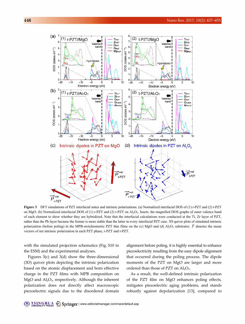
Figures 3(a) and 3(b) depict the DOS at PZT//MgO
and PZT//Al2O3 interfaces. The differences in Eγ of
the PZT films on each substrate are caused by the
lattice coherency between PZT and substrates. Since
the lattice structures and parameters of the MgO are
very analogous to those of the PZT crystals, the DOS
at the PZT//MgO interface indicates strong hybridized
bonds, as indicated by the aligned DOS ridges (inset of
Fig. 3(a)). In contrast, as shown in the misalignments
of DOS (inset of Fig. 3(b)), there is no hybridization at
the PZT//Al2O3 interface, because there are numerous
broken and instable dangling bonds. These first-
principles DFT calculations for DOS are consistent
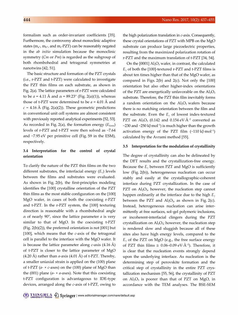
Figure 2 First-principles calculations of rhombohedral and tetragonal PZT thin films on MgO and Al2O3. (a) First-principles DFT-calculated conventional cell and formation energy of (1) r-PZT and (2) t-PZT. (b) Calculated crystal structures, bonds, minimized lattice strain, and interfacial energy of [100]-oriented (1) r-PZT and (2) t-PZT on a [100] direction MgO wafer. (c) Calculated crystal structures, bonds, minimized lattice strain, and interfacial energy of [100]-oriented (1) r-PZT and (2) t-PZT on a [0001] direction Al2O3 wafer. Each elemental atom is denoted in different colors: Pb—green, Zr—cyan, Ti—pink, O—gray, Mg—red, and Al—blue.
| www.editorialmanager.com/nare/default.asp
446 Nano Res. 2017, 10(2): 437–455
with the simulated projection schematics (Fig. S10 in
the ESM) and the experimental analyses.
Figures 3(c) and 3(d) show the three-dimensional
(3D) quiver plots depicting the intrinsic polarization
based on the atomic displacement and born effective
charge in the PZT films with MPB composition on
MgO and Al2O3, respectively. Although the inherent
polarization does not directly affect macroscopic
piezoelectric signals due to the disordered domain
alignment before poling, it is highly essential to enhance
piezoelectricity resulting from the easy dipole alignment
that occurred during the poling process. The dipole
moments of the PZT on MgO are larger and more
ordered than those of PZT on Al2O3.
As a result, the well-defined intrinsic polarization
of the PZT film on MgO enhances poling effects,
mitigates piezoelectric aging problems, and stands
robustly against depolarization [13], compared to
Figure 3 DFT simulations of PZT interfacial states and intrinsic polarizations. (a) Normalized interfacial DOS of (1) r-PZT and (2) t-PZTon MgO. (b) Normalized interfacial DOS of (1) r-PZT and (2) t-PZT on Al2O3. Insets: the magnified DOS graphs of outer valence band of each element to show whether they are hybridized. Note that the interfacial calculations were conducted at the Ti, Zr layer of PZT,rather than the Pb layer because the former is more stable than the latter in every interfacial PZT case. 3D quiver plots of simulated intrinsicpolarization (before poling) in the MPB-stoichiometric PZT thin films on the (c) MgO and (d) Al2O3 substrates.
P denotes the mean
vectors of net intrinsic polarization in each PZT phase, r-PZT and t-PZT.

www.theNanoResearch.com∣www.Springer.com/journal/12274 | Nano Research
447 Nano Res. 2017, 10(2): 437–455
the case of the Al2O3 substrate. The partial loss of
ferroelectric nature in the PZT film on Al2O3 is pre-
sumably due to the drastic distortions of the perovskite
structure caused by the interfacial instability.
3.8 Flexible crystallographic-controlled PZT thin
film
Figure 4(a) shows the flexible energy harvester using
the highly optimized PZT thin film based on thorough
theoretical atomic investigations. The crystallographic-
controlled PZT film prepared on MgO was successfully
transferred onto a flexible PET sheet without material
failure even during laser irradiation (i.e., inorganic-
based laser lift-off, ILLO), which is similar to the
conventional case of the non-controlled PZT film
on Al2O3 (Fig. 4(b)). In the ILLO process, a 308 nm-
wavelength XeCl pulsed laser (duration time ~30 ns)
penetrates each wafer from the backside since the
laser photonic energy (4.02 eV) is much smaller
than the substrate band gap energy levels (7–10 eV).
Figure 4 PZT thin-film energy harvesters from (a) the MgO wafer and (b) the Al2O3 wafer. Insets: as-transferred PZT thin films on PET substrates using the ILLO processes. Cross-sectional high-resolution SEM images of FIB-cut flexible PZT films from (c) the MgO wafer and (d) the Al2O3 wafer. Some pores of the PZT thin films shown in the SEM images are induced by the ion-cutting damage. (e) and (f) θ–2θ scan and 2θ scan (insets) XRD of PZT thin films from the MgO and the Al2O3, respectively. (g) and (h) Raman spectraof each PZT thin film from the MgO wafer and the Al2O3 wafer. Some peaks from the PET substrates are marked as asterisks. Insets:optical microscopy images of each PZT film surface from MgO and Al2O3 wafers after ILLO transfer processing. Scale bars, 1 mm. The black arrows are important XRD peaks or Raman shift bands for the comparison with Fig. 1.

| www.editorialmanager.com/nare/default.asp
448 Nano Res. 2017, 10(2): 437–455
Consequently, the PZT thin film completely absorbs
the laser energy at the interface with the substrates,
followed by partial melting and dissociation of the
PZT because the band gap energy of PZT (3.2–3.6 eV)
is lower than the photonic energy of XeCl laser. A
detailed report about the fabrication of the flexible
thin-film energy harvester and the mechanism of ILLO
has been described in our previous reports [7, 8].
Figures 4(c) and 4(d) are focused ion beam (FIB)
SEM cross-sectional images of the flexible PZT thin
films on PET, transferred from the MgO and Al2O3
wafers, respectively. The θ–2θ XRD of Fig. 4(e) shows
the preferred orientation of the flexible PZT film from
MgO, whereas Fig. 4(f) displays the random orientation
of the flexible PZT film from Al2O3. Quantitatively,
the orientation factors F of each PZT film are almost
retained as 0.93 and 0.01, respectively.
As presented in Figs. 4(g) and 4(h), the Raman
spectra of the flexible PZT film from MgO and Al2O3
indicate that each phase tendency was maintained,
even after ILLO. The glancing XRD data additionally
show the trends of phases and the differences
in crystallinity (the inset of Figs. 4(e) and 4(f)).
Notwithstanding these differences in crystallographic
characteristics between the two different PZT thin
films, the laser-shot interactions of each surface were
similar after the ILLO process, as shown in the insets
of Figs. 4(g) and (h). Note that strain relaxation
during LLO transferring cannot be a meaningful
effect on the crystalline system of μm-scale PZT films
because the epitaxial strain can be already spontaneously
relaxed under a few dozen nm-scale thickness even
before the transferring [58, 59]. In addition, grain
boundaries of polycrystalline film easily cause and
contribute to the strain relaxation before the
transferring.
The high-resolution narrow-scan XRD showed also
similar phase tendencies even after LLO transferring
(Figs. S5(b) and S5(d) in the ESM) despite the minor
deviation of the PZT from Al2O3. This variation seems
to be related to slightly increasing (200) tetragonal
trace [45, 46] of the exposed underlying PZT surface.
It could be caused due to some diffuse and minor
symmetries in MPB such as twin-induced monoclinic
and intermediate pseudocubic, which are presumably
from intrinsic dynamics of PZT [42] with the incoherent
and instable interface against Al2O3 as expected in
the ab initio calculations.
3.9 Finite element method analysis of flexible PZT
Figure 5(a) illustrates the piezopotential of the energy
harvester of each PZT film simulated using the finite
element method (FEM) by COMSOL software. To
predict the internal potential in the bending-stressed
condition, we constructed a simplified model consisting
of a 2-μm-thick PZT layer with an IDE gap of 100 μm.
The FEM simulation was based on the measured
relative permittivity and piezoelectric response (Fig. 5(b))
as well as some default physics of COMSOL such as
density of PZT. The applied strain can be calculated
by the thicknesses of the device layers as ~0.29% at a
bending radius of ~2 cm. As expected by the obtained
and applied constants (Fig. 5(b)), the PZT thin film
from MgO can generate about two times higher
piezoelectric potential (Fig. 5(a)(1)) than that from
Al2O3 (Fig. 5(a)(2)).
3.10 Characterization of crystallographic-modulated
flexible energy harvester
To evaluate the ferroelectric characteristics of the
PZT thin films, the dielectric constants and losses
were measured, as shown in Fig. 5(b). The dielectric
properties of the flexible PZT energy harvesters were
examined with an oscillation voltage of 5 mV and a
frequency range of 1–100 kHz. The dielectric constants
of the PZT films from MgO and Al2O3 were estimated
to be 2,700–2,800 and 2,400–2,500, respectively. Both
PZT thin films also showed a very low dielectric loss
tangent δ (<0.03). The large dielectric permittivity
and small loss factors of both films, from the MgO
and Al2O3 substrates, manifest the high quality of
dense PZT thin films with low defect level. The
higher dielectric constant of the flexible PZT from
MgO compared to that from Al2O3 is due to its
more ordered intrinsic ferroelectric polarization.
The piezoelectric responses of each PZT thin film
were evaluated by measuring their field-dependent
piezoelectric coefficient d33, as shown in the inset of
Fig. 5(b). The maximum piezocoefficient of the PZT
thin film from MgO is about 210 pm·V−1, whereas
the maximum piezocoefficient of the PZT film from

www.theNanoResearch.com∣www.Springer.com/journal/12274 | Nano Research
449 Nano Res. 2017, 10(2): 437–455
Al2O3 is just about 90 pm·V−1 at the poling field of
100 kV·cm−1, verifying that the controlled PZT has
more than two times higher piezoelectricity than
the non-controlled PZT. These values are considered
as reasonable results because they correspond to
previously reported analyses [8, 19, 60, 61]. We also
measured the polarization versus electric field (P–E)
hysteresis curves to show that the remnant and
rising polarization of PZT film device from MgO
is larger than that of the PZT device from Al2O3
Figure 5 Characterization of crystallographic-controlled flexible PZT energy harvester. (a) Using FEM-based COMSOL multiphysics,simulated piezopotential in each PZT thin film with IDEs, (1) the transferred PZT films from MgO and (2) from Al2O3. (b) Dielectricconstants, losses, and (inset) piezoresponses of each PZT thin film. The degraded piezoresponse at zero field in the hysteresis ispresumably due to the significant dielectric interference by PUA adhesion and the high sheet resistance of ITO for a sandwich-typemeasuring electrode structure, combined with the short biasing time of analyzer. (c) Bending and unbending motions of the flexibleenergy harvester devices by a linear motor. The right inset shows the appropriate bending direction which is perpendicular to IDEfingers. (d)–(g) During mechanical stimulations, the produced voltage and current from (d) and (f) the flexible PZT thin-film generatormade from the MgO wafer and (e) and (g) the flexible PZT thin-film generator from the Al2O3 wafer, respectively. Insets: instantaneousoutput power levels of each PZT thin-film energy harvester, as a function of the external load resistance.

| www.editorialmanager.com/nare/default.asp
450 Nano Res. 2017, 10(2): 437–455
(Fig. S12 in the ESM).
For piezoelectric materials, the piezoelectric coefficient
(d) can be described as
0 r~d Q P (4)
where Q is the electrostrictive constant; ε0 is the
vacuum permittivity; χr is the relative permittivity;
and P is the polarization along the polarity induced
by the electric field [34]. Since the polarization is
large in the controlled PZT thin film on MgO due to
the well-aligned ferroelectric domains and intrinsic
polarized direction, the piezocoefficient can be much
higher than that of non-controlled PZT film on Al2O3.
To investigate the poling efficiency, the impedance
and phase angle were additionally evaluated (Fig. S13
in the ESM). Note that the high piezoelectric constants
are regarded as a representative figure of merit for
microelectromechanical system (MEMS) applications
such as sensors, transducers, and energy harvesters.
Figure 5(c) displays the mechanical deformation
of the flexible energy harvesters while generating
voltage and current: bending and unbending states.
The working principle of IDE-type flexible energy
harvesters is characterized by the repeated piezoelectric
effect between adjacent electrodes (see the ESM) [7, 62].
The flexible PZT thin-film energy harvester made from
the MgO wafer produced an open-circuit voltage of
~250 V and a short-circuit current of ~2.3 μA, whereas
the flexible PZT thin-film energy harvester made from
the Al2O3 substrate generated ~150 V and ~0.9 μA with
a bending strain of 0.29% (Figs. 5(d)–5(g), switching
polarity tests in Fig. S14 in the ESM). As anticipated
by the piezocoefficients, the current of the PZT energy
harvester from MgO is more than two times higher
than that of the PZT generator from Al2O3, because the
induced current charge (q) is directly proportional to
dij as shown below
ijq A d (5)
where A is the surface area of piezoelectric region
and σ is the stress on the region. The generated
voltage (V) of the PZT generator from MgO is less
than two times larger than that from Al2O3, probably
due to the somewhat higher dielectric constant (k)
of the PZT thin film from MgO, as expressed in the
equation below
ij
ij
0
dV l g l
k (6)
where l is the distance between electrodes and gij
is the piezoelectric voltage constant. In contrast to the
proper bending direction perpendicular to the fingers
of IDEs, the parallel bending cannot generate good
output because piezoelectric potential cannot be
generated well between the fingers of IDEs (Fig. S15
in the ESM). The maximum instantaneous power
of the flexible PZT thin-film energy harvesters from
MgO and Al2O3 were ~160 and ~75 μW at the circuital
load of ~100 MΩ, respectively, as compared in the
insets of Figs. 5(f) and 5(g). The external circuit load
values at the maximum power for both PZT film
energy harvesters are almost same because their
internal electric impedances (Fig. S13 in the ESM)
are also almost same. It is because of the very high
resistance (>200 GΩ, out of measurement limit) of a
pair of IDEs (impedance (Z) is indicated as R + jX,
where R is resistance, and X is reactance which is
affected by capacitance and inductance). Moreover,
it should be noted that the dielectric constants are
already similarly high compared to their difference.
The resultant voltage and volumetric current density
(covering not only the area but also the thickness
of the piezoelectric film) of this flexible PZT energy
harvester from MgO (250 V and 4.88 mA·cm−3) were,
respectively, 556% and 503% higher than those of
a flexible PbMg1/3Nb2/3O3–PbZr1–xTixO3 (PMN–PZT)
single-crystalline generator (45 V and 0.97 mA·cm−3,
respectively) with the same IDE design [10]. The
PMN–PZT used in the previous report was grown
by a solid-state single-crystal growth (SSCG) method
[15] and not using molten ceramic-based ingot growth.
Moreover, the volumetric power density is even 822%
larger than the previous report (356 mW·cm−3 vs.
43.3 mW·cm−3). This controlled polycrystalline PZT
thin film can overcome the demerits of single-crystalline
piezoceramic films, such as the thinning-induced
piezoelectric malfunction and the domain clamping-
based degradation [9, 11, 14]. It should be noted that
MIM-structured flexible energy harvesters cannot be
compared with IDE types because they have entirely

www.theNanoResearch.com∣www.Springer.com/journal/12274 | Nano Research
451 Nano Res. 2017, 10(2): 437–455
different device structures and other piezoelectric
modes [7, 9].
3.11 Tiny vibrational energy harvesting in a real
traffic system
Tiny vibrations are the most common and continuous
mechanical energy sources in our ambient environ-
ments, compared with large bending kinetics; for
example, persistent oscillation, agitation, and sway
always exist in social traffic systems such as roads,
railways, flights, and vessels. To scavenge this small-
scale and low-frequency vibration energy, flexible
energy harvesters with high performance and light
volume could be established in these transportation
systems. However, the tiny vibration-based flexible
energy harvester has been rarely studied yet, because
it is difficult to realize sufficient output and the required
responsive characteristics of energy harvesting relative
to the nearly imperceptible vibrations (acceleration <
0.1 g, displacement < 5 mm). In this study, we applied
the highly efficient and flexible PZT thin-film energy
harvester to a traffic system programmed from a real
highway bridge (Yeondae Bridge, Fig. S16 in the ESM
and Experimental section), which may be used in
fatigue-crack sensors [63]. When some vehicles pass
through the bridge, irregular vibrations occur with
aftershocks, as illustrated in Fig. 6(a). Using a com-
mercial module consisting of complex sensors and
arbitrary waveform generators for civil engineering,
the tiny traffic vibrations can be applied to our
flexible energy harvesters on a laboratory scale, i.e.,
Infrastructure-On-a-Lab, as reported in our previous
research (Fig. 6(b)) [64].
In the case of vibration by a truck, the maximum
generated voltage signal of the flexible PZT film
generator from MgO was ~4 V (Fig. 6(c)). In contrast,
the voltage of the PZT energy harvester from Al2O3
was just about 1.5 V (Fig. 6(d)). The voltage levels
produced by the vibrations decrease sequentially as
the passing vehicles become smaller, i.e., a bus, a
recreational vehicle (RV), and a sedan. The generated
output signals gradually disappear during the
aftershocks, indicating the excellent flexibility of our
energy harvesters. Because the turn-on voltage of a
commercial blue LED chip is ~2.5 V, only the flexible
PZT from MgO can induce a flicker of LED lighting,
unlike the device from Al2O3, as captured in the insets
of Figs. 6(c) and 6(d). The vibration-generated current
was also measured using the traffic vibrations from
Figure 6 Tiny vibrational energy being generated at a real traffic-programmed system. (a) Schematic illustration of traffic vibrations by a vehicle on the highway bridge, which is programmed for our vibrational energy-harvesting test. (b) Picture of traffic-programmed vibration system with the clipped energy harvester. During the traffic vibrations triggered by a truck, a bus, and a RV car, the generated voltage signals of the PZT film energy harvesters made from (c) the MgO and (d) Al2O3 substrates. Insets show that only the flexible PZT thin-film energy harvester from MgO can turn on the blue LED bulbs.

| www.editorialmanager.com/nare/default.asp
452 Nano Res. 2017, 10(2): 437–455
random vehicles (Fig. S17 in the ESM). This result
is the first demonstration of a flexible piezoelectric
energy harvester for arbitrary and tiny vibrations in a
real traffic system. Furthermore, it strongly proves
that atomic-scale modifications can affect various
macroscale applications, such as massive constructions.
We are currently developing low-frequency mechanical
resonance [65] and stacked flexible modules for the
time-displacement amplification of vibrational energy
harvesting in some large-scale infrastructures, e.g.,
Incheon Airport Grand Bridge.
4 Conclusions
We investigated the crystallographic control of PZT
thin films with MPB composition via substrative
modulation, from fundamental atomic-scale materials
science to practical-scale energy harvesting applications.
When the PZT thin film was deposited on a lattice-
coherent substrate (i.e., MgO), the preferred orientations,
the balanced phases, and the notable crystallinity can
be achieved for high piezoelectricity, in contrast
to the PZT film on a sapphire (Al2O3) wafer. To
understand the phenomenological behaviors in the
PZT films of MPB, we utilized DFT calculations
to understand the mechanisms of crystallographic
orientations, phase variations, and crystallinity. Based
on the theoretical interpretation, a high-performance
flexible piezoelectric energy harvester was successfully
fabricated on plastics using a crystallographic-controlled
PZT thin film from the MgO substrate by the ILLO
transfer process. The flexible controlled PZT device
exhibited higher voltage, current density, and power
density than even the previously reported flexible
single-crystalline film generator, by 556%, 503%, and
822%, respectively. Energy harvesting of tiny vibrations
in a traffic system was realized using the high-output
flexible PZT energy harvester at a bridge-programmed
stage, which has not been demonstrated so far. This
study paves the way to a fundamental understanding
about atomic-scale material systems, and consequently
provides opportunities to modify or enhance macros-
cale infrastructural applications. Our tiny-vibration
harvester can also provide a complementary solution
to conventional heavy-weight and bulky-volume
electromagnetic devices.
Acknowledgements
The authors would like to thank the CEO of RoboPrint
Co., Jung Gyu Park. This study was backed up by the
research project–Product Development of Wearable
Self-Powered Energy Device and Integrated Self-
Powered Energy Device from PEPS (No. G01150219).
This research was supported by Nano·Material
Technology Development Program through the National
Research Foundation of Korea (NRF) funded by the
Ministry of Science, ICT and Future Planning (MSIP)
(No. 2016M3A7B4910636). This is also supported by
Global Frontier R&D Program on Center for Integrated
Smart Sensors (No. CISS-2016M3A6A6929958) funded
by MSIP through NRF of Korea government. This
work was additionally supported by Basic Science
Research Program through the NRF of Korea funded
by MSIP (No. 2016R1A2B4010674).
Electronic Supplementary Material: Supplementary
material (experiments with additional interpretations,
XRD, EDS, HRTEM, SEM, measurement data, photo-
graph pictures, etc.) is available in the online version
of this article at http://dx.doi.org/10.1007/s12274-016-
1304-6.
References
[1] Hinchet, R.; Kim, S. W. Wearable and implantable mechanical
energy harvesters for self-powered biomedical systems.
ACS Nano 2015, 9, 7742–7745.
[2] Wang, X. D. Piezoelectric nanogenerators—Harvesting
ambient mechanical energy at the nanometer scale. Nano
Energy 2012, 1, 13–24.
[3] Larcher, L.; Roy, S.; Mallick, D.; Podder, P.; de Vittorio, M.;
Todaro, T.; Guido, F.; Bertacchini, A.; Hinchet, R.; Keraudy,
J. et al. Vibrational energy harvesting. In Beyond-CMOS
Nanodevices 1; Balestra, F., Ed.; John Wiley & Sons, Inc.:
Hoboken, NJ, USA, 2014.
[4] Wang, Z. L. Energy harvesting for self-powered nanosystems.
Nano Res. 2008, 1, 1–8.
[5] Hwang, G.-T.; Byun, M.; Jeong, C. K.; Lee, K. J. Flexible
piezoelectric thin-film energy harvesters and nanosensors
for biomedical applications. Adv. Healthcare Mater. 2015,
4, 646–658.
[6] Dagdeviren, C.; Shi, Y.; Joe, P.; Ghaffari, R.; Balooch, G.;
Usgaonkar, K.; Gur, O.; Tran, P. L.; Crosby, J. R.; Meyer,

www.theNanoResearch.com∣www.Springer.com/journal/12274 | Nano Research
453 Nano Res. 2017, 10(2): 437–455
M. et al. Conformal piezoelectric systems for clinical and
experimental characterization of soft tissue biomechanics.
Nat. Mater. 2015, 14, 728–736.
[7] Park, K. I.; Son, J. H.; Hwang, G. T.; Jeong, C. K.; Ryu, J.;
Koo, M.; Choi, I.; Lee, S. H.; Byun, M.; Wang, Z. L. et al.
Highly-efficient, flexible piezoelectric PZT thin film
nanogenerator on plastic substrates. Adv. Mater. 2014, 26,
2514–2520.
[8] Jeong, C. K.; Park, K.-I.; Son, J. H.; Hwang, G.-T.; Lee, S. H.;
Park, D. Y.; Lee, H. E.; Lee, H. K.; Byun, M.; Lee, K. J.
Self-powered fully-flexible light-emitting system enabled
by flexible energy harvester. Energy Environ. Sci. 2014, 7,
4035–4043.
[9] Hwang, G. T.; Park, H.; Lee, J. H.; Oh, S.; Park, K. I.;
Byun, M.; Park, H.; Ahn, G.; Jeong, C. K.; No, K. et al.
Self-powered cardiac pacemaker enabled by flexible single
crystalline PMN-PT piezoelectric energy harvester. Adv.
Mater. 2014, 26, 4880–4887.
[10] Hwang, G.-T.; Yang, J.; Yang, S. H.; Lee, H.-Y.; Lee, M.;
Park, D. Y.; Han, J. H.; Lee, S. J.; Jeong, C. K.; Kim, J. et al.
A reconfigurable rectified flexible energy harvester via
solid-state single crystal grown PMN-PZT. Adv. Energy
Mater. 2015, 5, 1500051.
[11] Hwang, G.-T.; Kim, Y.; Lee, J.-H.; Oh, S.; Jeong, C. K.;
Park, D. Y.; Ryu, J.; Kwon, H.; Lee, S.-G.; Joung, B. et al.
Self-powered deep brain stimulation via a flexible PIMNT
energy harvester. Energy Environ. Sci. 2015, 8, 2677–2684.
[12] Jeong, C. K.; Lee, J.; Han, S.; Ryu, J.; Hwang, G.-T.; Park,
D. Y.; Park, J. H.; Lee, S. S.; Byun, M.; Ko, S. H. et al. A
hyper-stretchable elastic-composite energy harvester. Adv.
Mater. 2015, 27, 2866–2875.
[13] Baek, S. H.; Park, J.; Kim, D. M.; Aksyuk, V. A.; Das, R.
R.; Bu, S. D.; Felker, D. A.; Lettieri, J.; Vaithyanathan, V.;
Bharadwaja, S. S. N. et al. Giant piezoelectricity on si for
hyperactive MEMS. Science 2011, 334, 958–961.
[14] Lee, H. J.; Zhang, S. J.; Luo, J.; Li, F.; Shrout, T. R.
Thickness-dependent properties of relaxor-PbTiO3 ferro-
electrics for ultrasonic transducers. Adv. Funct. Mater. 2010,
20, 3154–3162.
[15] Kang, S.-J. L.; Park, J.-H.; Ko, S.-Y.; Lee, H.-Y. Solid-state
conversion of single crystals: The principle and the state-
of-the-art. J. Am. Ceram. Soc. 2015, 98, 347–360.
[16] Du, X. H.; Zheng, J. H.; Belegundu, U.; Uchino, K. Crystal
orientation dependence of piezoelectric properties of lead
zirconate titanate near the morphotropic phase boundary.
Appl. Phys. Lett. 1998, 72, 2421–2423.
[17] Taylor, D. V.; Damjanovic, D. Piezoelectric properties of
rhombohedral Pb(Zr, Ti)O3 thin films with (100), (111), and
“random” crystallographic orientation. Appl. Phys. Lett.
2000, 76, 1615–1617.
[18] Park, C.-S.; Kim, S.-W.; Park, G.-T.; Choi, J.-J.; Kim, H.-E.
Orientation control of lead zirconate titanate film by com-
bination of sol-gel and sputtering deposition. J. Mater. Res.
2005, 20, 243–246.
[19] Qi, Y.; Jafferis, N. T.; Lyons, K., Jr.; Lee, C. M.; Ahmad, H.;
McAlpine, M. C. Piezoelectric ribbons printed onto rubber
for flexible energy conversion. Nano Lett. 2010, 10, 524–525.
[20] Brooks, K. G.; Reaney, I. M.; Klissurska, R.; Huang, Y.;
Bursill, L.; Setter, N. Orientation of rapid thermally annealed
lead zirconate titanate thin films on (111) Pt substrates. J.
Mater. Res. 1994, 9, 2540–2553.
[21] Kalpat, S.; Uchino, K. Highly oriented lead zirconium
titanate thin films: Growth, control of texture, and its effect
on dielectric properties. J. Appl. Phys. 2001, 90, 2703–2710.
[22] Qin, H. X.; Zhu, J. S.; Jin, Z. Q.; Wang, Y. PZT thin films
with preferred-orientation induced by external stress. Thin
Solid Films 2000, 379, 72–75.
[23] Cattan, E.; Velu, G.; Jaber, B.; Remiens, D.; Thierry, B.
Structure control of Pb(Zr, Ti)O3 films using PbTiO3 buffer
layers produced by magnetron sputtering. Appl. Phys. Lett.
1997, 70, 1718–1720.
[24] Park, C.-H.; Son, Y.-G.; Won, M.-S. Microstructure and
ferroelectric properties of r. f. magnetron sputtering derived
PZT thin films deposited on interlayer (PbO/TiO2). Micro-
chem. J. 2005, 80, 201–206.
[25] Yeager, C. B.; Trolier-McKinstry, S. Epitaxial Pb(Zrx, Ti1−x)O3
(0.30 ≤ x ≤ 0.63) films on (100)MgO substrates for energy
harvesting applications. J. Appl. Phys. 2012, 112, 074107.
[26] Budd, K. D.; Dey, S. Y.; Payne, D. A. Sol-gel processing of
PbTiO3, PbZrO3, PZT, and PLZT thin films. Br. Ceram.
Proc. 1985, 36, 107–121.
[27] Chen, S.-Y.; Chen, I.-W. Texture development, microstructure
evolution, and crystallization of chemically derived PZT
thin films. J. Am. Ceram. Soc. 2005, 81, 97–105.
[28] Kresse, G.; Furthmüller, J. Efficient iterative schemes for
ab initio total-energy calculations using a plane-wave basis
set. Phys. Rev. B 1996, 54, 11169–11186.
[29] Blöchl, P. E. Projector augmented-wave method. Phys. Rev.
B 1994, 50, 17953–17979.
[30] Perdew, J. P.; Burke, K.; Ernzerhof, M. Generalized gradient
approximation made simple. Phys. Rev. Lett. 1996, 77,
3865–3868.
[31] Monkhorst, H. J.; Pack, J. D. Special points for brillouin-
zone integrations. Phys. Rev. B 1976, 13, 5188–5192.
[32] Batirev, I. G.; Alavi, A.; Finnis, M. W. Equilibrium and
adhesion of Nb/sapphire: The effect of oxygen partial
pressure. Phys. Rev. B 2000, 62, 4698–4706.
[33] Liu, L. M.; Wang, S. Q.; Ye, H. Q. First-principles study
of polar Al/TiN(111) interfaces. Acta Mater. 2004, 52,
3681–3688.

| www.editorialmanager.com/nare/default.asp
454 Nano Res. 2017, 10(2): 437–455
[34] Damjanovic, D. Contributions to the piezoelectric effect in
ferroelectric single crystals and ceramics. J. Am. Ceram.
Soc. 2005, 88, 2663–2676.
[35] Ibrahim, A.-B. M. A.; Murgan, R.; Abd Rahman, M. K.;
Osman, J. Morphotropic phase boundary in ferroelectric
materials. In Ferroelectrics - Physical Effects; Lallart, M.,
Ed.; InTech: Rijeka, Croatia, 2011.
[36] Takayama, R.; Tomita, Y. Preparation of epitaxial Pb(ZrxTi1−x)O3
thin films and their crystallographic, pyroelectric, and
ferroelectric properties. J. Appl. Phys. 1989, 65, 1666–1670.
[37] Adachi, M.; Matsuzaki, T.; Yamada, T.; Shiosaki, T.;
Kawabata, A. Sputter-deposition of [111]-axis oriented
rhombohedral PZT films and their dielectric, ferroelectric
and pyroelectric properties. Jpn. J. Appl. Phys. 1987, 26,
550–553.
[38] Morimoto, K.; Kanno, I.; Wasa, K.; Kotera, H. High-
efficiency piezoelectric energy harvesters of c-axis-oriented
epitaxial PZT films transferred onto stainless steel cantilevers.
Sensor. Actuat. A Phys. 2010, 163, 428–432.
[39] Lotgering, F. K. Topotactical reactions with ferrimagnetic
oxides having hexagonal crystal structures—I. J. Inorg.
Nucl. Chem. 1959, 9, 113–123.
[40] Cao, L. Z.; Fu, W. Y.; Wang, S. F.; Wang, Q.; Sun, Z. H.;
Yang, H.; Cheng, B. L.; Wang, H.; Zhou, Y. L. Effects of
film thickness and preferred orientation on the dielectric
properties of (Bi1.5Zn0.5)(Zn0.5Nb1.5)O7 films. J. Phys. D:
Appl. Phys. 2007, 40, 2906–2910.
[41] Li, W. L.; Zhang, T. D.; Xu, D.; Hou, Y. F.; Cao, W. P.;
Fei, W. D. LaNiO3 seed layer induced enhancement of
piezoelectric properties in (100)-oriented (1-x)BZT-xBCT
thin films. J. Eur. Ceram. Soc. 2015, 35, 2041–2049.
[42] Zhang, Y.; Xue, D. Z.; Wu, H. J.; Ding, X. D.; Lookman, T.;
Ren, X. B. Adaptive ferroelectric state at morphotropic
phase boundary: Coexisting tetragonal and rhombohedral
phases. Acta Mater. 2014, 71, 176–184.
[43] Souza Filho, A. G.; Lima, K. C. V.; Ayala, A. P.; Guedes,
I.; Freire, P. T. C.; Melo, F. E. A.; Mendes Filho, J.; Araújo,
E. B.; Eiras, J. A. Raman scattering study of the PbZr1–xTixO3
system: Rhombohedral-monoclinic-tetragonal phase transitions.
Phys. Rev. B 2002, 66, 132107.
[44] Camargo, E. R.; Frantti, J.; Kakihana, M. Low-temperature
chemical synthesis of lead zirconate titanate (PZT) powders
free from halides and organics. J. Mater. Chem. 2001, 11,
1875–1879.
[45] Kühnlein, T.; Stiegelschmitt, A.; Roosen, A.; Rauscher, M.
Microstructure development of PZT ceramics by doping
with small amounts of Al2O3, SiO2, and Fe2O3. J. Am. Ceram.
Soc. 2014, 97, 1638–1644.
[46] Durruthy-Rodríguez, M. D.; Yáñez-Limón, J. M. Photo-
luminescence in doped PZT ferroelectric ceramic system. In
Ferroelectrics - Physical Effects; Lallart, M., Ed.; InTech:
Rijeka, Croatia, 2011.
[47] Cho, S. B.; Chung, Y. C. Spin-polarized bandgap of graphene
induced by alternative chemisorption with MgO (111)
substrate. Carbon 2014, 77, 208–214.
[48] Cho, S. B.; Chung, Y.-C. Bandgap engineering of graphene
by corrugation on lattice-mismatched MgO (111). J. Mater.
Chem. C 2013, 1, 1595–1600.
[49] Cho, S. B.; Yun, K. H.; Yoo, D. S.; Ahn, K.; Chung, Y. C.
Work function tuning of an ultrathin MgO film on an Ag
substrate by generating oxygen impurities at the interface.
Thin Solid Films 2013, 544, 541–544.
[50] Cho, S. B.; Lee, S.; Chung, Y.-C. Water trapping at
the graphene/Al2O3 interface. Jpn. J. Appl. Phys. 2013, 52,
06GD09.
[51] Jin, Y. M.; Wang, Y. U.; Khachaturyan, A. G.; Li, J. F.;
Viehland, D. Conformal miniaturization of domains with
low domain-wall energy: Monoclinic ferroelectric states near
the morphotropic phase boundaries. Phys. Rev. Lett. 2003,
91, 197601.
[52] Chentir, M.-T.; Morioka, H.; Ehara, Y.; Saito, K.;
Yokoyama, S.; Oikawa, T.; Funakubo, H. Changes of crystal
structure and electrical properties with film thickness and
Zr/(Zr+Ti) ratio for epitaxial Pb(Zr, Ti)O3 films grown
on (100)cSrRuO3//(100)SrTiO3 substrates by metalorganic
chemical vapor deposition. In Ferroelectrics-Characterization
and Modeling. Lallart, M., Ed.; InTech: Rijeka, Croatia,
2011; pp. 229–244.
[53] Boldyreva, K.; Pintilie, L.; Lotnyk, A.; Misirlioglu, I.
B.; Alexe, M.; Hesse, D. Ferroelectric/antiferroelectric
Pb(Zr0.8Ti0.2)O3/PbZrO3 epitaxial multilayers: Growth and
thickness-dependent properties. Ferroelectrics 2008, 370,
140–146.
[54] Du, X. H.; Belegundu, U.; Uchino, K. Crystal orientation
dependence of piezoelectric properties in lead zirconate
titanate: Theoretical expectation for thin films. Jpn. J. Appl.
Phys. 1997, 36, 5580–5587.
[55] Kwok, C. K.; Desu, S. B. Ceramic Transactions: Ferroelectric
Films (Volume 25); The American Ceramic Society:
Westerville, OH, USA, 1992.
[56] Kwok, C. K.; Desu, S. B. Low temperature perovskite
formation of lead zirconate titanate thin films by a seeding
process. J. Mater. Res. 1993, 8, 339–344.
[57] Park, S.-E.; Shrout, T. R. Ultrahigh strain and piezoelectric
behavior in relaxor based ferroelectric single crystals. J.
Appl. Phys. 1997, 82, 1804–1811.

www.theNanoResearch.com∣www.Springer.com/journal/12274 | Nano Research
455 Nano Res. 2017, 10(2): 437–455
[58] Lee, H. N.; Nakhmanson, S. M.; Chisholm, M. F.; Christen,
H. M.; Rabe, K. M.; Vanderbilt, D. Suppressed dependence
of polarization on epitaxial strain in highly polar ferroelectrics.
Phys. Rev. Lett. 2007, 98, 217602.
[59] Khan, A. I.; Yu, P.; Trassin, M.; Lee, M. J.; You, L.;
Salahuddin, S. The effects of strain relaxation on the dielectric
properties of epitaxial ferroelectric Pb(Zr0.2Ti0.8)TiO3 thin
films. Appl. Phys. Lett. 2014, 105, 022903.
[60] Park, C.-S.; Lee, J.-W.; Park, G.-T.; Kim, H.-E.; Choi, J.-J.
Microstructural evolution and piezoelectric properties of
thick Pb(Zr, Ti)O3 films deposited by the multi-sputtering
method: Part II. Piezoelectric properties. J. Mater. Res. 2007,
22, 1373–1377.
[61] Park, G. T.; Choi, J. J.; Ryu, J.; Fan, H. Q.; Kim, H. E.
Measurement of piezoelectric coefficients of lead zirconate
titanate thin films by strain-monitoring pneumatic loading
method. Appl. Phys. Lett. 2002, 80, 4606–4608.
[62] Jeong, C. K.; Kim, I.; Park, K.-I.; Oh, M. H.; Paik, H.;
Hwang, G.-T.; No, K.; Nam, Y. S.; Lee, K. J. Virus-
directed design of a flexible BaTiO3 nanogenerator. ACS
Nano 2013, 7, 11016–11025.
[63] An, Y.-K.; Sohn, H. Visualization of non-propagating lamb
wave modes for fatigue crack evaluation. J. Appl. Phys. 2015,
117, 114904.
[64] Kim, J.; Kim, K.; Sohn, H. In situ measurement of structural
mass, stiffness, and damping using a reaction force actuator
and a laser doppler vibrometer. Smart Mater. Struct. 2013,
22, 085004.
[65] Zhou, Z.; Tang, H. X.; Sodano, H. A. Scalable synthesis
of morphotropic phase boundary lead zirconium titanate
nanowires for energy harvesting. Adv. Mater. 2014, 26,
7547–7554.