
Flexible Design of New Jersey’s Main Streets · Flexible Design of New Jersey’s Main Streets...
162
Flexible Design of New Jersey’s Main Streets prepared by the Voorhees Transportation Policy Institute Edward J. Bloustein School of Planning & Public Policy Rutgers, The State University of New Jersey for the New Jersey Department of Transportation Reid Ewing and Michael King Alan M. Voorhees Transportation Center
Transcript of Flexible Design of New Jersey’s Main Streets · Flexible Design of New Jersey’s Main Streets...
FlexibleDesign ofNew Jersey’s Main Streetsprepared by the
Voorhees Transportation Policy InstituteEdward J. Bloustein School of Planning & Public PolicyRutgers, The State University of New Jersey
for the
New Jersey Department of Transportation
Reid Ewing and Michael King
Alan M. Voorhees Transportation Center
Alan M. Voorhees Transportation Center
FlexibleDesign ofNew Jersey’s Main Streetsprepared by the
Voorhees Transportation Policy InstituteEdward J. Bloustein School of Planning & Public PolicyRutgers, The State University of New Jersey
for the
New Jersey Department of Transportation
Reid Ewing and Michael King

DISCLAIMER STATEMENT
The preparation of this report has been financed in whole, or in part, through
funding from the United States Department of Transportation, Federal Highway Administration, under provisions of the Transportation Enhancement Act for the
21st Century of 1998 (TEA -21), as amended.
This document is disseminated under the sponsorship of the United States Department of Transportation in the interest of information exchange. The
United States Government assumes no liability for its contents or use thereof.

Flexible Design of New Jersey’s Main Streets
i
Table of ContentsPreface ............................................................................................................................... ii
1 Introduction ....................................................................................................... 11.1 Definitions ................................................................................................ 11.2 Federal Initiatives .................................................................................... 41.3 New Jersey Initiatives .............................................................................. 51.4 Content and Structure of Report ............................................................ 5
2 Findings and Recommendations ..................................................................... 72.1 Proactive Roadway Design ...................................................................... 72.2 Reclassification or De-Designation......................................................... 92.3 Context-Sensitive Design Exceptions.................................................... 112.4 Main Street Overlays ............................................................................. 202.5 Traffic Calming ....................................................................................... 342.6 Conflicts-Solutions Matrix ..................................................................... 37
3 Case Studies ................................................................................................... 473.1 Case Study Comparison ........................................................................ 473.2 New Jersey ............................................................................................. 51
3.2.1 Maplewood ................................................................................... 513.2.2 Plainfield ...................................................................................... 583.2.3 South Orange ............................................................................... 663.2.4 Washington Township ................................................................. 73
3.3 Regional ................................................................................................. 853.3.1 Bennington/Danville, VT ............................................................. 853.3.2 Brooklyn, CT ................................................................................. 903.3.3 Sag Harbor, NY ............................................................................. 963.3.4 Saratoga Springs, NY ................................................................. 1033.3.5 Westminster, MD ........................................................................ 1113.3.6 York, PA ....................................................................................... 116
AppendicesA.1 Technical Review Committee ....................................................................... 123A.2 “From Highway to My Way,” Planning Magazine Article ............................ 125A.3 Survey of Local Governments ....................................................................... 135A.4 Main Street Visual Preference Survey ......................................................... 137A.5 Relevant Federal Laws and State Initiatives ............................................... 141A.6 Summary of Design Exceptions 1997-1999 ............................................... 151

Flexible Design of New Jersey’s Main Streets
ii
PrefaceIt has been said that 95% of problem solving is properly defining the problem.
If the problem is defined as the need to move traffic quickly through a community, it will lead to one set ofdesign solutions. If the problem is defined as the need to preserve livability in the face of growing traffic, itwill lead to another set of design solutions. The innovative designs proposed by engineers during the NewJersey Department of Transportation’s (DOT’s) Context-Sensitive Design Training Course show thatdifferent problem definitions can lead to very different design solutions.
The Voorhees Transportation Policy Institute (TPI) study team is proposing a series of policy and practicechanges that would add flexibility and context sensitivity to DOT’s design process for main streets. Theproposals span the highway design process, from planning to final design, for it is at many points along theproject pipeline that roadway design can be influenced. Modest changes in geometric standards are alsoproposed for main streets to add flexibility and context sensitivity.
Recommendation highlights include:
! Establishment of broad purposes and measurable objectives for main street projects,
! Selective reclassification and de-designation of main streets,
! Context-sensitive design exceptions on main streets,
! Use of Main Street Overlays to relax particular design standards on main streets, and
! Development of traffic calming guidelines to take context-sensitive main street design to thenext level.
If DOT agrees with the recommendations contained herein, the TPI study team would urge that they beincorporated into the Roadway Design Manual. The TPI study team would also urge that this report bedistributed throughout DOT to foster context sensitivity at all levels in the organization.
The TPI study team consisted of Michael King, Petra Staats, and Trefor Williams, as well as myself. Ourcounterparts at DOT, particularly William Beetle, Danielle Outlaw, and Arthur Eisdorfer, provided valuableguidance and feedback. They were a pleasure to work with. Our thanks to them. Kevin Knutson providedpublishing services, including line editing, proofreading and the layout of the final document. We also wantto thank the project’s Technical Review Committee of national experts. The TRC’s membership and contribu-tion are outlined in the report itself.
Reid Ewing, Ph.D.Interim DirectorAlan M. Voorhees Transportation Center

Flexible Design of New Jersey’s Main Streets
1
Chapter 1
Introduction
The New Jersey Department of Transporta-tion (DOT) asked the Voorhees Transporta-tion Policy Institute (TPI) to investigate
possible changes in design standards for highwayspassing through New Jersey’s communities.
Through case studies and surveys, the TPI studyteam discovered a burgeoning national movementaway from strict reliance on highway designtemplates and toward flexible highway design,especially in the Northeastern and NorthwesternUnited States. The movement seems rooted in thenotion that the nation’s highways are essentiallycomplete, and working with existing roadways willrequire special sensitivity to context.
This report concludes the project but not theprocess, for structural changes can only be achievedwith diligent follow-through on DOT’s part.
1.1 DefinitionsDOT originally gave this project the title “FlexibleDesign Standards for Highways through Communi-ties.” DOT’s scope of work makes reference toContext-Sensitive Design (CSD). Some definitionsare in order. Both flexible design and CSD call forless rigid application of design standards tohighway projects. Flexible design involves utilizingthe flexibility inherent in the current design processand in current national guidelines and state stan-dards. CSD implies tailoring designs to adjacent landuses with sensitivity to community values. Theraison d’etre of this report is to promote, withinDOT, flexibility in the interest of context sensitivity.
The project title also refers to “highways throughcommunities,” a broad phrase which requires somenarrowing. Obviously, the need for flexibility andcontext sensitivity is greater for some highways than
others, as some impact their environments moredirectly. In deciding which highways throughcommunities particularly demand context sensitivity,a label was needed. Main street was chosen as acatch-all for highways with mixed functions, not justchannels for vehicular movement but places in theirown right worth preserving and enhancing. To besure, the term “main street” conjures up images ofnarrow shopping streets in tourist towns, and manyat DOT feel their work lies elsewhere. But the TPIstudy team defines the term more broadly. Itincludes all highways and streets whose adjacentland uses require accommodation of pedestrians andbicyclists, serious consideration of street aesthetics,and a degree of traffic calming. As such, the termincludes not only traditional shopping streets but
Figure 1.1: Traditional shopping street, Cranbury,New Jersey.
Figure 1.2: Approach to Main Street, Lambertville,New Jersey.

Chapter 1
2
approaches to those streets, other commercialstreets with small building setbacks, main roads withfronting residences, and other highways directlyimpacting people’s living environments.
This broad definition of main street was validated ina survey of local governments in New Jersey (seeAppendix A.3). Absent a formal definition of “mainstreet” in the questionnaire, mayors listed amongmain streets all manner of roadways, from tradi-tional urban shopping streets to suburban arterialswith commercial strips along them. If mayors definetheir main streets so broadly, it would be counter tothe purpose of this project (reconciling DOTstandards with local objectives) to define mainstreets too narrowly.
This broad definition was also validated in thevisual preference survey given to the TechnicalReview Committee. Results confirmed our suspicionthat main streets are distinguished not so much by
street geometrics as by roadside conditions andrelative scale. Results suggested that main streetsappear in many different contexts, not just astraditional shopping streets, and that given the rightroadside conditions, main streets can be created outof conventional highways by dropping travel lanes,widening sidewalks, planting trees, and other suchmeasures.
Based on scores assigned by the Technical ReviewCommittee to street scenes (50 centerline photos ofdiverse roadways from throughout the UnitedStates), it appears that “main streetness” can bequantified (see Table 1.1). Important contextvariables include proportion of street frontage withtrees, proportion of street frontage with active(pedestrian-generating) uses, sidewalk width, andbuilding setback from the street. DOT could use thisformula, or one like it derived through a similarprocess, to qualify individual highways for specialtreatment as main streets. The formula could beapplied to roadways as they currently exist, or toroadways as redesigned to function more like mainstreets. It would only be necessary to establish aminimum threshold score, and quantify the variablesthat comprise the formula. See Appendix A.4 for acomplete discussion.
Figure 1.3: Commercial street, Newark, New Jersey.
Figure 1.4: Residential arterial, Princeton, NewJersey.
In New Jersey, additional guidance is available fordistinguishing between main streets and statehighways generally. The New Jersey State Develop-ment and Redevelopment Plan uses a “Centers”designation to plan for and direct growth within the
Table 1.1: Main Street equation.
Score=Score=Score=Score=Score=
2.22
+0.0149 * Trees
+0.0132 * Active Uses
+0.125 * Sidewalk
-0.0258 * Setback

Flexible Design of New Jersey’s Main Streets
3
Table 1.2: Designated Centers 2001.
Center County Type
Mystic Island Ocean TownNetcong Morris TownNew Egypt Ocean TownPluckemin Village Somerset TownRidgefield Bergen TownSmithville Atlantic TownStone Harbor Cape May TownTotowa Passaic TownTuckerton Ocean TownWanaque Passaic TownWashington Warren TownWashington Town Ctr Mercer TownWoodstown Salem TownWrangleboro Estates Atlantic TownBedminster Village Somerset VillageCape May Point Cape May VillageCranbury Middlesex VillageCrosswicks Burlington VillageDelmont Cumberland VillageDorchester-Leesburg Cumberland VillageFar Hills Borough Somerset VillageHeislerville Cumberland VillageHope Warren VillageHopewell Mercer VillageMendham Morris VillageMt. Arlington (portion) Morris VillageOceanville Atlantic VillageOxford Warren VillageParkertown Ocean VillagePort Elizabeth-Bricksboro Cumberland VillageTDC Receiving Area Burlington VillageVincentown Burlington VillageChesterfield Burlington HamletMauricetownStation Cumberland HamletMount Hermon Warren HamletSykesville Burlington HamletRoute 130-Delaware StrategicRiver Corridor Burlington Plan
Center County Type
Hudson County Hudson UrbanJersey City Hudson UrbanAtlantic City Atlantic UrbanCamden Camden UrbanElizabeth Union UrbanNew Brunswick Middlesex UrbanNewark Essex UrbanPaterson Passaic UrbanTrenton Mercer UrbanBridgeton City Cumberland RegionalBridgewater-Raritan-Somerville Somerset RegionalDover Morris RegionalLong Branch Monmouth RegionalMillville-Vineland Cumberland RegionalMorristown Morris RegionalNewton Sussex RegionalPrinceton Mercer RegionalRed Bank Monmouth RegionalSalem Salem RegionalStafford Ocean RegionalThe Wildwoods Cape May RegionalAndover Sussex TownAtlantic Highlands Monmouth TownAvalon Cape May TownBernardsville Somerset TownBloomingdale Passaic TownBound Brook Somerset TownCape May Cape May TownElmer Salem TownFlemington Hunterdon TownFreehold Monmouth TownGloucester City Camden TownHaledon Passaic TownHightstown Mercer TownHopatcong Sussex TownManasquan Monmouth TownManville Somerset TownMetuchen Middlesex Town

Chapter 1
4
state. Centers are urban areas ranging from thesmallest hamlets to the largest cities—any placewith a reasonable concentration of housing andcommerce, and with good accessibility to the rest ofthe region. As of December 2001, the State PlanningCommission had designated 73 Centers—eightUrban, 12 Regional, 31 Town, 18 Villages and fourHamlets (see Table 1.2). Over 200 additional Centershave been proposed.
Centers Policy 15 in the State Plan calls for scaled-down streets, accommodation of pedestrians, trafficcalming, and place making within designatedCenters. Perhaps most on-point, it calls for roadwaydesign that reflects “adjacent land use conditions aswell as the volume of traffic.” This is tantamount toa definition of context-sensitive design. Thus, themain street policies recommended in Chapter 2,would best be applied preferentially to main streets(as defined in Table 1.1) located within Centers (asdesignated in Table 1.2). By affording special statusto streets within Centers, DOT can contributedirectly to the overall goals of the State Plan.
1.2 Federal InitiativesSensitivity to community context would be difficultwithout recent changes in federal law. Beginningwith the Intermodal Surface Transportation Effi-ciency Act (ISTEA) of 1991, and continuing with
the National Highway System Act (NHS Act) of1995 and Transportation Equity Act for the 21st
Century (TEA-21) of 1998, the US Highway codenow allows, and even encourages, a certain degreeof flexibility in highway design.
Before 1991, all roads built in the U.S. and paid foreven in part with federal funds had to meet guide-lines in the American Association of State Highwayand Transportation Officials (AASHTO) A Policy onGeometric Design of Highways and Streets (the“Green Book” in Figure 1.5). If officials wanted todo something different, their only options were toseek design exceptions from the Federal HighwayAdministration (FHWA) or to build entirely withstate and local funds.
ISTEA changed all that by creating a NationalHighway System (NHS) of Interstate and other high-performance highways, and a larger system of non-NHS highways eligible for federal funding under thenewly established Surface Transportation Program.For roads not on the NHS, ISTEA gave stateslatitude to adopt their own design, safety, andconstruction standards (see Table 1.3). The NHSAct provided that even NHS highways (other thanInterstates) could be designed with due consider-ation for “environmental, scenic, aesthetic, historic,community, and preservation” impacts. In 1997 theFHWA published Flexibility in Highway Design,which forcefully argued for flexible design withinAASHTO guidelines (Figure 1.6).
Figure 1.5: “Green Book,” AASHTO 2001. Figure 1.6: Flexibility in Highway Design, FHWA1997.

Flexible Design of New Jersey’s Main Streets
5
TEA-21 added language requiring highway projectsto conform to local needs and allowing projects tobe designed for desired rather than projected trafficlevels. For a discussion of other relevant federallaws and initiatives, see Appendix A.5.
1.3 New Jersey InitiativesResponding to widespread interest in context-sensitive design, the New Jersey State Legislature inre-authorizing the Transportation Trust Fund for2000 declared that:
Many State highways run through fullydeveloped cities and suburban towns. Inaddition, many small villages in ruralareas have State highways, which passthrough built-up residential areas orvillage centers. The traffic on many ofthese State highways, particularly largetruck and speeding traffic, prevents theseresidential areas, town centers and futuretown centers from functioning as intended.The commissioner shall study this issueand develop a departmental program,which authorizes context-sensitive designand examines the functional classificationsof State highways running throughdeveloped cities and suburban towns.1
From this declaration, it is clear that DOT has amandate to practice flexible highway designwherever the context demands it, as in town centersand built-up residential areas.
DOT has responded with several initiatives topromote CSD. It has sponsored what may be thenation’s most ambitious training program forengineers. In the first round, 300 persons completedfive day long courses on such unconventionaltopics as place making, respectful communication,conflict management, and traffic calming.
A second DOT initiative is the incorporation ofplanning and design guidelines for bicyclists andpedestrians, originally adopted in 1996, into thestate’s Roadway Design Manual (RDM). Beforeincorporation, these guidelines will be updated toreflect changes in knowledge and practice. There ismuch new research on pedestrian safety, trafficcalming has come into its own right, and AASHTOreleased a new set of bicycle guidelines in 1999.
A final initiative involves DOT’s design exceptionpolicies. New Jersey may be the only state in thenation to provide programmatic design exceptionsfor rehabilitation, restoration, and resurfacing (3R)projects. A broadening of these exceptions has beenproposed by DOT, and is supported by the findingsof this report.
1.4 Content and Structureof ReportThis report is organized into three chapters and sixappendices. The first chapter, this Introduction,places flexible highway design in a state andnational context.
Chapter 2, Findings and Recommendations, is theheart of the report. The first section on proactiveroadway design suggests changes in the designprocess to increase context sensitivity. The secondsection makes the case for reclassification or de-designation of certain state highway segments nowfunctioning as local main streets. The third sectionrecommends changes in design exception policies to
Table 1.3: Control of standards by road type.
1 Congestion Relief and Transportation Trust Fund Renewal Act (Senate Bill 16). New Jersey Public Law 2000, Chapter 73, Section6, revised 2000.
RehabilitationNew Restoration
Type of Road Construction Resurfacing
NHS, Interstate AASHTO state
NHS, AASHTO/state statenon-Interstate
Non-NHS state state

Chapter 1
6
promote context sensitivity and pedestrian safety.The fourth section proposes new design standardsfor main streets as part of Main Street Overlays. Thefifth section recommends the incorporation of trafficcalming guidance into the RDM to expand thedesign options available on main streets. The lastsection contains a conflicts-solutions matrix,offering practical solutions to conflicts betweenDOT standards and local objectives for main streets.
Chapter 3 contains local and regional Case Studies.There are four studies of context-sensitive designprojects in New Jersey. One was written by a localpractitioner and is rich in information about processand community objectives. The other three areengineering-oriented and follow a common formatto permit easy comparison. There are six engineer-ing-oriented case studies from nearby states. Theserepresent a wider range of CSD projects than do theNew Jersey studies. One additional case study wasconducted in New Jersey, and four additional casestudies were conducted in large metropolitan areasaround the country. While not written up separately,these case studies were conducted in the same detailas the others and are given equal weight in ourfindings and recommendations.
Appendices are placed at end of the report. The firstappendix introduces the project’s Technical ReviewCommittee (TRC) of leading experts in the field ofcontext-sensitive design. The TRC reviewed thework at the mid-point of the project, provided casestudy information, and participated in the MainStreet Visual Preference Survey. The secondappendix is an article about this project published inPlanning magazine. It reviews our findings insummary fashion. The next three appendices presentresults of surveys conducted for this project: a mail-out survey to all 566 New Jersey mayors to assesstheir experience with DOT main street projects; avisual preference survey administered to the TRC todefine salient features of main streets; and atelephone survey of leading state DOTs to learn ofpolicies, practices, and standards that might beapplicable to New Jersey. The last appendix pro-
vides a summary of design exceptions granted byDOT from 1997 to 1999. To assess New Jersey’sdesign exception policies and procedures, it wasnecessary to understand how these translated intoactual practice.
The survey of leading state DOTs was presented atthe 2001 Annual Meeting of the TransportationResearch Board. It was one of two papers selectedby TRB’s Technical Activities Division for distribu-tion to each state DOT.

Flexible Design of New Jersey’s Main Streets
7
Chapter 2
Findings andRecommendations
In this chapter, existing DOT policies andprocedures are reviewed and changes arerecommended. While the focus is on main
streets, the review uncovers more general issueswhich directly or indirectly affect the design of allstreets. Accordingly, some sections speak broadlyto the planning, scoping, and design processes atDOT, while others relate specifically to statehighways serving as main streets.
Greater flexibility can be exercised in the design ofmain streets in several ways. Minimum designstandards can be relaxed. This is the approach takenin Vermont, and to a lesser degree, in Connecticutand Idaho. The TPI study team finds scant justifica-tion for sub-AASHTO standards. However, selec-tive lowering of design standards, as applied to mainstreets, appears warranted.
Designers can exercise flexibility with respect tonon-controlling design elements, such as curb returnradius, or with respect to performance standards,such as roadway level-of-service. They can addpedestrian-friendly features to standard streetdesigns, such as median islands that providepedestrian refuge areas and, at the same time, bettermanage access from abutting properties. They candowngrade main streets in terms of functional class,and thereby lower design standards, when thefunction of state highways has changed due toconstruction of bypasses or secondary routes.
And designers can make better use of the built-inflexibility of the design exception process, which allstates including New Jersey make available to themwhen the financial, social, and/or environmental
costs of meeting existing design standards are toohigh. The TPI study team recommends liberal butappropriate use of design exceptions.
2.1 Proactive RoadwayDesignOver the course of this project, DOT has beenintensely reviewing and revising its project develop-ment process to incorporate context sensitivity,improve intra- and inter-agency coordination, andincrease transparency of the process to the public. Inthis regard DOT is at the leading edge of statedepartments of transportation.
An example of ongoing changes within DOT is theproposed statement on Proactive Roadway Design.
In conceiving, scoping and designingprojects, the NJDOT will consider theneeds of all road users and neighbors...Highway designs must reflect a thoughtfulunderstanding of the context of theimprovement, in addition to adherence tostandards and guidelines.1
Designing roads proactively implies that thedesigner (or agency) is in control of the outcome ofthe project, as opposed to simply reacting to currentor expected traffic conditions. To ensure proactivitythroughout the project development process, the TPIstudy team offers suggestions concerning scopedefinition and project objectives.
Project Scope Definition
If a simple culvert replacement project is classifiedas reconstruction, DOT may be compelled (accord-ing to its own policies) to widen the road and bring
1 New Jersey Department of Transportation (NJDOT), “Statement of Design Philosophy for ‘Proactive Roadway Design,’”October 2001 draft.

Chapter 2
8
it up to geometric standards in other respects. Thisis known as scope creep: expansion of scopebeyond what was originally intended. Perhaps theroad is unsafe and does require widening. Thenagain, the roadway may be operating fine and thereare no other plans to widen the cross section.Conversely, there may be a need for improvedbicycle and pedestrian facilities and adding them toa larger project is cost-effective. Scope creep can bepositive if it reflects the needs of the agency andcommunity, and negative if it does not.
Our research uncovered three notable examples ofstate processes to encourage positive and discouragenegative scope creep. Vermont uses a ProjectDefinition Team to define all substantial projects. A“substantial” project is one that costs more than$1.5 million, has a design phase that lasts longerthan a year, and involves right-of-way purchase. TheProject Definition covers the purpose of the project,need for the project, environment concerns, aesthet-ics, and alternatives considered (including no-build).The Project Definition Team also reviews allchanges in project scope.2
New Hampshire has Public Involvement Proceduresfor all transportation projects. Each regionalplanning authority submits projects every other year.DOT reviews the submissions and prepares prelimi-nary scopes. The scopes go to the governor, whoseadvisory group solicits comments from stakeholdersand the public.3 If everything is satisfactory, the listis submitted to the legislature to be made law andreceive appropriations. Scopes are fixed from thenon rather than subject to constant change.
Under the New York State Environmental Initiative,CSD is called for in all projects. One outcome is abroadening of project purpose, as in the SaratogaSprings case study (see Subsection 3.3.4). Here thefifth project objective was added at the urging of theCity of Saratoga Springs.
! Provide adequate capacity andacceptable operation for 20 years,
! Restore pavement to good conditionfor 50 years,
! Accommodate pedestrians andcyclists,
! Add drainage, and
! Enhance the historic, recreational andvisual aspects of the state park, andestablish the corridor as a gateway tothe spa and city.
This example of positive scope creep led to innova-tive features of the Saratoga Springs redesign.
Due to acknowledged problems of scope creep inNew Jersey, DOT has begun employing ScopeTeams. These teams are made up of both plannersand engineers, who identify possible design excep-tions during the scoping phase and must agree toany changes in scope later in the process. It is a bitpremature to rule on the merits of this approach (vs.the approaches used by other states), but early signsare positive.
Measurable Project Objectives
While the above-described initiatives may helpbroaden project purposes and combat negativescope creep, they do not provide a mechanism forensuring that agency and community goals are met.One way to accomplish this is to establish explicitand measurable project objectives related to projectpurpose and need. These would be agreed upon withthe community at the outset of projects and used toevaluate proposed designs. They might include:
! Target speed,
! Multimodal LOS targets, and
! Safety targets.
2 Vermont Agency of Transportation, “Project Definition Team Rules and Procedures,” 1997.3 New Hampshire Department of Transportation, “Public Involvement Procedures,” 1986, updated 1992.

Flexible Design of New Jersey’s Main Streets
9
Target speed is the desired speed of the 85th
percentile vehicle. Agreement on this speed with thecommunity allows the designer to select an accept-able design speed, and establish a new speed limit ifnecessary.
Multimodal LOS (level of service) targets relate toroadway service quality not only for vehiculartraffic, but also for pedestrians and bicyclists. Thisis especially necessary in dense urban settings wherethe number of people on foot may approach orexceed the number in cars. Discussions with thecommunity can clarify the relative priority to begiven to different modes in right-of-way allocation,signal timing, and street design. There are manyexamples of multimodal LOSs around the U.S.Florida DOT’s efforts in this regard are particularlynoteworthy.
Safety concerns are always present in projects;indeed many projects are justified solely in theseterms. Yet specifying safety targets for each projectcan assist in making that project more context-sensitive and perhaps more pedestrian- and bicycle-friendly. For example, if the objective were toreduce the number of vehicle-pedestrian collisionsby some percentage, the onus would be on theproject designer to moderate vehicle speed andreduce pedestrian exposure time.
The use of explicit and measurable objectives suchas a target speed will provide a new way to evaluateprojects after the fact, thereby increasing account-ability. If a main street is designed for 25 mph, and“after” studies show an 85th percentile speed of 40mph, there is a problem. Through quantification,goals agreed upon by the agency and communitywill more likely be met.
The TPI study team concludes:
! A well-defined project scope, estab-lished up front through an openprocess, can help guard againstnegative scope creep and ensureconsideration of local objectives.
! Explicit and measurable projectobjectives can help ensure that agencyand community goals are met.
The TPI study team recommends that:
! DOT closely monitor the use of ScopeTeams to ensure that this new mecha-nism is discouraging negative andencouraging positive scope creep.
! DOT utilize measurable projectobjectives to ensure that final designsreflect agency and community goals.
2.2 Reclassification or De-DesignationRoadway classification is first and foremost amongdesign controls (see Table 2.1). Roadways areclassified according to function (arterials, collector,or local) and location (urban or rural). Classificationhas a bearing on design speed (and hence alignment)and cross section (lane width, shoulder width, typeand median width). Because the function of road-ways changes over time, there is a need to periodi-cally update classifications.
Table 2.1: Determinants of geometric standards.
Functional Traffic DesignClass Volume Speed
Rural lane width X X XUrban lane width XRural shoulder X XWidth and typeUrban shoulderWidth and type XDegree of curve radius XGrades X XBridge clearances X XStopping SightDistance XSuperelevation XWidening on curves XRural design speeds X X NAUrban design speeds X NA

Chapter 2
10
State highway systems have many roads that oncefunctioned as principal routes from town to townbut have since been supplanted by bypasses orfreeways. These can be reclassified to a lowerfunctional level and retained on the state system. Orthey can be de-designated and placed under localcontrol. Both are viable options for relieving statesof maintenance responsibility and liability for roadsno longer integral to their systems, and at the sametime, giving localities more control over roadwaydesign.
Among the 15 case studies, no facility was actuallyreclassified to a lower functional class within a statesystem. However, a surprising number (eight) weresubject to de-designation or similar action by thecontrolling DOT. Plainfield and York have assumedresponsibility for main streets through maintenanceagreements. Albuquerque, Maplewood, Red Bank,South Miami, and Westminster have had ownershiptransferred to them outright. Circumstances varyfrom case to case, but in all cases, the highway inquestion was no longer integral to the state orcounty system. In Westminster, East Main Street(MD 32) could be reconstructed and transferred tothe city because the MD 140 bypass carried most ofthe through traffic. In York, Market Street (PA 462)could be reconstructed and transferred because theUS 30 bypass was available and a parallel localstreet was redesignated as a truck route. In SouthMiami, Sunset Drive (SR 986) could be recon-structed and transferred because it lay at the end ofthe state route (see Figure 2.1). In Washington
Township, NJ 33 will be reconstructed and trans-ferred when a secondary route to US 130 is opened.
The most obvious hindrance to de-designation ismoney, or the lack thereof. Towns typically lack theresources to pay for reconstruction and mainte-nance. This burden may be partially alleviatedthrough state or federal grants, through cost sharingarrangements, or through road swaps. InWestminster, the state paid for the reconstructionbefore transferring jurisdiction to local government.York utilized federal disaster relief money following ahurricane to pay for the reconstructed roadway. InAlbuquerque and Red Bank, road swaps haveallowed local governments to shed some costs atthe same time they assumed others (see Figure 2.2).
The TPI study team concludes:
! Removing segments that nolonger function as state or countyroutes may permit more context-sensitive main street design.Maintenance agreements betweenstate and local governments mayalso permit more design flexibility.
The TPI study team recommends that:
! As part of any main streetreconstruction project, DOTconsider whether the segmentshould be de-designated andtransferred to local government orretained by the state but reclassi-fied to reflect changing function.The existing DOT de-designationprocess provides a mechanism for
Figure 2.1: Portion of SR 986 transferred to theCity, South Miami, Florida.
Figure 2.2: Broad Street acquired through a roadswap, Red Bank, New Jersey.

Flexible Design of New Jersey’s Main Streets
11
2.3 Context-SensitiveDesign ExceptionsFrom the survey of New Jersey local governments(Appendix A.3) and the New Jersey case studies(Section 3.2), it is clear that roadway designstandards sometimes conflict with local desires forhuman-scale, walkable, aesthetically pleasing mainstreets. Design standards may not be the mainsource of conflict, nor a source of conflict in mostcommunities. But the exceptions, such as Red Bankand Washington Township, prove the need for moreflexibility in highway design.
Designers can make better use of the built-inflexibility of the design exception process, which allstates including New Jersey make available to themwhen the financial, social, and/or environmentalcosts of meeting existing design standards are toohigh. Issues surrounding design exceptions include:
! Is “context” being given sufficientweight relative to safety, cost, andother considerations?
! Are safety impacts being analyzed in away that ensures cost-effectivedecisions?
! Would main streets actually benefitfrom the addition of certain designfeatures to the list of controllingdesign elements?
! Are 4R projects (3R and reconstructionprojects) that do not alter basicroadway geometrics subject toappropriate design exception policies?
! Are DOT design exception policies inline with those of other progressivestates, and might policies of otherstates be beneficial if adopted here?
To inform our answers, the TPI study team reviewedDOT’s existing policies and conducted two supple-mental studies: a review of all DOT design excep-tions approved for the years 1997-1999 (AppendixA.6) and a survey of design exception policies ofother states (described below).
Room for Design Exceptions
The bases for most geometric standards andguidelines are approximate at best, and generallyconservative.4 The Transportation Research Board’sProceedings of the 2nd International Symposium onHighway Geometric Design contains many ex-amples of standards without adequate bases in fact.
Consider stopping sight distance (SSD). In afascinating article, Ezra Hauser reviews the historyof the AASHTO guideline and declares it “based noton empirical fact but on plausible conjecture.”5
Until recently, the AASHTO guideline for stoppingsight distance at a design speed of 60 kph (37 mph),typical of main streets, varied from 74.3 to 84.6meters (244 to 278 feet), depending on the operatingspeed assumed at this design speed (see Table 2.2).New Jersey has adopted the lower end of the rangeas its minimum value, and the upper end as itsdesirable value. This alone suggests the approxi-mate nature of standards.
4 A special study committee of the Transportation Research Board (TRB) put it this way: “In general, relationships between safetyand highway safety features are not well understood quantitatively, and the linkage between these relationships and highway designstandards has been neither straightforward nor explicit. The American Association of State Highway and Transportation Officials(AASHTO), which has historically assumed primary responsibility for setting design standards, relies on committees of experiencedhighway designers to do this work. The committees use a participatory process that relies heavily on professional judgment.”Transportation Research Board (TRB), Designing Safer Roads—Practices for Resurfacing, Restoration, and Rehabilitation,Washington, D.C., 1987, p. 77.5 E. Hauer, “Safety in Geometric Design Standards I: Three Anecdotes,” in R. Krammes and W. Brilon (eds.), Proceedings of the 2nd
International Symposium on Highway Geometric Design, Transportation Research Board, 2000, p. 12.
transfer of highways and shouldbe utilized whenever localgovernments wish to assumeresponsibility and the segment inquestion is no longer critical tothe state system.

Chapter 2
12
AASHTO minimum stopping sight distances haverecently been raised based on a study by the TexasTransportation Institute (TTI). Critical to theserevisions are three conservative assumptions,cumulatively producing very conservative minimumstopping sight distances. The three assumptions are:driver eye height of 1,080 mm (43 inches, 90th
percentile), driver reaction time until brakes areapplied of 2.5 seconds (95th percentile), and adeceleration rate once brakes are applied of 3.4 m/sec2 (1 ft/sec2, 90th percentile). Other countries havetypically adopted shorter minimum stopping sightdistances based on less conservative assumptionsas shown in Table 2.2.
More Emphasis on Context
A report is required for every project involvingdesign exceptions. The typical report reads some-thing like this: A road is being reconstructed. Toachieve a design speed (maximum safe speed underfavorable conditions) of X mph, 10 mph over theposted speed limit, requires a minimum horizontalcurve radius of Y feet at a superelevation rate of Z.This particular road has a sharper curve, whichwould have to be straightened, to meet the standardfor horizontal curvature. This would mean
someone’s house or business would be taken, somepark or cemetery would be encroached on, a lot ofextra asphalt would have to be poured, etc. Orperhaps this particular road has a substandardsuperelevation rate, which if brought up to the DOTstandard, would require the abutting property to beraised, utilities to be moved, and bulkhead improve-ments to be made.
The design engineer checks crash statistics for theroadway in question, focusing on the types ofcrashes associated with substandard horizontalcurvature or substandard superelevation, and findsthat these crashes are not over-represented relativeto state norms. Noting that hundreds of thousandsof dollars can be saved by only marginally straight-ening the existing curve or marginally increasing thesuperelevation, a design exception is requested andapproved. The road didn’t have a particular safetyproblem to begin with, and it will have less of oneafter the project.
Little consideration is given to “context” in thisprocess unless it involves a huge outlay or an actualtaking of property (in which case, cost enters thepicture). There are exceptions, but the rule is clearlyas described. It would not be difficult to extend thesame deference, and procedures, to context as arecurrently applied to cost.
Table 2.2: Minimum Stopping Sight Distance from different sources.7
6 These are median values for Australia, Austria, Canada, France, Germany, Great Britain, Greece, South Africa, Sweden, andSwitzerland.7 D. Fambro et al., Determination of Stopping Sight Distances, National Cooperative Highway Research Program Report 400,Transportation Research Board, Washington, D.C., 1997, pp. 13 and 34. Metric units have been retained from the originalsource.
NJ Former NewDesign NJ NJ Programmatic AASHTO AASHTO OtherSpeed Desirable Minimum Design Minimums Minimums Countries6
(km/h) (m) (m) Exceptions (m) (m) (m) (m)
40 44.4 44.4 44.4 44.4 46.2 35
50 62.8 57.4 57.4 57.4-62.8 63.5 50
60 84.6 74.3 74.3 74.3-84.6 83.0 70
70 110.8 94.1 91.4 94.1-110.8 104.9 90
80 139.4 112.8 106.7 112.8-139.4 129.0 115

Flexible Design of New Jersey’s Main Streets
13
Eighty-one design exception reports submittedbetween 1997 and 1999 were reviewed by the TPIstudy team (see Appendix A.6). This representsabout one-third of all DOT construction, reconstruc-tion, or 3R projects undertaken during the period, asizable percentage.
Of the 81 design exception reports, 50 gave someconsideration to community, historical, or environ-mental factors. However, other than one projectinvolving historic preservation, land use impactswere always discussed within the context of the costsavings. Figure 2.3 shows the dominance of costconsiderations.8 It also shows that most designexceptions were for substandard design elementsunlikely to be found on main streets.
DOT’s current design exception policy requires ananalysis of crashes and costs, and specifies howthese analyses are to be conducted. Yet, when itcomes to social and environmental impacts ofdesign exceptions, the policies only encourage adiscussion of such impacts “if appropriate.”
The TPI study team concludes:
! Design exceptions are granted liberallyin New Jersey, but almost entirely forreasons of cost saving, not “contextsaving.” Social and environmentalimpacts are given short shrift.
! Most design exceptions are forcontrolling design elements ordinarilynot a problem on main streets, such ashorizontal curve radius. That suchelements are so common in designexception cases, and other designelements such as lane width are souncommon, indicates that designexceptions are either not required ornot sought very often on main streetprojects.
The TPI study team recommends that:
! DOT’s design exception format berevised to include a subsection onsocial, environmental, and communityimpacts of constructing to thestandard design value vs. the pro-posed substandard design value; thesubsection may simply state “nosignificant impact” for some projects,as in environment assessments (EAs).
! DOT provide guidance to its designerson the assessment of communityimpacts of roadway projects whichwill, by their nature, lead to highertraffic speeds and volumes; existingguidelines for EAs and EISs may beused for this purpose.
More Complete Analysis of SafetyImpacts
It is sometimes assumed by highway designers thatwider, straighter, and more open is safer. This is theunderlying philosophy of the AASHTO Green Bookand other highway design manuals.
The wider-straighter-more open approach tohighway design is based on crash research fromrural areas, where prevailing speeds are high. TheNational Cooperative Highway Research Programreport, Effect of Highway Standards on Safety,summarizes the evidence on rural highway safetyand, while mixed, it is compelling.9 Urban areas areanother matter. Not only are speeds lower, but
Figure 2.3: Design exceptions in New Jersey, 1997-1999.
8 Other states justify design exceptions in the same terms as New Jersey, that is, in terms of cost saving and lack of documented safetyproblems. TRB, op. cit., p. 83.9 H.W. McGee, W.E. Hughes, and K. Daily, Effect of Highway Standards on Safety, National Cooperative Highway ResearchProgram Report 374, Transportation Research Board, Washington, D.C., 1995, pp. 16-37.
CSDEs for 50 Projects
Shoulder Width 20Superelevation 13Vertical Curve SSD 13Horizontal Curve Radius 12Vertical Clearance 7Auxiliary Lane Width 6Travel Lane Width 5Bridge Width 4Horizontal Curve SSD 3Intersection SD 2Grade 1Cross Slope 0
81Projects
81Costs
Considered
50Impacts
Considered
80Costs Were
PrimaryJustification
1Impact Was
PrimaryJustification

Chapter 2
14
contexts are very different. Design options areconstrained by active land uses along urban rights-of-way. These same active uses generate pedestrianand bicycle traffic, which has to be a factor indesign decisions.
The wider-straighter-more open approach to designwill not be safer if it leads to higher speeds and,consequently, more frequent and severe crashes.Higher speeds may also lead to more vehicle milesof travel, increasing crash exposure. There is a realquestion whether highway “improvements” arecollectively improving highway safety.10
Consider the following recent urban highway safetyresearch:
! A study presented at the 2001Transportation Research BoardAnnual Meeting determined that 23“road diet” projects, involving thereduction in cross section from fourlanes to three lanes (two through lanesplus a center turn lane), reduced crashrates by 2 to 42 percent.11
! A study published in the ITE Journalin 2000 found that pedestrian crashrates were primarily a function of trafficspeed. An increase in average speedfrom 20 to 30 mph was associated with7.6 times the risk of pedestrian injury.12
! An analysis of 20,000 crashes in theCity of Longmont, Colorado, foundthat two out of 13 physical characteris-tics of streets were statistically relatedto injury crashes. Crash rates in-creased exponentially with streetwidth, and were higher for straightthan curvilinear streets.13
Simple physics tells us that pedestrians hit byvehicles are thrown farther and the force of impact isgreater the faster the speed of the vehicle. Loweringspeeds from 40 to 30 mph, only 25 percent, halvesthe fatality risk. Between 30 and 20 mph the benefitis even greater (see Figure 2.4).
From reviews of DOT’s current design exceptionpolicy and recent design exception reports, twoshortcomings are evident with respect to trafficsafety analysis. One is general. The other specific tourban streets.
One general shortcoming is that indicator crashesfor each Controlling Substandard Design Element(CSDE) are assessed in percentage terms, relative tothe total number of crashes within the project limits.Thus, unless indicator crashes are over-representedrelative to other crashes on a stretch of roadway,when compared to statewide average percentages,no safety problem is detected. What if all types ofcrashes are significantly more common on a stretchof roadway than exposure levels would suggest?Still no problem is detected. The DOT designexception policy provides that crash analyses
10 A study presented at the 2001 Annual Meeting of the Transportation Research Board found that, controlling for demographicchanges, increased seatbelt use, and improved medical technology, highway improvements over the past 14 years had actually had anegative effect on highway safety. There were an estimated 2,000 additional fatalities, and 300,000 or more additional injuries, dueto such “improvements.” Increases in lane widths accounted for over half of the total increase in fatalities and about one-quarter ofthe increase in injuries. R. Noland, “Traffic Fatalities and Injuries: Are Reductions the Result of ‘Improvements’ in HighwayDesign Standards,” paper presented at the 80th Annual Meeting, Transportation Research Board, Washington, D.C., 2001.11 H.F. Huang, C.V. Zegeer and J.R. Stewart, “Evaluation of Lane Reduction ‘Road Diet’ Measures on Crashes and Injuries,” paperpresented at the 80th Annual Meeting, Transportation Research Board, Washington, D.C., 2001.12 P. Peterson et al., “Child Pedestrian Injuries on Residential Streets: Implications for Traffic Engineering,” ITE Journal, Feb. 2000,pp. 71-75. Also see W.A. Leaf and D.F. Preusser, Literature Review on Vehicle Travel Speeds and Pedestrian Injuries, NationalHighway Traffic Safety Administration, Washington, D.C., 1999.13 P. Swift and D. Painter, “Residential Street Typology and Injury Accident Frequency,” pending.
Figure 2.4: Vehicle speed vs. potential fatality rate.
0%10%20%30%40%50%60%70%80%90%
100%
Pede
stri
an F
atal
ity R
ate
40 mph 30 mph 20 mphVehicle Speed

Flexible Design of New Jersey’s Main Streets
15
should include “the overall accident rate” and “thestatewide average accident rate for highways ofsimilar cross section.” The reference is to crashrates, not to crash percentages. Clearly, the intent isto compare safety across roadways of similar type.From our review of design exception reports, thispolicy is not being followed.
A second shortcoming is that crash analyses focusalmost exclusively on motor vehicle crashes,ignoring pedestrians and bicyclists. In New Jersey,pedestrians represent 20 percent of all trafficfatalities, the fourth highest percentage in the U.S.In some urban areas, the percentage is double ortriple this number. And there are 14 pedestrianinjuries for every pedestrian fatality. All of thissuggests that pedestrian (and bicycle) safety is aserious problem worthy of attention in highwaydesign.14
Yet, in only one of 81 design exception reportsreviewed were pedestrian or bicycle collisionsmentioned. It is not clear why, even considering thepredominance of rural and suburban projects amongthe roadway projects for which design exceptionswere sought. Perhaps it is because vehicle-pedes-trian collisions are listed among the indicatorcrashes for only one type of CSDE, limited sightdistance. Or it may be because the threshold for acrash analysis is five accidents, and at manylocations, this threshold is not reached. Given theunderreporting of vehicle-pedestrian collisionsunless fatalities result (35 to 80 percentunderreporting by some estimates), the paucity ofreported vehicle-bicycle and vehicle-pedestriancrashes may be a poor indicator of pedestrian andbicycle safety.
The TPI study team concludes:
! In the design exception process,crashes are not assessed in a mannerthat reflects the true safety implica-tions of alternative designs, particu-larly for pedestrians and bicyclists.
The TPI study team recommends that:
! DOT require its designers to assesswhether roadway projects will lead tohigher traffic speeds, and hencegreater crash frequency and severity.
! DOT require analyses of indicatorcrash rates for roadways relative tostatewide averages. Pedestrianaccidents should be analyzed for allmain street projects, regardless of thenumber of such accidents or theCSDEs involved.
Pedestrian-Friendly Features asControlling Design Elements
While DOT is paying more attention nowadays topedestrians and bicyclists in its design practice, itsdesign exception policies have yet to catch up.DOT’s existing set of controlling design elementsand minimum standards are intended largely for theconvenience and safety of motorists. In certain otherstates, we find more balanced approaches to designexceptions (see Table 2.3). A level of care has beenextended to pedestrians and bicyclists.
In most states, design speed is a controlling designelement. This means that minimum design speeds forany given functional class and location can bebreached by design exception. By contrast, in NewJersey’s urban areas, the minimum design speed onreconstruction projects is 30 mph, 5 mph over theminimum posted speed of 25 mph. The minimumdesign speed on new construction projects is 35mph, 10 mph over the minimum posted speed. Theseare high speeds for a pedestrian environment. Thepossibility of adopting lower design speeds isdiscussed in Section 2.5.
From other states surveyed, controlling designelements are added sometimes to give higher priorityto pedestrians and cyclists. Consider the case ofmedians on multilane highways. While the RDMdeclares medians “highly desirable” on arterials with
14 Surface Transportation Policy Project (STPP), Mean Streets 2000: Pedestrian Safety, Health and Federal TransportationSpending, June 2000.

Chapter 2
16
four or more lanes, medians do not rise to the levelof controlling design element. No justification isrequired for a road widening that excludes a median.
As part of Main Street Overlays, raised medians orcrossing islands would become controlling designelements for multilane roads. Minimum widths would
be established (at least 6 feet, the distance betweenthe front of a stroller and the back of the personpushing it, or the length of a bicycle). Medianswould be raised at least six inches with barrier-typecurbs. The median in Figure 2.5 would conform; themedian in Figure 2.6 would not. While the standards
Table 2.3: Design elements subject to design exceptions in various states.
NJ CT NM NY OH VT WIconst 3R const 3R
reconst reconst
Design Speed X X X X X X
Level of Service X X(Interstate only)
Lane Width X X X X X X X X X
Shoulder Width X X X X X X X X X
Stopping Sight Distance X X X X X X X X X
Cross Slope X X X X X X X X
Superelevation X X X X X X X X X
Minimum Curve Radius X X X X X X X X X(horizontal curves)
Minimum Curve Radius X X X X X X X(vertical curves) (including grade breaks)
Minimum and X X X X X X X XMaximum Grades (maximum only)
Through-Lane Drop XTransition Length
Auxiliary Lane Length X(interchanges)
Bridge Width X X X X X X X X X
Horizontal Clearance X X X X X X
Vertical Clearance X X X X X X X X
Structural Capacity X X X X X X X X
Guard Rail and Bridge Rail X
Signs, Signals, and X XPavement Markings
Accessibility Requirements Xfor the Handicapped
Bicycle Lane Width X
Median Width X

Flexible Design of New Jersey’s Main Streets
17
could be breached, this would occur only by designexception.
The TPI study team concludes:
! DOT’s design policies differ fromthose of certain other states in twoimportant respects: design speeds arenot subject to design exceptions, andno pedestrian- or bicycle-friendlydesign features qualify as controllingdesign elements.
The TPI study team recommends that:
! DOT provide for lower design speedson main streets (as discussed inSection 2.5).
! DOT elevate certain pedestrian- andbicycle-friendly features to controllingdesign elements as part of Main StreetOverlays (as discussed in Section 2.4).
Exemptions for Certain 4R Projects
3R projects are fundamentally different from newconstruction projects. There is a crash history for 3Rprojects from which to judge the adequacy ofdesigns. There is no crash history for new construc-tion projects. Even if a roadway has substandarddesign elements by current standards, the true test ofsafety is how the roadway is performing in itscontext. And this is known for 3R projects. The draftAASHTO Bridging document acknowledges this
fundamental difference:
For projects involving resurfacing orrehabilitation, AASHTO Green Bookcriteria do not apply. Such projects bydefinition do not include substantivechanges in the geometric character of theroad. Most agencies employ specialdesign criteria for 3R projects. Criteriagenerally reflect an acceptance of existingfeatures regardless of whether they meetcurrent agency criteria for a new high-way.15
Reconstruction projects may be more like 3Rprojects, when reconstruction is largely occurringwithin existing curb lines, or more like new con-struction, when a new cross section or new align-ment is being established. In the former case, thereis a relevant crash history to draw on; in the latter,there is not.
To a limited degree, the draft AASHTO Bridgingdocument acknowledges the 3R-like nature of somereconstruction projects:
Where a project involves reconstruction ofan existing highway which includeslocations with nominally substandardvertical curvature and thus insufficientSSD, designers should study the knowncrash history of the road and the locationsto determine the extent of actual safetyrisk. Research and experience suggest thatmarginally deficient SSD may not trans-late into actual safety problems.16
15 American Association of State Highway and Transportation Officials (AASHTO), Context-Sensitive Design for IntegratingHighway and Street Projects with Communities and the Environment, Chapter 1: Project Development Process, NCHRP 20-17-114, final draft, Feb. 2000, p. 16.16 AASHTO, op. cit., p. 8.
Figure 2.5: Conforming median, Burlington,Vermont.
Figure 2.6: Nonconforming median, Los Angeles,California.

Chapter 2
18
DOT’s design policies distinguish between 3R andnew construction projects. But are the distinctionscommensurate with the differences discussedabove? And should some reconstruction projectsalso qualify for special treatment?
Non-Interstate 3R projects are eligible for variousProgrammatic Design Exceptions (PDEs). These arecategorical design exceptions requiring no justifica-tion or approval. There are PDEs related to lanewidth, shoulder width, stopping sight distance, andseveral other design elements. The various designexception possibilities are listed in Table 2.4.
Without reviewing project fact sheets, the TPI studyteam cannot tell how frequently PDEs are invoked.But on their face, the eligibility criteria for PDEsappear highly restrictive. An example follows.
Effectively, a PDE is not available for substandardlane width, since the minimum qualifying lane widthfor a PDE is at or above DOT’s minimum designstandard. A PDE is available for substandardshoulder width, but only if travel lanes are ofstandard width and only if shoulders are within acouple feet of the minimum design standard (seeTable 2.5).
While restrictive, DOT’s design exception policy for3R projects is not out of line with the policies ofmost other states. Indeed, the availability of anyprogrammatic design exceptions for 3R projects setsNew Jersey apart from other states. DOT’s designexception policy for reconstruction projects is alsoconsistent with the policies of other states. Nospecial treatment is given.
Table 2.4: DOT eligibility for design exemptions and programmatic design exemptions.
Controlling Design Eligibility for Eligibility for Programmatic Requirement ofElements Design Exceptions Design Exceptions Problem Statement
Design Speed
Lane Width X X
Shoulder Width X X
Stopping Sight Distance X X X
Cross Slope X
Superelevation X X
Minimum Curve Radius X X(horizontal curves)
Minimum Curve Radius X X(vertical curves)
Minimum and Maximum Grades X X
Through-Lane Drop Transition Length X
Auxiliary Lane Length (interchanges) X
Bridge Width X Xlonger bridges
Horizontal Clearance
Vertical Clearance X X2R projects only
Structural Capacity X

Flexible Design of New Jersey’s Main Streets
19
One state surveyed, Maryland, has taken a differenttack. Under Maryland’s new design policy, mainstreet projects that remain within existing curb linesare exempt from design standards as long as crashanalyses demonstrate no particular safety problemrelated to substandard design elements. This policyis now applied to all main streets in Maryland. SeeSubsection 3.3.5.
The TPI study team concludes:
! Crash histories can be used to judgethe safety of existing highways for 3Rand even reconstruction projects thatremain within existing curb lines; suchhistories are far better indicators ofsafety in context than are comparisonsof existing design values to currentstandards.
! On first reading, DOT’s current designexception policy seems more permis-sive than those of most other states.Yet current programmatic designexceptions may be so limited as tohave little practical effect.
The TPI study team recommends that:
! DOT exempt 4R projects (3R andreconstruction projects) on mainstreets from current geometric stan-dards as long as curb-to-curb width ismaintained and crash history isacceptable. Since crash analyses arealready required for PDEs, this policychange would simply give theseanalyses more weight in designdecisions.
! Regardless of context and crashhistory, DOT continue to impose newconstruction standards on any CSDEsviewed as too hazardous to permitblanket design exceptions for 4Rprojects. The three conditionscurrently requiring problem statementsmay fall into this category.18
17 The minimums shown are for highways with ADTs over 2000 vehicles per day, which is typical of main streets.18 The three conditions are: (1) safe speed on horizontal curve more than 15 mph below posted speed and ADT greater than750 vpd; (2) crest vertical curves where: curve hides major hazards such as intersections; or V calculated of vertical curve ismore than 20 mph below project design speed; and (3) usable bridge widths below width of approach lanes plus some widthwhich depends on ADT.
Table 2.5: Lane and shoulder widths.
Construction and 3R PDE MinimumsDesirable Minimum 10% or More Trucks Less Than 10% Trucks17
Lane Width 3.6 m (12 ft) 3.3 m (11 ft) 3.6 m (12 ft) 3.3 m (11 ft)
Outside ShoulderWidth 3.0 m (10 ft) 2.4 m (8 ft) 1.8 m (6 ft) 1.8 m (6 ft)

Chapter 2
20
2.4 Main Street OverlaysThe design of rural highways could be described as“centerline out.” The designer begins with astandard cross section and bends the alignmentaround large, immovable objects so as to maintainthe cross section. Roadside objects that cannot beavoided are removed. Designing in the urban settingis more of an “outside in” exercise. Tight geometricsmay be required to pack all design elements into thespace between property lines. This point is bestillustrated in the Washington Township case study(Section 3.2.4). Washington Township will assumejurisdiction over two highways passing through itsTown Center rather than build to state or countydesign standards.
As a means of fostering context-sensitive design,the TPI team recommends the adoption of MainStreet Overlays. The idea of Main Street Overlays issimple. Highway segments that qualify as mainstreets would receive a special designation on thestate system. For these segments, certain designstandards, favoring motor vehicles, would berelaxed to AASHTO Green Book minimums. Otherdesign features, favoring pedestrians and bicyclists,would be elevated to the status of controllingdesign elements. An array of new typical sectionswould be adopted, with the appropriate typicalsection depending on traffic conditions and land-use context.
“Ideal” Design Values
During the CSD training course conducted for DOT(see Section 1.3), DOT engineers were asked todefine geometric and other characteristics of theideal main street. They generally agreed on thefollowing minimum design values:
! 25 or 30 mph design speeds,
! 10- or 11-foot travel lanes,
! No shoulders,
! Parking lanes with curb extensions,
! Two- to five-foot lateral clearance fromcurb to street trees and street furniture,
! 15- to 25-foot curb return radii atintersections,
! Six-inch vertical curbs,
! Five-foot sidewalk widths,
! Crosswalks on all intersection ap-proaches, and at midblock locations onlonger blocks, and
! Medians or refuge islands on multilanestreets.
When asked to define the ideal main street, theengineers had a specific context in mind, a highlyurban setting with low vehicle operating speeds,heavy pedestrian traffic, and limited rights-of-way.These minimums would not apply to rural roads, norto all urban streets. But in the context of a mainstreet, they seem reasonable.
RDM vs. AASHTO Minimums
The minimums suggested by DOT engineers areconsistent with AASHTO Green Book guidelines.They are not, in all cases, consistent with roadwaydesign standards of DOT. New Jersey’s RoadwayDesign Manual (RDM) states: “Separate designstandards are appropriate for different classes ofroads.” Yet, as a matter of design practice, flexibilityis limited by typical sections that make no distinc-tion between urban and rural, or between main streetand standard urban arterial. Regardless of location, atypical two-lane “land service highway” has thecross section illustrated in Figure 2.7.
In the RDM, minimum lane widths are 3.3 m (11 ft)for all roads, regardless of context. Under DOT’scurrent policy, 3.0 m (10 ft) lanes must be widenedto the 3.3 m (11 ft) minimum at the time of resurfac-ing. In the absence of shoulders, outside lanes mustbe 4.5 m (15 ft) to accommodate bicyclists. This,again, is regardless of context.
Shoulders are required on all state highways, evenmain streets. Minimum shoulder widths are 2.4 m (8

Flexible Design of New Jersey’s Main Streets
21
feet) on outside lanes and 0.9 meters (three feet) oninside lanes of divided roadways. Parking lanesordinarily will not substitute for shoulders, andcertainly will not substitute for shoulders if periodi-cally interrupted by curb extensions (bulb-outs).
Clear zone distances of at least 4.5 meters (15 feet)are recommended for conditions typical of mainstreets (design volumes over 6,000 vehicles per dayand design speeds less than 40 mph). The RDMdoes not distinguish between curbed and openroadway sections, nor between design speeds of 40mph and design speeds well below 40 mph. Evenassuming eight-foot shoulders, an additional seven-foot clearance is recommended. Trees of more than150-millimeter (six inch) diameter are considered fixedobjects. Acknowledging the aesthetic and environ-ment appeal of trees, the RDM recommendsreplacement trees outside the clear zone when treesinside the clear zone must be removed.
Finally, corner radii (curb return radii) of at least 4.5meters (15 feet) are recommended in the RDM.Theoretical or effective radii must be at least 9.0meters (30 feet) are also recommended, consideringshoulders and parking lanes that allow vehicles toswing wide when turning. The recommended radiiare about twice that required to make a turn in apassenger car, and are designed to “allow anoccasional truck or bus to turn without muchencroachment.”
By contrast, AASHTO minimums for urban arterialsare summarized in Table 2.6. Virtually every value isdifferent from DOT’s.
The TPI study team concludes:
! DOT design practice does notdistinguish sufficiently between ruraland urban roads, or between mainstreets and other urban arterials.
! DOT standards are above AASHTOminimums for certain design elementscritical to main streets.
The TPI study team recommends that:
! DOT relax geometric standards fordesignated Main Streets to AASHTOminimums.
! DOT qualify streets for this specialstatus using the two criteria specifiedin Section 1.1: a qualifying score basedon the “main streetness” formula, andlocation in a designated Center underthe New Jersey State Plan. Otherstreets could qualify on a case-by-casebasis.
Figure 2.7: Typical section for a two-lane highway from New Jersey’s Roadway Design Manual.
Table 2.6: AASHTO minimum values.
Design Element Minimum
Travel Lane Width 3.0 m (10 ft)
Parking Lane Width 2.4 m (8 ft)
Bike Lane Width 1.2 m (4 ft)
Outside Shoulder Width none
Inside Shoulder Width none
Clearance (from curb face) 0.5 m (1.5 ft)
Curb Return Radius(for minor cross streets) 3.0 m (10 ft)

Chapter 2
22
! DOT include the Main Street designa-tion on the Straight Line Diagram. Thiswould allow the agency and commu-nity to decide in early project planningwhere a Main Street Overlay wouldbegin and end to the tenth of a milemarker.
Minimum vs. Desirable Values
Under the proposed Main Street Overlay Program,design standards for designated Main Streets wouldequal AASHTO minimums. However, depending ontraffic conditions and land use contexts, desirablevalues may exceed AASHTO minimums. In particu-lar, the need to accommodate the full range of streetuses (including buses, bicycles, and parked cars)may result in wider cross sections than AASHTOminimums alone would suggest.
This section provides guidance on cross sectionalelements, keeping all street users in mind. The nextsection presents typical sections for different trafficconditions and land-use contexts.
Standard Lanes
The popular wisdom is that narrow travel lanes, sayunder 12 feet, are unsafe. Indeed, they may be inhigh-speed rural settings, particularly at highertraffic volumes.19 Urban streets are another matter.As the draft AASHTO Bridging document states:
AASHTO policy values for lower speedurban street lane widths are less rigorouslyderived. There is less direct evidence of asafety benefit associated with incremen-tally wider lanes in urban areas...
Wider lanes mean higher speeds. Recent urban andsuburban research leaves little doubt about that (seeFigure 2.8). Higher speeds mean more severecrashes. Thus, ipso facto, there may be somelatitude to reduce lane width on urban streetswithout compromising safety.
The typical sections for main streets presented inFigure 2.33 (see page 33) and Table 2.9 (see page 33)have standard 11-foot lanes. This is the minimumlane width in the RDM, less than considereddesirable by DOT but more than the AASHTOminimum under restricted conditions. It represents acompromise, intended to accommodate the full rangeof main street users. A review of transit-orienteddesign manuals disclosed that 11-foot lanes werethe absolute minimum deemed necessary by transitoperators. Commercial vehicles making deliveries tomain street businesses will also appreciate the extrafoot of lane width.
19 Even in rural areas, the empirical literature paints a complicated picture. In a National Cooperative Highway ResearchProgram (NCHRP) study, low-volume rural roads with 9-foot lanes actually had crash rates as low as those with 11- and 12-footlanes, probably because speeds were lower on the narrow roads. On the other hand, rural roads with 10-foot lanes had the highestcrash rates, and particularly when they had substandard shoulders. Such lanes encouraged relatively fast driving, and whencombined with narrow shoulders, provided little room for errant vehicles to recover. For a review of the evidence, see E. Hauer,“Safety in Geometric Design Standards I: Three Anecdotes,” in R. Krammes and W. Brilon (eds.), Proceedings of the 2nd
International Symposium on Highway Geometric Design, Transportation Research Board, 2000, pp. 11-23.20 K. Fitzpatrick and P. Carlson, “Design Factors that Affect Driver Speed on Suburban Streets,” paper presented at the 80th AnnualMeeting, Transportation Research Board, Washington, D.C., 2001.
Figure 2.8: Speed in relation to lane width.20

Flexible Design of New Jersey’s Main Streets
23
Shared Lanes
Often in main street settings, accommodatingcyclists via shared lanes or separate bike lanesconflicts with the desire to maximize pedestriancomfort and safety via narrow streets. At whatspeeds and volumes can cyclists safely share a lanewith motor vehicles? Answers are suggested inTable 2.7 from NJDOT Bicycle Compatible Road-ways and Bikeways, Planning and Design Guide-lines.
These guidelines are the basis for typical sections inFigure 2.33. At 2,000 vehicles per day, typicalsections transition from standard travel lanes towider shared lanes; at 10,000 vehicles per day, theytransition to separate bike lanes (see Figures 2.9 and2.10). Danish bicycle guidelines suggest a transitionfrom bike lanes to off-street bike tracks or bike pathswhen traffic volumes or speeds get high enough (asin Figure 2.11).21 This is something for DOT toconsider as it revises its bicycle guidelines andincorporates them into the RDM.
The narrowest typical sections in Figure 2.33 will notbe applicable to many state highways, as trafficvolumes on the state system are typically higherthan 10,000 vpd, and nearly always higher than2,000 vpd. These typical sections are presentedanyway for two reasons. First, there are statehighways with low traffic volumes, albeit not manyof them.22 Second, it is hoped that these typical
sections, when endorsed by DOT, may be adoptedby counties and cities for their lower volume mainstreets.
21 Road Directorate, Collection of Cycle Concepts, Denmark, 2000, p. 53.22 Our search uncovered 8 state route segments with ADTs less than 2,000 vpd, and 122 segments with ADTs between 2,000and 10,000 vpd.23 NJDOT Bicycle Compatible Roadways and Bikeways, Planning and Design Guidelines, 1996. Recommended bicyclesfacilities, urban conditions with on-street parking, Tables 1 & 2, pp. 6, 7 & 38.
Table 2.7: New Jersey bicycle compatibilityquidelines.23
Figure 2.9: Wide shared lane, Missoula, Montana.
Figure 2.10: Bicycle lane, Portland, Oregon.
Figure 2.11: Separate bicycle path, Burlington,Vermont.
Facility 20 mph 25 mph 30 mph 35 mph
Existing Lane <2000 <2000 <2000 <1200Shared Lane 2-10k 2-10k 2-10k 1200-2000Bike Lane >10000 >10000 >10000 >2000

Chapter 2
24
Edge Lines and Offsets
Wide shoulders are incompatible with main streets.Shoulders are breakdown lanes—space to slowdown and pull over out of traffic. In a rural and somesuburban contexts, such space may be essential. Ina main street context, a motorist can turn onto a sidestreet to change a flat.
As noted, DOT engineers participating in the CSDTraining Course saw no need for shoulders on mainstreets. However, some did perceive the need forshy distance between travel lanes and curbs. Theyendorsed parking and cycle lanes to provide suchdistance. On streets without either, edge lines maybe appropriate.
Edge lines have value as visual references underadverse weather and visibility conditions. TheManual on Uniform Traffic Control Devices(MUTCD 2000) requires edge lines on freeways,expressways, and rural arterials with high traffic
volumes. MUTCD is silent regarding the use of edgelines on urban streets, other than to say that they“may be excluded...if the traveled way edges aredelineated by curbs....”24
There are many examples of main streets with edgelines. They are particularly common in rural hamletsand suburbs, and are often used when crosssectional width varies (see Figure 2.12). Ourproposed typical sections for main streets includeedge lines with offsets when bike and parking lanesare not present (see Figure 2.33).
Edge lines may not be necessary where curbs arewell-delineated. And, of course, they are notnecessary on main streets with bike or parking lanes.Ultimately, whether or not to use edge lines on mainstreets is a judgment call best left to the designerand community.
When edge lines are used, edge lines and offsetsshould be subtracted from the total curb-to-curbwidth, not added as is standard practice. For streetswith 12-foot travel lanes, the addition of a two-footedge line/offset results in effective lane widths of 14feet. This is wide enough to qualify as a shared lane.By subtracting rather than adding edge line andoffset widths, the typical sections in Figure 2.33visually narrow streets and minimize crossingdistances for pedestrians while maintaining ad-equate clearance for motor vehicles.
On-Street Parking and Curb Extensions
While there are capacity and safety reasons torestrict on-street parking on open highways, lowerspeeds and increased street activity are desirable onmain streets. In particular, traditional shoppingstreets nearly always have on-street parking. It isconvenient for shoppers, who seem to prefercurbside to off-street parking. Parked cars act asbuffers between the street and sidewalk. Our typical
Figure 2.12: Edge lines with small offsets on MainStreets in Dublin, New Hampshire (top) andDeerfield Beach, Florida (bottom).
24 Federal Highway Administration (FHWA), MUTCD 2000—Manual on Uniform Traffic Control Devices, Washington, D.C., 2000,p. 3B-21.
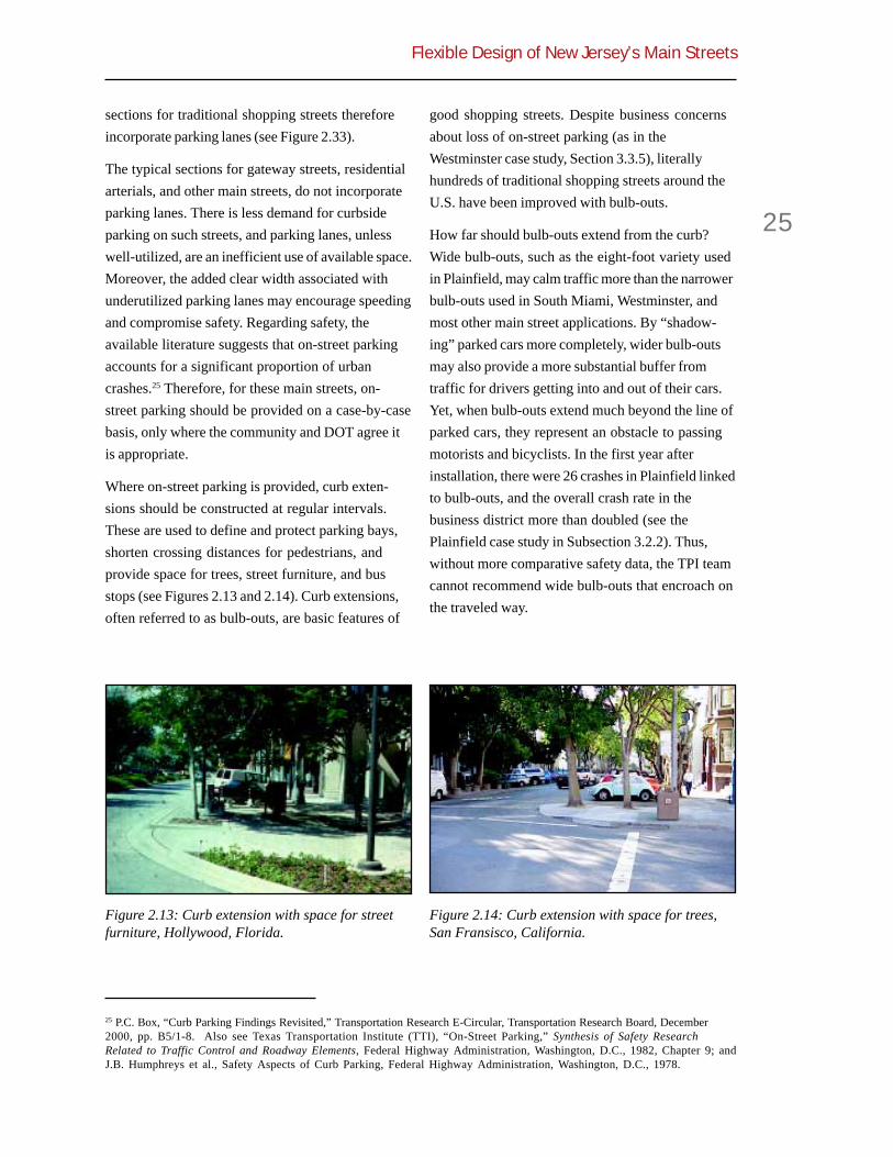
Flexible Design of New Jersey’s Main Streets
25
sections for traditional shopping streets thereforeincorporate parking lanes (see Figure 2.33).
The typical sections for gateway streets, residentialarterials, and other main streets, do not incorporateparking lanes. There is less demand for curbsideparking on such streets, and parking lanes, unlesswell-utilized, are an inefficient use of available space.Moreover, the added clear width associated withunderutilized parking lanes may encourage speedingand compromise safety. Regarding safety, theavailable literature suggests that on-street parkingaccounts for a significant proportion of urbancrashes.25 Therefore, for these main streets, on-street parking should be provided on a case-by-casebasis, only where the community and DOT agree itis appropriate.
Where on-street parking is provided, curb exten-sions should be constructed at regular intervals.These are used to define and protect parking bays,shorten crossing distances for pedestrians, andprovide space for trees, street furniture, and busstops (see Figures 2.13 and 2.14). Curb extensions,often referred to as bulb-outs, are basic features of
good shopping streets. Despite business concernsabout loss of on-street parking (as in theWestminster case study, Section 3.3.5), literallyhundreds of traditional shopping streets around theU.S. have been improved with bulb-outs.
How far should bulb-outs extend from the curb?Wide bulb-outs, such as the eight-foot variety usedin Plainfield, may calm traffic more than the narrowerbulb-outs used in South Miami, Westminster, andmost other main street applications. By “shadow-ing” parked cars more completely, wider bulb-outsmay also provide a more substantial buffer fromtraffic for drivers getting into and out of their cars.Yet, when bulb-outs extend much beyond the line ofparked cars, they represent an obstacle to passingmotorists and bicyclists. In the first year afterinstallation, there were 26 crashes in Plainfield linkedto bulb-outs, and the overall crash rate in thebusiness district more than doubled (see thePlainfield case study in Subsection 3.2.2). Thus,without more comparative safety data, the TPI teamcannot recommend wide bulb-outs that encroach onthe traveled way.
25 P.C. Box, “Curb Parking Findings Revisited,” Transportation Research E-Circular, Transportation Research Board, December2000, pp. B5/1-8. Also see Texas Transportation Institute (TTI), “On-Street Parking,” Synthesis of Safety ResearchRelated to Traffic Control and Roadway Elements, Federal Highway Administration, Washington, D.C., 1982, Chapter 9; andJ.B. Humphreys et al., Safety Aspects of Curb Parking, Federal Highway Administration, Washington, D.C., 1978.
Figure 2.13: Curb extension with space for streetfurniture, Hollywood, Florida.
Figure 2.14: Curb extension with space for trees,San Fransisco, California.

Chapter 2
26
Sidewalks
The RDM establishes a minimum sidewalk width of1.2 meters (four feet). This is a bit skimpy for a mainstreet. Five feet is the accepted minimum sidewalkwidth. This is the minimum clear width of sidewalks,free of obstructions and including shy distances(see Figures 2.15 and 2.16). It will allow a person in awheelchair to turn around or two people pushingstrollers to walk comfortably together. If streetfurniture (street lights, trash cans, newspaper boxes,etc.) is plentiful, an extra 2-1/2 feet of width shouldbe allowed for clearance. If buildings run up to thesidewalk, an additional 1 to 1-1/2 feet of width isdesirable due to the tendency of pedestrians tomaintain this clear distance from walls.
In a main street environment, sidewalk widths wellabove the minimum may be required to accommo-date heavy pedestrian traffic. To allow walking atnear-normal speeds, sidewalks must provide at least25 square feet per pedestrian at peak times.26 Morespace is required, perhaps 40 square feet per person,to permit maneuvering around slower pedestriansand complete avoidance of oncoming and crossingpedestrians. While still lively, all hint of crowding iseliminated at 100 to 150 square feet per person.Given such considerations, it is easy to see howsome leading urban designers have arrived atsidewalk widths of 10, 15, even 20 feet as suitable forhigh-volume locations (as in Figure 2.17).
Pedestrian Crossings
One of the defining qualities of a main street, asopposed to a commercial strip, is a high degree ofinterplay between opposite sides of the street.Shoppers, residents, and other users engage inactivities on one side and then the other, and theeasier a street is to cross, the better a main streetfunctions. Pedestrian movement back and forth
Figure 2.15: Five-foot clear width necessary fortwo strollers, New York, New York.
Figure 2.16: Less than five-foot clear width, WinterPark, Florida.
Figure 2.17: Wider sidewalks where needed,Boston, Massachusetts.
26 J.J. Fruin, Pedestrian Planning and Design, Metropolitan Association of Urban Designers and Environmental Planners,Inc., New York, 1971, pp. 42 and 47-50. Fruin’s work was the basis for Highway Capacity Manual sidewalk standards.

Flexible Design of New Jersey’s Main Streets
27
makes drivers behave less aggressively, which inturn makes the street easier to cross. The twophenomena reinforce each other. Pedestriancrossings may be as important in moderating driverbehavior as geometric design.
On main streets, marked crosswalks should beprovided on all approaches to signal or stop signcontrolled intersections. Marked crosswalks bothchannel pedestrians to a common crossing point andalert drivers to the possibility of pedestrians. Toencourage crossing at such points, and discouragejaywalking, pedestrian delays at signalized intersec-tions should be kept to a reasonable minimum.Research has shown that a minute is the longest thatpedestrians will voluntarily wait before trying tocross against a light. Therefore, main streets shouldhave relatively short traffic signal lengths. Signalsshould be pre-timed in most cases to providecrossing opportunities automatically, without motorvehicle or pedestrian activation. Shorter cycles andpre-timed signals are consistent with low speedtraffic progression, the desired condition on mainstreets.
At controlled intersections, the biggest threat topedestrians is turning conflicts. Motorists makingright turns tend to look to their left for oncomingtraffic rather than their right for crossing pedestri-ans. Motorists making left turns under protected
conditions tend to make turns without carefullyscanning the environment for pedestrians. In NewYork City, the second leading cause (17%) ofpedestrian fatalities is “vehicle turned into pedes-trian in crosswalk.” Drivers are simply not yieldingto pedestrians.
The best way to counter this tendency is to reducepedestrian exposure times and vehicle turningspeeds. Tight corners, curb extensions, medians,and refuge islands will have these effects and arerecommended in subsequent subsections. At keyintersections, there is also the possibility of leadingpedestrian intervals (LPI), which give pedestrianstime to cross before parallel traffic gets its greenlight (see Figures 2.18). In one study, leadingpedestrian intervals were found to reduce vehicle-pedestrian collisions by 64 percent.27
Pedestrian crossing opportunities should be avail-able every 300 feet or so along main streets.Accordingly, some crossings will be located atuncontrolled intersections or midblock locations. Insuch cases, refuge islands and/or curb extensionsshould be used to create safe crosses (see Figures2.19 and 2.20). Marked crosswalks may be used aswell. Recent research suggests that marked cross-walks may or may not improve pedestrian safety,depending on street width and traffic volumes (seeTable 2.8). On wide, high-volume arterials, markedcrosswalks may give pedestrians a false sense ofsecurity. However, for the cross sections recom-mended in this guide, including multilane mainstreets with medians, pedestrians are at least as safewith marked crosswalks as without them, andprobably more comfortable crossing the street.
Particularly at midblock locations, pedestriancrossings should be as attention getting as pos-sible. The MUTCD directs that:
Because non-intersection pedestriancrossings are generally unexpected by theroad user, warning signs should beFigure 2.18: First people (left), then cars (right).
27 M. King, “Calming New York City Intersections,” Urban Street Symposium, Transportation Research Board, Dallas, 1999.

Chapter 2
28
installed and adequate visibility shouldbe provided by parking prohibitions.28
In addition, the MUTCD suggests the use of highvisibility pavement markings at locations wherepedestrians crossings are not expected, such as atmidblock crossings. At such locations, MUTCDfavors diagonal and longitudinal marking patternsover standard transverse parallel lines (right andbottom favored over top in Figure 2.21). Evengreater visibility can be achieved with wider stripesin a Continental pattern (as in Figure 2.22).
Other ways of drawing attention to midblockcrossings include the use of advance warning signs,in-pavement warning lights, and pedestrian-activated signals. Bridgeport Way in University
Place, WA, offers a good example in a suburbansetting (see Figure 2.23). This particular crosssection replaced a five-lane arterial with no provi-sion for pedestrians or bicyclists and crash rates 70percent higher than today.
Medians or Crossing Islands
Recent research has found that raised medianssignificantly reduce pedestrian crash rates onmultilane urban arterials.29 Medians allow pedestri-ans to deal with one direction of traffic at a time, andto cross half way rather than having to wait for agap in traffic in both directions. Where continuousmedians cannot be provided, short crossing islandswill perform as well or better.
Figure 2.19: Curb extensions at a midblockcrossing, West Palm Beach, Florida.
Figure 2.20: Refuge island at a midblock schoolcrossing, Portland, Oregon.
Figure 2.21: MUTCD crosswalk marking patterns.
28 FHWA, op. cit., p. 3B-35.29 Zegeer et al., op. cit. Also see B.L. Bowman and R.L. Vecellio, “Effect of Urban and Suburban Median Types on BothVehicular and Pedestrian Safety,” Transportation Research Record 1445, 1994, pp. 169-179.30 C. Zegeer, J. Stewart, and H. Huang, “Safety Effects of Marked vs. Unmarked Crosswalks at Uncontrolled Locations:Analysis of Pedestrian Crashes in 30 Cities”, Transportation Research Board, July 2000.
Table 2.8: Saftey of marked vs. unmarkedcrossings.30
Marked UnmarkedLanes ADT Median Crossing Crossing
1-2 all — equal
3+ <12,000 — equal
3+ 12,000 - 15,000 yes safer
3+ 12,000 - 15,000 no safer
3+ >15,000 — safer

Flexible Design of New Jersey’s Main Streets
29
No mention is made in the RDM of pedestrian refugeas a function performed by medians, and noconsideration is given to this function in establish-ing minimum median dimensions. While the RDMcalls for medians “as wide as feasible,” widths asnarrow as 1.2 m (4 ft) are acceptable. Such widths areunsafe for bicyclists and pedestrians with carriages,strollers, and other equipment.
Many sources recommend raised medians orcrossing islands on multilane highways. Nearly allrecommend median or island widths of at least 1.8 m(6 ft) for use as pedestrian or bicycle refuges. Thisincludes AASHTO’s Green Book and the oldMUTCD.31 DOT’s own pedestrian guidelines
recommend a median width of 8 feet or more.32 Thus,our typical sections for multilane main streets showraised medians or refuge islands of 6-foot minimumwidth, 8-foot desirable width. If the minimum widthis not attainable, it may be better not to provide anypedestrian refuge at all. Better not to deceivepedestrians into thinking they are safe (compareFigures 2.24 and 2.25 on page 30).
Corner Radii
When it comes to corner radii (curb return radii atintersections), even advocates of context-sensitivedesign, walkable communities, and New Urbanismshy away from bold statements and departures fromstandard practice. It is one thing to reduce travellanes to 11 feet or even 10 feet. This is still widerthan any design vehicle, including a transit bus oran Interstate tractor-semitrailer (with design widthsof 8.5 ft). It is another thing to recommend tightcorners when AASHTO’s design passenger car hasan inside turning radius of 14.4 feet and its designtransit bus and single unit truck have inside turningradii of 24.5 and 28.3 feet, respectively. Simpleturning requirements seem to demand wide corners.
Figure 2.22: High visibility pavement markings,New York, New York (top) and Sacramento,California (bottom).
Figure 2.23: Midblock crossing designed for highvisibility, University Place, Washington.
31 American Association of State Highway and Transportation Officials (AASHTO), A Policy on Geometric Design ofHighways and Streets, Washington, D.C., 2001, p. 630; and Federal Highway Administration (FHWA), Manual on UniformTraffic Control Devices, Washington, D.C., 1988, p. 5B-2. MUTCD 2000 is intentionally silent on geometric issues.32 New Jersey Department of Transportation (NJDOT), Pedestrian Compatible Planning and Design Guidelines, Trenton,1996, p. 31.

Chapter 2
30
In main street contexts, there is general agreementthat the corner radii should be as small as possible.The Green Book itself states: “For arterial streetdesign, adequate radii for vehicle operation shouldbe balanced against the needs of pedestrians...”33
An increase in corner radius from 10 to 30 feet adds15 feet to pedestrian crossing distance and in-creases the turning speed of autos from a crawl toabout 12 mph, putting pedestrians at risk during freeright turns.34
The question, then, is just how small can corner radiibe without jeopardizing safety? In most main streetapplications, the combination of on-street parkingand no-parking zones at corners doubles theeffective or usable corner radius for turning ve-hicles. The actual vehicle fleet requires less spacethan indicated by AASHTO design vehicles, whichare composites. And creative solutions are availablefor the odd case when these two conditions do notapply. The conflicts-solutions matrix in Section 2.6offers a range of possibilities, several of which areillustrated by our case studies:
! Establish an alternate truck route toreduce the need for large radii cornerson main streets (see Figure 2.26).
! Use small corner radii at all but mainintersections with heavy cross streettraffic and large turning volumes (seeFigure 2.27).
33 AASHTO, op. cit., p. 618.34 These estimates come from the Green Book. The former estimate assumes that the sidewalk is set back 10 feet from thecurb.
Figure 2.24: Substandard refuge, Brooklyn, NewYork.
Figure 2.25: Standard refuge, Berkeley, California.
! Use tight mountable corners for theoccasional turning truck, a practiceendorsed by the Technical ReviewCommittee as safe in low-speed mainstreet environments (see Figure 2.28).
! Allow the occasional truck to encroachon the opposing lane briefly, as thetight geometrics of Figure 2.29necessitate. To minimize conflicts insuch cases, stop lines on side streetsmay be set back from intersections farenough to accommodate the sweptpaths of larger vehicles (see Figure2.31).
Corner radii of 10 to 15 feet are common in cities, andcorner radii as small as five to 10 feet prove workablein many locations. Whatever the theoretical case forlarge radii, cities make do with small ones, andcrashes between turning vehicles and side streettraffic appear to be rare, perhaps because turns aremade so cautiously under constrained conditions.
The TPI team recommends that DOT discard itsguidelines for actual corner radii, and instead setstandards for effective or usable corner radiiaccounting for parking and bike lane widths.Practical minimums should be used. Through thekind of creativity shown in our case studies,effective inside corner radii of 15 feet should proveadequate at most minor cross streets, while 25 feetshould be adequate at most major cross streets. On

Flexible Design of New Jersey’s Main Streets
31
corners without curb extensions, the cornersthemselves may have radii of 15 feet or less (as inFigures 2.30, 2.31 and 2.32 on Page 32).
The TPI study team recommends the followingdesign values for use in the Main Street OverlayProgram. Values in bold type would becomecontrolling design elements for designated mainstreets; they could be breached only by designexception.
! Standard Travel Lanes—11 feet.
! Shared Lanes—14 feet (or 13 feet withan edge line and one-foot offset).
! Bike lanes—5 feet—for use at highertraffic volumes and speeds.
! Parking lanes—8 feet—on traditionalshopping streets.
! Sidewalks—5 feet—sized to providepublic space and avoid crowding.
! Medians or Crossing Islands—6 feetand raised or not at all.
! Shoulders—Never on main streets.
! Vertical Curbs—Always on mainstreets.
! Clear Zones—AASHTO minimums forcurbed sections.
! Edge Lines—In rural hamlets andsuburban settings.
! Pedestrian Crossings—Every 300 feetor so—at all controlled intersectionsand other locations with specialtreatments.
! Corner Radii—Effective inside radii of15 feet at minor cross streets, 25 feet atmajor streets.
! Traffic Signals—Timed for 60-secondmaximum pedestrian wait.
Figure 2.29: Twenty-foot corner with plannedencroachment, Plainfield, New Jersey.
Figure 2.28: Fifteen-foot mountable corner, SouthMiami, Florida.
Figure 2.27: Five-foot corner at minor intersection,Westminster, Maryland.
Figure 2.26: Twenty-foot corner with alternatetruck route, York, Pennsylvania.
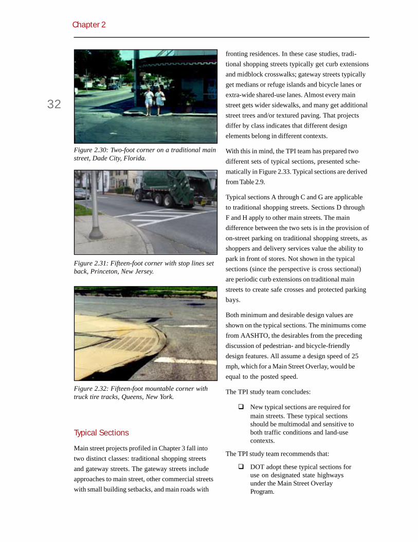
Chapter 2
32
Typical Sections
Main street projects profiled in Chapter 3 fall intotwo distinct classes: traditional shopping streetsand gateway streets. The gateway streets includeapproaches to main street, other commercial streetswith small building setbacks, and main roads with
fronting residences. In these case studies, tradi-tional shopping streets typically get curb extensionsand midblock crosswalks; gateway streets typicallyget medians or refuge islands and bicycle lanes orextra-wide shared-use lanes. Almost every mainstreet gets wider sidewalks, and many get additionalstreet trees and/or textured paving. That projectsdiffer by class indicates that different designelements belong in different contexts.
With this in mind, the TPI team has prepared twodifferent sets of typical sections, presented sche-matically in Figure 2.33. Typical sections are derivedfrom Table 2.9.
Typical sections A through C and G are applicableto traditional shopping streets. Sections D throughF and H apply to other main streets. The maindifference between the two sets is in the provision ofon-street parking on traditional shopping streets, asshoppers and delivery services value the ability topark in front of stores. Not shown in the typicalsections (since the perspective is cross sectional)are periodic curb extensions on traditional mainstreets to create safe crosses and protected parkingbays.
Both minimum and desirable design values areshown on the typical sections. The minimums comefrom AASHTO, the desirables from the precedingdiscussion of pedestrian- and bicycle-friendlydesign features. All assume a design speed of 25mph, which for a Main Street Overlay, would beequal to the posted speed.
The TPI study team concludes:
! New typical sections are required formain streets. These typical sectionsshould be multimodal and sensitive toboth traffic conditions and land-usecontexts.
The TPI study team recommends that:
! DOT adopt these typical sections foruse on designated state highwaysunder the Main Street OverlayProgram.
Figure 2.30: Two-foot corner on a traditional mainstreet, Dade City, Florida.
Figure 2.31: Fifteen-foot corner with stop lines setback, Princeton, New Jersey.
Figure 2.32: Fifteen-foot mountable corner withtruck tire tracks, Queens, New York.

Flexible Design of New Jersey’s Main Streets
33
Figure 2.33: Typical cross sections for main streets.
Table 2.9: Main street design controls and cross sections.
Section A
Section B
Section C
Section G
Section H
Section D
Section E
Section F
Land Use Average Annual Parking Bike SectionContext Daily Traffic Lane Lane Median (Figure 2.34)
>10000 X X A
2000-10000 X B
<2000 X C
higher volumes X X X G
>10000 X D
2000-10000 E
<2000 F
higher volumes X X H
TraditionalShoppingStreet
OtherMainStreet

Chapter 2
34
2.5 Traffic CalmingIn the TPI survey of New Jersey localities, threelocalities with recent DOT work on their main streetsexpressed dissatisfaction with resulting speeds. Twohad wanted traffic calming elements to be part ofthese projects (see Appendix A.3).
These localities are caught in a vicious cycle. Theirmain streets are designed for speeds well above theposted speed. Since vehicle operating speeds oftenexceed design speeds, speed surveys done at somelater date will likely find 85th percentile speeds highenough to justify raising speed limits. Higher speedlimits, in turn, will raise minimum design speeds forall future roadwork. The result: current New Jerseypolicies do not discourage, and may actuallyencourage, higher speeds on main streets.
Nature of Traffic Calming
Traffic calming is integral to context-sensitivedesign in Europe.35 Europeans use physical designto “enforce” low operating speeds and roadwayappearance to “explain” to motorists how theyshould behave on a given roadway. Hence the useof the terms “self-enforcing” and “self-explaining”to describe the European approach to CSD.36
In a couple of case studies, sponsors referred totheir main streets as “traffic calmed.” They stretchthe definition. Not to detract from the projectsstudied, for they are laudable by United Statesstandards, but all fall short of the best Europeanexamples of traffic-calmed main streets (see Figure2.34). We may beautify our main streets, or makethem more pleasant to walk or bicycle along andeasier to cross. But we seldom apply traffic calmingmeasures, which compel motorists to slow down.When we begin narrowing our main streets to 18feet or less at choke points, raising our intersections
to sidewalk level, inserting dramatic lateral shiftsinto their alignments, and generally followingEuropean practice, we can lay claim to traffic calmedmain streets—but not until.
Only one of our 15 case studies entails anything likeEuropean traffic calming, that being the redesignedMarket Street in York, Pennsylvania (see Figure2.35). Not only is Market Street choked down, but ashift in alignment produces lateral forces onmotorists that cause them to slow down naturally.This tendency to slow down on curves does notrequire police enforcement, or heavy pedestriantraffic, or drivers pulling in and out of parkingspaces. In this sense, it is self-enforcing 24 hours aday.
35 R. Ewing, Traffic Calming: State-of-the-Practice, Institute of Transportation Engineers/Federal Highway Administration,Washington, 1999, Chapter 9.36 J. Brewer et al., Geometric Design Practices for European Roads, Federal Highway Administration, Washington, D.C.,2001.
Figure 2.34: Traffic calmed main street inRecklinghausen, Germany.
Figure 2.35: Traffic calmed main street in York,Pennsylvania.

Flexible Design of New Jersey’s Main Streets
35
Lower Design Speeds
The TPI study team compared New Jersey’s designstandards and design exception policies to those ofseveral other states (see Section 2.3). Designspeeds, it turns out, are treated differently in NewJersey. Most other states have set minimum designspeeds by facility type and allow design exceptionsto these standards in low-speed environments.
High design speeds are promoted in the RDM: “Forthrough roads, every effort should be made to useas high a design speed as practicable to attain adesired degree of safety, mobility and efficiency.”DOT backs into design speeds through postedspeed limits (see Table 2.10), and excludes designspeed from the set of controlling design elementssubject to design exceptions (see Table 2.11). GivenNew Jersey’s presumptive speed limit in businessdistricts of 25 mph, the minimum design speed forexisting main streets is 50 kph (30 mph) and for newmain streets is 60 kph (35 mph). These speeds aretoo high for most main street applications. Comparethese to Vermont’s minimum design speed for urbanarterials (as low as 40 kph or 25 mph) or Idaho’s (aslow as 30 kph or 19 mph). These two states tookadvantage of the flexibility in ISTEA to adopt sub-AASHTO design standards for non-NHS roads.Design speed was among the few AASHTOminimums they considered too high (see Table 2.12).
A reasonable minimum design speed for traditionalmain streets might be 25 or even 20 mph. For theirtraffic calmed streets, the British have established 20mph per hour zones, and northern Europeans 30 kph(19 mph) zones. Traffic calming measures are used toenforce these low speed limits. Pedestrians andmotor vehicles comfortably coexist at such speeds.Pedestrian-motor vehicle crashes are rare at thesespeeds, and, when they occur, are seldom fatal. TheBritish main street in Figure 2.36 is traffic calmed bymeans of a raised crosswalk and lateral shifts. Theaverage travel speed is only 20 mph.
Table 2.10: New Jersey design speeds in relation toposted speeds.
Table 2.11: New Jersey controlling designelements.
Table 2.12: Sub-AASHTO design standardsadopted by three states.
Cross SlopeTravel Lane WidthShoulder Width
Horizontal Curve RadiusGrade
Stopping Sight DistanceIntersection Sight Distance
SuperelevationAuxiliary Lane Length
Through Lane Drop Transition LengthBridge Width
Structural CapacityVertical Clearance to Structures
Posted Speed Design Speed
Existing New
25 mph 50 kph (30 mph) 60 kph (35 mph)
30 mph 60 kph (35 mph) 60 kph (35 mph)
35 mph 60 kph (35 mph) 70 kph (40 mph)
CT ID VT
Design Speed X XDesign Year Volume X XLevel-of-Service XTravel Lane Width XParking Lane Width XShoulder WidthIntersection Sight Distance XStopping Sight Distance XHorizontal Curvature XVertical CurvatureMaximum Grade X XHorizontal ClearanceVertical ClearanceGradeSuperelevation

Chapter 2
36
Policies, Procedures, and Standards
The recently revised New Jersey State Plan specifi-cally encourages:
...the use of traffic calming techniques toenhance pedestrian and bicycle circula-tion and safety within compact communi-ties and other locations where local traveland land access are a higher priority thanregional travel.
In its draft “bridging” document, even AASHTOendorses traffic calming in certain settings:
In general, the designer should considertraffic calming measures as a tool toaddress congestion, safety, and quality oflife issues in response to one or more of the
following:
1. …
2. A project is scheduled for avillage/main street, school zone, or othersubarea, and scoping indicates thatinclusion of traffic calming would satisfyidentified subarea needs such as asignificant existing safety problem whoseseverity could reasonably be expected tobe reduced by the application of trafficcalming...37
About a half dozen state DOTs have begun topromote traffic calming. Virginia has a pilot program,Pennsylvania and South Carolina have illustratedguidebooks, and New York has application guide-lines and a training program. Illinois and Vermont arejust beginning initiatives. The most ambitious effortto date is in Delaware. The Delaware Department ofTransportation (DelDOT) has established a trafficcalming program, developed a traffic calming designmanual, and incorporated the manual, through therule-making process, into the state’s roadway designmanual (see Figure 2.37). The traffic calming designmanual prescribes standard procedures for planningand implementing traffic calming; establisheswarrant-like guidelines for when and where differenttraffic calming measures may be deployed; providestypical geometric designs for different measures and
Figure 2.37: Delaware’s typical chicane.
Figure 2.36: Traffic calmed to 20 mph.
37 American Association of State Highway and Transportation Officials (AASHTO), “Context-Sensitive Design forIntegrating Highway and Street Projects with Communities and the Environment,” Highway Geometric Elements—DesignAnd Safety Considerations, NCHRP 20-17-114, final draft, March 2000, p. 29.

Flexible Design of New Jersey’s Main Streets
37
a range of acceptable design alternatives; andestablishes standard signing and marking practicesfor each measure.
DOT has the option of traffic calming its mainstreets on an ad hoc basis, or establishing policies,procedures, and standards for main street trafficcalming as Delaware did. DelDOT chose to institu-tionalize and codify traffic calming after the ad hocapproach produced public discord in two highprofile cases.
The TPI study team concludes:
! To actively engage in European-styletraffic calming, DOT would need tolower design speeds on main streetsand develop traffic calming policies,procedures, and standards.
The TPI study team recommends that:
! DOT allow design speeds of 25 mphon main streets, equal to the minimumposted speed. This speed should bemade self-enforcing via traffic calmingmeasures.
! DOT consider seeking statutoryauthority for design and postedspeeds of 20 mph on traditionalshopping streets. Again, this speedshould be made self-enforcing viatraffic calming measures.
! DOT develop traffic calming guidelinesfor incorporation into its RoadwayDesign Manual. The Delaware TrafficCalming Design Manual provides agood starting point for New Jersey.
2.6 Conflicts-SolutionsMatrixPrevious sections recommend process changes,design overlays, and new manuals as means offostering context-sensitive main street design. Yet,as high-level DOT staff stress, such changes areless critical than the exercise of common sense andcreativity on the part of highway designers. Ifdesigners understand the environmental and
community context, and the safety and mobilityneeds to be addressed, common sense and creativ-ity will usually produce designs that meeteveryone’s objectives.
To assist designers in this regard, a conflict-solutions matrix was developed. The matrix isintended as a reference for use in everyday designactivities. Case studies were also prepared and arepresented in the next chapter. They are replete withexamples of creative thinking and problem solving inmain street contexts.
The matrix has two parts. The first part considerseach roadway design control or standard in turn,indicates its effect on roadway geometrics, presentsthe purpose of the standard from a DOT perspec-tive, identifies the nature and magnitude of conflictswith local objectives, and suggests design solutionsthat may lessen conflicts without unduly compro-mising DOT purposes. The second part is theconverse of the first. It considers each pedestrian-friendly design feature in turn, presents its purpose,identifies potential conflicts with DOT purposes,and indicates how these conflicts can be minimized.
The matrix was developed with the assistance of theTechnical Review Committee (TRC). It incorporatesideas from guidance documents on pedestrian-friendly roadway design, and even more so,workable ideas from our case studies. References areprovided in the matrix to the guidance documentsand case studies that served as sources or illustra-tions of particular ideas. Designers are referred tothe guidance documents and case studies for moredetailed information.
At one point, the project team attempted to screenand prioritize solutions. This proved unworkable.Instead, the final matrix presents ideas for furtherconsideration, and encourages designers to judgetheir applicability on a case-by-case basis.
In sum, the conflicts-solutions matrix offers a rangeof possibilities for reconciling the local desire forpedestrian convenience and safety with DOT’spolicy of accommodating the entire traffic mix.
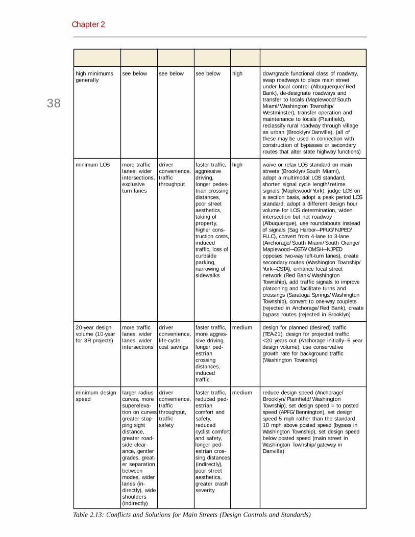
Chapter 2
38
Design Control Geometric Design Sources Magnitude Potential Solutionsor Standard Effects Impetus of Conflict of Conflict
high minimums see below see below see below high downgrade functional class of roadway,generally swap roadways to place main street
under local control (Albuquerque/RedBank), de-designate roadways andtransfer to locals (Maplewood/SouthMiami/Washington Township/Westminster), transfer operation andmaintenance to locals (Plainfield),reclassify rural roadway through villageas urban (Brooklyn/Danville), (all ofthese may be used in connection withconstruction of bypasses or secondaryroutes that alter state highway functions)
minimum LOS more traffic driver faster traffic, high waive or relax LOS standard on mainlanes, wider convenience, aggressive streets (Brooklyn/South Miami),intersections, traffic driving, adopt a multimodal LOS standard,exclusive throughput longer pedes- shorten signal cycle length/retimeturn lanes trian crossing signals (Maplewood/York), judge LOS on
distances, a section basis, adopt a peak period LOSpoor street standard, adopt a different design houraesthetics, volume for LOS determination, widentaking of intersection but not roadwayproperty, (Albuquerque), use roundabouts insteadhigher cons- of signals (Sag Harbor—PFUG/NJPED/truction costs, FLLC), convert from 4-lane to 3-laneinduced (Anchorage/South Miami/South Orange/traffic, loss of Maplewood—OSTA/OMSH—NJPEDcurbside opposes two-way left-turn lanes), createparking, secondary routes (Washington Township/narrowing of York—OSTA), enhance local streetsidewalks network (Red Bank/Washington
Township), add traffic signals to improveplatooning and facilitate turns andcrossings (Saratoga Springs/WashingtonTownship), convert to one-way couplets(rejected in Anchorage/Red Bank), createbypass routes (rejected in Brooklyn)
20-year design more traffic driver faster traffic, medium design for planned (desired) trafficvolume (10-year lanes, wider convenience, more aggres- (TEA-21), design for projected trafficfor 3R projects) lanes, wider life-cycle sive driving, <20 years out (Anchorage initially—5 year
intersections cost savings longer ped- design volume), use conservativeestrian growth rate for background trafficcrossing (Washington Township)distances,inducedtraffic
minimum design larger radius driver faster traffic, medium reduce design speed (Anchorage/speed curves, more convenience, reduced ped- Brooklyn/Plainfield/Washington
supereleva- traffic estrian Township), set design speed = to postedtion on curves, throughput, comfort and speed (APFG/Bennington), set designgreater stop- traffic safety, speed 5 mph rather than the standardping sight safety reduced 10 mph above posted speed (bypass indistance, cyclist comfort Washington Township), set design speedgreater road- and safety, below posted speed (main street inside clear- longer ped- Washington Township/gateway inance, gentler estrian cros- Danville)grades, great- sing distanceser separation (indirectly),between poor streetmodes, wider aesthetics,lanes (in- greater crashdirectly), wide severityshoulders(indirectly)
Table 2.13: Conflicts and Solutions for Main Streets (Design Controls and Standards)

Flexible Design of New Jersey’s Main Streets
39
Table 2.13: Conflicts and Solutions for Main Streets (Design Controls and Standards)
Design Control Geometric Design Sources Magnitude Potential Solutionsor Standard Effects Impetus of Conflict of Conflict
large design wider lanes, traffic safety, faster traffic, medium establish alternate truck route (York),vehicle wider accommoda- higher turning prohibit turns by large vehicles, use
intersections tion of large speeds, different design vehicles at differentvehicles, longer ped- intersections, use one design vehicleemergency estrian for thru movements, another for turnsresponse crossing
distances
adoption of a wider streets, design faster traffic, high, use multiple sections along a stretch ofsingle typical abrupt transi- standardiza- poor street medium road (Anchorage/Albuquerque/Sagsection tions from tion, reduced aesthetics Harbor/Saratoga Springs/South Miami),
rural to urban liability (out of scale discontinue use of typical sectionswith surround- (Maryland)ings), higherconstructioncosts
minimum lane wider streets traffic safety, faster traffic, medium adopt lower design speed, reduce lanewidth accommoda- longer ped- width standard (Sag Harbor - may require
tion of large estrian design exception—down to 10'), (invehicles crossing suburban context, apply NJDOT low cost
distances, safety measures)higherconstructioncosts
minimum wider streets traffic safety, faster traffic, medium, use colored or textured materials inshoulder width speed longer ped- high shoulders (OMSH on rural-urban
enforcement, estrian transitions), eliminate shoulders onbreakdown crossing urban streets (Albuquerque/Danville/lane, bicycle distances, Sag Harbor), use narrow shoulderssafety suggestion of (Brooklyn/Bennington/Washington
rural design, Township), substitute parking lanes forhigher shoulders (Sag Harbor), use gutterconstruction pans in lieu of shoulders (as long ascosts, unsafe "bike safe") (Anchorage/Orlando)passingmaneuvers
minimum corner wider accommoda- high turning high use mountable curbs at corners with(curb return) intersections tion of large speeds, long vertical elements set back from theradius vehicles, pedestrian curbs (South Miami), establish alternate
traffic safety, crossing truck routes (York), use wide outsidefaster distances, traffic, parking, or bicycle lanes toemergency poor street increase effective radius (APFG—useresponse aesthetics effective turning radius), adopt
substandard corner radii (South Miami/York), use compound curves at corners(Brooklyn—OMSH), use simple radiuscurves with tapers at corners (OMSH), setback stop lines on side streets, placecrosswalks upstream/downstream of curbreturn (Plainfield/York—PM), use largercorner radii in combination with curbextensions (Maplewood/York), design forlarger vehicles only at selectedintersections (Anchorage/Westminster),accept large vehicles crossing the centerline (Plainfield), compute effective radiusat corners considering parking lanes,setback stop lines on side streets to allowwider turns off main streets, installtriangular islands of special design tocreate slip lanes (PFUG/NJPED)

Chapter 2
40
Table 2.13: Conflicts and Solutions for Main Streets (Design Controls and Standards)
Design Control Geometric Design Sources Magnitude Potential Solutionsor Standard Effects Impetus of Conflict of Conflict
minimum no chicanes, traffic safety, faster traffic, low (not mark and sign as traffic calminghorizontal curve lateral shifts, driver comfort taking of generally a measures, recalculate minimum curveradius or traffic property, problem radius, adopt lower speed limit on
circles (if higher on main curve, display lower advisory speed,interpreted construction streets accept design speed below postedliterally) costs except in speed (Danville), (in suburban context,
connection apply NJDOT low cost safety measures)with trafficcalming)
minimum vertical no speed traffic safety faster traffic, low (not mark and sign as traffic calmingcurve radius humps or higher generally a measures, recalculate minimum curve
tables (if construction problem radius, adopt lower speed limit oninterpreted costs on main curve, display lower advisory speed,literally) streets (in suburban context, apply NJDOT
except in low cost safety measures)connectionwith trafficcalming)
minimum straighter traffic safety, faster traffic, medium, provide warning signs and lower advisorystopping sight sections, pedestrian taking of low speeds, recalculate stopping sightdistance wider road- safety property, distances based on new research
side clearance tree removal
right-turn lanes wider driver longer ped- medium, eliminate turn lanes on main streets (PMintersections convenience, estrian low with bike traffic), set crosswalks back on
traffic crossing side streets to provide yield space outthroughput distances, of traffic flow (York), install triangular
turning islands of special design to create slipconflicts with lanes (Sag Harbor—PFUG), allow right-pedestrians turn-on-red from shared lanes, usecrossing side narrow right-turn lanesstreets
left-turn lanes wider driver longer low convert from 4-lanes to 3-lanes with left-intersections convenience, pedestrian turn pockets (Maplewood/South Miami/
traffic safety, crossing South Orange), eliminate turn lanes ontraffic distances, main streets (Brooklyn—OMSH for left-throughput longer turn stacking lanes), use narrow left-turn
pedestrian lanes, install pedestrian refuge islandscrossing adjacent to left-turn lanes, convert to one-delays, way couplets, route left turns aroundturning block via right turns , convert fromconflicts with 4-lanes to 3-lanes with continuous left-pedestrians turn lanescrossing sidestreets
speed-change wider streets driver faster traffic, medium eliminate acceleration lanes on mainlanes convenience, more streets (Brooklyn—climbing lanes
traffic safety aggressive rejected—OMSH)at high driving,speeds longer
pedestriancrossingdistances,suggestion ofrural design,conflicts withbicyclists

Flexible Design of New Jersey’s Main Streets
41
Table 2.13: Conflicts and Solutions for Main Streets (Design Controls and Standards)
PFUG—FHWA Pedestrian Facilities Users GuideNJPED—New Jersey Pedestrian Design GuidelinesOSTA—Oregon Special Transportation AreasAPFG—AASHTO Pedestrian Facilities GuideOMSH—Oregon Main Street HandbookPM—Portland Metro Street Design GuidelinesFLLC—Florida Livable Communities Directive
Design Control Geometric Design Sources Magnitude Potential Solutionsor Standard Effects Impetus of Conflict of Conflict
through-lane drop shadow lanes traffic safety faster traffic, low, drop lane prior to an intersection andtransition length for lane drop more medium add turn pockets (Saratoga Springs),
at intersec- aggressive adopt lower design speeds, establishtions (even if driving, poor lower advisory speeds, use mountablemarked as street curbs and breakaway elements on farturn lane) aesthetics, side of intersection (Saratoga Springs)
suggestion ofrural design,conflicts withbicyclists
shifting lane gentler lateral traffic safety faster traffic low mark and sign lateral shifts as traffictransition length shifts calming measures (York), adopt lower
design and posted speeds, establishlower advisory speeds
right turn on red driver turning con- medium eliminate RTOR on main streets (APFG/convenience, flicts with OSTA/NJPED), allow RTOR with yield-to-traffic pedestrians pedestrians signingthroughput crossing side
streets
minimum lateral wider median traffic safety, poor street low place trees behind vertical curbsclearances islands (if pedestrian aesthetics, (Bennington—only 1 ½'/York - only 2'),
trees planted visibility, reduced plant smaller trees of yielding varietyin median), room for sidewalk (Saratoga Springs), lower design andwider ROW utilities clear width posted speeds (Saratoga Springs),(if trees use object markers with mature treesplanted onedge)
offsets at curbs wider streets, traffic safety faster traffic, medium waive or reduce offset requirements, use(both edge and narrower longer mountable curbs, lower design andmedian) sidewalks, pedestrian posted speeds
narrower crossingmedian distancesislands, pooralignmentbetween old& new curbs
MUTCD marking traffic safety, poor street low, relax MUTCD requirements on mainand signing pedestrian aesthetics medium streets, use landscaping to draw attentionrequirements safety, to hazards, use textured surfaces to draw
universal attention to hazards, install and removerecognition portable signage as needed

Chapter 2
42
Table 2.14: Conflicts and Solutions for Main Streets (Pedestrian-Friendly Features)
Pedestrian Design Sources Value to Potential SolutionsFriendly Features Impetus of Conflict Pedestrians
narrow down slower traffic, traffic safety high narrow street at midblock but maintain intersectionstreets pedestrian capacity, eliminate underutilized parking lane,(Anchorage/ safety, space narrow oversized lanes to make room for otherAtlanta/ for wider design elements (Atlanta)Maplewood/Sag sidewalks,Harbor/South bike lanes,Miami—PFUG) etc.
widen sidewalks pedestrian less cross high relate sidewalk width to land use intensity, provide(Anchorage/ comfort, sectional a clear width free of street furniture (PFUG), turnAtlanta/ space for width for over sidewalk maintenance to locals or otherMaplewood/ street furn- traffic, higher agencies (Anchorage/Maplewood/Plainfield/Plainfield/Red iture, space construction Saratoga Springs/York)Bank/Saratoga for sidewalk and main-Springs/South activity tenance costMiami/WashingtonTownship/York—sidewalks addedin Albuquerque/University Place—PFUM/PM/FLLC)
mark crosswalks pedestrian false sense medium place street lights at crossings (OMSH/NJPED),at intersections saftey of security for install traffic signals to create gaps in trafficon all approaches pedestrians (Washington Township/Saratoga Springs), use high(Bennington/ visibility crosswalk markings such as ladderSouth Orange/ pattern (PFUG/OSTA/ OMSH/NJPED), extend curbs atYork—PM) crossings to reduce exposure time (many places—
NJPED), place pedestrian refuge islands at crossings,install pedestrian-activated flashing inset warninglightsplace only on selected approaches (Maplewoodand Saratoga Springs), use textured surface oncrosswalks, use textured surface at edges of cross-walks (OMSH), use reflective inlay tape on crosswalks(PFUG), raise crosswalks to sidewalk height or justbelow, use "countdown" signals, use audible ped-estrian signals (Burlington), place stop lines back fromcrosswalks (Maplewood)
provide pedestrian driver medium install automated pedestrian detection, providepedestrian push- convenience, convenience walk phase on every cycle, provide leading walkbuttons and signal pedestrian phase prior to cross street movement (South Orange)heads (Saratoga safety,Springs—PM/ complianceNJPED/FLLC) with ADA
provide raised pedestrian snow removal high turn over landscape maintenance to localsmedians on wide refuge, street problems, (Anchorage/Saratoga Springs), use minimumstreets beautification, landscape median width (Maplewood below minimum with 4'/(Anchorage/ access maintenance, University Place at minimum with 6-11'), place trees,Maplewood/ management, increased object markers, etc. on islands for delineation inSaratoga Springs/ presumed construction snow, use bollards and/or textured surfaces withoutUniversity Place— slower traffic, cost, possible landscaping, widen medians at locations without on-NJPED) traffic safety increased street parking, make medians mountable
speeds (Maplewood), install pedestrian pushbuttons inmedians (NJPED)
provide center pedestrian landscape medium turn over landscape maintenance to locals (Sagrefuge islands refuge, street maintenance, Harbor), alternate between center islands and on-(where not pos- beautification, increased street parking bayssible to provide a slower traffic constructionrelatively contin- if done with cost, conflictuous median) deflection with on-street(Sag Harbor/ parkingSouth Orange—PFUG/PM/FLLC)

Flexible Design of New Jersey’s Main Streets
43
Table 2.14: Conflicts and Solutions for Main Streets (Pedestrian-Friendly Features)
Pedestrian Design Sources Value to Potential SolutionsFriendly Features Impetus of Conflict Pedestrians
create gateways slower traffic, traffic safety, medium turn over maintenance to locals (Danville/Saratoga(Danville/Sag smoother landscape Springs), use monument signage and other verticalHarbor/Saratoga transition maintenance, elements to mark gateways (Danville/Sag Harbor),Springs/South from rural to textured install rumble strips for pre-warning (Sag Harbor),Orange—OSTA) urban surface install street lights at gateways (Sag Harbor)
maintenance
install barrier pedestrian wider streets medium adopt lower design speed, use higher curbs to deflectcurbs (curb and safety and due to offsets, vehicles at low speeds, place fixed objects behindgutter added in comfort, higher curbs, use mountable beveled curbs (SaratogaAlbuquerque/ inability to construction Springs)Saratoga Springs/ park on costs, vehicleUniversity Place) street edge, instability
suggestion of upon high-urban design speed impact,
false securityfor ped-estrians, lossof emergencyparking
install curb ramps pedestrian higher high use median cutouts rather than median ramps,and median comfort and construction provide detectable warning at ramps and cutouts forchannel (two safety, costs, wider visually impaired, use diagonal curb ramps onlyramps per corner compliance streets (if use where diagonal crossings allowed—PFUG/NJPED) with ADA curb ramps
on medians)
provide bicycle bicycle wider street, low, use colored surface on bike lanes (Sag Harbor—PFUG/lanes comfort and faster traffic, medium PM through intersections), avoid right-turn lanes on(Albuquerque/ safety, driver bicycle main streets, separate from traffic lane with extraSag Harbor/ convenience, conflicts with wide stripes (8" in Sag Harbor), adopt low designUniversity Place/ improved right-turning speed so bikes can use traffic lanes, use extra-wideWashington sight distance traffic, bicycle curb lanes so bikes can share traffic lanes (SagTownship—PFUG/ at intersec- conflicts with Harbor/Saratoga Springs/South Orange—PM at lowerFLLC) tions, traffic parked cars, ADT), separate from traffic lane with flush reflectors
buffer for bicycle con- (Sag Harbor), recess drainage inlets (as opposed topedestrians, flicts with using catch basins) (PM), use bicycle-friendly drainagepull-out space pedestrians, grates (Bennington), provide offset from parking lane,for deliveries impression provide gutter pan wide enough for bikes (Anchorage/
that bicyclists Orlando), eliminate on-street parking (particularlyshould ride angled), extend bicycle lanes to intersection (PM),only on provide skip markings through intersection (PM),marked place bicycle lanes between through and turn lanes,streets place bicycle lanes on parallel routes
install midblock pedestrian presumed medium, place temporary object markers at crosswalks, usecrosswalks convenience, pedestrian high (depend- high visibility crosswalk markings (OSTA and PM),(Plainfield/South traffic through- danger, ing on block install flashing overhead beacons, place street lightsOrange/University put at driver length) at crossings (OMSH/NJPED), extend curbs at crossingsPlace/ intersections incon- to reduce exposure time (Plainfield/South Orange/Westminster/York venience Westminster/York), place pedestrian refuge islands at—PM/FLLC) crossings, install pedestrian-activated flashing inset
warning lights (University Place), provide pedestrianactivated traffic signals (NJPED), use textured surfaceon crosswalks (South Orange/Westminster), line upmidblock crosswalks with alleys (Maplewood/SouthOrange), use textured surface at edges of crosswalks(OMSH), raise crosswalks to sidewalk height or justbelow, angle median cut-out to increase pedestrianvisibility, limit midblock crosswalks to long blocks(NJPED)
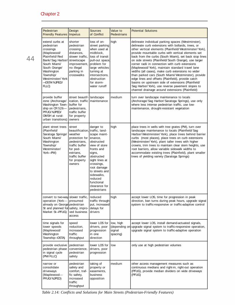
Chapter 2
44
Table 2.14: Conflicts and Solutions for Main Streets (Pedestrian-Friendly Features)
Pedestrian Design Sources Value to Potential SolutionsFriendly Features Impetus of Conflict Pedestrians
extend curbs at shorter loss of on- high delineate individual parking spaces (Westminster),pedestrian pedestrian street parking delineate curb extensions with bollards, trees, orcrossings crossing when used at other vertical elements (Plainfield/Westminster/York),(Maplewood/ distances, midblock, provide mountable curbs with vertical elements setPlainfield/Red slower traffic, loss of transit back from the curbs (South Miami), set back stop linesBank/Sag Harbor/ streetscape pull-out space, on side streets (Plainfield/South Orange), use largerSouth Miami/ improvement, problem for corner radii in connection with curb extensionsSouth Orange/ no illegal large vehicles (Maplewood/York), maintain standard travel laneWashington parking in turning at widths (all cases), make curb extensions no widerTownship/ crosswalks intersections, than parked cars (South Miami/Westminster), provideWestminster/York obstruction edge lines and offsets (Plainfield), provide catch—OSTA/NJPED/ for storm- basins on upstream side of extensions (Plainfield/FLLC) water runoff Sag Harbor/York), use reverse pavement slopes to
channel drainage around extensions (Plainfield)
provide buffer street beautif- landscape medium turn over landscape maintenance to localszone (Anchorage/ ication, traffic maintenance (Anchorage/Sag Harbor/Saratoga Springs), use onlyWashington Town- buffer for where less intense pedestrian traffic, use low-ship on CR 526— pedestrians, maintenance, drought-resistant vegetationPFUG/NJPED/ traffic bufferOMSH at rural- for propertyurban transitions) owners
plant street trees street danger to high place trees in wells with tree grates (PM), turn over(Plainfield/ beautification, traffic, land- landscape maintenance to locals (Plainfield/SagSaratoga Springs/ weather scape maint- Harbor/Westminster/York), place trees behind barrierSouth Miami/ protection for enance, curbs (most places), place trees on curb extensionsWashington pedestrians, obstructed (Westminster/York), plant taller trees with higherTownship/ traffic buffer view of store crowns, trim trees to maintain clear stem heights, useWestminster/ for ped- fronts and root barriers, allow variable sidewalk widths toYork—PM) estrians, signs, accommodate existing trees (Plainfield), plant smaller
traffic buffer obstructed trees of yielding variety (Saratoga Springs)for property sight lines atowners crossings,
root damageto streets andsidewalks,reducedfunctionalclearance forpedestrians
convert to two-way slower traffic, reduced high accept lower LOS, time for progression in peakoperation (York— presumed traffic through- direction, ban turns during peak hours, upgrade signalalready on George pedestrian put, increased system to traffic-responsive or traffic-adaptive controlSt and planned for safety, impro- delays forMarket St—PFUG) ved business drivers
access
time signals for speed lower LOS for low, high accept lower LOS, install demand-actuated signals,lower speeds reduction, drivers, poor (depending on upgrade signal system to traffic-responsive operation,(Maplewood/ increased progression signal upgrade signal system to traffic-adaptive operationWashington traffic in one spacing)Township—OSTA) throughput direction
provide exclusive pedestrian lower LOS for low only use at high pedestrian volumespedestrian phase convenience, drivers, poorin signal cycle pedestrian progression(PM/FLLC) safety
narrow or pedestrian taking of medium other access management measures such asconsolidate safety and property or continuous medians and right-in, right-out operationdriveways comfort, traf- easements, (PFUG), provide median dividers on wide driveways(Maplewood— fic safety, business (PFUG)PFUG/NJPED) increased opposition
trafficthroughput
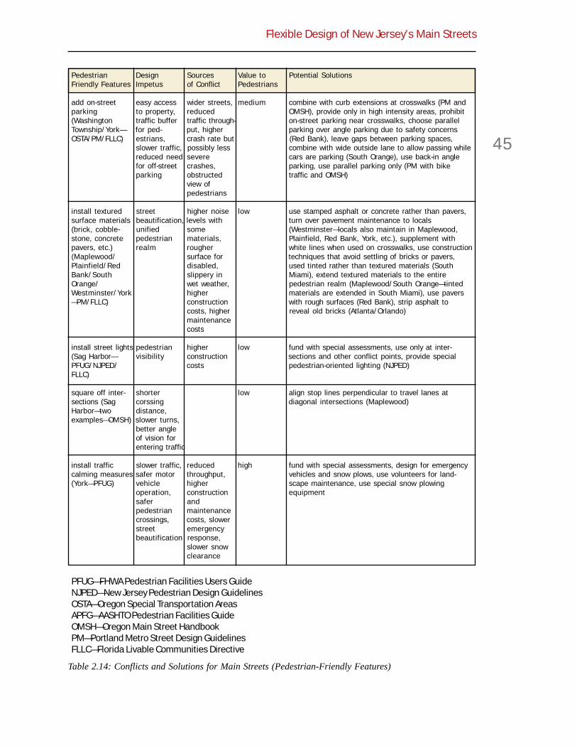
Flexible Design of New Jersey’s Main Streets
45
PFUG—FHWA Pedestrian Facilities Users GuideNJPED—New Jersey Pedestrian Design GuidelinesOSTA—Oregon Special Transportation AreasAPFG—AASHTO Pedestrian Facilities GuideOMSH—Oregon Main Street HandbookPM—Portland Metro Street Design GuidelinesFLLC—Florida Livable Communities Directive
Table 2.14: Conflicts and Solutions for Main Streets (Pedestrian-Friendly Features)
Pedestrian Design Sources Value to Potential SolutionsFriendly Features Impetus of Conflict Pedestrians
add on-street easy access wider streets, medium combine with curb extensions at crosswalks (PM andparking to property, reduced OMSH), provide only in high intensity areas, prohibit(Washington traffic buffer traffic through- on-street parking near crosswalks, choose parallelTownship/York— for ped- put, higher parking over angle parking due to safety concernsOSTA/PM/FLLC) estrians, crash rate but (Red Bank), leave gaps between parking spaces,
slower traffic, possibly less combine with wide outside lane to allow passing whilereduced need severe cars are parking (South Orange), use back-in anglefor off-street crashes, parking, use parallel parking only (PM with bikeparking obstructed traffic and OMSH)
view ofpedestrians
install textured street higher noise low use stamped asphalt or concrete rather than pavers,surface materials beautification, levels with turn over pavement maintenance to locals(brick, cobble- unified some (Westminster—locals also maintain in Maplewood,stone, concrete pedestrian materials, Plainfield, Red Bank, York, etc.), supplement withpavers, etc.) realm rougher white lines when used on crosswalks, use construction(Maplewood/ surface for techniques that avoid settling of bricks or pavers,Plainfield/Red disabled, used tinted rather than textured materials (SouthBank/South slippery in Miami), extend textured materials to the entireOrange/ wet weather, pedestrian realm (Maplewood/South Orange—tintedWestminster/York higher materials are extended in South Miami), use pavers—PM/FLLC) construction with rough surfaces (Red Bank), strip asphalt to
costs, higher reveal old bricks (Atlanta/Orlando)maintenancecosts
install street lights pedestrian higher low fund with special assessments, use only at inter-(Sag Harbor— visibility construction sections and other conflict points, provide specialPFUG/NJPED/ costs pedestrian-oriented lighting (NJPED)FLLC)
square off inter- shorter low align stop lines perpendicular to travel lanes atsections (Sag corssing diagonal intersections (Maplewood)Harbor—two distance,examples—OMSH) slower turns,
better angleof vision forentering traffic
install traffic slower traffic, reduced high fund with special assessments, design for emergencycalming measures safer motor throughput, vehicles and snow plows, use volunteers for land-(York—PFUG) vehicle higher scape maintenance, use special snow plowing
operation, construction equipmentsafer andpedestrian maintenancecrossings, costs, slowerstreet emergencybeautification response,
slower snowclearance

Chapter 2
46

Flexible Design of New Jersey’s Main Streets
47
Chapter 3
Case Studies3.1 Case StudyComparison
In researching context sensitive design (CSD)for this guidebook, the existing literature wasnot of much help. The field is in its infancy, and
available literature is largely promotional. So aknowledge base had to be constructed from casestudies. In all, 15 case studies of context-sensitivemain street projects were conducted; of these, 10were written up and appear in this chapter.
The case studies came to the TPI team via nomina-tion. Some were nominated by their respective statetransportation departments. Others were suggestedby the Technical Review Committee. Those in NewJersey were nominated by DOT engineers.
In writing the case studies, the TPI team let the factsspeak for themselves—for better or worse. They arenot meant to be promotional.
Synthesis
As a way to distill salient points from the casestudies, the TPI team reviewed case studies forcommon and contrasting themes. The idea: If thesame elements appear time-and-time-again, thenthese elements may be considered fundamental tocontext-sensitive main street design.
The case studies are summarized in four tablesbelow. The first table (Table 3.1) establishes thecontext of the project, the original design (where onewas proposed), and the original purpose of andneed for the project. Only six of the 15 case studiesinvolve traditional main streets, that is, pedestrian-oriented shopping streets. The rest involve high-ways through villages, main streets of suburbancommunities, gateway streets to downtown, orresidential arterials. For almost half of the projects,
another design was proposed originally and a morecontext-sensitive design solution was developed inreaction. These “reactive” projects most oftenoccurred in settings other than traditional mainstreets, and had conventional purposes such ashighway safety improvement, pavement restoration,utility replacement, or capacity enhancement. Bycontrast, projects involving traditional main streetstended to be proactive and have enhancement of thestreet environment as their main purpose.
The second table (Table 3.2) identifies impedimentsto CSD that were at work, at least to a degree, in theindividual case studies. The main impediments were:
! State or county geometric designstandards above AASHTO minimums,
! Level-of-service standards requiringadditional lanes,
! Reliance on typical sections insensi-tive to context,
! Reluctance to approve design excep-tions for purposes other than costsavings,
! Application of new constructionstandards to 3R and reconstructionprojects,
! Misclassification of roads with respectto function or location, and
! Reluctance to maintain enhancedstreetscapes.
Less common impediments included constructionbudget limitations and emergency responseconcerns. These impediments are described andillustrated in Appendix A.2. Note the relatively smallrole played by geometric standards in the scheme ofthings.
The third table (Table 3.3) summarizes the effects ofthe case study projects. In nearly all cases, the roadwas made more pedestrian-friendly through installa-

Chapter 3
48
tion or widening of sidewalks, addition of cross-walks, construction of barrier curbs, and the like. Infewer than half of the cases, the road was alsorendered more bicycle-friendly through the additionof bike lanes or extra-wide shared-use lanes. Innearly all cases, street aesthetics were improved bymeans of street trees, colored or textured paving,antique streetlights, undergrounding of utilities, andsimilar measures. Safer motor vehicle operationswere a less common outcome of these projects.While travel ways were narrowed in many cases,this is not always the case in context-sensitiveprojects. Indeed, six of the 15 projects studiedinvolved modest road widening. Finally, only one ofthe projects, the one in York, included measures thatcould be classified as traffic calming, in that theycompel motorists to slow down through changes invertical or horizontal alignment, or through dramaticnarrowings.
The final table (Table 3.4) lists the design elementsincluded in each case study project. Studying thistable, it is apparent that main street projects fall intodistinct categories: traditional shopping streets getcurb extensions and midblock crosswalks; gatewaystreets get medians or refuge islands and bicyclelanes or extra-wide shared-use lanes. Almosteveryone gets wider sidewalks, and many getadditional street trees or textured paving. Thatprojects differ by category indicates that there is nosingle way to design or re-design a main street, andthat different design elements belong in differentcontexts. At the same time, the repetition of certaincombinations of elements suggests that main streettemplates could be developed for different contexts.Indeed, the typical sections in Section 2.4 are anattempt to develop such templates.
Table 3.1: Context, Original Design, and Original Purpose.
Context Original Design Original PurposeProposal
Albuquerque highway through town 5 lanes throughout with safety and LOS improvement;sidewalks added accommodation of pedestrians
Anchorage highway through town conversion to one-way pair safety improvement
Bennington approach to town wider lanes and shoulders pavement reconstruction; utilityreplacement
Brooklyn highway through village rural cross section with high safety improvementdesign speed
Maplewood traditional shopping street none restoration of main street
Plainfield highway through town none sense of place at rail station
Red Bank traditional shopping street none restoration of main street
Sag Harbor highway through village none safety and LOS improvement;accommodation of pedestrians
Saratoga Springs approach to town none pavement restoration;accommodation ofpedestrians/cyclists; drainageimprovement
South Miami traditional shopping street none restoration of main street
South Orange traditional shopping street none restoration of main street
University Place highway through town 5 lane reconstruction with safety improvement; accomoda-sidewalks added tion of pedestrians/cyclists
Washington highway through town cloverleaf at 130/33/526 LOS maintenance in face ofTownship growing traffic
Westminster traditional shopping street wider lanes pavement reconstruction; utilityreplacement
York traditional shopping street none restoration of main street

Flexible Design of New Jersey’s Main Streets
49
Table 3.2: Impediments to Context-Sensitive Design.
Table 3.3: Effects of Context-Sensitive Design.
HighGeometric LOS Typical Limited Treatment MaintenanceStandards Standards Sections Use of DEs of 4R Misclassification Concerns
Albuquerque X X X
Anchorage X X X X
Bennington X X
Brooklyn X X X
Maplewood X X X
Plainfield X
Red Bank X X
Sag Harbor X
Saratoga Springs X X X
South Miami X X X
South Orange X X
University Place
Washington Twp. X X X X
Westminster X X X X X
York X
More MorePedestrian- Bicycle- Better Safer for Traffic
Friendly Friendly Aesthetics Motorists Narrower Calmed Other Effects
Albuquerque X X X X cost savingsmore parking spacesurban revitalization
Anchorage X X X X X more snow storagefewer lanes
Bennington X X uniform cross section
Brooklyn X X
Maplewood X X Xfewer lanes
Plainfield X X Xnarrower lanes
Red Bank X X Xnarrower lanes
Sag Harbor X X X X uniform lane widthsnarrower lanes
Saratoga Springs X X X X improved LOS
South Miami X X Xfewer lanes
South Orange X X X Xfewer lanes
University Place X X X X Xfewer lanes access managed
Washington Twp. X X X access managed
Westminster X X uniform cross section
York X X X Xfewer lanes

Chapter 3
50
Table 3.4: Design elements.
SpecialCurb Extensions/ Medians/ Wider Bicycle Midblock Street Trees PavementOn-Street Parking Refuge Islands Sidewalks Lanes Crosswalks (new) Surfaces
Albuquerque X X X
Anchorage X X X X
Bennington
Brooklyn X
Maplewood X X X X
Plainfield X X X X X
Red Bank X X X X
Sag Harbor X X
Saratoga Springs X X X
South Miami X X X
South Orange X X X X X X
University Place X X X X X
Washington Twp. X X X X X
Westminster X X X X
York X X X X X

Flexible Design of New Jersey’s Main Streets
51
Chapter 3.2
New Jersey3.2.1 Maplewood,Springfield Avenue (NJ124)
In 1997 the Township of Maplewood, (pop.22,000) through its Economic DevelopmentCommission, hired a national consulting firm to
assist in preparing an economic developmentstrategy for the townthat would shore upits commercial andindustrial sectors andmaximize its tax base.A major focus of thatstrategy was torevitalize the Spring-field Avenuebusiness district, thelargest commercialdistrict in town.
Springfield Avenue (State Route 124) extends fromdowntown Newark west to Maplewood and beyond.Historically a main thoroughfare, Route 124 hasbeen replaced as a long-distance route by theadjacent expressway network, specifically Route 24and Interstate 78. In fact, the state route designationpresently ends at the eastern edge of Maplewood,
making this the stub end of the “official” highway.Nevertheless, Route 124 is still heavily used bycommuters and other through traffic. With its hightraffic volumes, the Township sees the street as abarrier separating neighborhoods.
The Township’s goals for Springfield Avenue arestated in the Maplewood Economic DevelopmentPlan:
! Increase property values both on theAvenue and in the surroundingneighborhoods,
! Increase total retail expenditures madein the town, and
! Improve the image of the entire town.
Strategies range from physical streetscape improve-ments to business recruitment and assistanceprograms. Streetscape improvements will includecurb extensions, medians, street trees, betterfaçades, and new lighting. These physical improve-
Figure 3.2.1.2: Springfield Avenue.
Figure 3.2.1.1: Maplewood area map.

Chapter 3
52
ments are intended to “slow the fast-moving trafficin order to create a handsome and walkable ‘boule-vard.’” The street’s auto orientation will not beabandoned, merely tamed so as to improve condi-tions for walking. Ultimately the Township wantsSpringfield Avenue to be the center of communityactivity and a bridge between neighborhoods.
Geometric FlexibilityPrior to and concurrent with the economic develop-ment plan, the Township and the Springfield AvenuePartnership approached DOT about operational andgeometric changes in the street. The street waslisted as a four-lane Urban Principal Arterial withparking on only one side. The state evaluated thiscondition and approved on-street parking on thenorth curb as well. The street was re-striped toinclude one travel lane in either direction and acenter left-turn lane. Signs were posted announcingthe new traffic pattern. Nevertheless, when no one isparked at the north curb, especially at the easternend, the street still operates as if it has two travellanes westbound. The redesigned road will moreaccurately reflect the desired operation.
Table 3.2.1.1: Present and proposed lanes.
Figure 3.2.1.3: Proposed “West Gate.”
Figure 3.2.1.4: Former centerline, existing two-wayleft-turn lane.
Figure 3.2.1.5: Existing Springfield Avenue.
Figure 3.2.1.6: Existing at Yale Street.
Figure 3.2.1.7: Proposed at Yale Street.
Condition Lanes
Former WB WB EB EB PPresent P WB TWLT EB PPresent (where no cars park) WB WB TWLT EB EBProposed (with curb extensions) WB LT EBProposed (with medians) P WB M EB P
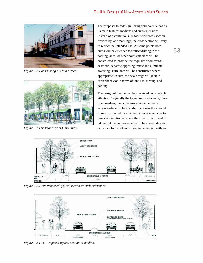
Flexible Design of New Jersey’s Main Streets
53
The proposal to redesign Springfield Avenue has asits main features medians and curb extensions.Instead of a continuous 50-foot wide cross sectiondivided by lane markings, the cross section will varyto reflect the intended use. At some points bothcurbs will be extended to restrict driving in theparking lanes. At other points medians will beconstructed to provide the requisite “boulevard”aesthetic, separate opposing traffic and eliminateswerving. Turn lanes will be constructed whereappropriate. In sum, the new design will dictatedriver behavior in terms of lane use, turning, andparking.
The design of the median has received considerableattention. Originally the town proposed a wide, tree-lined median; then concerns about emergencyaccess surfaced. The specific issue was the amountof room provided for emergency service vehicles topass cars and trucks where the street is narrowed to34 feet (at the curb extensions). The current designcalls for a four-foot wide mountable median with no
Figure 3.2.1.8: Existing at Ohio Street.
Figure 3.2.1.9: Proposed at Ohio Street.
Figure 3.2.1.10: Proposed typical section at curb extensions.
Figure 3.2.1.11: Proposed typical section at median.

Chapter 3
54
trees. This provides 15 feet curb to curb in eachdirection—plus the mountable median. If a car isstalled or illegally parked, the fire engine simplymounts the median.
Other Design SolutionsSidewalks & Alleys
Outside of the curb-to-curb changes, the redesignincludes numerous other streetscape improvements.Primary is a series of beautified alleyways leading to“shared” parking lots in the rear of buildings. Thesewill require the coordination of the merchantsassociation and property owners, as they lie outsidethe town’s right-of-way. Additionally there havebeen discussions about narrowing some drivewaysas a means of increasing on-street parking andallowing more planting area.
The clear sidewalk width is presently four to sevenfeet, depending on pavement width and obstacles.In the proposed redesign, the curb-to-buildingdistance will generally remain the same but grow to18 feet at the curb extensions. It is envisioned thatstreet furniture will be consolidated so that the clearwalking zone will be wider and more consistent.
Crossings
In terms of street crossings, pedestrians arecurrently assisted only by traffic signals, clearcorner zones, and “Yield to Pedestrians in Cross-walk” signs at the uncontrolled crosswalks. Fewdrivers actually yield, and pedestrians have to waitfor a gap in traffic during a red light, before attempt-ing to cross. The proposed changes will improvethis condition by:
! Reducing pedestrian crossing distanceby 16 feet at the curb extensions, and
! Providing a refuge area for pedestriansat the medians so they can cross onedirection of traffic at a time.
Even though the four-foot wide median meets theminimum DOT standard, it is less than the generallyrecommended six feet for pedestrian refuge islands.
Intersections
In redesigning the intersections, the corner radii willbe increased to provide for larger turning vehicles.Yet with the curb extensions, the overall crossingdistance will be reduced.
Table 3.2.1.2: Comparison of lane and streetwidths.
Table 3.2.1.3: Comparison of marked and physicaldimensions.
Condition Lane StreetWidths (ft) Width (ft)
Former 10+11+11+10+8 50
Present 8+12+10+12+8 50
Proposed 12+10+12 34at curbextensions
Proposed 8+12+3+4+3+12+8 50at median
Proposed at 12+3+4+3+12 34median &curbextensions
Condition Lane Widths (ft)
Marked at median & 8+12+3+4+3+12+8parking lane
Possible at median & 6+17+4+17+6parked car
Marked at median & 12+3+4+3+12curb extensions
Possible at median & 15+4+15curb extensions
Marked median width 10
Actual raised median 4width

Flexible Design of New Jersey’s Main Streets
55
The stop lines at the signalized intersections will beset back from the crosswalks and aligned with streettrees or street furniture. This coordination will givedrivers a visual cue as to where to stop and hope-fully keep them from blocking crosswalks (andpedestrian ramps). At the diagonal intersections, thestop lines will be aligned perpendicular to the travellanes. This will effectively widen the crosswalks andreduce the crossing distances.
Performance FlexibilityThe posted speed limit on Springfield Avenue is 35mph; the town has proposed changing this to 25mph. Although a design speed has not yet beenestablished, it is expected that the redesigned roadwill self-enforce the posted speed.
Counterintuitive as it may seem, the proposedreconfiguration of Springfield Avenue may actuallyimprove level of service (LOS) at certain intersec-tions. A traffic analysis showed this could beachieved by re-timing the signals to 90-secondcycles, removing one of the ten signals, andrestricting turns at another intersection. Theproposed reconfiguration will cause LOS for thearterial as a whole, end-to-end, to suffer. Yet with theexpected de-designation of Route 124, state DOTshould have no objections.
Figure 3.2.1.12: Existingnarrow sidewalk.
Figure 3.2.1.13: Existing uncontrolled crosswalk.
Figure 3.2.1.14: Proposed Yale Street intersection.
Figure 3.2.1.15: Proposed Prospect Streetintersection.
Figure 3.2.1.16: Proposed Park Avenueintersection.

Chapter 3
56
Institutional Collaboration
The manner in which DOT worked with localgovernment to change the roadway from four tothree travel lanes was exemplary. DOT installedtemporary markings and placed cones at strategiclocations to test the proposed design. It performedtraffic counts and assessed level of service. Findingthe design was satisfactory, the state made thechanges permanent.
In January 2000 the town approached DOT with itsplan to further redesign the street. At first the planappeared too radical for DOT, particularly since thestreet is currently on the National Highway System.But when DOT realized that the state route designa-tion ended at the city line, its attitude changed. Tothe east of Maplewood (Irvington) the road be-comes a county route. Hence, the state came to viewthe de-designation not as breaking a chain, butmerely removing the last link. The de-designation isforthcoming. With de-designation, it is expected thatRoute 124 will be taken off the National HighwaySystem.
Public Response
In preparing the Economic Development Plan, theTownship and consultant performed substantialcommunity outreach. Three detailed surveys weretaken of businesses, consumers and residents,along with a series of public meetings and worksessions. Specifically the Economic DevelopmentCommission worked with the Township Committee,
the Springfield Avenue Partnership, and the HiltonNeighborhood Association. The outreach confirmedthat stakeholders were concerned with, among otherthings:
! Adequacy of street lighting,
! Speed of traffic,
! Timing of traffic lights, and
! Difficulty in crossing the street.
As of now the town officials are leading the designprocess, having hired planners, landscape architectsand engineers. They are negotiating with the stateand are selling the project within their own commu-nity. The major sticking point is the cost of repav-ing—$400,000 every ten years. The town’s entirecapital budget is only $1.5 million annually and toassume this cost will be a burden. In addition theproject construction costs are estimated to the $7.5million. The town is floating bonds to pay for theproject. It has also proposed that the countymaintain the signal equipment, even though themunicipality will control the timing.
Construction on phase I (from the western townboundary to Yale Street) is expected to commencesoon. It is hoped that the project can be completedby 2003.
[All sketches and plans courtesy Zion & Breen Associates—Site Planners & Landscape Architects. All traffic datacourtesy Orth-Rodgers Associates Transportation Engineers& Planners.]
Table 3.2.1.4: Springfield Avenue performance.
Table 3.2.1.5: Project status summary.
Project Status Planning Phase
City Population 22,000
Adjacent Land Use Commercial, Institutional,Park
Road Classification Urban Principal Arterial
Road Ownership To Be De-designated ByState
Design Exception Required No
Project Cost $7.5 Million
Economic Data Enhanced Road Expected ToIncrease Tax Revenues
Existing Proposed(1999) (2004)
ADT 15,000— 16,200—20,000 21,500
Intersection LOS B-F B-D
Arterial LOS C C-D
Signal Cycle (sec) 120 90

Flexible Design of New Jersey’s Main Streets
57
Table 3.2.1.6: Data summary for Springfield Avenue, Maplewood, New Jersey.
Element Before After
Number Of Lanes 4 3
Lane Width + offset, feet 10-11 10-15
Shoulder Width or Cycle Lane, feet — —
Street width, feet 50 34-50
On-street Parking One side Both sides
On-street Parking width, feet 8 8
Sidewalk Width, feet 4-7 4-18
Posted Speed, mph 35 35
85th Percentile or Design Speed, mph — —
Vehicle Volume, ADT (DY-2004) 15,000-20,000 16,200-21,500
Level of Service B-F (intersection) C (arterial)B-D (intersection) C-D (arterial)
Crash Data, reportable — —
Truck Volume — —
Pedestrian Volume — —
Bike Volume — —
Corner Radii, feet 15-25 25 (overall intersectionarea decreases with curbextensions)
Stopping Sight Distance, feet — Increased with curbextensions

Chapter 3
58
3.2.2 Plainfield, SouthAvenue (NJ 28)
Route 28 parallels the New Jersey TransitRaritan Valley Line and serves as the mainstreet for a series of towns along this
valley. While many of these towns (Westfield,Plainfield, Cranford) have distinct pedestrian-friendly downtowns, the Netherwood section ofPlainfield lacks one. In recent years, much of thebusiness activity has been automobile-oriented.Seeking to change this, the City of Plainfieldrecently obtained funding to create a sense of placeand identifiable center around the HistoricNetherwood Train Station.
Geometric FlexibilityThe South Avenue project is seven blocks and 0.8mile long. It is classified as an Urban PrincipalArterial but is not on the National Highway System.Even though it is designated a state route, Route 28is not maintained by the state through Plainfield.This allows a certain amount of design flexibility, forthe roadway need not conform to DOT’s RoadwayDesign Manual.
South Avenue before the reconstruction variedbetween 40 and 41 feet wide with two 12 to 13-foottravel lanes and two eight-foot parking lanes.Originally the town proposed to narrow the travel
Figure 3.2.2.1: South Avenue construction.
Figure 3.2.2.2: Area map of Plainfield, New Jersey.
Figure 3.2.2.3: Project plan.

Flexible Design of New Jersey’s Main Streets
59
lanes to nine feet and install medians and curbextensions. Had this street been maintained by thestate, the project manager at DOT stated that helikely would have insisted on 12-foot travel lanes.Instead, travel lanes were constructed to a compro-mise width of 11 feet
At Old South Avenue, an arcing street connected atboth ends to South Avenue, the South Avenuecross section was narrowed to 30 feet wide. Thiswas accomplished by eliminating the parking laneand enlarging the park. Along the remainder of theproject on-street parking is now allowed in mostareas.
Other Design SolutionsCurb Extensions
Curb extensions were part of the original proposaland were retained in the final design. The extensionsvisually narrow the road, define parking bays, andact as a gateway to the town. They are eight feetwide, match the width of the parking lane, and alignwith the mid-block crosswalks. Trees and streetfurniture are planned for the extensions. The DOTproject manager speculates that had this route beenbuilt to state standards, there would likely havebeen neither curb extensions nor on-street parking.
The curb extensions have been hit a few times bypassing motorists. Whether this was due to drivererror or design of the extensions themselves isunclear. The issue has become somewhat politicizedand the design itself has been questioned by the
opposition. The extensions are eight-feet wide—thewidth of the parking lane, yet slightly wider than aparked car. As a safety measure the City installededge lines before each extension. It is expected thatwith street furniture, street lamps, and more visiblecrosswalks, drivers will become more aware of thegeometry.
Another issue with curb extensions is drainage.Because non-linear curbs have a tendency to blockstormwater runoff, drainage has to be handled withcare. In some locations catch basins were added,and in others a reverse slope was designed into theroadway to direct water around the extensions.
Crosswalks
As this street parallels the train tracks, there is littlecross traffic and some blocks stretch up to 700 feet.One of the primary purposes of the project was toencourage pedestrian traffic in the area. Because ofthe futility of expecting pedestrians to walk out oftheir way to cross the narrowed street, especially ina commercial environment, uncontrolled mid-blockcrosswalks were added. The crosswalks are of brick
Table 3.2.2.1: Cross-section comparison.
Figure 3.2.2.4: Before at Train Station Plaza.
Figure 3.2.2.5: After at Train Station Plaza.
LANE WIDTHS (ft)Travel Parking Total
Former 12-13 8 40-41
Town Proposal 9 8 34
NJDOT Probable 12 8 40
AASHTO Minimum 10 8 36
As built 11 8 38

Chapter 3
60
paving stones, similar to the sidewalks and plaza.While the pavers do not by themselves calm traffic,their frequency and coordination with bulb-outsaccentuate the pedestrian-friendly nature of thestreet.
The legal status of mid-block crosswalks in NewJersey is not entirely clear. According to State
Statute:
In the case of totally self-contained streetsunder municipal jurisdiction which haveno direct connection with any street inany other municipality… the municipal-ity… may, by ordinance or resolution, asappropriate, without the approval of theCommissioner of Transportation, desig-nate parking restrictions, no passing
Figure 3.2.2.6: Typical plan.
Figure 3.2.2.9: Curb extension poking out betweenparked cars.
Figure 3.2.2.7: Typical curb extensions.
Figure 3.2.2.8: Inlet at curb extension. Figure 3.2.2.10: Edge line before curb extension.

Flexible Design of New Jersey’s Main Streets
61
zones, mid-block crosswalks and cross-walks at intersections… [emphasisadded]1
While South Avenue clearly connects to roadsoutside Plainfield, the DOT project manager did notobject to the mid-block crosswalks because thestreet is owned and maintained by the city and istechnically not a state highway.
At one intersection, crosswalks are offset 22-30 feetfrom the sidewalk on the side street. This is done atthe intersection with Belvidere Avenue to allow aperpendicular alignment between the curb cut andcrosswalk. While this is beneficial for those inwheelchairs, it is problematic for the visuallyimpaired traveler. When the crosswalk is not anatural extension of the sidewalk, it is a challenge tofind it with a cane. It will be instructive to observewhether pedestrians simply ignore the crosswalkand cross following their desire lines.
Medians
The originally proposed medians were not includedin the final design for two reasons. Using a standardSingle Unit truck (SU) turning template, it waspredicted that trucks would mount the median atprecisely the point where pedestrians would wait tocross the street. The other reason is that themedians would be only two-feet wide. This isnarrower than the DOT standard of four feet, andmuch less than the six feet required to protect aperson pushing a baby stroller or bicycle. This is agood example of balancing the many uses of astreet.
Corner Radii
At the intersection with Belvidere Avenue, thecombination of lane width, corner radius, and curbextension creates a condition where the SU designvehicle turning onto South Avenue will cross thecenterline. This is inconsistent with standardpractice. At this intersection, though, traffic onSouth Avenue is free flowing with no stop sign orsignal control, so the DOT project manager con-cluded that traffic will not queue up, therebyblocking the turning path. He also concluded thattrucks turning onto South Avenue will be able tofind appropriate gaps in traffic, and travel speedswill be slow enough to keep encroachment into theopposing lane from causing a hazard.
1 Title 39: Motor Vehicles and Traffic Regulation, Section 39:4-8.b.
Figure 3.2.2.11: Mid-block crosswalk. Figure 3.2.2.13: Originally proposed medians.
Figure 3.2.2.12: Belvidere Avenue intersection.
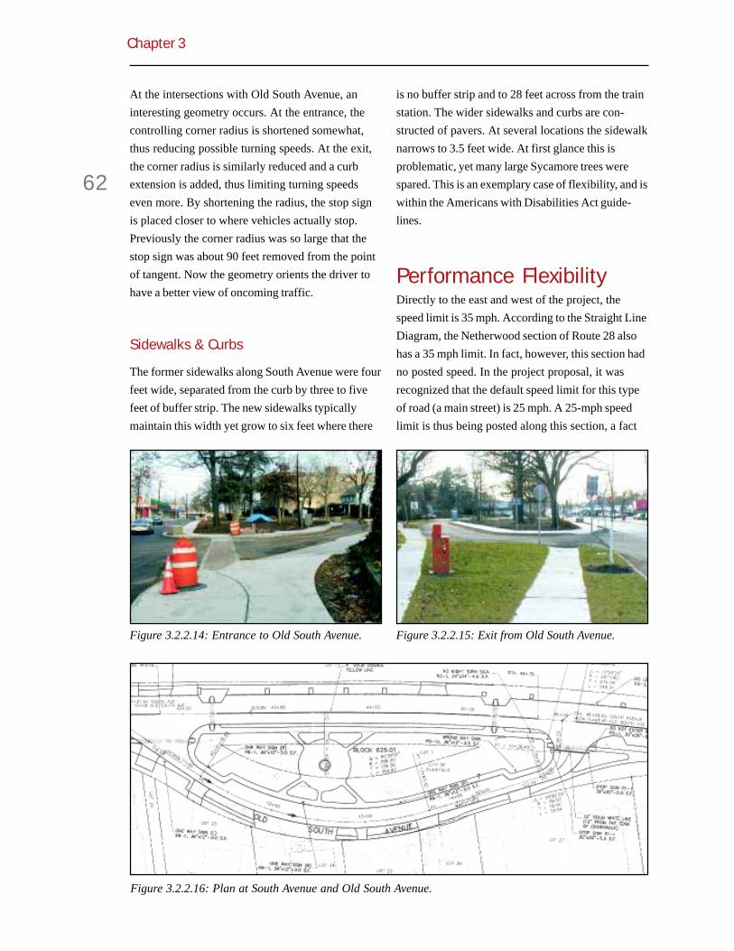
Chapter 3
62
At the intersections with Old South Avenue, aninteresting geometry occurs. At the entrance, thecontrolling corner radius is shortened somewhat,thus reducing possible turning speeds. At the exit,the corner radius is similarly reduced and a curbextension is added, thus limiting turning speedseven more. By shortening the radius, the stop signis placed closer to where vehicles actually stop.Previously the corner radius was so large that thestop sign was about 90 feet removed from the pointof tangent. Now the geometry orients the driver tohave a better view of oncoming traffic.
Sidewalks & Curbs
The former sidewalks along South Avenue were fourfeet wide, separated from the curb by three to fivefeet of buffer strip. The new sidewalks typicallymaintain this width yet grow to six feet where there
is no buffer strip and to 28 feet across from the trainstation. The wider sidewalks and curbs are con-structed of pavers. At several locations the sidewalknarrows to 3.5 feet wide. At first glance this isproblematic, yet many large Sycamore trees werespared. This is an exemplary case of flexibility, and iswithin the Americans with Disabilities Act guide-lines.
Performance FlexibilityDirectly to the east and west of the project, thespeed limit is 35 mph. According to the Straight LineDiagram, the Netherwood section of Route 28 alsohas a 35 mph limit. In fact, however, this section hadno posted speed. In the project proposal, it wasrecognized that the default speed limit for this typeof road (a main street) is 25 mph. A 25-mph speedlimit is thus being posted along this section, a fact
Figure 3.2.2.16: Plan at South Avenue and Old South Avenue.
Figure 3.2.2.14: Entrance to Old South Avenue. Figure 3.2.2.15: Exit from Old South Avenue.

Flexible Design of New Jersey’s Main Streets
63
that made the DOT project manager comfortablewith progressive design features such as curbextensions, narrower lanes, reduced corner radii.These were viewed as consistent with the expectedtravel speeds on the road.
Volumes
As this is not officially a state route and no trafficcontrol was altered, no traffic analysis was per-formed. Volumes in 1998 were about 13,000 per dayaccording to the Straight Line Diagram.
Institutional Collaboration
The project cost about $1.5 million—half a millionfrom federal T-21 Enhancement funds, and half amillion from the New Jersey Transportation TrustFund. DOT distributes these funds and so has aninterest in the project. While DOT has taken no
position on performance of the street, it has had aresponsibility to see that the design meets standardengineering guidelines.
The Netherwood Train Station was listed in theNational Register of Historic Places in 1984. In 1993the train station was selected by New Jersey Transit(NJT) as a demonstration project to show how arenovated station could serve as a catalyst for theimprovement of the surrounding community. Overone million dollars was spent by NJT in remodelingthe station, and the street improvement work is seenas a happy complement. There has been a subse-quent agreement between the City, NJT, and theFriends of Sleepy Hollow (FOSH) to maintain thestation.
In the City of Plainfield’s Master Plan, SouthAvenue is to receive special planning consideration.Plainfield is a designated Center in the NJ State Plan.The area has been designated a NeighborhoodEmpowerment Zone by the state, and it is a NJRA
Figure 3.2.2.17: Wide sidewalk at Commercial. Figure 3.2.2.19: Modular curbs.
Figure 3.2.2.18: Sidewalk at tree. Figure 3.2.2.20: Curb detail.

Chapter 3
64
Urban Coordinating Council designated community.These designations have given the town priority forstate funding.
Public Outreach and Response
Before the start of the project there was an activestreetscape improvement effort by the local commu-nity. Flower planters were placed at the station,historic lights were installed, restaurants heldspecial events, and businesses improved theirfaçades.
Public reaction to the project is positive with FOSH,the local neighborhood association, and thePlainwood Square Business Association fully andpublicly supporting the project. These organizationshad been involved since the early planning of theproject.
The local newspapers chronicled the project andeditorialized in favor of the project and its intent.There was some concern due to minor constructionzone related mishaps; these incidents have abatedas the project nears completion. Traffic has slowedvisibly in the area and is expected to slow more oncethe project is complete. With the finished product,positive public sentiment is expected to grow asadditional fruits of the work are realized. Theseinclude economic development due to increasedfoot traffic throughout the corridor.
The project received a 1997 New Jersey PlanningOfficials’ Planning Achievement Award.
Figure 3.2.2.21: Former train station.
Figure 3.2.2.22: Renovated train station.Table 3.2.2.2: Project status summary.
Project Status 2000 (completed)
City Population 50,000
Adjacent Land Use Commercial, Transit,Park, Residential
Road Classification Urban Principal Arterial
Road Ownership City
Design Exception Required No
Project Cost $1.5 million
Economic Data —

Flexible Design of New Jersey’s Main Streets
65
Table 3.2.2.3: Data summary for South Avenue, Plainfield, New Jersey.
Element Before After
Number Of Lanes 2-4 2
Lane Width + offset, feet 12-13 11
Shoulder Width or Cycle Lane, feet 8 8
Street width, feet 40-41 38
On-street Parking some increased
On-street Parking width, feet 8 8
Sidewalk Width, feet 4 3.5-28
Posted Speed, mph 25 25
85th Percentile or Design Speed, mph — —
Vehicle Volume, ADT (DY-2004) 13,000 —
Level of Service — —
Crash Data, reportable — —
Truck Volume — —
Pedestrian Volume — —
Bike Volume — —
Corner Radii, feet varied 30
Stopping Sight Distance, feet — —

Chapter 3
66
3.2.3 South Orange, SouthOrange Avenue (CR 510)
South Orange is a suburban town of about16,500 people in northern New Jersey on theMorristown New Jersey Transit line. Over
the years its main street, South Orange Avenue(County Route 510), had grown into a four-lanethoroughfare where too many cars whizzed past toofew active storefronts. The town felt that SouthOrange Avenue was cutting the village in half, andresolved to do something about it.
In the mid-1990s, the commuter rail station andenvirons were redeveloped. Between 1997 and 2000the roadway was shrunk to one lane in eachdirection with center left-turn lanes. Sidewalks wereexpanded, intersections narrowed, and medians andislands installed. As a result, vehicular speeds fell,the pedestrian environment improved, and busi-nesses became more successful.
Geometric FlexibilityPrior to its reconstruction, South Orange Avenuehad a constant 60-foot cross section with two travellanes and one parking lane in each direction. Thecounty and city agreed to narrow the street by
Figure 3.2.3.1 South Orange Avenue.
Figure 3.2.3.2 Area map.
Figure 3.2.3.3 Downtown area plan. Figure 3.2.3.5 After at Valley Street.
Figure 3.2.3.4 Before at Valley Street.

Flexible Design of New Jersey’s Main Streets
67
removing one lane in each direction, adding centerturn lanes, expanding a center island, and wideningthe travel lanes so cars could pass those parking ordouble parked. The reconstructed road is generally54-56 feet in width with 12-15-foot wide travel lanes.Eight-foot parking lanes framed by curb extensionsremain on both sides. At intersections the lanesnarrow to allow for turn lanes. In sum, the road nowbetter reflects the travel patterns and land use of thearea.
To the west is a rather steep grade from whichdrivers gain momentum just as they are entering thedowntown area. To counter this, a raised medianwas installed which narrows the roadway andremoves the opportunity to pass slower drivers. Incase of errant driving, the curbs are fully mountable.Even so, the median is planted, and the effect isclearly a gateway into town.
Figure 3.2.3.6 Before at Academy Street. Figure 3.2.3.7 After at Academy Street.
Table 3.2.3.1: Lanes before and after.
Figure 3.2.3.8 Plan at Vose Avenue.
Figure 3.2.3.9 Plan at Village Plaza.
Curb-to-Condition Lanes Lane width (ft) curb (ft)
Former P+T+T+T+T+P 8+11+11+11+11+8 60
New at Valley Street/Scotland Road P+T+LT+T+RT 8+13+11+12+12 56
New at Sloan Street P+T+LT+T+P 8+15+11+12+8 54
New at Vose Avenue P+T+T+P+RT 8+16+15+15 54
New at Village Plaza T+T 17+17 34
New at Mid-Block Crosswalks T+T 15+15 30

Chapter 3
68
Reconstruction plans for South Orange Avenue didnot include marked cycle lanes since the number ofturning movements precluded continuous lanes.However, the generally 15-foot wide lanes are toshared-use standards, and the travel speeds aresuch that cyclists can merge with vehicles.
Other Design SolutionsIntersections and Mid-Block Crosswalks
The crossing distance for pedestrians at intersec-tions has been reduced via curb extensions and thenarrowed cross section. At the intersection withVose Avenue, the widened sidewalk and curbextension reduce the crossing distance for pedestri-ans by 14 feet. At the intersection with Village Plaza,curb extensions on both sides reduce the crossingdistance by approximately 25 feet. At the easternend of the main downtown area where AcademyStreet and Irvington merge into South OrangeAvenue, an existing center island was significantlyexpanded, which reduced the width of the travelwayfrom 60 to 30 feet. Crosswalks leading to and fromthe island on both sides were also reoriented tobetter reflect pedestrian design lines. For theuncontrolled mid-block crosswalks, a new Cityordinance was required as per state statute.
The new mid-block crosswalks give people more“sanctioned” options to cross the street. As these
are away from the signals and turning conflicts ofintersections, they may be safer and impose lessdelay on pedestrians. The fact that the crosswalksare brick paved and coordinated with curb exten-sions and vertical streetscape elements means thatdrivers are more apt to yield to crossing pedestrians,as drivers are legally required to do. More pedestri-ans crossing has the effect of further slowing traffic.In a way, pedestrians, seen as “flow interrupters” interms of vehicle LOS, are doing just that. The resultis organic traffic calming.
At the intersection with Valley Street, there is abutton-actuated seven-second leading pedestrianinterval in one direction. This provides pedestriansan opportunity to cross ahead of turning vehicles,but the button is not in an obvious location. The LPIis not automatic, for the county did not want tosacrifice vehicular level-of-service. Nevertheless,drivers were observed generally yielding to pedestri-ans, and LOS is compromised anyway.
Figure 3.2.3.10 Plan at Valley Street/ScotlandRoad.
Figure 3.2.3.11 Edge lines where street width isreduced in segments.
Figure 3.2.3.12 Raised median as a gateway intotown.

Flexible Design of New Jersey’s Main Streets
69
Figure 3.2.3.15 Before crosswalk at AcademeyStreet.
Figure 3.2.3.16 After crosswalk with islandexpansion at Academey Street.
Figure 3.2.3.17 Curb extension narrows mid-blockcrossing.
Figure 3.2.3.18 Curb extension with bollards.
Figure 3.2.3.13 Center island reconstruction atIrvington Avenue/Academey Street.
Figure 3.2.3.14 Pedestrian push button.
Table 3.2.3.2 Change in crossing distance.
Change incrossing
Former Present distanceCrossing (ft) (ft) (ft)
Academy Street 60 30 -30Village Plaza 62 37 -25Mid-Block 60 38 -22Vose Avenue 60 46 -14Sloan 60 54 -6Valley Street 67 63 -4

Chapter 3
70
Stop lines were added at all controlled intersections.They are placed where the designer wants the driverto stop, not necessary parallel to the crosswalk norfour feet in front, as in the MUTCD. Stop linelocations are based on turning radii of trucks,ensuring they will have ample room to turn. Thegreater setback also allows cyclists to queue aheadof waiting vehicles.
With the curb extensions, seven parking spaceswere lost. One bus stop was moved from a turn lanelocation to mid-block, which eliminated three parkingspaces but improved travel flow. Initially thisseemed to be a concern for local merchants. Yet,since there has been an obvious increase ofpedestrian activity, the trade-off is now seen asworthwhile.
Brick Sidewalks & Crosswalks
Several crosswalks have been made of brick toemphasize the pedestrian environment and furtherdifferentiating the crossing locations. The paversare similar to those used on the sidewalks, alleys,side streets, and around the train station. Previ-ously-closed alleys and short cuts have beenopened to provide shorter links to the various storesand offices throughout town. Numerous streetscapeelements were added such as bollards with chains,pedestrian-scaled streetlights, benches, and plantersand planting beds. These amenities take advantageof changes in elevation to yield a more interestingdesign. Lighting was improved to enhance security.The result is a unified whole where the driver can beseen as a guest through town.
Figure 3.2.3.19: Before sidewalk. Figure 3.2.3.20: After sidewalk.
Figure 3.2.3.21: Crosswalks corrdinated withalleys.
Figure 3.2.3.22: Improved aesthetics and lightingin alleys.

Flexible Design of New Jersey’s Main Streets
71
Performance FlexibilityThe speed limit through town remains at 25 mph.While no speed data have been collected, interviewsreveal that people perceive cars going much slowersince the reconstruction.
When the town began planning the redesign, thefollowing point was raised: Although the roadserves as a major arterial between Newark and SouthMountain, it narrows to two lanes on either side oftown. It was argued that the section throughdowntown South Orange could be likewise reducedto two lanes. Although the county preferred ahigher LOS, the town of South Orange was contentto reach LOS D with the new design, which wasconsidered acceptable for a downtown.
Institutional Collaboration
South Orange Avenue is a county route, and thework was coordinated with Essex County. Thecounty engineer at the time was opposed to theproject but the county executive was in favor. As acompromise, the town passed a resolution pledgingto return the street to its previous condition if theproject failed in some respect. The resolution,however, never defined objective criteria of successor failure. As such it somewhat favored the town.
The greatest concern for the county besides LOSwas maintenance. The county worried that plowing,for example, would become much more complicatedand expensive. So the town and county eventuallyagreed to split responsibilities; the town plows theparking bays and maintains other pedestrianfeatures and the county plows the travel lanes.
In designing the project, the town actively con-sulted ADA guidelines and worked with localdisabled activists. As a result, pedestrian facilitiesare as ADA-friendly as possible.
Public Response
The improvements to South Orange Avenue werespearheaded by a group of local merchants andresidents known as “Main Street South Orange.” Incollaboration with the town, the group commis-sioned a study and laid plans for calming traffic andimproving pedestrian amenities in order to attractpeople to downtown. To finance the $1.6 millionproject, including all streetscape elements, the cityissued bonds.
The renovation of the shops and plaza at the trainstation was financed with a Community Develop-ment Block grant from HUD. It went a long waytoward convincing citizens and business people to
Figure 3.2.3.23: Cover of Engineering News-Record, January 1998.
Figure 3.2.3.24: Inside Engineering News-Record,January 1998.
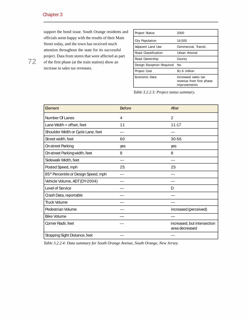
Chapter 3
72
support the bond issue. South Orange residents andofficials seem happy with the results of their MainStreet today, and the town has received muchattention throughout the state for its successfulproject. Data from stores that were affected as partof the first phase (at the train station) show anincrease in sales tax revenues.
Table 3.2.2.3: Project status summary.
Table 3.2.2.4: Data summary for South Orange Avenue, South Orange, New Jersey.
Project Status 2000
City Population 16,500
Adjacent Land Use Commercial, Transit,
Road Classification Urban Arterial
Road Ownership County
Design Exception Required No
Project Cost $1.6 million
Economic Data Increased sales taxrevenue from first phaseimprovements
Element Before After
Number Of Lanes 4 2
Lane Width + offset, feet 11 11-17
Shoulder Width or Cycle Lane, feet — —
Street width, feet 60 30-56
On-street Parking yes yes
On-street Parking width, feet 8 8
Sidewalk Width, feet — —
Posted Speed, mph 25 25
85th Percentile or Design Speed, mph — —
Vehicle Volume, ADT (DY-2004) — —
Level of Service — D
Crash Data, reportable — —
Truck Volume — —
Pedestrian Volume — increased (perceived)
Bike Volume — —
Corner Radii, feet — increased, but intersectionarea decreased
Stopping Sight Distance, feet — —

Flexible Design of New Jersey’s Main Streets
73
3.2.4 WashingtonTownship, Town Center (NJ33 and US 130)
(This case study was prepared by Charles Carmaltand is far more detailed and process-oriented thanthe other case studies. As such, it provides adifferent perspective on the opportunities andobstacles inherent in context-sensitive design.)
Washington Township (pop. 8,700) islocated in Mercer County at thegeographic center of New Jersey near
the intersection of the New Jersey Turnpike andInterstate 195. Because of its central location,important transportation routes have long crossedthe township, linking northern and southern NewJersey (and linking New York and New England withPhiladelphia, Washington and the South).
The historic village of Robbinsville evolved at theintersection of US 130 (the Bordentown-AmboyTurnpike), and NJ 33 (Nottingham Way), roads thatwere state arteries long before there was a statehighway department. US 130 had been laid outduring the early nineteenth century to servestagecoaches that connected Philadelphia and NewYork City. During the 1930s it had been recon-
structed as a divided highway and had served as themajor north-south highway through New Jerseyprior to the construction of the New Jersey Turn-pike. Unlike other towns located along the highway,such as Cranbury, Hightstown and Yardville, abypass had never been constructed aroundRobbinsville, and as a result the divided highwayhad severed both the village and the township.
Since construction of the New Jersey Turnpike,Route 130’s function has become more limited,primarily serving regional rather than statewide andnational travel needs. Likewise, since constructionof parallel I-195, NJ 33 serves more localized travelneeds, with most trips having at least one trip end ineither Washington Township or a nearby municipal-ity.
The two highways passing through Robbinsvilleprovide the village, and the planned Town Center,with excellent accessibility to the rest of the region.Figure 3.2.4.1: Area map.
Figure 3.2.4.2: County Route 526.
Figure 3.2.4.3: State Route 130.

Chapter 3
74
At the same time, the fact that Route 33 no longerserve strategic national and statewide travel needsprovides the opportunity for creative redesigns.
Plans for the Town Center
Despite its central location, the township experi-enced only limited development prior to 1985. Themajority of its land was still in farming. Two historicvillages, Robbinsville and Windsor, were theprincipal settlements. People moved to WashingtonTownship because of its rural character, and theprotection of that rural character was an importantcommunity goal.
By 1985, it had become evident that the townshiplay in the path of growth. That year, WashingtonTownship officials decided that they would seek tomanage growth by developing a master plan andzoning ordinance that concentrated development ina new town center. The town center would becreated by expanding the traditional village center ofRobbinsville. Officials would also seek to limitdevelopment in the remainder of the township.
The passage of state statutes such as the Freshwa-ter Wetlands Protection Act and the State PlanningAct substantially changed how development wouldbe planned and regulated in New Jersey andWashington Township. The township committeeultimately adopted the Town Center Ordinance in
1997, which created planning and design regulationsgoverning development within the Town CenterZone, and which established strict controls overhow development within the center would occur.
Washington Township wants its Town Center to bea walkable place with a diversity of land uses andhousing types. The 450-acre development shouldfunction as a town center to the rest of the town-ship. It should be seamlessly woven into the landuse fabric of the 20 square mile township.
Washington Township has used TraditionalNeighborhood Design (TND) principles to design itsTown Center. Because of the mixture of land usesproposed, most homes will be within walkingdistance of a wide range of community commercialuses. A commercial center will provide approxi-mately 250,000 square feet of commercial space intwo- and three-story buildings. Additional commer-cial space will be constructed along NJ 33, which theTown Center plan proposes will become a “MainStreet.”
As a result of the synergy between land uses, andtheir location in the plan, the number of external tripsby residents should be reduced, especially onweekends and other non-peak travel periods. At thesame time, the accessibility provided by the regionalroadways that penetrate the Town Center will ensurethat businesses are able to market themselves tosurrounding communities, thereby attractingexternal trips.
Figure 3.2.4.4: Mixed-use plan. Figure 3.2.4.5: Traditional Neighborhood Design.
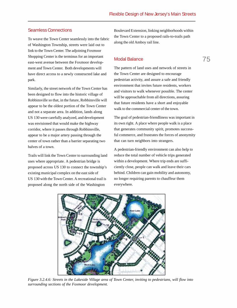
Flexible Design of New Jersey’s Main Streets
75
Seamless Connections
To weave the Town Center seamlessly into the fabricof Washington Township, streets were laid out tolink to the Town Center. The adjoining FoxmoorShopping Center is the terminus for an importanteast-west avenue between the Foxmoor develop-ment and Town Center. Both developments willhave direct access to a newly constructed lake andpark.
Similarly, the street network of the Town Center hasbeen designed to flow into the historic village ofRobbinsville so that, in the future, Robbinsville willappear to be the oldest portion of the Town Centerand not a separate area. In addition, lands alongUS 130 were carefully analyzed, and developmentwas envisioned that would make the highwaycorridor, where it passes through Robbinsville,appear to be a major artery passing through thecenter of town rather than a barrier separating twohalves of a town.
Trails will link the Town Center to surrounding landuses where appropriate. A pedestrian bridge isproposed across US 130 to connect the township’sexisting municipal complex on the east side ofUS 130 with the Town Center. A recreational trail isproposed along the north side of the Washington
Boulevard Extension, linking neighborhoods withinthe Town Center to a proposed rails-to-trails pathalong the old Amboy rail line.
Modal Balance
The pattern of land uses and network of streets inthe Town Center are designed to encouragepedestrian activity, and assure a safe and friendlyenvironment that invites future residents, workersand visitors to walk whenever possible. The centerwill be approachable from all directions, assuringthat future residents have a short and enjoyablewalk to the commercial center of the town.
The goal of pedestrian-friendliness was important inits own right. A place where people walk is a placethat generates community spirit, promotes success-ful commerce, and frustrates the forces of anonymitythat can turn neighbors into strangers.
A pedestrian-friendly environment can also help toreduce the total number of vehicle trips generatedwithin a development. Where trip ends are suffi-ciently close, people can walk and leave their carsbehind. Children can gain mobility and autonomy,no longer requiring parents to chauffeur themeverywhere.
Figure 3.2.4.6: Streets in the Lakeside Village area of Town Center, inviting to pedestrians, will flow intosurrounding sections of the Foxmoor development.

Chapter 3
76
Although the needs of pedestrians were consideredfirst, the needs of all travel modes had to bebalanced in the Town Center. The integratednetwork of streets will allow auto traffic to floweasily through the Town Center. The concentrationof residences, jobs, and shopping destinationsshould be sufficient to support transit services tomajor employment centers including downtownTrenton, the Route 1 corridor, and Philadelphia andNew York.
Hierarchy of Streets
To accomplish its other objectives, the townshipsoon recognized that it had to develop a newroadway hierarchy sensitive to the different landuses and travel needs served. For each roadway, theappropriate function had to be defined and thecompeting needs of motor vehicles and other usersbalanced.
A central element of the Town Center Plan was a“Street Regulating Plan.” This plan specified thealignment of each street, the function of each streetwithin the hierarchical network, and the typicalcross-section of each class of street. Any change inthe plan would constitute a Master Plan change anda zoning variance.
All properties will be served by rear or side alleysthat provide access to garages and are used bygarbage trucks and other service vehicles. Byconcentrating vehicular access function in alleys,the street frontage of properties will be uninter-rupted by driveways, building setbacks can bereduced, and more on-street parking can be sup-plied. This will allow all streets to function moreefficiently, both for motor vehicles and pedestrians.The use of alleys assures that individual drivewayswill not be constructed along the major roadways.
Most of the streets within the Town Center will beresidential streets or residential lanes with littlethrough traffic; the majority of housing units willfront on these streets. Because residential streetsand lanes in the Town Center will have low trafficvolumes, and will not have to serve turning move-ments into driveways, their widths can be reducedcompared to typical subdivision streets, and theamounts of rights-of-way devoted to street treesand sidewalks increased.
Figure 3.2.4.7: Pedestrian circulation plan.
Figure 3.2.4.8: Pedestrian-friendly site plan.

Flexible Design of New Jersey’s Main Streets
77
A limited number of avenues are proposed in theStreet Regulating Plan to serve heavier trafficvolumes. Some of these avenues will allow regionaltrips to flow around the commercial center, reducingthe amount of traffic that must be accommodated onMain Street. Other avenues will serve as majorspines to the Town Center, drawing both pedestri-ans and motor vehicles from the periphery into thecommercial center. Since traffic volumes are antici-pated to be higher on the avenues, these roadwayswill be designed wider, providing sufficient room fortwo vehicles traveling in opposite directions to passeach other without slowing down. These avenueswill also provide greater separation between thestreet and sidewalk in order to buffer pedestriansfrom motor vehicle traffic.
A central boulevard is proposed as a ceremonialroadway along a central spine. Like the avenues, theboulevard will carry more pedestrian and vehicletrips, and hence have a wider cross-section. Otherroadway types in the new hierarchy includeredesigned NJ 33 and US 130, described later on.
Bypasses
In developing the Town Center Plan, the townshipknew that it would need more capacity for east-westtraffic in the NJ 33 corridor. A key element of the
plan was a new roadway allowing NJ 33 traffic tobypass the Town Center. This new road would be anextension of Washington Boulevard, designed tocapture traffic on Route 33 headed for southboundRoute 130.
Other roads allowing motor vehicle trips to bypassthe central portion of the Town Center include:
! The southerly extension of theRobbinsville-Edinburg Road to US 130,
! The easterly extension of existingRoute 33 to the Robbinsville-Allen-town Road east of Route 130, and
! An avenue to the north and west ofthe commercial center that will link theRobbinsville-Edinburg Road to NJ 33.
Design Flexibility and Context Sensitivity
Three main highways will pass through/by the TownCenter, NJ 33, CR 526, and US 130. The design ofthese highways will include:
! Prohibition of direct driveway accessto abutting properties,
! Control of vehicular speeds throughthe Town Center,
! Provision of appropriate pedestrianamenities, especially sidewalks, streettrees, and street lighting,
Figure 3.2.4.9: Street regulating plan.

Chapter 3
78
! Limitation of roadway widths andintersection curb radii so that road-ways remain crossable by pedestrians,and
! Provision of traffic signals to allowvehicles and pedestrians to cross moreheavily traveled routes.
The Street Regulating Plan proposed context-sensitive redesigns of all three highways. In allcases, the agencies with jurisdiction wanted tomaintain acceptable levels of service for motorists.So the agreements that emerged represent no smallvictory for CSD.
Main Street
One of the most novel aspects of Washington TownCenter is the proposal to convert existing NJ Route33 into a pedestrian-oriented main street. The StreetRegulating Plan proposes a cross-section for thisstreet that recognizes both its transportationfunction and its ceremonial function.
Existing NJ 33, and its eastward extension as theRobbinsville-Allentown Road, has long been thetheoretical main street of Washington Township,linking Robbinsville with the more urbanizedmunicipalities to the west and with Allentown andother communities to the east. However, the roadhas lacked the geometric design of a main street.
The redesigned Main Street will be similar to severalother state highways that pass through NewJersey’s existing town centers, such as NJ 27 inPrinceton, NJ 79 In Freehold, and NJ 124 throughseveral Morris County boroughs. Sixteen-foot widesidewalks are proposed, and a wide tree-plantingstrip will be provided. Although the paved surfaceof the street will be wider than other streets in theTown Center, it will not be so wide that pedestriansfeel intimidated. In particular, the crossing distanceat intersections will remain approximately 40 feet, awidth readily negotiated by pedestrians. Commer-cial buildings will be built at the sidewalk edge, andother than on-street parking, all parking will be in therear of buildings.
The street will have a parking lane, a bicycle lane,and a 14-foot travel lane in each direction. Atintersections, curb extensions (bulbouts) will beused to reduce crossing distances for pedestriansand prevent vehicles from parking too close tocorners. The absence of parking near intersectionswill create sufficient room for narrow center left-turnlanes at intersections with high turning volumes.Elsewhere the roadway will provide sufficient roomfor a through vehicle to swing around a singlevehicle waiting to turn left.
Bicycle lanes will assure that all travel modes areaccommodated. They will also create a bufferbetween parked cars and moving cars to mitigate thepotential safety impacts of on-street parking. Thistype of cross-section has been found to be desirableon downtown streets, and many four-lane and five-lane roadways have been placed on “road diets” inorder to enhance roadway safety, give greaterpriority to non-motorized travel modes, and improvetraffic flow.
The township anticipates that traffic signals will beneeded at proposed intersections, both to assistpedestrians in crossing the street and to provideaccess to the commercial core of the development.The additional signals will improve the platooning of
Figure 3.2.4.10: Proposed main street cross-section.

Flexible Design of New Jersey’s Main Streets
79
vehicles through the Town Center and will distributeturning movements so that no one intersection getsoverloaded.
To assure a pleasant pedestrian environment thespeed limit along this roadway will be posted at 25miles per hour. The current speed limit is 45 mph.The reduced speed is consistent with the alteredcharacter of land uses in the corridor, and will becontrolled by progressive timing of the trafficsignals. With good traffic progression from signal tosignal, the chief source of delay along a signalizedroadway, delay at signals, will be minimized.
Although the capacity of Main Street will besufficient to accommodate projected traffic, DOTwould not accept a lower travel speed on this statehighway. As a result, DOT agreed that the townshipcould assume jurisdiction over Main Street follow-ing the construction of the extension of WashingtonBoulevard to US 130. DOT will construct theWashington Boulevard Extension and assumejurisdiction over that roadway. The state routedesignation will be shifted to the extension. Thiskind of road swap is common in context-sensitiveroadway projects.
For the township, the arrangement is ideal. Thetownship will gain control over the road andactivities within the right-of-way. No DOT approvalswill be required for a parade or sidewalk sale. Also,the township will not have to worry about futurewidening of the street or removal of on-streetparking.
Washington Boulevard Extension
Washington Boulevard, a roadway originallyplanned to provide a beltway around theRobbinsville area, is a key link in the Town CenterPlan. The central section of the roadway hasalready been reconstructed as part of the Foxmoordevelopment and is now a main collector road withinthe township.
A northern extension of the roadway to US 130 wasfound to be infeasible because of environmentalconstraints. However, a southern extension ofWashington Boulevard to US 130 was both feasibleand necessary to mitigate traffic impacts resultingfrom development of Town Center.
On the south side of the roadway extension is alarge contiguous area of forested wetlands whichlimits development. Initially, the township hadassumed that the north side of the WashingtonBoulevard Extension would provide some frontagefor residential lots. Later, as a result of detailedplanning, it was determined that land developmentwas precluded along both sides of the roadway. Theelimination of lots fronting on the roadway allowedthe Washington Boulevard Extension to be recon-ceived as a two-lane parkway. The broad wetlandssouth of the roadway, and open space, wetlands,and detention basins north of the roadway, willassure that the road looks and functions like agenuine parkway.
The cross-section of the new road will have one 12-foot travel lane and one five-foot bicycle lane ineach direction. The design speed originally pro-posed was 40 miles per hour. A series of horizontalcurves consistent with the design speed wouldcontrol the speed of vehicles on the roadway andallow wetlands to be avoided.
Figure 3.2.4.11: Proposed alignment of WashingtonBoulevard Extension.

Chapter 3
80
The low design speed of the new roadway was ofconcern to DOT. If the extension was to serve as areplacement for NJ 33, DOT felt that it shouldmaintain operating speeds equal to the existingroadway segment, which has a speed limit of 45mph. Under DOT policy, a new roadway with aposted speed of 45 mph should have a design speed10 mph higher. A compromise was reached todesign five mph over the target speed of 40 mph.
The narrow cross section was also of concern toDOT. While consistent with many other rural statehighways and AASHTO minimums for an urbanarterial highway, DOT design standards require thatnew land service highways have 3.0 m (10 ft)shoulders. DOT permits the use of narrowershoulders only in areas of difficult terrain.
In order to reach consensus on roadway design,compromises were made. The design speed wasincreased from 40 to 45 mph, an adjustment thatcould be made without impacting the acreage ofwetlands taken. While the paved shoulder widthwas held to five feet, an area beyond the shoulderwill be stabilized, permitting the grassy area tosupport a disabled vehicle pulled entirely off of theroadway.
Robbinsville-Edinburg Road—Route 526
The Robbinsville-Edinburg Road cuts through theTown Center. As with Main Street, the townshiprecognized that the roadway, unless redesigned,would become a barrier to pedestrians. Numerous
county roads throughout Mercer County andadjoining counties are designed as avenues thataccommodate pedestrians while still serving themobility needs of drivers. The township wanted theRobbinsville-Edinburg Road to be designed as such.
The Robbinsville-Edinburg Road will be extendedsouth to US 130. The extension will provide anadditional intersection with US 130 within theRobbinsville area and will better connect the northand south sides of the Town Center. The extensionwill have the same collector function as the existingroadway and will relieve traffic congestion on theRobbinsville-Allentown Road.
The Street Regulating Plan designates this road anavenue with an 11-foot travel lane and an eight-footparking lane in each direction. Approaching theTown Center, a transition area is planned. Here, thecross section will be only 30 feet wide, with 11-foottravel lanes and four-foot shoulders. This mirrorsthe existing cross section.
At intersections, curbs will be extended to controlparking and reduce crossing distances for pedestri-ans. The Street Regulating Plan initially proposed
Figure 3.2.4.12: Proposed Washington Boulevardextension cross section.
Figure 3.2.4.13: Proposed Robbinsville-EdinburgRoad (Rt. 526) cross section.

Flexible Design of New Jersey’s Main Streets
81
small traffic circles at some intersections to calmtraffic. These were later replaced with rumble stripcrosswalks.
Sidewalks will be provided on both sides of theavenue, and residential lots will line it. An eight-footwide tree-planting strip is proposed where there ison-street parking, widening to 12 feet where there isno on-street parking. Planting strips will separatepedestrians from vehicular traffic and create anurban environment along more heavily traveledavenues within the Town Center.
The county was concerned about on-street parkingalong a county highway and about the use of four-foot shoulders, as opposed to its standard eight-foot shoulders. The county objected to the use ofbulbouts at intersections, and was adamantlyopposed to the installation of traffic circles to calmtraffic.
Because of these concerns and objections, thecounty agreed that the township should assumejurisdiction over the roadway through the TownCenter.
US 130
US 130, a high-speed arterial highway, currentlydivides the historic village of Robbinsville. DOToperates the highway to facilitate through move-ments. Long traffic signal cycles create substantialdelays on cross streets. The highway environmentmakes pedestrian crossings difficult. No sidewalksare provided along the corridor. The township’sMunicipal Building, located in a converted school,fronts on the highway, but the noise of trucks andthe absence of pedestrians has made the front of thebuilding dead space.
In the 1980s, the New Jersey Department of Trans-portation (DOT) conducted an analysis of a 27-mileSection of US 130 between Bordentown and NewBrunswick. The projected growth of regional trafficwould necessitate various highway improvements,
which were incorporated into DOT’s corridor plan:
! Elimination of left turn lanes at allintersections, providing for thesemovements with jughandles,
! Major reconstruction at selectedintersections, and
! Widening of the highway throughRobbinsville from four to six lanes.
Based on this corridor plan, DOT initiated a scopingstudy for the reconstruction of the complex intersec-tion of US 130 and NJ 33. The first proposal for theintersection included a grade separated interchangethat would have taken part of the Town Center areafor ramps and new roadways. Township officialsrejected this proposal. DOT then proposed a seriesof major at-grade intersection reconstructionprojects that were equally unacceptable to townshipofficials.
The township’s preference, later incorporated intothe Street Regulating Plan, was to convert thesection of Route 130 passing through the TownCenter into a boulevard. The existing right-of-wayand cross-section of the highway would be main-tained, and urban design features would be added toalert drivers that they were passing through theTown Center. Street trees would be planted in themedian and along the sides of the highway. Parallelparking would be permitted in the existing 10-footwide shoulders and decorative lighting fixtureswould be installed both in the median and along newsidewalks. DOT found the township’s plan asunacceptable as had the township found DOT’searlier plan for US 130.
What the township and DOT have agreed on is:
! The need for additional intersectionsalong the highway to ease the load onexisting congested intersections.Additional intersections will provideadditional east-west capacity withoutrequiring intersection widening at theexpense of pedestrians. The exten-sions of Washington Boulevard andRobbinsville-Edinburg Road will createtwo such intersections, both signal-ized.

Chapter 3
82
! The need for a pedestrian bridgebetween the municipal complex on theeast side of US 130 and the TownCenter on the west side. Regardless ofintersection design, pedestrians willhave difficulty crossing US 130 atgrade, which argues for a grade-separated crossing. The pedestrianbridge will connect to an extensivepedestrian network east of themunicipal complex, and to a grid ofpedestrian-friendly streets in the TownCenter.
! The need to phase capacity increaseson US 130. DOT believes that delayassociated with multiple traffic signalsin the corridor will require widening tosix travel lanes. The township agrees,but strongly argues for a wider medianto visually soften the impact of thewider highway. DOT’s consultantsconcluded that a median wider than 35feet would require substantial addi-tional signal time to permit east-westtraffic to cross the corridor. Therefore,the township and DOT compromisedon a 30-foot wide median, an increaseof 10 feet over existing conditions (seeFigure 3.2.4.14).
What the township and DOT cannot agree on is:
! Operating Speed. The townshipwanted to reduce the operating speed
through the Town Center to 35 mph.The reduced speed would facilitateoperation of the more closely spacedtraffic signals and would reduce theimpact of noise and wind on pedestri-ans and users of abutting property.Since only a short section of highwaywould be affected, the impact on traveltime would be minimal—for a half-milesection, an extra half minute. DOT,however, would not accept a vehicleoperating speed below 45 mph or alevel of service below LOS D.
! Clear Zone. The township wanted tosoften the roadway environmentwithin the Town Center by plantingtrees and providing street lightingboth in the median and along the sidesof the roadway. DOT wanted a wideclear zone between the traveled wayand these objects. Ample clear zonesare most critical on high-speedhighways where the potential damageof striking a fixed object is magnified.Such a wide clear zone would not benecessary if DOT were not insisting arelatively high operating speed.
! Cross Section. The township wanted anarrow cross section that would beeasy for pedestrians to cross. DOTinsisted on standard 3.6 m (12-ft) lanewidths, 3.0 m (10-ft) outside shoulders,and 1.5m (5-ft) inside shoulders.
Figure 3.2.4.14: Proposed US 130 cross-section.

Flexible Design of New Jersey’s Main Streets
83
Institutional Collaboration
The adoption of the Town Center Plan and the StreetRegulating Plan gave the township substantialcontrol over how the Town Center would develop,more than localities usually have. Developers wouldhave less control over design than they haveelsewhere. To compensate, the township wanted toassure developers a speedy review of plans thatconformed to the township’s ordinances.
To expedite its own reviews, the township stream-lined the development application process. Expedit-ing the reviews of other agencies—in particularNJDEP for water resources, DOT for access permits,and Mercer County for drainage and countyhighway impacts—proved more difficult.
The first step was to apply for and receive a“Center” designation from the New Jersey StatePlanning Commission. This occurred in 1997. Stateagencies have a mandate to promote development in
designated Centers.
Then, the township sought state approval to:
! Analyze the impacts of the TownCenter holistically,
! Define mitigation measures holistically,and
! Allow conforming developments to beapproved without further analysis ormitigation.
Environmental Permitting
The principal environmental impact of the TownCenter will be the loss of wetlands. Were the TownCenter to be developed as a series of individualprojects, substantially more wetland acreage wouldbe disturbed because each property owner would begranted a limited right to fill. As it is, wetland losswill be kept to a minimum.
While NJDEP faced regulatory hurdles in treatingthe Town Center as a unified development, amechanism was found to grant approval for theentire development. The permit allows a total of 4.75acres of wetlands to be filled—3.5 acres for therealigned Route 33 and 1.25 acres for Town Centerhousing units. Individual developments that complywith the permit can proceed without further NJDEPreview.
Figure 3.2.4.15: Dilineated wetlands along the Washington Boulevard extension.

Chapter 3
84
Highway Access Permitting
As with environmental permitting, the townshipsought blanket approval for highway access withinthe Town Center. Access management was notexpected to be a major impediment in this case, andwas not, since the Street Regulating Plan prohibitsdirect access to arterial highways and insteadprovides for access via alleys.
The State Highway Access Management Law offersa mechanism for streamlined access approval ofindividual driveways. It involves the preparation ofan access management plan for an entire stretch ofstate highway. Location and means of access mustbe defined for all properties, and shown to beconsistent or better than the access design criteriaestablished by DOT’s access management code.
This mechanism was used in the Town Center. Statelaw requires that all affected parties be involved in ajoint planning process to develop the accessmanagement plan. In this case the process involveda Steering Committee of representatives fromHamilton and Washington townships, MercerCounty, various units of DOT, DVRPC, NJDEP andthe NJ Turnpike Authority, the Greater MercerTransportation Management Association, and allproperty owners interested in developing within theTown Center.

Flexible Design of New Jersey’s Main Streets
85
Chapter 3.3
Regional3.3.1 Bennington/Danville,Vermont, South Street (US7)
Sometimes the need to rebuild a crumblingroad or perform necessary utility workprovides a rationale for highway depart-
ments to widen, straighten, and flatten acommunity’s main street. In the case of South Streetin Bennington, Vermont, state and local govern-ments worked together to rebuild a crumblingarterial, while maintaining its existing low-speeddesign.
US 7 travels north-south through Bennington, a cityof about 20,000 in southwestern Vermont. As SouthStreet, US 7 has one lane in each direction andcarries 7,100-9,300 vehicles per day. While US 7 hasnever had on-street parking or other sources of sidefriction, the dramatic change in vertical alignmentgoing downhill into town and the sudden appear-ance of fronting residences, has a calming effect ontraffic.
Figure 3.3.1.1: Bennington area map.
Figure 3.3.1.2: Daily traffic volumes (ADT).
Figure 3.3.1.4: Typical section with narrowshoulder entering town.
Figure 3.3.1.3: Typical section with wider shouldersouth of town.

Chapter 3
86
US 7 is on the National Highway System (NHS) andis classified as an Urban Principal Arterial. It is themain highway through the western part of the state,at times limited-access, and connects Rutland andBurlington to the north with New York City to thesouth. As such, one would expect that it wouldcome under the jurisdiction of the Federal HighwayAdministration (FHWA). In fact, VAOT has anagreement with FHWA that delegates all responsi-bility for design, plans, specifications, estimates,right-of-way certification statements, contractawards, and inspections/final acceptance to VAOTfor all non-Interstate projects.
The rebuilding of South Street from Prospect Streetto Hillside Avenue, began as a “rehabilitation”project in the early 1990s. The Vermont Agency ofTransportation (VAOT) set out to repair the deterio-rating, 20-foot wide concrete roadbed, and extend itall the way to the curbs (many roads only haveconcrete in the center portion, typically coveringsewer lines). In the process, the cross section, whichvaried from 25 to 27 feet, would be widened to auniform width of 28 feet. A typical section waschosen with no shoulders and 14-foot shared uselanes; the road sees a fair amount of cycle traffic.
While the project was in preliminary design, the citydecided to upgrade the sewer and water mains,which meant removing the old roadbed. Thiselevated the project to “reconstruction” status.Reclassification meant that the project could notutilize the flexibility inherent in 3R projects, butwould have to adhere to more stringent “new/reconstruction” standards. In Vermont, as in many
other states, this meant a default cross section of 12-foot lanes and 8-foot shoulders—a total of 40 feet.
VAOT realized that a 40-foot cross section would beunacceptable to the community. The projectengineer speculates that South Street would insteadhave been rebuilt with 12-foot travel lanes and four-foot shoulders—32 feet wide. Yet even this widthwould mean moving lots of dirt, building moreretaining walls, and narrowing sidewalks.
Luckily this project overlapped with the develop-ment of Vermont’s new state highway designstandards. The new standards became effective justas this project switched to “reconstruction.” Theyallowed pavement width of 26 feet, and did notdifferentiate between 3R and non-3R work. In orderto salvage as much of the design as possible, thedesigners opted to continue with the 28-foot width.It is marked with 11-foot travel lanes and a verynarrow shoulder averaging three feet (more like anedge line than a true shoulder).
Other Design SolutionsUrban v. Rural
When bringing a principal highway into a smallurban area, some agencies opt for a rural classifica-tion and its attendant design standards. VAOTrealized that wide roadside clearance would beimpossible to achieve on South Street, where land isalready built up. Therefore, they maintained anurban classification, used seven-inch high barriercurbs, and adopted the AASHTO minimum setbackof 18 inches to trees and other vertical elements.
Table 3.3.1.1: South Street cross section design history.
Cross section Lanes (ft) Total width (ft) Percent of original width
Original (average) 13+13 26 -
Previous VAOT standard 8+12+12+8 40 +54%
Probable cross section 4+12+12+4 32 +25%
New VAOT standard (min) 13+13 26 =
Rebuilt (average) 3+11+11+3 28 +8%

Flexible Design of New Jersey’s Main Streets
87
Cyclists
The need to accommodate cyclists influenced thefinal design. The original design had 14-foot shareduse lanes. The new state standards allow for a 13-foot shared lane, but only if catch basin inlets arebeyond the curb-line. On South Street the sidewalksare adjacent to the curbs, so moving the inlets intothe sidewalk zone would have been problematic. Thevolume of truck traffic also called for wider lanes. Inthe end, flush, cycle-tire-friendly precast catchbasins were used and the lanes are marked at 11 feet.The final design accommodates cyclists and trucksand uses striping to visually narrow the road.
Performance FlexibilitySouth Street has a design speed of 30 mph, which isthe same as the posted speed. This is consistentwith the new state standards.
Level of Service was not an issue in the rebuildingof South Street. Although it is expected to carry
10,620 vehicles per day in 2017, the capacity andlevel of service are governed more by the surround-ing intersections than the width of the road. VAOTconcluded in preliminary design that the addition oflanes would only oversaturate the intersections.
Institutional Collaboration
As is typical in Vermont, South Street is maintainedby the town of Bennington, even though the stateowns the road and reconstructed it. Reconstructioncost was shared, with the town paying 10%, thestate paying 10%, and the federal governmentpicking up the balance. And the town piggybackedon the road reconstruction to upgrade its water andsewer lines.
Public Response
The land along South Street is occupied by tradi-tional single-family detached houses with drivewaysset close to the street and walkways leading to the
Figure 3.3.1.5: Drainage grate and edge line. Figure 3.3.1.7: Crossing at intersection.
Figure 3.3.1.6: Truck traffic through downtown. Figure 3.3.1.8: Crossing mid-block.

Chapter 3
88
front doors. The terrain in the area is such that someof the homes are elevated from the roadway, thusnecessitating the use of retaining walls and stair-ways. To introduce any section greater than 28 feetwould have had a dramatic impact on the front yardsof most South Street residents. VAOT accepted thefact that this was neither politically nor economicallyfeasible. The project with its narrow cross sectionenjoyed wide public support.
Subsequent Projects
The first “main street” project to be fully designedunder the new state standards is US 2 throughDanville. This route is on the NHS and connects thestate capital Montpelier to St. Johnsbury, a distanceof 40 miles. The route is generally posted 50 mph,yet VAOT has made a conscious decision to slowtraffic through this town. Its philosophy is that thesmall increase in travel time between cities isjustified by the benefit to town residents.
Prior to the new standards, this section of roadwould have been classified as rural and designedper the Green Book. Danville has less than 5,000population, and less than 1,000 people per squaremile. The preferred rural roadway width is 40 feet,and implementation would have involved theremoval of many trees and some homes.
The proposed width of Route 2 is 26 feet, per thenew VAOT standards. Urban classification negatesthe need for excessive roadside clearance, allowscurbs to protect pedestrians, and permits designspeeds more consistent with the surrounding built-up area. In the end only one tree, an elderly Oak, willbe sacrificed.
To slow traffic entering the town from the west, asplitter “gateway” island will be installed with adesign speed 10 mph below the speed limit. It islocated precisely at the point where the speed limitchanges. According to the new standards, designspeed may be 10 mph below the posted without aformal design exception if required to meet a specificenvironmental objective. Transitioning to a lowerspeed limit is one example. The gateway island willalso include locally produced public art.
This project illustrates the fact that the new Vermontstandards will have their greatest impact smalltowns. Cities full of pedestrians and other activityalready have side friction to slow traffic. In townssuch as Danville without a pedestrian environmentas yet, reduced speeds and roadway width will givesuch an environment a chance to flourish.
Table 3.3.1.2: US 2 cross section comparison.
Figure 3.3.1.9: Danville project plan.
TotalCross section Lanes (ft) width (ft)
Existing 12+12 (avg) 24 (avg)
Preferred rural 8+12+12+8 40
Preferred urban 2+11+11+2 26(proposed)

Flexible Design of New Jersey’s Main Streets
89
Figure 3.3.1.10: Danville gateway island.
Table 3.3.1.3: Project status summary.
Table 3.3.1.4: Data summary for South Street, Bennington, Vermont.
Project Status 2000 (completed)
City Population 20,000
Adjacent Land Use Commercial, Residential
Road Classification Urban Principal Arterial
Road Ownership State
Design Exception Required No
Project Cost $1.2 Million
Economic Data —
Element Before After
Number Of Lanes 2 2
Lane Width + offset, feet 13 14
Shoulder Width or Cycle Lane, feet 0 3
Street width, feet 26 28
On-street Parking none none
On-street Parking width, feet — —
Sidewalk Width, feet <5 5
Posted Speed, mph 30 30
85th Percentile or Design Speed, mph >30 30
Vehicle Volume, ADT (DY-2004) 9,300 10,620 (DY 2017)
Level of Service — unchanged
Crash Data, reportable — —
Truck Volume — —
Pedestrian Volume — —
Bike Volume — —
Corner Radii, feet — unchanged
Stopping Sight Distance, feet — unchanged

Chapter 3
90
3.3.2 Brooklyn,Connecticut, US Route 6(US 6)
The concepts of flexibility and context-sensitivity in highway design are new oneswithout much case history. There is a
highway project in eastern Connecticut that clearlydemonstrates just how design practice has changedin recent years. The project, involving reconstruc-tion of US Route 6 though Brooklyn, evolved froman expressway proposal in the 1950s, to a 32-footwide road following the existing alignment andrespecting historic elements. This case studyreviews critical decisions made during the planningand design process in an attempt to understand theultimate outcome.
Brooklyn, Connecticut sits about halfway betweenthe state capitals of Hartford, Connecticut andProvidence, Rhode Island. US 6 is the primaryregional arterial running the 74 mile distance. A1950s plan to upgrade the entire corridor to express-way conditions (an extension to Interstate 84) wasrejected in the early 1980s due to environmentalimpacts on the Scituate Reservoir in Rhode Island.In 1984 the Connecticut Department of Transporta-tion (ConnDOT) decided to build an expressway justbetween Hartford and Windham (about 17 miles tothe west of Brooklyn) and to “upgrade” the rest ofthe corridor to the Rhode Island state line. Theproject was broken into 11 parts, eight of which werecompleted. The last three, those in and aroundBrooklyn, met with stiff opposition from localcitizens. As DOT itself describes it, locals wereopposed to the “traditional, narrowly focused goalsof meeting transportation demands without regardto the surrounding community.”
Geometric FlexibilityRoute 6 through Brooklyn is a two-lane roadwayvarying in paved width but predominantly 26 feet
wide, thus affording minimal shoulders. The roadwinds through rolling terrain with light to mediumresidential development, and past the Town Green.Trucks represent up to 14 percent of the total traffic.As it exists, this section is not consistent with therest of the “upgraded” Route 6 in terms of geometry
Figure 3.3.2.1: Aerial view of Brooklyn,Connecticut.
Figure 3.3.2.2: Hartford-Providence corridor.
Figure 3.3.2.3: Brooklyn street network.

Flexible Design of New Jersey’s Main Streets
91
or level of service. Problematic design featuresinclude:
! Limited stopping sight distance,
! Little roadside clear zone,
! Steep grades,
! No passing zones,
! Difficult and dangerous drivewayaccess, and
! Backups and congestion during maildelivery.
Even with these “substandard” features, the 85th
percentile speed is 54 mph east of town and 40 mphat the Town Green.
In 1991 ConnDOT developed a road plan with 60-mph design speeds, eight-foot shoulders, four laneseast of the Town Green and climbing lanes for thetwo-lane section west of town. The town opposedthe plan and petitioned to the federal government(federal funds were to be used). The Federal
Highway Administration agreed that the threesections should be analyzed as one. ConnDOTreturned to the drawing board and by 1995 haddeveloped several bypass alternatives. These, too,were rejected by the town, and the ConnDOTrealized that the objectives of the project wouldhave to be substantially revised in order to over-come opposition.
Between 1996 and 1998 the basic project scope andhighway design were “flexed” to better respond tocommunity concerns. DOT agreed to:
! Maintain the existing alignmentthrough the center of town,
! Raise, lower, or shift the alignment toavoid unnecessary adverse effects onthe adjacent land uses,
! Reduce design speed from 60 to 50mph for the east and west sections,and to 45 mph through the historicdistrict,
Figure 3.3.2.4: Typical section west of town. Figure 3.3.2.6: Coming into town from west.
Figure 3.3.2.5: Curve west of town. Figure 3.3.2.7: US 6 past Town Green.

Chapter 3
92
! Reduce shoulder widths from eight tofour feet through the historic district,
! Design for LOS B at the Town Green,
! Eliminate the westbound climbing lane,
! Not pursue turning lanes at theintersection with Route 169, and
! Maintain two-way traffic around theTown Green.
Construction is to be completed in 2003 for a totalcost of $16 million.
Other Design SolutionsTown Green
The 1998 design includes many context-sensitivedesign features. Sidewalks will be constructedthrough the central portion of the town, stone wallswill be relocated (as opposed to destroyed) andvegetation removed will be replaced. To illustrate thecontext sensitivity, the survival of a copper beech
tree near the road at the town green will be ensuredby having the sidewalk discontinued or modifiedwithin the tree’s drip-line. At the intersection withRoute 169, a slight shift in the alignment, togetherwith the use of a compound curb return, will make itpossible to accommodate a large truck turning fromeastbound Route 6 to southbound Route 169without removing the historic well house.
In addition to preserving the rural village characterof the area, the design makes safety of motorists andpedestrians a priority. The town hall and bookstoreare eight and six feet respectively from the existingedge of Route 6. The stone masonry well houseopposite the town hall is 14 feet from the road. Theintersection with Route 169 has restricted sightlines.There are numerous conflict points at intersectingside roads and commercial driveways throughout itslength. These hazards were taken into considerationwhen setting the design speed at 45 mph throughthe village center.
Table 3.3.2.2: Number of lanes.
Table 3.3.2.1: Cross section widths.
Table 3.3.2.3: 85th percentile, design and postedspeeds.
Existing (average) 1991 Design 1998 Design(ft) (ft) (ft)
West section 2+11+11+2 8+12+12+12+8 8+12+12+826 42 40
Town Green 2+11+11+2 8+12+12+8 4+12+12+426 40 32
East section 2+11+11+2 8+12+12+12+12+8 8+12+12+826 64 40
1991 1998Existing Design Design
West section 2 3 2
(2+1 climbing)
Town Green 2 2 2
East section 2 4 2
Existing85th 1991 1998
Percentile Design Design Posted(mph) (mph) (mph) (mph)
West section 30-55 60-65 50 40
Town Green 40 60-65 45 35
East section 30-54 60-65 60 45

Flexible Design of New Jersey’s Main Streets
93
Curve at Tatnic Road
As one enters town from the west, there is a curve atTatnic Road. This curve has been deemed seriouslysubstandard, for it combines a marginal radius withelevated properties supported by tall retaining wallswithin five feet of the inside of the curve. Stoppingsight distance is limited at one point to 250 feet. The1998 design calls for this curve to be realigned, butin a manner that does not fundamentally alter thesurrounding landscape. Among the factors consid-ered were property lines, historic resources, sightdistances, lateral clearances, existing speeds, andthe need to slow drivers as they approached theTown Green. The alignment proposed originallywould have allowed speeds of over 55 mph. Thecurrent design minimizes impacts by leaving thecurve as tight as safety will allow. The realignmentwill still require the taking of four residences and
Figure 3.3.2.8: Town Green before.
Figure 3.3.2.9: Town Green after.
Figure 3.3.2.10: Curve at Tatnic Road.

Chapter 3
94
one rental/commercial property. Yet, during theextensive public involvement process, it becameclear that the community did not consider thesetakings unjustified.
Performance FlexibilityThe average daily traffic (ADT) on US 6 throughBrooklyn ranges from 8,000 on the western end to10,000 in the east. In the design year of 2020, thesevolumes are expected to rise to 11,900 and 14,400,respectively. The 1991 design would have main-tained LOS A for the entire length. The 1998compromise allows LOS B at current volumes, andless than LOS B in the design year. In that thecurrent design does not add lanes, the LOSachieved will be similar to that of the “no-build”option.
As a footnote, the new ConnDOT standards allowfor LOS D in an urban setting. The only problem isthat this roadway is classified as rural, despite the6,800 people living in Brooklyn.
Institutional Collaboration
Prior to 1995 ConnDOT and the community mostlyassumed adversarial roles. Since the intervention ofFHWA, the relationship has become more collabora-tive. Participants in the 1996 scoping and subse-quent designs have included:
! Town officials, elected representatives, andcitizens from the community,
! A planning/architectural firm hired by thetown and members of the “workshop”group organized by the consultant,
! The regional planning agency,
! The State Historic Preservation Office (theTown Green is a National Historic Land-mark, Route 169 is a state Scenic route, anda West Brooklyn Historic District is beingproposed).
In the end a total of 15 community meetings wereheld over 26 months.
The issue of how to preserve the Town Greenillustrates the collaborative process. The planning/architectural consultant developed an alternativedesign concept that was then refined by ConnDOTto produce a level of service equivalent to theagency’s earlier design. The two plans werepresented to the community for comment, and thealternative was selected.
Public Response
It took a well-organized effort by the community tohead off the proposed widening and straighteningof US 6 through Brooklyn. Most responsible for thiswas the town’s first selectman, who challengedConnDOT beginning in 1987. He objected to the useof federal design standards, the leapfrogging ofsegments, and the closing off of access to localroads. Ultimately the State Historic PreservationOffice commended ConnDOT on its mitigationmeasures, and the town approved the reconstitutedproject.
Table 3.3.2.4: Volume and LOS.
Existing (no build) 1991 Design 1998 Design
Current (2000) ADT 8000-10,000 8000-10,000 8000-10,000ADT per lane 4000-5000 2500-2667 4000-5000LOS B A B
Design Year (2020) ADT 11,900-14,400 11,900-14,400 11,900-14,400ADT per lane 5950-7200 3600-3967 5950-7200LOS <B A <B

Flexible Design of New Jersey’s Main Streets
95
Table 3.3.2.5: Project status summary.
Table 3.3.2.6: Data summary for US Route 6, Brooklyn, Connecticut.
Project Status 2003 (expected completion)
City Population 6,800
Adjacent Land Use Residential, Institutional
Road Classification Rural Principal Arterial
Road Ownership State
Design Exception Required No
Project Cost $16 Million
Economic Data —
Element Before After
Number Of Lanes 2 2
Lane Width + offset, feet 12 12
Shoulder Width or Cycle Lane, feet 1 4-8
Street width, feet 26 32-40
On-street Parking none none
On-street Parking width, feet — —
Sidewalk Width, feet <5 5
Posted Speed, mph 35-45 35-45
85th Percentile or Design Speed, mph 30-55 45-60
Vehicle Volume, ADT (DY-2004) 8,000-10,000 11,900-14,400 (DY 2020)
Level of Service B <B
Crash Data, reportable — —
Truck Volume 8-14% 8-14%
Pedestrian Volume — —
Bike Volume — —
Corner Radii, feet — WB-50 (design vehicle)
Stopping Sight Distance, feet <250 increased

Chapter 3
96
3.3.3 Sag Harbor, NewYork, Route 114 (NY 114)
New York Route 114 runs along the southfork of Long Island through the Villages ofSag Harbor and North Haven. The route
serves as the main street of these villages and as themain conduit between the Shelter Island Ferry andthe eastern reaches of the island. In Sag Harbor, theprimary focus of this case study, Route 114 isclassified as a Minor Urban Arterial. It is not on theNational Highway System. Sag Harbor is a small porttown with a history of whaling and a rich architec-tural tradition. Commercial, residential and educa-tional uses line the road through town.
In 1997 the New York State Department of Transpor-tation (NYSDOT) was rehabilitating the bridgebetween Sag Harbor and North Haven, just to thenorthwest of town. Officials and residents of SagHarbor and North Haven approached the NYSDOTwith concerns over ever-increasing traffic speeds,volumes and the lack of pedestrian and bicycleamenities or safety features. NYSDOT acknowl-edged these concerns and committed time andmoney to its first comprehensive traffic calmingstudy. They hired a consulting firm (the RBA Group)to interact with the public, evaluate opportunities,and develop traffic calming solutions. The planningand design process was completed in July 2000.
Figure 3.3.3.1: Sag Harbor area map.
Figure 3.3.3.2: Typical condition.
Figure 3.3.3.3: Project plan.

Flexible Design of New Jersey’s Main Streets
97
The project objectives as stated in the design reportare to:
! Reduce motor vehicle speeds to theposted speed limit thereby improvingvehicle, pedestrian and cyclist safety;
! Improve traffic (motorized and non-motorized) operations and circulationat specific intersection locations bymodifying existing geometric condi-tions using traffic calming features.
To meet these objectives the design makes use ofcorridor-wide treatments and specific geometricchanges at 16 intersections. The treatments includeimproved lighting, curbed sidewalks, bike lanes,rumble strips, curb extensions, and tworoundabouts. Yet for all the creativity of the design,there are no nonstandard or nonconformingelements in the project.
Geometric FlexibilityThe design makes use of consistent and narrowedlane widths to calm traffic and reduce pedestriancrossing time/distance. Specifically the lanes will bereduced from 12 feet to 10-11 feet in the 30 mphzone.
Other Design SolutionsIntersections
The intersection with Hempstead and JermainAvenues is a combination Y and T-intersection.Because of the geometry, the pedestrian crossingdistance is upwards of 65 feet. One pedestrian washit by a car here during the study period. Also thereis a tendency for drivers to speed as they turn theshallow corner. The design calls for squaring off theintersection, thus making it rectilinear and moreeasily traversable by walkers and more predictableto drivers. The other curbs will also be extendedand the corner radii tightened.
Table 3.3.3.1: Cross section comparison.
Figure 3.3.3.4: Temporary island at intersectionwith Hempstead Street.
Lane Widths (ft) Existing Proposed
Travel Shoulder Total Travel Shoulder Total
Bike lane 11-12.5 0-11 22-47 11 3 5 38south of town (buffer) (bike lane)
In-town without 12.5-13.5 0-6 25-39 10 4 28parking (shoulder)
In-town with parking 12.5-13.5 0-6 25-39 10 4 7 42(shoulder) (parking)
Village Center 12.5-13.5 0-6 25-39 14 28(shared use)
Bike lane north 11-12.5 4.5-7.5 31-41 11 6 34of town (bike lane)

Chapter 3
98
At the Washington and Burke Streets junction,another Y- and T-intersection, instead of narrowingthe road, it is divided. Washington Street is one-wayout and drivers have been known to mistakenly turnin to the street. An island will be installed toseparate traffic and discourage wrong turns. It willalso reduce the distance that pedestrians must crossby two-thirds—from about 75 to 25 feet.
One roundabout is proposed for downtown SagHarbor at the intersection of Route 114, Main Street,Wharf Street, Bay Street and Long Island Avenue.This is a skewed intersection where five roads meetand there is the heaviest pedestrian traffic in theproject. A second roundabout has already beenconstructed at the intersection of State Route 114and County Route 60 between Sag Harbor and
Figure 3.3.3.5: Existing intersection withHempstead Street and Jermain Avenue.
Figure 3.3.3.8: Existing intersection withWashington and Burke Streets.
Figure 3.3.3.6: Proposed intersection withHempstead Street and Jermain Avenue.
Figure 3.3.3.9: Proposed intersection withWashington and Burke Streets.
Figure 3.3.3.7: Intersection with WashingtonStreet.
Figure 3.3.3.10: Proposed roundabout in SagHarbor Village Center.

Flexible Design of New Jersey’s Main Streets
99
North Haven. Here the state highway turns andtraffic volumes are at their highest. The roundaboutwas constructed in May 2001.
Pedestrian Crossings
The Sag Harbor Elementary School sits at the cornerof Clinton Street, where the 85th percentile travelspeed is 32-33 miles per hour. In an effort to minimizethe exposure rate for those children who must crossthe highway to attend school, the design calls forcurb extensions on both sides of the intersection.The extensions reduce the width of the shoulder butstill allow four feet for cyclists.
Gateway
At the southern end of the project, where the roadtransitions from a 55-mph rural highway to a 40-mphsuburban street, a gateway will be constructed to
Figure 3.3.3.11: New roundabout between SagHarbor and North Haven.
Figure 3.3.3.13: Southern entry to Sag Harbor.
Figure 3.3.3.12: Proposed intersection withClinton Street.
Figure 3.3.3.15: Proposed gateway details.
Figure 3.3.3.14: Proposed gateway elevation.
visually inform drivers of the change in drivingexpectations. The principal feature of the gateway isa raised four-foot wide center island median pavedwith granite block. The gateway will also featurelighted signs with the village names and plantings.100 feet before the gateway rumble strips willaudibly announce the speed change. Directly after

Chapter 3
100
the gateway, five-foot cycle lanes will begin in theshoulder. They will be separated from the travellanes by a three-foot buffer.
Cyclists
Route 114 is a designated bike route and the projectprovides for cyclists. The project calls for five- tosix-foot marked bike lanes through much of theproject and a 14-foor shared use lane through theSag Harbor village center. The bike lanes will bepigmented red, the buffer in Sag Harbor will becolored gray and textured to resemble granite block.
In North Haven, where right-of-way restrictions donot permit the installation of a buffer, the thermo-plastic stripe that separates the cycle lane from thetravel lane will be eight inches wide instead of theusual four inches. Further, the North Haven bikelane will be flanked by “plowable” reflectors spacedevery 15 feet on straight sections and 10 feet oncurves (typical spacing for reflectors is 30 feet).They are being installed to help improve safety forcyclists traveling at night and also to create a mildvibration for wandering vehicles.
Performance FlexibilityRoute 114 is posted at 40 mph through the town ofSag Harbor. Between the bridge and Hamilton Street
the speed limit drops to 30 mph. Outside the townlimits it is posted at 55 mph. Compared below are off-peak travel speeds and the proposed design speeds.According to the project objectives the designhopes to slow drivers to the posted speeds.Interestingly though the design speed chosen, whilejust over the posted speed, may actually allowdrivers to travel faster than they presently are,especially near the schools.
Volumes
In 1995 Route 114 carried about 6,600 vehicles perday through Sag Harbor. Four percent of those weretrucks. In general, intersection configurations willremain the same. Consistent with local objectives,this project does not increase throughput norimprove LOS. The exception are at the tworoundabouts which will both improve LOS from F toA. Further, there will be a net reduction in the overallintersection delay with the roundabouts.
Institutional Collaboration
Route 114 is owned and maintained by NYSDOTand the project is 100% state funded. The Village ofSag Harbor will maintain the proposed landscapeamenities and areas behind the curbs. The villagewill also be responsible for snow and ice removal atits roundabout.
Figure 3.3.3.16: Details of proposed bike lane.
Table 3.3.3.2: Posted, existing, and design speedsin Sag Harbor.
Speeds (mph) ExistingPosted 85th Proposed
percentile Design
Southside 40 45 43
At Clinton Street 30 33 31
(20 at school)
At Sage Street 30 28 31
(20 at school)
Northside 40 50 43

Flexible Design of New Jersey’s Main Streets
101
A portion of the project is within the Sag HarborHistoric District and historic preservation wasconsidered in the Task Force process. The designwas reviewed and approved by the State HistoricPreservation Officer who came down from Albany towalk the site with the project designers.
Public Outreach and Response
For this project a 10-person Task Force was con-vened to build a consensus among local officials,residents, businesses, students, and communitygroups. Throughout the process the task force andcommunity at large were kept abreast of projectdevelopments and educated about the latest trafficcalming strategies. Likewise NYSDOT and itsconsultant relied on the task force to identify majorstakeholders and interpret public opinion. Meetingsand events were held on a monthly basis andincluded charettes, focus groups, interviews,surveys, workshops and open house forums/publicinformation centers. Public information was dissemi-nated via slide shows, computer simulations, andpress releases.
Some of the concerns identified through the publicinvolvement process were:
! Existing street design allows excessivespeeds,
! Congestion is increasing with apparentcut-through traffic,
! Vehicular noise and pollution areincreasing,
! Sidewalks are not always continuous,
! Cyclists are not provided for,
! Intersection geometry and vegetationlimit sight distance, and
! Village boundaries and reduced speedlimits are not obvious to drivers.
Project Status
When the project was in final design, a change ofadministration in the village of Sag Harbor resultedin the elimination of the Sag Harbor portion from theconstruction contract. The North Haven portion wascompleted in 2001. The local State Assemblymanconducted a survey which showed overwhelmingapproval of the new work as well as support for theSag Harbor portion of the project. At this juncture itis not known when and if the project will be com-pleted.
Table 3.3.3.3: Project status summary.
Project Status 2000 (Design)2001 (North Haven SectionConstructed)
City Population 2,200
Adjacent Land Use Residential, Institutional,Commercial
Road Classification Minor Urban Arterial
Road Ownership State
Design Exception Required No
Project Cost $4.9 Million
Economic Data —

Chapter 3
102
Table 3.3.3.4: Data summary for NY 114, Sag Harbor, New York.
Element Before After
Number Of Lanes 2 2
Lane Width + offset, feet 12.5-13.5 10-14
Shoulder Width or Cycle Lane, feet 6 6
Street width, feet 25-39 28-42
On-street Parking yes yes
On-street Parking width, feet 4.5-8 7
Sidewalk Width, feet 4 5
Posted Speed, mph 30 30
85th Percentile or Design Speed, mph 33 —
Vehicle Volume, ADT (DY-2004) 6,600 22,490 (DY 2021)
Level of Service D D
Crash Data, reportable 18/year —
Truck Volume 4% 4%
Pedestrian Volume — —
Bike Volume — —
Corner Radii, feet varies decreased
Stopping Sight Distance, feet >197 >197

Flexible Design of New Jersey’s Main Streets
103
3.3.4 Saratoga Springs,New York, South Broadway(US 9)
A context-sensitive project has beenconstructed as the gateway to SaratogaSprings, an historic city in upstate New
York. The project is located on South Broadway (USRoute 9), the southern entrance to the city. The roadis classified as an Urban Principal Arterial but is noton the National Highway System. It is located withinthe boundaries of the Saratoga Spa State Park andpasses the Lincoln Baths and the Museum ofDance. The newly reconstructed boulevard useslane drops, curbs, a raised median, sidewalks, andlandscaping to simultaneously calm traffic, provide agateway to the city, and be in context with itssurroundings.
Geometric FlexibilityThe project objectives were to:
! Provide adequate capacity and acceptableoperation for 20 years,
! Restore pavement to good condition for 50years,
! Accommodate pedestrians and cyclists,
! Add drainage, and
! Enhance the historic, recreational andvisual aspects of the state park, andestablish the corridor as a gateway to thespa and city.2
Central to meeting these objectives was the need totransition from a rural four-lane 55-mph highwaysection to a three-lane, 30-mph city street. Previ-ously the only indication of a changed speedenvironment was a 30-mph sign. Given no othercues, drivers far exceeded the speed limit.
This project introduced a transition speed zone andphysically altered the roadway. The resulting designis both self-enforcing and attractive. South of theproject is a rural cross section with four travel lanes
Figure 3.3.4.1: Saratoga Springs area map. Figure 3.3.4.2: Site plan.
2 NYS-DOT Final Design Report.
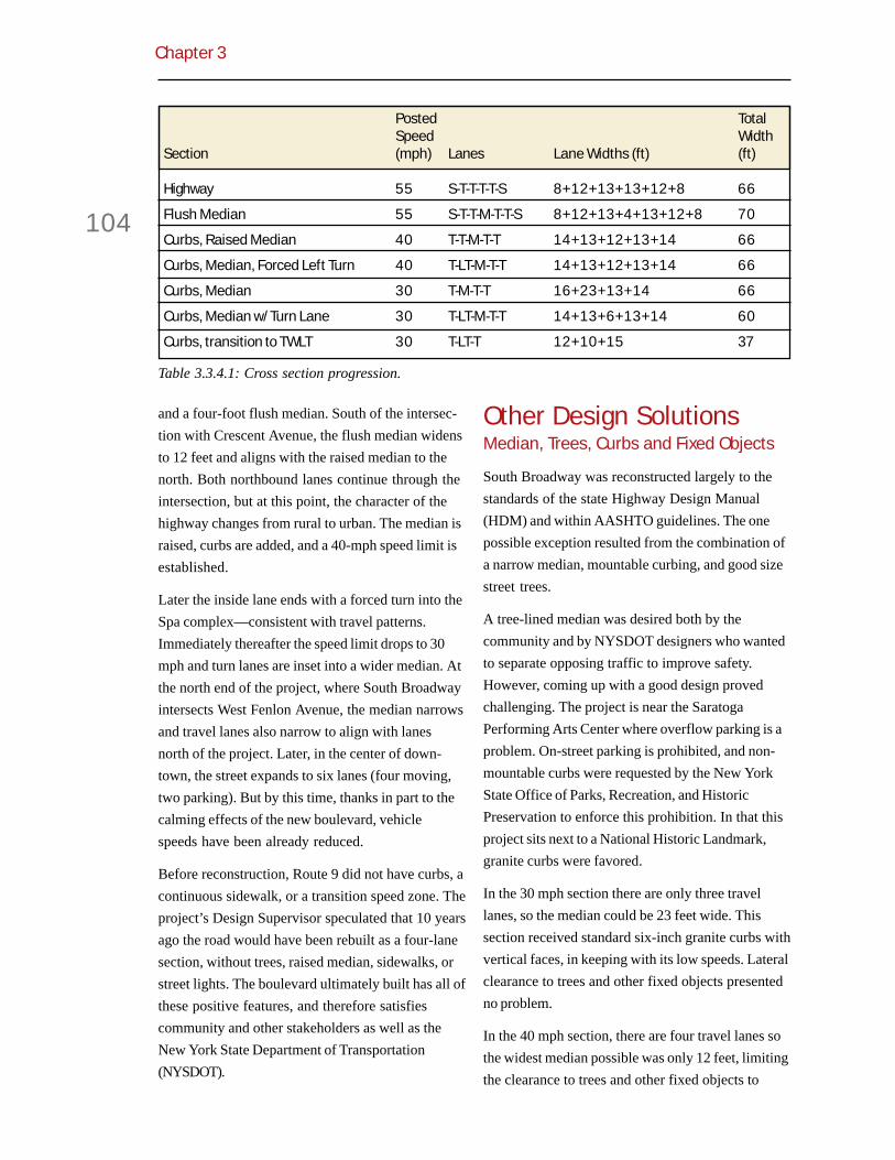
Chapter 3
104
and a four-foot flush median. South of the intersec-tion with Crescent Avenue, the flush median widensto 12 feet and aligns with the raised median to thenorth. Both northbound lanes continue through theintersection, but at this point, the character of thehighway changes from rural to urban. The median israised, curbs are added, and a 40-mph speed limit isestablished.
Later the inside lane ends with a forced turn into theSpa complex—consistent with travel patterns.Immediately thereafter the speed limit drops to 30mph and turn lanes are inset into a wider median. Atthe north end of the project, where South Broadwayintersects West Fenlon Avenue, the median narrowsand travel lanes also narrow to align with lanesnorth of the project. Later, in the center of down-town, the street expands to six lanes (four moving,two parking). But by this time, thanks in part to thecalming effects of the new boulevard, vehiclespeeds have been already reduced.
Before reconstruction, Route 9 did not have curbs, acontinuous sidewalk, or a transition speed zone. Theproject’s Design Supervisor speculated that 10 yearsago the road would have been rebuilt as a four-lanesection, without trees, raised median, sidewalks, orstreet lights. The boulevard ultimately built has all ofthese positive features, and therefore satisfiescommunity and other stakeholders as well as theNew York State Department of Transportation(NYSDOT).
Other Design SolutionsMedian, Trees, Curbs and Fixed Objects
South Broadway was reconstructed largely to thestandards of the state Highway Design Manual(HDM) and within AASHTO guidelines. The onepossible exception resulted from the combination ofa narrow median, mountable curbing, and good sizestreet trees.
A tree-lined median was desired both by thecommunity and by NYSDOT designers who wantedto separate opposing traffic to improve safety.However, coming up with a good design provedchallenging. The project is near the SaratogaPerforming Arts Center where overflow parking is aproblem. On-street parking is prohibited, and non-mountable curbs were requested by the New YorkState Office of Parks, Recreation, and HistoricPreservation to enforce this prohibition. In that thisproject sits next to a National Historic Landmark,granite curbs were favored.
In the 30 mph section there are only three travellanes, so the median could be 23 feet wide. Thissection received standard six-inch granite curbs withvertical faces, in keeping with its low speeds. Lateralclearance to trees and other fixed objects presentedno problem.
In the 40 mph section, there are four travel lanes sothe widest median possible was only 12 feet, limitingthe clearance to trees and other fixed objects to
Table 3.3.4.1: Cross section progression.
Posted TotalSpeed Width
Section (mph) Lanes Lane Widths (ft) (ft)
Highway 55 S-T-T-T-T-S 8+12+13+13+12+8 66
Flush Median 55 S-T-T-M-T-T-S 8+12+13+4+13+12+8 70
Curbs, Raised Median 40 T-T-M-T-T 14+13+12+13+14 66
Curbs, Median, Forced Left Turn 40 T-LT-M-T-T 14+13+12+13+14 66
Curbs, Median 30 T-M-T-T 16+23+13+14 66
Curbs, Median w/Turn Lane 30 T-LT-M-T-T 14+13+6+13+14 60
Curbs, transition to TWLT 30 T-LT-T 12+10+15 37

Flexible Design of New Jersey’s Main Streets
105
Figure 3.3.4.3: Four-foot flush median.
Figure 3.3.4.4: Twelve-foot flush median.
Figure 3.3.4.5: Twelve-foot raised median.
Figure 3.3.4.6: Forced left turn.
under six feet. Where the clearance is less than 10feet, the HDM requires the use of barrier curbs. Butsix-inch “barrier” curbs were seen as a hazard to out-of-control motorists at these higher operatingspeeds.
Working within these constraints, the projectdesigner put together a creative palette of solutions.
! The light fixtures in the median are onbreakaway bases, and thus are notfixed objects. The bollards are hollowcast aluminum, which crumble uponimpact. This has already been demon-strated (see below).
! The project designer found a type oftree, which in the opinion of the DOTEnvironmental Services Unit, couldmeet all HDM criteria. The AristocratPear tree (Pyrus Calleryana Aristo-crat) is a relatively small tree thatgrows upright and maintains acompact root ball. Under ideal growingconditions, the trunk may grow tomore than a four-inch caliper. Yet,constrained by a 12-foot median inSaratoga Springs’ climate, this tree willprobably not reach four inches. Inaddition, the compactness of its rootball may cause it to react like a shrubwhen hit by vehicle, just rolling over(or so DOT Environmental Servicesavowed).
Figure 3.3.4.7: Twenty-three foot raised medianwith turn bays.
Figure 3.3.4.8: Two-way left turn.

Chapter 3
106
Figure 3.3.4.9: Flush median.
Figure 3.3.4.10: Flush to raised median.
Figure 3.3.4.11: Forced left turn.
Figure 3.3.4.12: Median with turn bays.
! Four-inch “traversable” curbs with a30-degree slope were originallyselected. While consistent with DOTstandards, these curbs would not self-enforce the parking regulations. Also,during construction, these curbs ingranite were determined to be prohibi-tively expensive. A change order wasissued to standard four-inch mount-able type E curbs with a 45 degreebevel. From a safety standpoint it wasagreed that the expected reductions invehicle speed would allow this type ofcurb. It has worked well to preventcars from parking on the buffer stripsince construction.
In the end, the road was built with a tree-linedmedian, attractive light fixtures, relatively low curbs,and few signs. A similar section of road in Saratoga(with a median and trees) was constantly referencedfor its safety record. The flexibility shown inresearching and finding an appropriate solution is atestament to the quality of the project and staff.
Forced Left Turn
At Avenue of the Pines, a main entrance to the Spacomplex, a forced left turn condition existed beforethis project. Traffic in the inside lane must turn left,for the lane is not continued beyond the intersec-tion. This created a safety hazard, as through trafficoften got caught in the drop lane and had to reenterthe traffic stream.
In the new design this forced turn is formalized viathe highly visible median. The median opposite hasa mountable curb and breakaway bollards in case adriver should fail to make the turn and continuethrough the intersection. This provides a morecontext-sensitive design than the alternative ofcutting back the median to provide a large recoveryarea for reentering vehicles. In effect, the design ofthe drop lane is more urban than rural—consistentwith the goals of the project.

Flexible Design of New Jersey’s Main Streets
107
A review of crash history showed that the vastmajority of incidents involved turning vehicles andrear-ends. In 1995 additional signage was installedto aid drivers. It is unclear whether this had anyeffect on the crash rate. The addition of the medianseeks to further address these problems by physi-cally altering the roadway to reflect the operation. Inother words, the design reinforces the signage.
Following construction, the right hand bollard washit by a driver who, while turning onto SouthBroadway, swerved to avoid a red light runner. Noinjuries occurred as the bollard crumpled on cue.
Sidewalks
Standard-width sidewalks were added on both sidesof the street. The original road had a sidewalk inonly one quadrant, and it was of substandard width.Signalized intersections now have pedestrianactuated signals and marked crosswalks. Linkagesare provided to roads and paths in the State Park.
An added benefit of the crosswalks is to directpedestrians to different park entrances so as torelieve congestion at the main entrance.
Cycle Lanes/Paths
Another purpose of this project was to enhanceSaratoga’s cycle route system. According to theNYSDOT design manual, six-foot bike lanes or wideshared lanes are to be provided along all officialcycle routes. Prior to the reconstruction cyclistsrode in the wide, but varied, shoulders. This was achallenge as vehicle speeds and driver behavior,coupled with overflow parking during summerevents, compromised safety. The new outside lanes
Figure 3.3.4.13: Avenue of the Pines intersectionbefore.
Figure 3.3.4.14: Avenue of the Pines intersectionafter.
Figure 3.3.4.15: Missing bollard at Avenue of thePines intersection.
Figure 3.3.4.16: Evidence of a crash.
Table 3.3.4.2: Crash history at Avenue of Pines,1993-1995.
Rear- Fixed Over-Type End Turns Object taking TOTAL
Count 7 5 2 1 15
Percentage 57% 33% 13% 7% 100%

Chapter 3
108
are 14 to 16 feet wide and intended to be shared bycyclists and drivers. In addition, a mixed-use pathwas constructed through the park. Both get less usethan expected as cyclists seem to prefer the side-walks.
Performance FlexibilitySpeeds
In 1997, the 85th percentile speed of northbounddrivers (entering town) just south of Avenue of thePines was 53 mph. The posted speed at that timewas 55 mph. Studies performed about six monthsafter the project showed that speeds fell to 46 mph.
At West Fenlon Street, the combined 85th percentilespeed for traffic in both directions was 38 mph in1994. After the project the speed rose to 40 mph, anunexpected result that requires some analysis.
Volumes and LOS
A primary justification for the project was intersec-tion capacity. The previous road, while sufficient forthe volumes present, was largely uncontrolled interms of traffic operations. A review of the level ofservice found failure within 20 years at the WestFenlon Street intersection. This was addressedthrough the addition of a traffic signal. At otherlocations, left turn bays will provide additionalcapacity. The two southbound lanes remain in orderto maintain LOS exiting the city. In this direction,speed is of less concern as drivers are approachinga rural highway environment.
Figure 3.3.4.17: Former sidewalk condition.
Figure 3.3.4.18: New sidewalk condition.
Figure 3.3.4.19: Well-marked crosswalk andaccessible median.
Figure 3.3.4.20: Saratoga bike route map alongSouth Broadway.

Flexible Design of New Jersey’s Main Streets
109
Institutional Collaboration
Maintenance responsibility has been divided amongthe participating agencies. Half of the project iswithin the Saratoga Springs city limits and the citywill assume responsibility there. NYSDOT willmaintain the road and signals outside the city limits.The New York State Office of Parks, Recreation, andHistoric Preservation will maintain the new side-walks and pathways.
The decision to provide a context-sensitive gatewayincreased the cost of the project. This additionalcost was questioned but accepted by the localmetropolitan planning organization, the CapitalDistrict Transportation Committee. The City ofSaratoga Springs provided funding to remove all ofthe overhead utilities for the length of the projectand place them underground.
Public Outreach and Response
Responding to the governor’s EnvironmentalInitiative (EI), NYSDOT began to follow context-sensitive design principles in 1999. The EI definesCSD as a proactive approach that considers aproject within its natural and man-made context.Public input is to be sought throughout the designprocess.
Discussions pertaining to the reconstruction ofSouth Broadway began in 1997 between the city,NYSDOT, and New York State Office of Parks,Recreation and Historic Preservation. During thescoping process the boulevard treatment arose asthe preferred alternative. The fact that there wereclear project objectives assisted both in the accep-tance of the project and quality of design. Theproject has won internal design awards withinNYSDOT.
Following the success of this project, NYSDOT hasshown increased interest in “transition” designs forhighways as they enter communities. The agencyrecognizes the need to slow traffic through roaddesign, and at the same time, maintain traffic safety.The HDM is being revised to include more informa-tion on medians and curbs, as the burden iscurrently on the designer to demonstrate the effectof these elements on vehicle speed. Speed predic-tion models will also allow the agency to betterinterface with the public when a project’s statedpurpose is speed reduction.
Figure 3.3.4.21: Section with one lane inbound and two out.
Table 3.3.4.3: Intersection level of service.
Former No-build As builtCross street (1999) (2019) (2019)
Crescent Avenue A-C A-C A-C
Avenue of the Pines A-C A-D A-D
West Fenlon Street A-F B-F A-D(stop) (signal)

Chapter 3
110
Table 3.3.4.4: Project status summary.
Table 3.3.4.5: Data summary for South Broadway, Saratoga Springs, New York.
Project Status 2000 (Completed)
City Population 2,200
Adjacent Land Use Residential, Park
Road Classification Urban Principal Arterial
Road Ownership State/City
Design Exception Required Field Change
Project Cost $2.2 Million
Economic Data —
Element Before After
Number Of Lanes 2-4 3-4
Lane Width + offset, feet Varied 13-16
Shoulder Width or Cycle Lane, feet Varied 0-8
Street width, feet Varied 37-70
On-street Parking No No
On-street Parking width, feet — —
Sidewalk Width, feet Not continuous 5-8
Posted Speed, mph 30, 55 30, 40, 55
85th Percentile or Design Speed, mph 38-53 40-46
Vehicle Volume, ADT (DY-2004) 17,300 27,300 (DY 2019)
Level of Service C-F D (DY 2019)
Crash Data, reportable 22/year 9/year (since June 2000)
Truck Volume 7% 7%
Pedestrian Volume — +500%
Bike Volume — +500%
Corner Radii, feet No curbs Varies
Stopping Sight Distance, feet Substandard at one Improvedintersection

Flexible Design of New Jersey’s Main Streets
111
3.3.5 Westminster,Maryland, East Main Street(MD 32)
The first example of flexible roadway designfrom the Maryland State Highway Adminis-tration (MSHA) is East Main Street in
Westminster, or MD 32. This historic street wasfunctioning fine from a traffic standpoint in the earlyNineties, but eight blocks were in need of basereconstruction. Also, the underground utility lineswere in need of replacement and the storm drainsystem had to be upgraded.
Geometric FlexibilityUpon beginning the project, the design engineerchecked the Maryland Highway DevelopmentManual and, consistent with the standards at thetime, proposed widening the road to 40 feet. Theexisting cross section, ranging from 34 to 36 feet,was substandard from his perspective. Wideningwould have provided 12-foot travel lanes and eight-foot parking lanes on each side. It also would haveeliminated nearly all street trees and reduced thesidewalk width to two feet in places.
When she learned of the widening, a citizen activistbegan a campaign to preserve the street’s historiccharacter. She enlisted the mayor’s assistance, andthe mayor convinced the MSHA to redesign theproject in a way that would enhance the street’shistoric character. The redesign produced a consis-tent 36- to 38-foot paved width, with 10- to 11-foottravel lanes and eight-foot parking lanes. Thirty-fourof 42 existing street trees were preserved, and 118new trees were planted to create a more even andcontinuous canopy.
The operative roadway design standards at projectinception were those of the Maryland HighwayDevelopment Manual. The redesign would haverequired multiple design exceptions. The MSHA
Figure 3.3.5.1: East Main Street.
Figure 3.3.5.2: Westminster area map.
Figure 3.3.5.3: Street network. Table 3.3.5.1: Cross section comparison.
TotalLanes Parking Width
(ft) (ft) (ft)
Former 9-10 8 34-36
Former MSHAStandard 12 8 40
New10-11 7-8 36-38
At CurbExtensions 11 2 (offset) 26

Chapter 3
112
avoided this by discarding its own design manualand typical sections in favor of the more flexibleAASHTO Green Book, which has become the state’sde facto design manual. The redesign meets allAASHTO minimum dimensions.
The relationship between the curb extension andlane widths is interesting for the way it maintainslane consistency. While the lanes vary from 10 to 11feet, the street has a constant two percent slope forthe center 22 feet. From this point to the curb thecross slope is six percent. This gives the illusion ofconstant 11-foot lanes.
The curb extensions are six feet wide, generally thesame width as a parked car. This is appropriate forthis speed environment, but means that the lane atthe curb extension is realistically 13 feet wide. Thisis positive for cyclists as it is almost a standard 14-foot shared use lane. Yet the narrow appearance ismaintained by the contrasting concrete gutter pan.
Other Design SolutionsCurb Extensions
Landscaped curb extensions (known euphemisti-cally as planting areas) were added to protect parkedcars and shorten crossing distances for pedestrians.The planting areas were coordinated with mid-blockcrosswalks, intersections, and a driveway. Inaddition they provide space for pedestrian rampsoutside the central sidewalk area, and permit theramps to align directly with the crosswalks.
Marked Parking Bays
The curb extensions, while positive from trafficcalming and street crossing standpoints, raisedconcerns among downtown merchants about loss ofon-street parking. These concerns were allayedwhen MSHA showed that by marking individualparking spaces at 22 feet long, and thus eliminatingscattered parking patterns, Main Street would havemore parking capacity after the reconstruction thanbefore.
Table 3.3.5.2: Number of curb extensions.
Figure 3.3.5.7: Curb extension at pedestrian ramp.
Figure 3.3.5.6: Curb extension at driveway.
Figure 3.3.5.5: After construction.
Figure 3.3.5.4: During construction.
Curb Extensions Count
Intersection w/Crosswalk 3Mid-block w/Crosswalk 3Driveway 1Planting Area Only 6TTTTToooootaltaltaltaltal 1 31 31 31 31 3

Flexible Design of New Jersey’s Main Streets
113
Crosswalks
Crosswalks at intersections and mid-block wereaccentuated with colored brick pavers. Those atmid-block were coordinated with pedestriangenerators so that the walking public might be moreapt to use them. The mid-block crosswalks initiallyraised safety concerns within MSHA, since driversmight not anticipate pedestrians crossing at theselocations. In time, the colored pavers, curb exten-sions, and low-speed environment were judged toprovide adequate pedestrian visibility and driverresponse time.
Performance FlexibilitySpeed
The design speed for East Main Street is 30 mphwhile the posted speed is 25 mph. This is consistentwith standard practice, even though this is astraight, uncontrolled section of road. As suchdrivers could theoretically travel as fast as they
Figure 3.3.5.8: Mid-block crosswalk. Figure 3.3.5.10: Marked parking places.
Figure 3.3.5.9: New tree canopy.
Figure 3.3.5.11: Narrowed mid-block crossing.
Figure 3.3.5.12: Detail of brick pavers.
want, for the curb extensions, tree canopy and brickcrosswalks do little to physically restrict speed.Nevertheless the psychological effect of thesefeatures is unquestioned.

Chapter 3
114
Volume
In that the number of lanes was not reduced, norwas traffic control altered, the capacity of the roadwas largely unchanged. The level of service couldbe a little lower, given the increase in pedestrian andon-street parking activity, yet this was acceptable inWestminster.
Institutional Collaboration
The redesign and reconstruction involved collabora-tion between the City of Westminster and MSHA.MSHA paid for the reconstruction, and thentransferred the road to the city for operation andmaintenance. The transfer of control was consistentwith the changing function of East Main Street,which has functioned more like a local street sincethe MD 140 bypass opened. Technically thisportion of MD 32 was removed from the MarylandState Highway System after reconstruction, al-though it is still a signed route.
Could this road have been reconstructed to thesespecifications while remaining on the State HighwaySystem? Or was the transfer of ownership necessaryto effectuate this flexible design? Certainly, thetransfer of ownership made it easier to redesign the
road flexibly. The curb extensions would havecomplicated street sweeping and snow removal fordepartment maintenance crews. The use of concretepavers and extensive landscape materials couldhave complicated maintenance functions as well.Nonetheless, two policy changes make redesignslike Westminster’s Main Street not only feasible butnow preferred by MSHA: the first policy changewas the adoption of AASHTO’s Green Book as thestate’s design manual; the second was the decisionto treat all subsequent main street reconstructionsas 3R projects, leaving the existing cross sectionsand street trees alone unless there is a demonstratedsafety problem. As additional main streets arereconstructed in Maryland, they are being retainedon the State Highway System.
Public Response
In the end, the residents and merchants ofWestminster were delighted with the result, and
Figure 3.3.5.13: Narrowed intersection (notedetail of surroundingbuilt form).
Figure 3.3.5.15: MD 144 through Hancock after.
Figure 3.3.5.14: MD 144 through Hancock before.
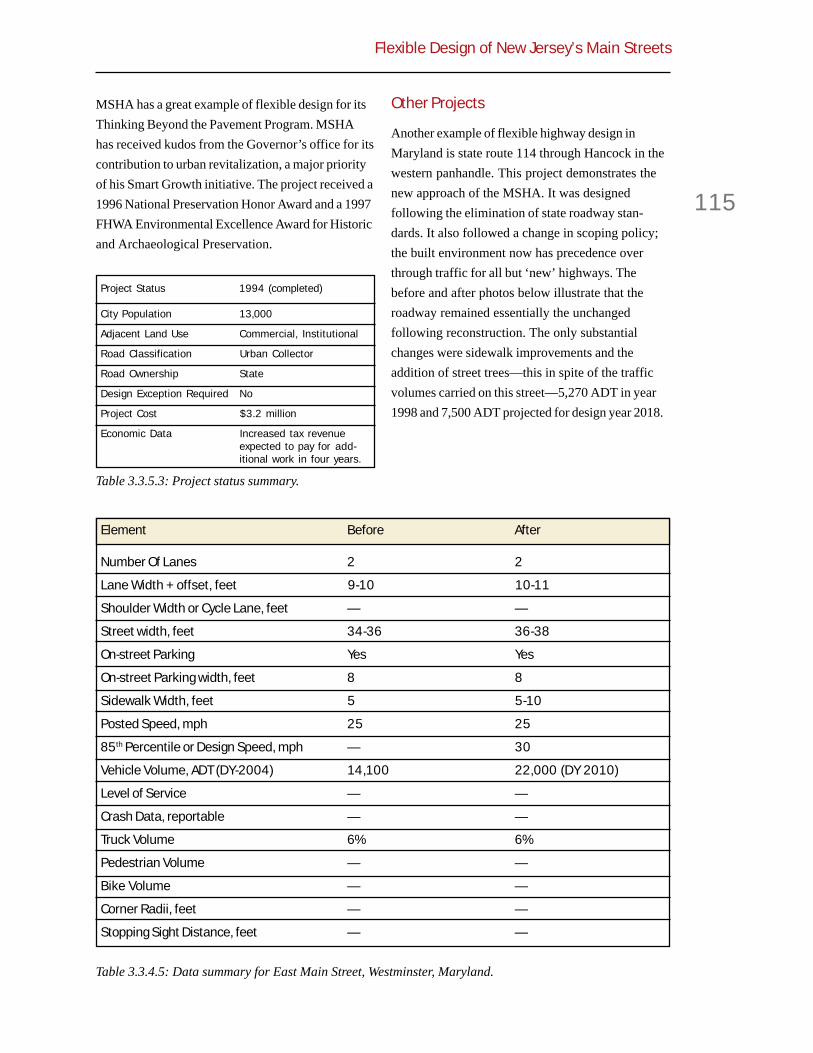
Flexible Design of New Jersey’s Main Streets
115
MSHA has a great example of flexible design for itsThinking Beyond the Pavement Program. MSHAhas received kudos from the Governor’s office for itscontribution to urban revitalization, a major priorityof his Smart Growth initiative. The project received a1996 National Preservation Honor Award and a 1997FHWA Environmental Excellence Award for Historicand Archaeological Preservation.
Other Projects
Another example of flexible highway design inMaryland is state route 114 through Hancock in thewestern panhandle. This project demonstrates thenew approach of the MSHA. It was designedfollowing the elimination of state roadway stan-dards. It also followed a change in scoping policy;the built environment now has precedence overthrough traffic for all but ‘new’ highways. Thebefore and after photos below illustrate that theroadway remained essentially the unchangedfollowing reconstruction. The only substantialchanges were sidewalk improvements and theaddition of street trees—this in spite of the trafficvolumes carried on this street—5,270 ADT in year1998 and 7,500 ADT projected for design year 2018.
Table 3.3.5.3: Project status summary.
Table 3.3.4.5: Data summary for East Main Street, Westminster, Maryland.
Project Status 1994 (completed)
City Population 13,000
Adjacent Land Use Commercial, Institutional
Road Classification Urban Collector
Road Ownership State
Design Exception Required No
Project Cost $3.2 million
Economic Data Increased tax revenueexpected to pay for add-itional work in four years.
Element Before After
Number Of Lanes 2 2
Lane Width + offset, feet 9-10 10-11
Shoulder Width or Cycle Lane, feet — —
Street width, feet 34-36 36-38
On-street Parking Yes Yes
On-street Parking width, feet 8 8
Sidewalk Width, feet 5 5-10
Posted Speed, mph 25 25
85th Percentile or Design Speed, mph — 30
Vehicle Volume, ADT (DY-2004) 14,100 22,000 (DY 2010)
Level of Service — —
Crash Data, reportable — —
Truck Volume 6% 6%
Pedestrian Volume — —
Bike Volume — —
Corner Radii, feet — —
Stopping Sight Distance, feet — —
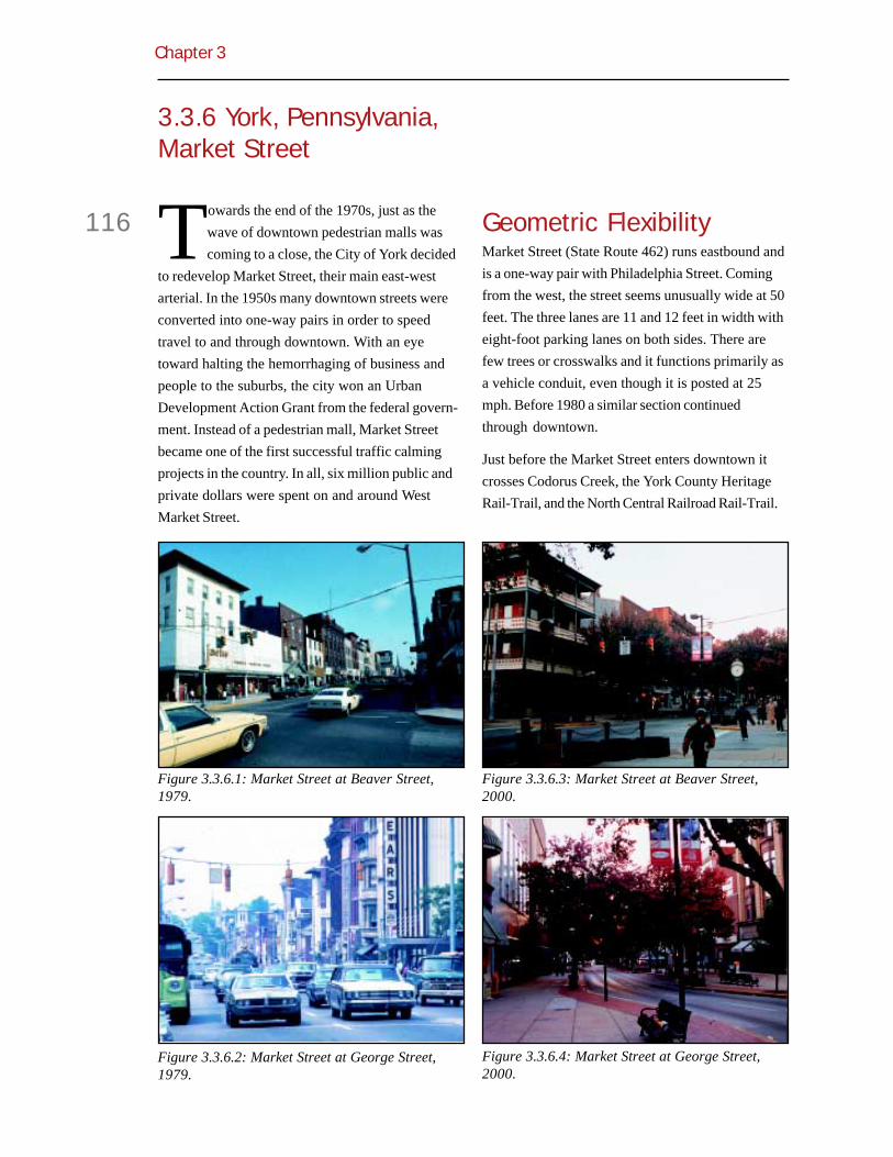
Chapter 3
116
3.3.6 York, Pennsylvania,Market Street
Towards the end of the 1970s, just as thewave of downtown pedestrian malls wascoming to a close, the City of York decided
to redevelop Market Street, their main east-westarterial. In the 1950s many downtown streets wereconverted into one-way pairs in order to speedtravel to and through downtown. With an eyetoward halting the hemorrhaging of business andpeople to the suburbs, the city won an UrbanDevelopment Action Grant from the federal govern-ment. Instead of a pedestrian mall, Market Streetbecame one of the first successful traffic calmingprojects in the country. In all, six million public andprivate dollars were spent on and around WestMarket Street.
Geometric FlexibilityMarket Street (State Route 462) runs eastbound andis a one-way pair with Philadelphia Street. Comingfrom the west, the street seems unusually wide at 50feet. The three lanes are 11 and 12 feet in width witheight-foot parking lanes on both sides. There arefew trees or crosswalks and it functions primarily asa vehicle conduit, even though it is posted at 25mph. Before 1980 a similar section continuedthrough downtown.
Just before the Market Street enters downtown itcrosses Codorus Creek, the York County HeritageRail-Trail, and the North Central Railroad Rail-Trail.
Figure 3.3.6.1: Market Street at Beaver Street,1979.
Figure 3.3.6.3: Market Street at Beaver Street,2000.
Figure 3.3.6.2: Market Street at George Street,1979.
Figure 3.3.6.4: Market Street at George Street,2000.

Flexible Design of New Jersey’s Main Streets
117
It is here that the traffic calming project begins. Theright lane must turn and the left and center lanescontinue straight. Truck traffic is directed right toKing Street where the signals were re-timed to speedtheir passage.
Passing through the first block of the project onefinds wider sidewalks, corner and mid-block curbextensions forming parking bays only on the right.The cross section is 30 feet. In the second block,what were the left and center lanes shift into thecenter and right lanes respectively. Parking is nowon the left side. At the end of the block the trafficshifts back to the left. The third block returns to thesame configuration as the first, with the addition ofan 8-foot contra-flow lane leading to a parkinggarage. A 4-foot median divides the two opposinglanes.
Figure 3.3.6.5: York area map. Figure 3.3.6.9: Downtown area plan.
Figure 3.3.6.6: Aerial view, 1972.
Figure 3.3.6.7: Aerial view, 1992.
Figure 3.3.6.8: Site plan.

Chapter 3
118
Table 3.3.6.1: Cross section comparison.
Figure 3.3.6.10: Market Street to the west ofdowntown (typical three-lane section).
Figure 3.3.6.13: Market Street through downtown(lane shift).
Figure 3.3.6.14: Lane shift plan.
Figure 3.3.6.11: Market Street as it entersdowntown (forced right turn).
Figure 3.3.6.15: Market Street at parking garage(conta-flow lane).
Figure 3.3.6.12: Forced right turn plan.
Curb-to-CurbSidewalk & Lane Widths Right of Way
Cross Section (ft) (ft)
Adjacent/orginial section 15+8+11+12+11+8+15 50/80
Pershing–Beaver 27+11+11+8+23 30/80
Beaver–George 22+8+11+11+28 30/80
George–Duke 27+11+11+8+23 30/80
George–Duke contra-flow 15+8+4+11+11+8+23 42/80

Flexible Design of New Jersey’s Main Streets
119
Other Design SolutionsIn addition to the lane shifts, the reborn MarketStreet contains other items that reinforce the lowspeed, pedestrian-friendly nature of the street.
Intersections
Crosswalks at intersections are set back 13 to 22feet, but still in line with pedestrian travel. This islargely accomplished through curb extensions. Theresultant “yield” space allows turning drivers to waitfor people in the crosswalk out of the way of themoving lanes. This increases both vehicular andpedestrian level of service, and reduces conflicts.
Corner radii have been reduced from 30 to 20 feet.This has the dual effect of slowing turning trafficwhile allowing the pedestrian ramp to be aligneddirectly with the crosswalk, simplifying travel in awheelchair. On the tip of the enlarged corners areplanters, trees and bollards. These define the cornerand help to keep errant vehicles off the sidewalk.
The signal timing is broken into three phases so asto temporally separate conflicting movements. PhaseA gives 28-34 seconds to Market Street. Phase Bprovides 18 seconds to the cross street and turningmovements. Phase C gives 18-24 seconds to thecross street through movement only, thus eliminat-ing any conflict with pedestrian traffic. While thetotal cycle is only 70 seconds, thus reducing overalldelay, the fact that drivers are allowed to turn (phaseB) before walkers get to cross (phase C) is problem-atic. A more progressive solution would be toprovide a leading pedestrian interval, therebyreinforcing pedestrian priority.
Mid-block Crosswalk
The trees, now 20 years old, provide much shadeand are set back just two feet from the curb. There isa well-marked mid-block crosswalk aligned with amid-block passageway. This leads to a farmersmarket, parking lots and connects to the rest of the
Figure 3.3.6.16: Contra-flow plan.
Figure 3.3.6.17: Market Street as it leavesdowntown (typical two-lane section).
Figure 3.3.6.18: Plantings and set back crosswalk.
Figure 3.3.6.19: Typical signal timing.

Chapter 3
120
street network. The crosswalk is uncontrolled tominimize pedestrian delay, and the curbs areextended to reduce exposure time.
Performance FlexibilitySpeeds
The 13-foot offset in 66 feet has a design speed of28-29 mph as calculated using British designguides.3 Set in a posted 25 mph zone this is consis-tent with US engineering practice, yet it limits theability of motorists to drive at excessive speeds.
Volumes
When the project was completed, some of the traffic(especially trucks) was diverted to King Street. In1986 Market Street carried 13,803 ADT through thetwo-lane section. By 1989 the ADT had grown to17,518 to the west of the project. The city uses a 2.2percent growth projection and from that one canderive and compare traffic volumes for the two-laneand three-lane sections.
Institutional Collaboration
As with many projects where a town wishes toreclaim its street from through traffic, the city of Yorkdesigned, engineered and constructed this projectwith the help of a consultant, WMRT (Wallace,McHard, Roberts & Todd) Planners & Engineers.They designed it essentially independent of thecounty and state highway departments. Although itis still officially a state route, the state highwaydepartment transferred maintenance responsibilityto the city at the time of the project.
Public Response
The success of the traffic calming of Market Streetcan be measured by other traffic calming projects itspurred. The city recently began a five million dollarproject to enhance the retail and streetscape
Table 3.3.6.2: Average Daily Traffic.
Figure 3.3.6.20: Mid-block crossing aligned withmid-block passage.
Figure 3.3.6.21: Curb extension and signage atmid-block crosswalk.
3 DETR Traffic Advisory Leaflets 9/94 and 12/97.
1980 Per 2000 PerADT Lane ADT Lane
AdjacentSection(3 lanes) 14,100 4,700 22,300 7,433
ThroughProject(2 lanes) - - 18,700 9,350
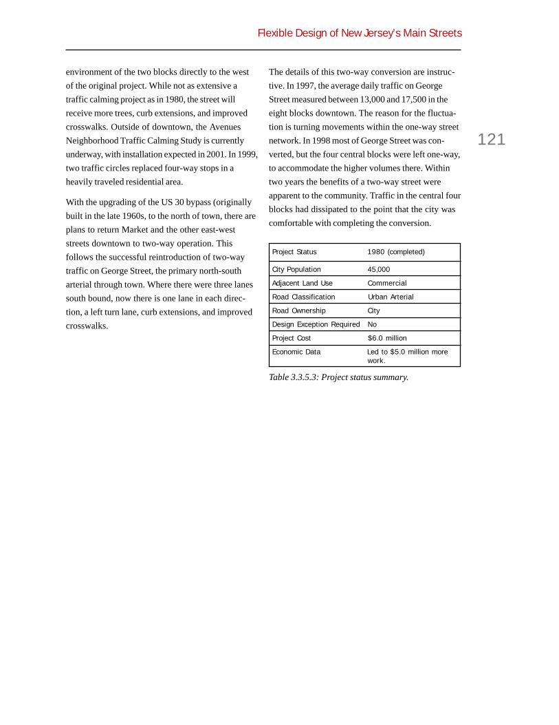
Flexible Design of New Jersey’s Main Streets
121
environment of the two blocks directly to the westof the original project. While not as extensive atraffic calming project as in 1980, the street willreceive more trees, curb extensions, and improvedcrosswalks. Outside of downtown, the AvenuesNeighborhood Traffic Calming Study is currentlyunderway, with installation expected in 2001. In 1999,two traffic circles replaced four-way stops in aheavily traveled residential area.
With the upgrading of the US 30 bypass (originallybuilt in the late 1960s, to the north of town, there areplans to return Market and the other east-weststreets downtown to two-way operation. Thisfollows the successful reintroduction of two-waytraffic on George Street, the primary north-southarterial through town. Where there were three lanessouth bound, now there is one lane in each direc-tion, a left turn lane, curb extensions, and improvedcrosswalks.
The details of this two-way conversion are instruc-tive. In 1997, the average daily traffic on GeorgeStreet measured between 13,000 and 17,500 in theeight blocks downtown. The reason for the fluctua-tion is turning movements within the one-way streetnetwork. In 1998 most of George Street was con-verted, but the four central blocks were left one-way,to accommodate the higher volumes there. Withintwo years the benefits of a two-way street wereapparent to the community. Traffic in the central fourblocks had dissipated to the point that the city wascomfortable with completing the conversion.
Table 3.3.5.3: Project status summary.
Project Status 1980 (completed)
City Population 45,000
Adjacent Land Use Commercial
Road Classification Urban Arterial
Road Ownership City
Design Exception Required No
Project Cost $6.0 million
Economic Data Led to $5.0 million morework.
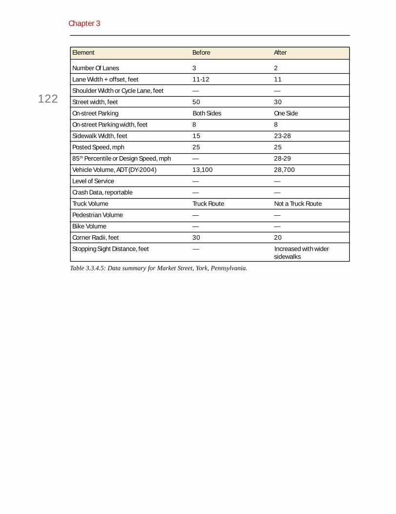
Chapter 3
122
Table 3.3.4.5: Data summary for Market Street, York, Pennsylvania.
Element Before After
Number Of Lanes 3 2
Lane Width + offset, feet 11-12 11
Shoulder Width or Cycle Lane, feet — —
Street width, feet 50 30
On-street Parking Both Sides One Side
On-street Parking width, feet 8 8
Sidewalk Width, feet 15 23-28
Posted Speed, mph 25 25
85th Percentile or Design Speed, mph — 28-29
Vehicle Volume, ADT (DY-2004) 13,100 28,700
Level of Service — —
Crash Data, reportable — —
Truck Volume Truck Route Not a Truck Route
Pedestrian Volume — —
Bike Volume — —
Corner Radii, feet 30 20
Stopping Sight Distance, feet — Increased with widersidewalks

Flexible Design of New Jersey’s Main Streets
123
Appendix A.1
TechnicalReviewCommittee
The first task of this project was to establisha Technical Review Committee (TRC) ofleading experts and practitioners in the
field of context-sensitive design. These profession-als were identified through outreach to prominentplanners and engineers, postings on national e-maillist serves, and recommendations from DOT.
The TRC played a significant role in this project.The group met at the midpoint of the project toreview and comment on progress, and redirectefforts as necessary.
The TRC also participated in a Main Street VisualPreference Survey to help the TPI team betterunderstand what constitutes a main street, and whatattributes make a particular main street a good one.Results of the survey are presented in AppendixA.4.
Finally, the TRC was consulted on the nature ofconflicts between DOT standards and communityobjectives, and on means for resolving them. Theend product is the conflicts-solutions matrix inSection 2.6.
Brief biographies of the members follow.
Charles B. Adams, RLA, Director of EnvironmentalDesign with the Maryland State Highway Adminis-tration. Mr. Adams is chair of the CommunityInvolvement Subcommittee for Maryland’s “Think-ing Beyond the Pavement” initiative. The statedgoal of the initiative is to integrate highwaydevelopment with community and environmentpreservation. Maryland has taken the lead in anational effort, coordinated by AASHTO and the
National Highway Cooperative Research Program, topromote context-sensitive design.
Janine G. Bauer, JD, Executive Director of the Tri-State Transportation Campaign, Inc., New York, NY.Ms. Bauer coordinates and supervises collaborativeprojects of thirteen member organizations promoting“centered” land use, rail freight, sustainable portinvestments, expanded transit, and environmentally-friendly transportation infrastructure spending. Sheconducts policy and legal analyses associated withtransport, economic, and environmental issuesfacing New York, Connecticut, and New Jersey.
James M. Daisa, PE, Fehr & Peers Associates.Among his publications, Mr. Daisa authoredCreating Livable Streets: Street Design Guidelinesfor 2040 for Portland Metro (Portland, Oregon’smetropolitan government). The publication won theEnvironmental Protection Agency’s “Way to Go”Award in 1998. Mr. Daisa has been in charge ofmost of the traffic engineering for land developmentprojects planned by Peter Calthorpe, a leading NewUrbanist planner.
Michael Moule, PE, City Traffic Engineer,Asheville, NC. Before starting his current job asCity Traffic Engineer of Asheville, Mr. Moule wasBicycle and Pedestrian Facility Specialist at OregonDOT. There, he rotated among offices of highwayconstruction, preliminary highway design, andbridge design. Mr. Moule uses his experience withalternate transportation modes and his backgroundin transportation engineering to provide the City ofAsheville with a balanced transportation system.
Carlos Rodrigues, PP, AICP, New Jersey Office ofState Planning. Mr. Rodrigues is coordinator ofDesigning New Jersey. He is responsible for policydevelopment in the areas of physical planning andurban design and is involved with a variety ofactivities related to implementation of the commu-

Appendix A.1
124
nity design vision of the State Plan. He has workedin Europe, Asia, and Canada, for a variety of privateand public organizations.
David Scott, PE, Director of Project Developmentwith the Vermont Agency of Transportation.Vermont is the acknowledged leader among statesthat have taken up the ISTEA challenge to tailorhighway design standards to state needs. Mr. Scott ischarged with developing projects according to thenew policies and standards, and as such has dailyinvolvement with context-sensitive highway design.
Ben Yazici, PE, Director of Public Works/FinancialServices, Sammamish, WA. Mr. Yazici has 19 yearsof management experience, 10 years as AssistantCity Manager/Public Works Director/City Engineer.He is a registered Professional Engineer in theStates of Washington and Oregon. His context-sensitive design projects in Sammamish, UniversityPark, and Gig Harbor recently won Mr. Yazici anational award from the Surface TransportationPolicy Project, Walking Magazine, and WalkableCommunities, Inc.

Flexible Design of New Jersey’s Main Streets
125
Appendix A.2
From Highway toMy Wayby Reid Ewing
Reproduced from Planning magazine, January 2000(some material deleted during the editorial processhas been reinserted).
You know the world is changing wheneveryone from the Federal HighwayAdministration to state and local transpor-
tation officials uses words such as “flexible” and“context-sensitive” to describe highway design.Now that the nation’s highways are nearly complete,transportation professionals are turning their sightson local communities and the inherent links betweentransportation systems and surrounding land uses.
There is a lot of confusion about exactly whatconstitutes context-sensitive highway design, whatlatitude exists under current standards and guide-lines, what tort liability attaches to such efforts, andwhat effect context-sensitive designs will have ontraffic safety and service levels. This article seeks tosort out myth from fact.
Main Street Destroyed
In the course of writing Best Development Practices(APA Planners Press, 1996), I visited every medium-sized town with any historic character in the state ofFlorida. I was on a quest for the best traditionalsmall towns in the state, hoping to find lessonsapplicable to contemporary development projects. Infact, I found very few good examples, mostlybecause of what happened along Main Street.
Main Street, usually part of the state highway
system, no longer functioned as a comfortableshopping street. It was too wide, and on-streetparking had been removed, street trees replaced withasphalt, and sidewalks narrowed. Strip commercialdevelopment seemed the only practical land use.The traditional towns that did end up in the book,such as Dade City, had somehow managed to evadethe standard DOT definition of “progress.”
The problem of context-insensitive highways is not,of course, unique to Florida, nor to small towns, norto state highways. Instead of gracious boulevards,avenues, and shopping streets, America’s urbanareas are crisscrossed by arterials and collectorsthat move traffic but have no power to move mens’souls.
DOTs vs. dots
Here are several examples proving that change is inthe air. U.S. Route 6 narrows to two lanes as it runsthrough the town of Brooklyn, Connecticut. Sightdistance is less than 250 feet at one point, drivewaysare closely spaced, and there is little roadsideclearance should a driver lose control. Yet trafficspeeds through the town still range up to 54 mph.
A 1991 state plan sought to correct these dangerous
Figure A.2.1: Preserved main street, Dade City,Florida.

Appendix A.2
126
conditions by widening the road to four lanes,straightening the alignment, and adding eight-footshoulders. The village appealed the plan, and theConnecticut Department of Transportation wentback to the drawing board.
ConnDOT’s next proposal was for a bypass aroundthe town, which was also rejected. Finally, afteryears of additional planning, a compromise wasreached in 1998. It keeps the existing alignmentthrough the town center, retains the two-lane crosssection, adds narrow shoulders and standard-widthsidewalks, and realigns the road marginally at themost dangerous curve. Reconstruction will becompleted in 2003.
In Albuquerque, New Mexico, Isleta Boulevard is atwo-lane road with no sidewalks, no curbs, nolandscaping or other amenities. The tendency ofdrivers to use the shoulder to pass left-turningvehicles on the right makes driving on IsletaBoulevard a free-for-all. The engineers’ solution wasto widen the southern leg of Isleta Boulevard fromtwo to five lanes, two travel lanes in each directionand a continuous left turn lane in the center.
Activists, who had witnessed the decline ofcommerce and street life on a nearby street after itwas five-laned, challenged the EnvironmentalAssessment (EA) of the project and Finding of NoSignificant Impact (FONZI). Their grounds: safetyproblems with the current roadway were notdocumented, only assumed; land-use impacts werenever analyzed; and more context-sensitive highway
design alternatives were not considered. FHWAagreed and refused to accept the EA and FONZI.This led to a new hybrid design, with the centralsection of road widened to only three lanes,sidewalks added, and landscaped median islandsinstalled.
In Anchorage, Alaska, engineers proposed theconversion of 15th Avenue into a one-way coupletwith 14th Avenue after a safety study documentedhigh accident rates and substandard geometrics.Residents of the adjacent Rogers Park neighbor-hood had seen one-way couplets in operation inmidtown, and this was exactly what they didn’twant. The couplets moved traffic efficiently butdivided the community much as a freeway would.
And so began a four-year process of redesign thatin 1998 resulted in a four-lane, tree-lined boulevardon the east end, and a narrowed three-lane crosssection on the west. When construction is com-pleted later this year (2001), travel lanes will bemaintained at their current 11-foot width, andshoulders excluded. Instead of shoulders, widegutter pans will provide a refuge area and bike-friendly surface. Sidewalks will be set back from thestreet for the first time.
In Westminster, Maryland, the base layer of EastMain Street needed reconstruction, undergroundutility lines had to be replaced, and the storm drainsystem needed upgrading. After checking theMaryland Roadway Design Manual, the districtengineer proposed widening the road to 40 feet.
Figure A.2.2: Section of Isleta Boulevard requiringreconstruction, Albuquerque, New Mexico
Figure A.2.3: Reconstructed northern section ofIsleta Boulevard, Albuquerque, New Mexico

Flexible Design of New Jersey’s Main Streets
127
Widening would have provided 12-foot travel lanesand eight-foot parking lanes on each side. It alsowould have eliminated nearly all street trees andreduced the sidewalk width to two feet in places.
After learning about the widening, a local residentbegan a campaign to preserve the street’s historiccharacter. She appealed to the mayor, who con-vinced the Maryland State Highway Administrationto reconstruct within the street’s existing dimen-sions. The result is a classic main street with “bulb-out” curb extensions at intersections, midblockcrosswalks, hundreds of additional street trees, andbrick surfacing in the crosswalks.
In these and many other cases uncovered in ourresearch, the need for road improvements wasundeniable, but standard design solutions wereunacceptable to the people most affected by them—those along the right-of-way. The resulting tensionbetween DOT and community goals led to compro-mise and context-sensitive designs.
Reform at the Top
Before 1991, all roads built in the U.S. and paid foreven in part with federal funds had to meet guide-lines in the American Association of State Highwayand Transportation Officials (AASHTO) Green Book(A Policy on Geometric Design of Highways andStreets). If officials wanted to do somethingdifferent, their only options were to seek design
exceptions from the Federal Highway Administrationor to build entirely with state and local funds.
The Intermodal Surface Transportation EfficiencyAct of 1991 (ISTEA) changed all of that by creatinga National Highway System made up of the inter-state system and other high-performance statehighways, 160,000 miles of roadway in all. Otherroads became eligible for federal funding under aseparate surface transportation program. For roadsnot on the NHS, ISTEA gave states latitude to adoptalternative design, safety, and construction stan-dards.
ISTEA was followed by two other milestones. TheNational Highway System Act of 1995 provided thateven NHS highways (other than Interstate high-ways) could be designed to take into account theenvironmental, scenic, aesthetic, historic, commu-nity, and preservation impacts of any proposedactivity. Two years later, the Federal HighwayAdministration published Flexibility in HighwayDesign, which forcefully advocates flexible designof highways running through communities, encour-aging highway designers to exercise flexibility withinexisting AASHTO guidelines.
Reform in the States
At the state level, much of the effort to promotecontext sensitivity has been process- and people-oriented. Five states (Connecticut, Kentucky,
Figure A.2.4: East Main Street duringreconstruction, Westminster, Maryland
Figure A.2.5: East Main Street as reconstructed,Westminster, Maryland

Appendix A.2
128
Maryland, Minnesota, and Utah) are participating ina joint FHWA/AASHTO effort to train engineers incontext sensitivity through the National CooperativeHighway Research Program (NCHRP). Many states,including New Jersey, have launched training effortsof their own. The New Jersey training consists offive day-long sessions on such unconventionaltopics (at least for highway engineers) as placemaking, respectful communication, conflict manage-ment, and traffic calming.
While such efforts are laudable, they inevitably runup against engineering constraints unless DOTstandards and policies are revised. Michael King, aconsultant on the NJDOT flexible highway designproject, surveyed more than a dozen states to findout about their efforts to develop new standardsand policies. His conclusion: Substantive changesare happening all over the United States.
Don’t Blame the Green Book
King found that few states have adopted sub-AASHTO geometric standards. Among those thathave, deviations from Green Book values arerelatively slight. The difference between the crosssectional width of a two-lane urban arterial underVermont’s much heralded design standards and thatunder the Green Book minimums is only three feet(43 vs. 46 feet). Notably, Dave Scott, Director ofProject Development and keeper of the Vermont
standards, has advised our New Jersey study teamnot to recommend anything less than AASHTOminimums because there is little to gain on urbanmain streets.
This is not to say that the AASHTO Green Book iswithout shortcomings. Its design guidelines areoften based on studies dating from a time whentires, braking systems, pavements, and vehicledimensions were less forgiving than today’s.However, these guidelines mostly affect the designof high-speed rural roads. The issue in the NewJersey study is whether good urban streets can beaccomplished under AASHTO guidelines.
Here are some of the AASHTO guidelines for urbanarterials:
! Design speed. AASHTO allows designspeeds as low as 30 mph in centralbusiness districts and intermediateareas. Posted speeds would ordinarilybe considerably lower.
! Lane width. The minimum lane width is3.0 m (10 ft) for urban arterials withlittle or no truck traffic. A minimum of3.3 m (11 ft) is prescribed for generaltraffic on urban arterials designed forspeeds up to 37 mph.
! Shoulders. AASHTO declaresshoulders “desirable on any highway,and urban arterials are no exception.”However, in urban contexts whereright-of-way is limited, the Green Bookneither requires shoulders norestablishes minimum widths.
! Setback of street trees. On curbedsections, the minimum clearance fromthe curb face is 1.5 feet. A 3.3-footclearance is considered desirable,particularly near intersections anddriveways where turning vehicles mayoverhang the curb.
! Midblock crosswalks. AASHTO isneutral on these.
! On-street parking. Parallel parking isallowed where adequate streetcapacity is available.
Figure A.2.6: Vermont vs. AASHTO minimums.

Flexible Design of New Jersey’s Main Streets
129
! Corners. Corner radii of 10 to 15 feetare reasonable under constrainedconditions. On arterials carrying highvolumes, larger radii are recommended(in some cases, much larger) tofacilitate turns to and from the throughlanes.
! Pedestrian refuge islands. Medianislands are encouraged where spacepermits.
! Sidewalks. The minimum border width,including sidewalk and planting strip,is 8 feet; a 12 foot border is preferred.
! Barrier curbs. Barrier curbs areencouraged in areas of high pedestriantraffic and speeds up to 37 mph, or ondiscretionary basis, up to 50 mph. Athigher speeds, barrier curbs do not actas barriers anyway.
The conclusion: It appears that we cannot place toomuch blame on the Green Book for the sorry state ofurban streets.
Liability Isn’t the Issue, Either
Governments used to have general immunity fromtort liability, but that has changed since the 1960s,as various courts and legislatures made it possiblefor individuals and groups to sue in cases wheregovernment fails to exercise due care in its deci-sions.
Government decisions are now divided into twoclasses: discretionary (planning decisions) andministerial (operational decisions). Discretionarydecisions involve a choice among valid alternativesand are generally immune from tort claims. Ministe-rial decisions leave minimal leeway for personaljudgment and are not immune.
As part of our study for NJDOT, we surveyedstatutory and recent case law in 16 states. With thesole exception of local roads in Vermont, all stateshad replaced sovereign immunity with more limiteddiscretionary immunity.
New Jersey has a Tort Claims Act that leaves thestate almost completely immune from tort liability
resulting from design-related decisions. All it takesis for the right body or person to approve a design(or the standards on which a design is based).
At the other extreme is Georgia, whose supremecourt held in DOT v. Brown (1996) that the design ofa roadway is an operational function, not coveredby discretionary immunity: “Only the decision tobuild, and not where or how it is built, is immune.”Between these extremes are states such as Californiaand South Carolina, which provide design immunitybut allow it to lapse as conditions change. From our16-state survey, we don’t find tort liability much ofan excuse for the sorry state of urban streets.Instead, we have identified some real culprits.
Put the Blame Here
AASHTO’s Green Book offers design policies andguidelines, not standards. For each design element,AASHTO typically provides a range of acceptablevalues, from a minimum value to a more desirabletarget value.
Figure A.2.7: “Green Book” applied by MarylandState Highway Administration.

Appendix A.2
130
For an AASHTO guideline to become a standard, itmust be adopted by a responsible agency. Manystates have adopted standards toward the middle orupper end of the AASHTO ranges, on the theorythat if some is good, more is better. County and cityengineers have then blindly adopted state stan-dards.
As noted, Maryland’s lane width standards wouldhave encroached on trees and sidewalks in the townof Westminster. Those standards exceededAASHTO minimums. Not only were these particularstandards thrown out, but the experience convincedBob Douglass, the Maryland State HighwayAdministration’s deputy chief engineer, that thestandards should be thrown out wholesale.
In 1998, Douglass wrote a memo banning the use ofthe state’s highway design manual. He found thatthe templates were generally oversized (especiallystopping sight distance and vertical curves) andstymied creativity among engineers. The agencywas losing legal challenges when an element wasbelow the state minimum value, but above the GreenBook value. Now the agency relies exclusively onthe Green Book.
In the Wrong Class
Another culprit is misclassification of streets.Streets and highways in this country are classifiedby location—urban or rural—and by function:arterial, collector, and local. There is a directrelationship between classification and designstandards. Classification determines design speed,design vehicle, and cross section (lane width,shoulder width, and type and width of median).
The U.S. classification system has been criticized forignoring distinctions among contexts and amongroadway functions. An urban arterial conforms tothe same basic standards whether it is a main streetor a bypass.
Misclassification of streets commonly occurs fortwo reasons. A small town, village, or hamlet fails to
meet the definition of urban. That community mayend up with a main street designed to rural stan-dards. This was true in Brooklyn, Connecticut,before the compromise described at the beginning ofthis article.
The simple solution to this problem is to treat anyplace that is built up as urban, regardless of itscensus designation. The Federal Highway Adminis-tration policy is simple: If it looks urban, use urbanstandards.
The other common case of misclassification occursas road functions change over time. In Westminster,Maryland, East Main Street had always been part ofMaryland State Route 32. It began functioning morelike a local street when the State Road 140 bypassopened. Accordingly, this portion of Route 32 wasremoved from the Maryland state highway systemafter the street was reconstructed, and the cityassumed responsibility for its operation andmaintenance. Other examples of misclassificationinclude Sunset Drive (State Route 986) in SouthMiami and Springfield Avenue (State Route 124) inMaplewood, New Jersey.
Level of Disservice
Level-of-service standards are yet another obstacleto context-sensitive design. While there is a legalimperative to provide safe roads, there is no suchreason to provide free-flowing roads. Some conges-tion may be desirable in a downtown. After all, adowntown without traffic isn’t a very excitingdowntown.
Virtually all DOTs have adopted level-of-servicestandards. Typically, the standard for urban areas isC or D, while the standard for suburban areas is B orC. As traffic volumes increase to the point where thestandard is no longer met, a road and its intersec-tions often will be widened regardless of the effectson adjacent land uses.
The alternative is to accept congestion in areas thatfunction as destinations. Since 1993, Florida has

Flexible Design of New Jersey’s Main Streets
131
allowed its local governments to exempt streetsthrough downtowns and urban redevelopment areasfrom level-of-service standards. The effectivestandard becomes level of service F. Many citiesand towns have taken this option.
West Palm Beach, for example, has adopted level-of-service E as its standard and is seeking a completeexemption from level-of-service standards for muchof the city. This city keeps an eye on both lowvolume-to-capacity ratios (less than 0.6) and highones (greater than 0.9). A low volume-to-capacityratio may offer an opportunity—a place where thestreet can be narrowed and street life encouraged bymeans of widened sidewalks, on-street parking, andlandscaped curb extensions and islands.
Sunset Drive (SR 986) in South Miami once func-tioned as the city’s main street, and the city wantedto reclaim the street as part of a downtown redevel-opment plan. To slow traffic and reduce crossingdistance, the existing four- or five-lane cross sectionhas been narrowed to three lanes. The roadwaynarrowing permits wider sidewalks, additional streettrees, and outdoor dining. Florida Department ofTransportation (FDOT) initially opposed a decline inlevel of service on its road. The solution was to de-designate this last section of SR 986, turn thesection over to the city, and have the lane reductionoccur within the city’s jurisdiction. The two east-bound travel lanes continue through the intersec-tion with US 1 (the western boundary of the city),
the inside lane ending in a trap left lane a block intothe city. Roadway level of service is thus maintainedat LOS E on the westbound approach, underFDOT’s jurisdiction. The one westbound laneapproaching US 1 has less carrying capacity thanthe previous configuration. But the resulting LOS Ffalls within the city’s jurisdiction.
It is worth noting that several of the context-sensitive projects we studied have improved or atleast maintained roadway level-of-service despitenarrowed roadways. How? Through clever treatmentof intersections, where most delays occur.
The Standard Cross Section
Nearly all state DOTs include typical sections—another culprit—in their road design manuals. If anarea is classified as urban, and a road is functionallyclassified as a principal arterial, the typical sectionfor an urban principal arterial becomes the defaultroadway.
Typical sections inhibit flexible and context-sensitive design in two ways. First, where right-of-way is constrained, something must be sacrificed tomaintain standard travel lanes, and it is usually thesidewalk, landscape buffer, or parking lane. Also,there is a tendency to adopt a single, typical sectionfor an entire stretch of road, even when conditionschange along its length. Having a single typical
Figure A.2.8: Sunset Drive before reconstruction,South Miami, Florida.
Figure A.2.9: Sunset Drive after reconstruction,South Miami, Florida.

Appendix A.2
132
section is convenient for the design engineer andconstruction crew, but it is not good policy.
The proposed five-lane section over the length ofsouthern Isleta Boulevard (see above) createdexcess capacity at the midpoint, and correspond-ingly higher speeds and higher costs. The hybriddesign with a three-lane section in the middle willsave $4.5 million on right-of-way acquisition andconstruction costs. The tendency to use a singletypical section is also evident in the Brooklyn casestudy at the beginning of the article.
An even more dramatic example is found in SaratogaSprings, New York. South Broadway (US 9) changesfrom a four-lane, semi-rural highway with a stripedmedian and posted speed of 55 mph to a three-laneurban road with a raised median, single northboundlane, and posted speed of 30 mph, all in a stretch of1,800 feet.
By all accounts, the section in question would have
been reconstructed as a uniform four-lane roadwaywith a flush median, but for two things. First, in1999, New York State started an EnvironmentalInitiative, with context-sensitive design at its heart.Second, the highway passes Saratoga Spa StatePark, the Lincoln Baths, and the Museum of Dance.Something special, more like a gateway, wasrequired. Ultimately, a series of roadway sectionsgot built that make a smooth transition from thehigh-speed semi-rural environment to the south tothe low-speed urban environment to the north (seeFigure A.2.6).
The Four Rs
Roads that are being resurfaced, restored, orrehabilitated (so-called 3R projects) do not have tobe upgraded to current geometric standards.Instead, states can (and some do) make them subjectto special standards below those of AASHTO—
Figure A.2.10: Multiple sections heading into town on US 9, Saratoga Springs, New York.

Flexible Design of New Jersey’s Main Streets
133
with the blessing of the Green Book. By contrast,under state and federal policies, roads reconstructeddown to their bases must be brought up to currentstandards.
In a constrained main street environment, there is noreason to treat 3R and reconstruction projectsdifferently. In both cases, designers already knowhow a road performs based on historical accidentand other data. The Maryland State HighwayAdministration reached this conclusion inWestminster, and now leaves existing cross sectionsalone unless there is a documented crash problem.
Exceptions to the Rules
The Federal Highway Administration grants designexceptions on the National Highway System, andthe same is true for state or local DOTs on non-NHSroads. Between 1997 and 1999, NJDOT engineersrequested and received design exceptions for 81projects, including most major highway projectsundertaken by the state.
From our review of the 81 reports, exceptions aretypically requested in order to save money, not topreserve context. Here is a typical scenario: A roadis being reconstructed, and a sharp curve must to bestraightened to meet the standard for horizontalcurvature. However, someone’s house or businesswould be taken, some park or cemetery would beencroached on, a lot of extra asphalt would have topoured, or some other big expense would beincurred.
And so the design engineer checks crash statisticsfor the location in question, focusing on the typesof crashes associated with substandard horizontalcurves, and finds that the curve in questiongenerates only an average number of crashescompared to state norms. Noting that substantialcosts can be avoided by allowing a substandard
horizontal curve, a design exception is requestedand granted.
Sometimes context also is taken into account, aswith a road and bridge project in an historic districtof Oxford Township, New Jersey. But this is a rareoccurrence.
Let’s Use Common Sense
Gary Toth, one of the overseers of our research atNew Jersey DOT, keeps saying that context-sensitive design is just a matter of common sense. Ifthe designer understands the safety and mobilityneeds to be addressed, and then uses commonsense to fit sound engineering principles into theenvironmental and community context, a design willemerge that represents the best of all worlds.
On 15th Avenue in Anchorage, Alaska, the firstcommon sense decision was to divide the roadwaysection into three segments because traffic turns offas it heads west. Daily volumes drop from 22,000 atthe eastern end of the avenue to 4,000 at the westernend, implying very different cross sections. Focus-ing on the westernmost segment, the secondcommon sense decision was to drop a lane, fromfour to three, the center lane becoming a continuousleft-turn lane.
In a third common sense decision, the outerwestbound lane was replaced with a five-footsidewalk and landscape buffer between the road andsidewalk. By reducing the number of lanes, the stateis also reducing the amount of snow to be cleared,and creating more storage space for it in the bufferstrip. With Anchorage’s low sun angle, and the sunblocked by buildings and trees, the engineers expectthat three additional weeks of bare pavement a yearwill result from the decision to place the sidewalk onthe north side of the street rather than dropping aneastbound lane and placing the sidewalk on thesouth side.

Appendix A.2
134
The final exercise of common sense was to seekseveral design exceptions. Some stopping andintersection sight distances, curb return radii,shoulder widths, and clearances to obstructions willremain substandard. However, the project will stillimprove safety and, with the design exceptions inplace, cost about a third as much.
What’s Next
Because AASHTO has been responsible for, or atleast been blamed for, so much of what of what wedon’t like about urban streets in this country, itseems fitting to end on a positive note from theAASHTO Bridging document.
The notion of designing a “high quality”low speed road is counterintuitive to manyhighway engineers, yet it is in many casesthe appropriate solution.... Context-sensitive design in the urban environmentoften involves creating a safe roadwayenvironment [by encouraging drivers] tooperate at low speeds.
The document then offers a qualified endorsementof traffic calming, something unimaginable five yearsago.

Flexible Design of New Jersey’s Main Streets
135
Appendix A.3
Survey of LocalGovernments
The TPI team surveyed local governments toassess their experiences with DOT mainstreet projects. Questionnaires were sent to
the mayors of all 566 localities in New Jersey. Uponreceiving written responses, the TPI team conductedfollow-up phone calls with localities that providedambiguous responses. The additional comments arereflected in the tables below.
General Results
Survey results are summarized in Table A.3.1. Onehundred forty-two (25%) localities responded to thesurvey. Of those, 60 (42%) have no state highwaysthat function as main streets through their communi-ties. This narrows the field considerably in terms ofimpacts of state highways on community life.
Of the 82 localities with state highways functioningas main streets, 39 (48%) report no work completedduring the past five years and no work planned,further limiting the field. Of those reporting work,many have had only resurfacing projects, where thepotential for conflict with local objectives is lessthan with reconstruction, widening, or realignment.
Of the 37 towns with recent DOT experience, 19(51%) stated that the work generally was consistentwith local objectives. Twenty-four percent stated thework was not consistent and the remaining 24percent gave mixed reviews. In some cases, con-cerns arose when DOT failed to preserve or recreatemain street character. These are the cases of greatestrelevance to this project. In other cases, concernsarose for the opposite reason, the failure of DOT towiden roads, relieve congestion, or remove pedestri-
ans and cyclists from the street environment to thedegree desired locally. Overall the record is mixed,but with enough legitimate main street concerns tojustify policy changes within DOT.
Specific Concerns
To illustrate how conflicts arise between communi-ties and DOT, specific concerns reported in themayor’s survey are broken down by type in TableA.3.2. Included are 18 projects already completed aswell as four projects in planning. Of the concernsreported, just over a third involve roadway designelements. In no case did localities have an issue withDOT geometric design standards. Where DOTactions most often conflicted with local objectiveswas in the failure to calm traffic, provide for pedestri-ans or cyclists, or beautify the street.
Table A.3.1: Summary of Mayors Survey.
Count Percentage
All surveys 142 100%
No state route 60 42%
State route 82 58%
State Routes 82 100%
No work 39 48%
Planned work 6 7%
Recent work 37 45%
Recent work 37 100%
Positive 19 51%
Mixed 9 24%
Negative 9 24%

Appendix A.3
136
Figure A.3.2: Table of specific issues.
Type ofConcern(DesignElement/
Town Route Locality's issue State's position Other)
Bound Brook 28 Requested left-turn lane No left turn lane DE6-inch curbs 4-inch curbs DE
Bridgeton 49 Requested reconstruction Repave only OtherBridgewater 28 Overnight work hours — OtherBurlington 130 Requested trees & urban design elements No treesor urban design elements OtherChester 206 Requested additional turn lane No turn lane DEEast Amwell 179 Thought that bypass built in 70's negated Built wider road DE
need for wider road through townRequested pedestrian amenities None built OtherThought new, open road invites speeding,Must build to standards DEdoes not preserve community characternor control traffic.Asked that drainage issues be addressed Not addressed OtherRequested traffic calming elements None included DEOld historic wall destroyed during Wall since rebuilt Otherconstruction
Elmer 40 Requested reconstruction Repave only, will reconstruct soon Other(planned)
Fredon 94 Drainage problems remain since two — Otherlocations continue to hold water andregularly form ice in the winter
Lambertville 29 Wants 25 mph posted instead of 35 — Other(planned) and 40 mph
Mannington 45 Reconstruction time too long — OtherMaple Shade 73 Requested widened road No widening DE
Requested drainage issues be addressedInsufficient resources OtherMarlboro 9 Requested 6-foot high anti-pedestrian No fence Other
fenceMiddlesex 28 Access to businesses limited during — Other
constructionMorristown 124 Requested additional sidewalks None built Other
Requested new drainage to coordinate No additional drainage Otherwith the project's next phaseRequested trees No trees OtherRequested sidewalk ramps No ramps Other
Netcong 46/183 Wants to calm traffic and improve — DE (planned) pedestrian conditions in area around to-
be-removed traffic circlePrinceton Borough 27, 206 Timing of work hurt businesses, night- — Other
time work kept residents awakeRandolph 10 Requested retention of existing grass Installed concrete median DE
medianRequested preserving woodlands and Eliminated some woodlands to Othersound buffering along roadside widen shoulderRequested cycle and pedestrian facilities No cycle or pedestrian facilities Other
Ridgefield 1/9, 46, Did not see need for cycling facilities Other63, 93 Disagreed with on-street parking Prohibited parking DE
prohibitionRockaway 46 Requested widened road No widening DEBurroughSeaside Park 35 Concerned with pedestrian safety — Other
(planned)Vineland 47 Concerned with pedestrian safety — DE
(planned) crossing widened roadConcerned for cyclists on new cycle — DElanes at freeway ramps
Woodbury 45 Concerned with resurfacing around — Othermanholes

Flexible Design of New Jersey’s Main Streets
137
Appendix A.4
Main StreetVisualPreferenceSurvey
The recommended policies and practicesapply to main streets. But what is a mainstreet? To zero in on the salient attributes
of these special roadways, the TPI team developeda Main Street Visual Preference Survey. It consistsof 50 centerline images of diverse roadways runningthrough villages, towns, cities, and suburbsthroughout the United States. It was distributed to
the Technical Review Committee (TRC), and theseexperts were asked to:
1. Rate each street as a good or badexample of a main street (eitheractualized or potential), and
2. List the attribute(s) that makes theparticular street a good or bad example.
The results confirmed our suspicion that mainstreets are distinguished not so much by geometricdesign elements as by roadside conditions andrelative scale. Results also suggest that main streetsappear in many different contexts, not just astraditional urban shopping streets.
Below are some of the best and worst examples ofmain streets, according to the TRC.
West Chester, Pennsylvania
Albany, New York
Colorado Springs, Colorado
Berkeley, California
Good Examples Bad Examples
Appendix A.4
138
Attributes of Best and Worst
The most common descriptions of the highly ratedimages were:
! Street and buildings in correctproportions and scale,
! Low speed and volume,
! Pedestrian presence and pedestrianorientation,
! Interesting visually, good lighting, nicetree canopy,
! Vibrant commercial, buildings close tostreet,
! On-street parking available, and
! Nice gateway feature.
The most common descriptions of poorly ratedimages were:
! Too wide, too much asphalt,
! High speed,
! No pedestrians,
! Minimal streetscaping,
! Low density, no commercial/retaildensity, too many curb cuts,
! Typical auto-oriented suburbanarterial, and
! Looks rural.
Quantifying “Main Streetness”
At some point, DOT will need to classify its urbanhighways with respect to context (main street orother), as it presently classifies them with respect tofunction (principal arterial, minor arterial, etc.). Thiswill be necessary to implement the main streetpolicies recommended herein, such as the use ofMain Street Overlays. To assist DOT with this task,the TPI study team analyzed the ratings of streetscenes by the TRC. First, a content analysis wasperformed on each slide, and the salient attributes ofthe streets and contexts were quantified. Then,average scores assigned the slides by the TRC were
modeled in terms of these attributes using multipleregression analysis, with the attributes serving asindependent variables.
Twenty-two attributes were quantified and tested fortheir explanatory power:
(1) Number of pedestrians visible.
(2) Number of travel lanes.
(3) On-street parking—1 if yes, 0 is no.
(4) Curb extensions—1 if yes, 0 if no.
(5) Marked crosswalks visible—1 if yes, 0if no.
(6) Commercial uses abut—1 if yes, 0 ifno.
(7) Mixed uses abut—1 if yes, 0 if no.
(8) Percent visible street frontage withtrees.
(9) Percent visible street frontage withactive uses (pedestrian generatinguses).
(10) Sidewalk width in feet.
(11) Building setback in feet.
(12) Ratio of building height to width frombuilding face to building face.
(13) Number of moving vehicles visible.
(14) Textured pavement visible—1 if yes, 0if no.
(15) Median—1 if yes, 0 if no.
(16) Median width in feet.
(17) Travel lane width in feet.
(18) Uniform building heights—1 if yes, 0 ifno.
(19) Buffer strip width in feet.
(20) Primarily historic buildings visible—1 ifyes, 0 if no.
(21) Primarily small-scale buildings vis-ible—1 if yes, 0 if no.
(22) One-way street—1 if yes, 0 if no.
Five attributes proved statistically significant in our“best-fit” regression equation: sidewalk width,

Flexible Design of New Jersey’s Main Streets
139
percentage of frontage with active uses, percentageof frontage with street trees, building setback fromthe street, and number of travel lanes. All have theexpected relationships to “main streetness”—thefirst four variables are positively related to slidescores, the fifth is negatively related. The variablescollectively explain 79 percent of the variance inslide scores. All but one of these variables—numberof travel lanes—measure some aspect of context, asopposed to an attribute of the street itself. Droppingthis one variable, the resulting best-fit equation stillexplains 73 percent of the variance in slide scores.The equation takes the form:
SCORE = 2.22 + 0.0149*TREES + 0.0132*ACTIVEUSES + 0.125*SIDEWALK – 0.0258*SETBACK
This equation, or a similar one estimated from avisual preference survey involving more anddifferent respondents, could be used by DOT toidentify urban highways as potential main streets. Itwould only be necessary to establish a thresholdscore for qualification as a main street, substitutevalues for individual highway segments into theequation, and see if the segments reach the qualify-ing level.
Discussion
Beyond the ratings and attributes, this surveygenerated two important ideas from the TRC. First,placing too much emphasis on traditional mainstreets would be a mistake. A traditional main streethas historic character, is narrow, and is lined bysmall shops. New Jersey has few of these. There arecertainly more state highways running through NewJersey’s communities with few (if any) historicbuildings, wider cross-sections, and mixed landuses. These routes may warrant special treatment,too.
The other important idea relates to the potential forretrofits. As stated in the questionnaire, the TPIteam was looking not only for good examples ofexisting main streets, but also for streets that mightbe redesigned to function as main streets. From thesurvey results, context is all-important. It appearsthat streets with pedestrian-generating uses, smallbuilding setbacks, and similar attributes could bemade to function as main streets if the paved widthswere narrowed, sidewalks widened, medians added,trees planted, and other design changes were made.

Appendix A.4
140

Flexible Design of New Jersey’s Main Streets
141
Appendix A.5
RelevantFederal Lawsand StateInitiativesby Michael King, TreforWilliams, and Reid Ewing
Adapted from “States Flexing Main Street Design,”paper presented at the 2001 Annual Meeting,Transportation Research Board, Washington, D.C.
Design standards tailored to communityobjectives would not be possible withoutrecent changes in federal and state laws
and policies.
Relevant Federal Initiatives
Beginning with the Intermodal Surface Transporta-tion Efficiency Act (ISTEA) of 1991, and continu-ing with the National Highway System Act (NHSAct) of 1995 and Transportation Equity Act for the21st Century Act (TEA-21) of 1998, the USHighway Code now allows, and even encourages, acertain amount of flexibility in highway design—except on the Interstate Highway System. Withoutfederal historic preservation and environmentprotection laws, less impetus would exist at the stateand local levels to exercise flexibility.
Transportation Laws
The specific laws providing flexibility in road designcan be found in Section 109, Title 23 of the United
States Code. ISTEA changed the law to allow theadoption of individual state standards for highwaysother than those on the National Highway System(NHS).
(o) COMPLIANCE WITH STATE LAWSFOR NON-NHS PROJECTS—Projects(other than highway projects on theNational Highway System) shall bedesigned, constructed, operated, andmaintained in accordance with State laws,regulations, directives, safety standards,design standards, and construction stan-dards.
The NHS Act added the provision that evenhighways on the NHS (except Interstate highways)can be designed to minimize adverse communityimpacts. Also, they can be designed giving dueconsideration to the needs of pedestrians andcyclists.
(c) DESIGN CRITERIA FOR NATIONALHIGHWAY SYSTEM—
(1) IN GENERAL—A design for newconstruction, reconstruction, resurfacing(except for maintenance resurfacing),restoration, or rehabilitation of a highwayon the National Highway System (otherthan a highway also on the InterstateSystem) may take into account, in additionto the criteria described in subsection (a)—
(A) the constructed and naturalenvironment of the area;
(B) the environmental, scenic,aesthetic, historic, community,and preservation impacts of theactivity; and
(C) access for other modes oftransportation. [emphases added]
TEA-21 changed highway planning requirements.TEA-21’s reference to “planned future traffic”permits designing for volumes according to a plan,as opposed to merely accepting more traffic as

Appendix A.5
142
inevitable. The reference to the “needs of eachlocality” suggests coordinating highway projectswith local objectives and local plans.
(a) IN GENERAL—The Secretary shallensure that the plans and specifications foreach proposed highway project under thischapter provide for a facility that will—
(1) adequately serve the existingand planned future traffic of thehighway in a manner that isconducive to safety, durability,and economy of maintenance; and
(2) be designed and constructed inaccordance with criteria bestsuited to accomplish the objec-tives described in paragraph (1)and to conform to the particularneeds of each locality. [emphasesadded]
In addition to the flexibility provided in Section 109of Title 23, Section 402 calls for each state topositively address speeding and attendant crashes.The language could be used to justify setting designspeeds as low as posted speeds on main streets.
(a) Each State shall have a highway safetyprogram…designed to reduce trafficaccidents and deaths, injuries, and propertydamage resulting therefrom. Such pro-grams shall be in accordance with uniformguidelines [which] shall include programs
(1) to reduce injuries and deathsresulting from motor vehiclesbeing driven in excess of postedspeed limits. [emphasis added]
Historic Preservation Laws
Should a roadway project affect a property that islisted on or determined eligible for the NationalRegister of Historic Places, the National HistoricPreservation Act (NHPA) of 1966, as amended,requires an assessment of the magnitude of theeffect. The NHPA then calls on the lead governmentagency to adopt measures to avoid, minimize, ormitigate any negative impact. Protected historictransportation resources include sites of significant
events (e.g., road from Selma to Montgomery,Alabama), segments of important trading or travelroutes (e.g., Route 66), and grand boulevards fromthe “City Beautiful” period (e.g., Lake Shore Drive inChicago).
If there is an available avoidance alternative that isboth reasonable and feasible, which solves thetransportation problem and avoids the negativeeffect on the resource, Section 4(f) of the Depart-ment of Transportation Act of 1966 requires theselection of that alternative. If no avoidancealternative is available, the project must incorporateall possible design changes to minimize or mitigateharm to the affected property.
Innovative street designs may run afoul of historicpreservation guidelines and standards if theysubstantially change the appearance or character ofan historic resource, or if they substantially affectthe relationship between the street and historicbuildings along it. In New York State, for example,the State Historic Preservation Office (SHPO) hasrejected curb extensions as inconsistent with thewide, straight streets of the pre-automobile era.
For an SHPO to have legal standing to intervene insuch cases, its objections must be based onNational Register documents describing why theresource is historic. Then, there must be a finding ofsufficient negative impact to justify stopping aproject or requiring major redesign or use ofalternatives.
Environmental Laws
The National Environmental Policy Act (NEPA) of1969, as amended, requires the lead governmentagency to prepare of an Environmental ImpactStatement (EIS) or an Environmental Assessment(EA) when a federal action will have or could havea significant impact on the environment. Federalactions subject to this requirement include highwayprojects funded in part by FHWA. EISs, and to alesser degree EAs, require consideration of alterna-

Flexible Design of New Jersey’s Main Streets
143
tives to proposed actions; assessment of social,economic, and environmental impacts of proposedactions and alternatives; and a plan to mitigateadverse impacts of proposed actions.
Under FHWA regulations, certain types of federallyfunded highway projects normally require a fullEIS, such as construction of multilane road on a newalignment. Other types normally qualify for cat-egorical exclusions from the EIS/EA requirements,such as 3R (resurfacing, restoration, and rehabilita-tion) projects. And then there are the intermediateprojects that may or may not significantly affect theenvironment. They normally receive an intermedi-ate level of scrutiny via EAs. Whatever the mecha-nism, NEPA has been used to challenge and modifymany federal highway projects, including someinvolving main streets. An example from our casestudies is Isleta Boulevard in Albuquerque (seeAppendix A.2).
Federal Technical Assistance Initiatives
Since passage of ISTEA, FHWA has generallysupported flexibility in highway design and hassponsored various initiatives toward this end. Thefederal push effectively began in 1997 with thepublication of Flexibility in Highway Design. Thisbook encourages highway designers to look forflexibility within the existing guidelines by:
! Going to the lower end of geometricranges in American Association ofState Highway and TransportationOfficials’ (AASHTO’s) A Policy onGeometric Design of Highways andStreets (the Green Book),
! Lowering design speeds,
! Reclassifying highways to a lowerfunctional class,
! Maintaining highway geometry byundertaking 3R-type work,
! Using design exceptions whereenvironmental consequences are great,and
! Developing alternative geometricstandards for non-NHS roads,especially scenic roads.
Five states (Connecticut, Kentucky, Maryland,Minnesota, and Utah) are participating in a jointFHWA/AASHTO project to train engineers incontext-sensitive design (CSD) under NationalCooperative Highway Research Program (NCHRP)project 15-19. This is a mostly process-orientedinitiative dealing with community involvement,“scope creep,” and project management. Theinitiative began in 1998 with a final report due in2001. Maryland and Minnesota have emerged asleaders, spurred on by their respective governors’efforts to control sprawl and promote “livability.”Lessons learned from this NCHRP project and otherstate CSD training programs will be incorporatedinto an upcoming CSD training manual.
Under NCHRP project 20-17, the AASHTOSubcommittee on Design is trying to bridge aperceived gap between Flexibility in HighwayDesign and the AASHTO Green Book. Theirguidance document is in final draft, and an advancecopy was reviewed for this report. This “bridging”document delves into issues of process, geometricdesign, roadside safety, and tort liability. Mostnotably it questions some long held beliefs aboutdesign speed, traffic calming, stopping sightdistance, and roadside clearance. For example, itstates that the “…concept of a wide, object-freeclear zone has little meaning in the urban environ-ment…” This quote is illustrative of the directionthat AASHTO is taking in the new era of contextsensitivity.
TEA-21 instructed FHWA to work with professionalgroups such as AASHTO and the Institute ofTransportation Engineers to ensure that pedestriansare fully integrated into the transportation system.This led to an NCHRP grant (project 20-07, task 105)to produce a pedestrian facility design guide. Thedraft guide has been submitted to AASHTO for itsreview, balloting, and publication, hopefully by 2002.

Appendix A.5
144
Some proposed guidelines currently under discus-sion include:
! Posted speed = design speed,
! Ten to eleven foot lane widths unlessthere is heavy cycle, truck, or bustraffic,
! Sixty-foot maximum unprotectedpedestrian crossing distance,
! Use of effective turning radii atintersections,
! No free-flow right turns, and
! No roll-type curbs.
Relevant State Initiatives
Turning from the national to the state role, we find asignificant number of state transportation agenciesre-examining and changing the way they design andbuild roads. For the purposes of this study, wesurveyed the three states adjoining New Jersey,states in the region with good examples of flexiblehighway design, states identified in various NCHRPand FHWA reports as leaders in flexible design, andother states known to have progressive DOTs. Sixstates (Colorado, Idaho, Maine, Rhode Island, SouthCarolina, Vermont) were identified in Flexibility inHighway Design as in the process of revising theirroadway design standards pursuant to ISTEA. Threewent ahead and did it. Most New England stateshave scenic or historic preservation laws that affectreconstruction and 3R work. Other states haveincorporated flexible policies into their designmanuals or practices. Relevant state initiatives aresummarized below.
Table A.5.1: Overview of state standards and policies.
New Standards Adopted and Applicable to Main Streets
Connecticut New standards apply to intersection sight distance, design year projections, parking lane width, andallowable grade on non-NHS routes.
Idaho New standards apply to design speed and design year projections on non-NHS routesVermont New standards apply to design speed, level of service, travel lane width, stopping sight distance,
horizontal curve, and allowable grade on non-NHS routes. New standards adopted for rural roads.Maine New standards apply to level of service, cross section, and guardrails on secondary roads.
State Standards Discarded in Favor of AASHTO Guidelines
Maryland State now relies solely on Green Book.
Policies Adopted and Applicable to Main Streets
Delaware New manual establishes guidelines for traffic calming on state roads.Oregon Special Transportation Area designation allows for alternate performance standards.Washington Livable Communities Initiative establishes performance measures by which projects in towns will be
judged.
Scenic/Historic Laws Applied to Main Streets
Connecticut Scenic Byway Program limits cross-section width of highway projects on scenic roads.Rhode Island Scenic Roadways Board limits projects that would affect the characteristics of a scenic road.
Other
Maine Sensible Transportation Policy Act limits new highway capacity in communities.Maryland Thinking Beyond the Pavement initiative changes agency approach to planning and design.New York Environment Initiative incorporates CSD into design process.

Flexible Design of New Jersey’s Main Streets
145
Connecticut
The state of Connecticut has passed two lawsauthorizing and directing the state Department ofTransportation (ConnDOT) to design roads moreappropriate to local conditions. In 1998, the Con-necticut General Assembly passed An Act Concern-ing Alternative Design Standards for Roads &Bridges that instructed ConnDOT to:
…establish alternative design standardsfor bridges,…roads and streets [and indoing so] solicit and consider the views ofchief elected officials…, the ConnecticutTrust for Historic Preservation, regionalcouncils of governments, the ConnecticutCouncil on the Arts, the Federal HighwayAdministration, and the Rural Develop-ment Council.
At the time, ConnDOT was in the process ofupdating its design manual. This act forced thecompletion by a specific date. The revised standardsgenerally are within Green Book values, but deviatein a few instances.
Since 1989, Connecticut has been designating stateroutes as scenic if they, among other criteria, abut“land on which is located an historic building orstructure” as designated in the national or statehistoric places registry. While only two roads havethus far received designation, the Merritt Parkwayand State Route 169, the program is of interest forits stand on pavement width. When a designatedscenic road is to be improved or maintained,ConnDOT can only extend the width of the pave-ment 12 inches beyond the existing shoulder. Thismeans that the footprint of the road must essentiallyremain intact, and that horizontal curves may not bestraightened nor lanes widened unless the existingshoulder is narrowed.
State Route 169 was designated scenic in 1991, 190years after being incorporated as the Norwich andWoodstock Turnpike. The designated portion is 32miles long and travels through many small towns in
the eastern part of the state including Brooklyn withits two historic districts, and Woodstock, with itstown commons. According to the law “any alter-ation of a scenic road shall maintain the character ofsuch road…if practical.” Coupled with the restric-tion on road widening, the de facto standard for thisroad precludes any large-scale improvement in levelof service or upgrade of functional class.
Delaware
The state of Delaware is one of only five states thatoperate and maintain local streets normally undercounty or city control. All told, 88 percent of thestreets and highways in Delaware are under statecontrol. Accordingly, the state Department ofTransportation (DelDOT) has taken an active role indeveloping policies to make roadways from minorarterial on down the functional hierarchy morecontext sensitive.
DelDOT has adopted new “skinny” subdivisionstreet standards and a Traffic Calming DesignManual, the first of its kind in the nation. Themanual has been taken through the rule makingprocess and incorporated into the state Road DesignManual. It is viewed as consistent with and support-ive of the Statewide Long-Range TransportationPlan, whose goal is to maintain and improvemobility and access, while preserving communitiesand improving the quality of life. Traffic calming isa means toward the latter ends.
The manual does not mandate traffic calming.Rather, if traffic calming is initiated by residents,local officials, or others, the Department will followthe guidelines contained therein with rare excep-tions. Even with standardization of traffic calming inDelaware, design flexibility will remain. Themanual sets forth guidelines, rather than rigidstandards. The Department reserves the right todeviate from these guidelines in special cases.

Appendix A.5
146
Florida
Design standards for roadway construction used bythe Florida Department of Transportation (FDOT)generally exceed Green Book values. Yet, FDOT isstill concerned about community livability. Towardthat end, a new policy directive, TransportationDesign for Livable Communities, is being incorpo-rated into the roadway design manual.
What makes the directive interesting are the specifictreatments called for, or at least allowed, on urbansections of the State Highway System (SHS) and offthe SHS. While not constituting a standard, this
addition to the design manual could further thecause of flexibility and CSD.
Maine
In 1994 the Maine state legislature passed theSensible Transportation Policy Act, which directsthe state Department of Transportation to givepreference to alternatives that will not increase ahighway’s capacity through a community. The lawapplies to significant projects, those that addcapacity, and projects of substantial communityinterest.
Table A.5.2: Techniques applicable to main streets in Florida
General Techniques SHS-urban Non-SHS
Landscaping Allowable AllowableSidewalks Or Wider Sidewalks Yes AllowableStreet Furniture Allowable AllowableBike Lanes Allowable AllowableAlternate Paving Allowable AllowablePedestrian Signals, Mid-block Crossings, Median Refuge Areas Yes Allowable
Techniques To Reduce Speed And/Or Volume
Speed Humps No AllowableOn-street Parking Allowable AllowableCurb Extensions Allowable AllowableStreet Narrowings (Chokers) Allowable Allowable“Compact” Intersections Yes YesRoundabouts Allowable AllowableChicanes Allowable AllowableStreet Closing Or Route Relocation Allowable Allowable
Techniques To Support Shift Between Modes
“Pedestrian-friendly” Crosswalk Design Yes AllowableMid-block Pedestrian Signals Allowable AllowableIlluminated Pedestrian Crossings At Intersection Allowable AllowableBike Lanes/Shoulders Yes Yes
Area-wide Techniques
Traffic Calming Allowable Allowable20 Mph Posted Speed No AllowableLimit Lanes Allowable AllowableAvoid Traffic Signals Yes YesGreenway Corridors Yes Yes
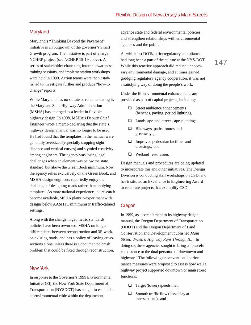
Flexible Design of New Jersey’s Main Streets
147
Maryland
Maryland’s “Thinking Beyond the Pavement”initiative is an outgrowth of the governor’s SmartGrowth program. The initiative is part of a largerNCHRP project (see NCHRP 15-19 above). Aseries of stakeholder charrettes, internal awarenesstraining sessions, and implementation workshopswere held in 1999. Action teams were then estab-lished to investigate further and produce “how-tochange” reports.
While Maryland has no statute or rule mandating it,the Maryland State Highway Administration(MSHA) has emerged as a leader in flexiblehighway design. In 1998, MSHA’s Deputy ChiefEngineer wrote a memo declaring that the state’shighway design manual was no longer to be used.He had found that the templates in the manual weregenerally oversized (especially stopping sightdistance and vertical curves) and stymied creativityamong engineers. The agency was losing legalchallenges when an element was below the statestandard, but above the Green Book minimum. Nowthe agency relies exclusively on the Green Book, andMSHA design engineers reportedly enjoy thechallenge of designing roads rather than applyingtemplates. As more national experience and researchbecome available, MSHA plans to experiment withdesigns below AASHTO minimums in traffic-calmedsettings.
Along with the change in geometric standards,policies have been reworked. MSHA no longerdifferentiates between reconstruction and 3R workon existing roads, and has a policy of leaving cross-sections alone unless there is a documented crashproblem that could be fixed through reconstruction.
New York
In response to the Governor’s 1999 EnvironmentalInitiative (EI), the New York State Department ofTransportation (NYSDOT) has sought to establishan environmental ethic within the department,
advance state and federal environmental policies,and strengthen relationships with environmentalagencies and the public.
As with most DOTs, strict regulatory compliancehad long been a part of the culture at the NYS-DOT.While this reactive approach did reduce unneces-sary environmental damage, and at times gainedgrudging regulatory agency cooperation, it was nota satisfying way of doing the people’s work.
Under the EI, environmental enhancements areprovided as part of capital projects, including:
! Street ambience enhancements(benches, paving, period lighting),
! Landscape and streetscape plantings
! Bikeways, paths, routes andgreenways,
! Improved pedestrian facilities andcrossings, and
! Wetland restoration.
Design manuals and procedures are being updatedto incorporate this and other initiatives. The DesignDivision is conducting staff workshops on CSD, andhas instituted an Excellence in Engineering Awardto celebrate projects that exemplify CSD.
Oregon
In 1999, as a complement to its highway designmanual, the Oregon Department of Transportation(ODOT) and the Oregon Department of LandConservation and Development published MainStreet…When a Highway Runs Through It…. Indoing so, these agencies sought to bring a “peacefulcoexistence to the dual personas of downtown andhighway.” The following unconventional perfor-mance measures were proposed to assess how well ahighway project supported downtown or main streetfunctions:
! Target (lower) speeds met,
! Smooth traffic flow (less delay atintersections), and

Appendix A.5
148
! Improved comfort in crossing thehighway (less pedestrian delay, lessturning delay, reduction in crashfrequency and severity).
Perhaps the most significant Oregon innovation isthe Special Transportation Area (STA) designation.Established in the Oregon Highway Plan, thisdesignation allows ODOT and local governments tojointly recognize special roadways where theinterests of local residents and businesses areweighed against the interests of through traffic. WithSTA designation comes greater flexibility in roadwaygeometrics and performance standards, both ofwhich can be tailored to a particular street.
STA-designated main streets may include:
! Signals synchronized for low speed,
! Conversion to urban cross-section(with curb & gutter),
! On-street (parallel) parking with curbextensions,
! Four to three lane conversions (up to18,000 ADT),
! Shared vehicle/bicycle lanes at speedsof 25 mph or less,
! Medians or refuge islands (minimumeight feet wide),
! Modern roundabouts,
! Intersections aligned at 90 degrees,
! Tightened or extended corners,
! Marked (high-visibility) crosswalks,and
! Gateway treatments at transitions fromopen highway to downtown.
STA-designated main streets typically exclude:
! Free right-turn lanes,
! Left-turn stacking lanes,
! Speed-change lanes, and
! Large corner radii.
A significant flaw in the STA program is that historictowns with established main streets do not derive
much benefit from the designation, and the processis a significant bureaucratic burden. Meanwhile,suburban communities have sought STA designa-tion for streets that are clearly not main streets. Forexample, one town attempted to designate a freewayinterchange and others have designated suburbanstrips.
Rhode Island
The Scenic Roadways Design Standards and ScenicRoadways Design Policy, proposed in 1996,established new standards for design speed, lanewidth, sidewalk and border widths, and bridges onscenic routes in Rhode Island. The first test casewas Ministerial Road in South Kingston, where itwas found that the new standards would notpreserve the road as desired. Consequently, the newstandards were never officially adopted.
However, long before the effort to develop newdesign standards, the Rhode Island Scenic Road-ways Board was established to:
...create & preserve rustic and scenichighways for vehicle, bicycle and pedes-trian travel... [and to protect and preserveculture & trees, et. al. by] establishingprotective standards of scenic highwaydesign, speed, maintenance...
Regarding construction, repair, or alteration ofscenic roadways, the Board has adopted ruleslimiting changes in grade, vegetation (trees), curblines, or and anything else that affects the scenicqualities of a road. The state Department of Trans-portation or municipalities may nominate any roadover which they have control for scenic designation.Six highways have been designated so far, with aseventh to be voted on soon. None of the first sixare main streets, but the seventh, State Route 114,runs through the heart of Bristol’s downtownHistoric District as Hope Street.
Hope Street is characterized by unbroken allees ofmature Linden trees growing in large green bufferzones. It has sidewalks set far back from the curb,

Flexible Design of New Jersey’s Main Streets
149
and several historic buildings and stone walls alongit. The broad right-of-way is part of the town planlaid out in 1680.
Vermont
Over the past ten years, the Vermont Agency ofTransportation (VAOT) has undertaken three relatedflexible design initiatives. Two were procedural:establishment of a Project Definition Team to settleconflicts in the planning, scoping, and projectdevelopment, before projects are engineered; andreorganization of the agency to a project manager-based system. The third initiative was the develop-ment of new design standards for non-NHS routes.Vermont’s new design standards were an outgrowthof the long-range planning process required byISTEA. As part of that process, VAOT found thatroads built using the AASHTO Green Book guide-lines were sometimes out of context and inconsis-tent with community values; many projects requireddesign exceptions or were scuttled due to commu-nity opposition.
In response, the Vermont Legislature ordered VAOTto develop standards more appropriate to Vermont.The new standards relate to design speed, LOS,travel lane width, clear zone, stopping sight dis-tance, horizontal curvature, and grade. BecauseVermont is the only state to largely rewrite its designstandards pursuant to ISTEA, it is instructive toconsider the timeline. It took five years to getagreement on sub-AASHTO standards.
Two items of note have followed Vermont’s newroadway standards. The first is an intergovernmentalagreement with FHWA giving VAOT the power togrant its own design exceptions on all highwaysexcept Interstates. While state standards for NHSroutes are within Green Book guidelines, having theauthority to grant design exceptions has causedVAOT to be particularly flexible and responsive.
The second concerns the classification of urban andrural roadways. The Green Book adopts the censusdefinition of “urban place.” Many towns in Vermont
have smaller populations, but are nonetheless builtup. VAOT has taken the position that a road’sclassification should be based on the surroundingbuilt form, not population or population density. Bychanging the classification from rural to urban, theagency has greater flexibility with design elementssuch as roadside clearance, curbs, and shoulderwidth.
Washington
The current Washington State Transportation Plancalls for “Livable Communities.” What that entails isnot defined. To address this shortcoming, theWashington State Transportation Commissionrecently asked a statewide working group to draftrecommendations. The group consisted of represen-tatives from the Washington Department of Trans-portation (WSDOT), environmental advocates,mayors, the National Highway Traffic SafetyAdministration, transit agencies, and others.
The group arrived at a series of strategies to achievelivability, some of which affect main street design:
! Preserve existing corridors, both urban& rural,
! Be flexible in design standards andprocedures,
! Define community values duringplanning and design,
! Enhance scenic views, neighborhoods,and historic districts, and
! Provide focal points along roadways—such as plazas.
To ensure that these strategies are carried out byWSDOT, the working group recommended that theagency:
! Survey communities every two yearsto assess their level of satisfactionwith projects,
! Start project outreach and coordina-tion four to six years prior to construc-tion, and

Appendix A.5
150
! Seek alternative funding sources forlivable community projects.
The last point is especially pertinent, for fundingalways influences an agency’s ability to respond tocommunity needs. WSDOT wants its livabilityinitiative to be successful, yet strategic and appro-priate. To that end the Livable CommunitiesInitiative will provide early notification aboutprojects to communities, help them develop a livablecommunity plan, and work with them to findadditional funding for amenities.
References
1. Flexibility in Highway Design, FHWA, 1997.
2. Context Sensitive Design for IntegratingHighway and Street Projects with Communities andthe Environment. Chapter 1: Project DevelopmentProcess. NCHRP 20-17-114, final draft, Feb. 2000.
3. AASHTO Guide for the Planning, Design andOperation of Pedestrian Facilities. NCHRP 20-07-105, unreleased.
4. Connecticut Public Act # 98-118, revised 1998.
5. Traffic Calming Design Manual. DelawareDepartment of Transportation, 2000.
6. Transportation Design for Livable Communi-ties. FL-DOT Directive 525-030-301-a, 1999.
7. Sensible Transportation Policy Act. Maine Rev.Stat. Ann. Title 23, Section 73, revised 1994.
8. Thinking Beyond the Pavement. MSHA,undated.
9. “NYS-DOT Environmental Initiative Guide-lines and Procedures for a New Paradigm.” GaryMcVoy, et al, NY-DOT Environmental AnalysisBureau, undated.
10. Main Street…When a Highway Runs ThroughIt: A Handbook for Oregon Communities. OregonDepartments of Transportation and Land Conserva-tion & Development, 1999.
11. Rules of the Rhode Island Scenic RoadwaysBoard, revised 1999.
12. “Development of Vermont’s State Standards forRoadway Design”, Bruce Bender, VT-AOT,undated.
13. “Livable Communities Initiative.” WA-DOT,undated.

Flexible Design of New Jersey’s Main Streets
151
Appendix A.6
Summary ofDesignExceptions1997-1999
For this project, the TPI team reviewedeighty-one design exception reportsfiled between 1997 and 1999. Of the eighty-
one, fifty reports were found to have given someconsideration to community, historical, or environ-mental factors.
! Several projects required designexceptions to keep 3R projects frombecoming full reconstruction projects,with greater attendant communityimpacts.
! Several projects in village or suburbansettings required design exceptions, inpart, to lessen community, historic, orenvironmental impacts.
! Several bridge replacement projectsrequired design exceptions, in part, tolessen community, historic, or environ-mental impacts.
This record is less impressive than it at first appears.Of the eighty-one design exceptions, eighty appearto be driven primarily by cost savings. In only onecase, involving historic preservation in Oxford, NewJersey, was the driving force context savings. Inother cases, community, historic, or environmentalfactors appeared to be somewhat incidental to thedesign exception.
The 3R projects involved an odd catch-22. Thetypical 3R project fails to qualify for a program-matic design exception, and therefore requires lanewidening, shoulder widening, or some otherimprovement in cross section or alignment to meet
current design standards. With such an improve-ment, the project is automatically reclassified as afull reconstruction project. So the design engineerseeks one or more regular design exceptions to keepthe 3R project what it was always intended to be, a3R project.
The bridge projects involve such substantial outlaysin most cases that construction costs overwhelm allother factors. In fact, bridges themselves seldomhave direct impacts on the communities they serve,as they span water, other highways, rail lines, etc. Itis only through their relationship to adjacenthighways, and the need for smooth transitions fromone to the other, that bridges may have such animpact. In the typical case, a substandard shoulderor lane width is approved on a bridge to avoid theexpense of widening to the full width of the adjacentroadway.
For the fifty projects giving some consideration tocommunity, historic, or environmental factors, TableA.6.1 shows the type and frequency of designexceptions approved. The table after that providesdetails on each project requiring design exceptions.
Table A.6.1: Type and frequency of designexceptions.
Number ofCSDE Projects
Shoulder Width 20Vertical Curve SSD 16Superelevation 13Horizontal Curve Radius 12Vertical Clearance 7Auxiliary Lane Length 6Travel Lane Width 5Bridge Width 4Horizontal Curve SSD 3Intersection Sight Distance 2Grade 1Cross Slope 0

Appendix A.6
152
Note the preponderance of cases with one of fourControlling Substandard Design Elements (CSDEs):vertical stopping sight distance, horizontal curveradius, shoulder width, or superelevation. Theseparticular design elements are ordinarily not aproblem on main streets, with the possible exceptionof substandard width of shoulders which, arguably,
should not be required on main streets anyway. Thatthese particular CSDEs are so overrepresented indesign exception cases, and other CSDEs such assubstandard lane width are so under-represented,indicates that design exceptions are either notrequired or not sought very often in main streetprojects.
LandProject County NHS Project Type Highway Class CSDEs Cost Use Hist Env Notes
Washington Somerset No Bridge Rural Minor Shoulder Width X X X HistoricAvenue Replacement Collector District,Bridge SHPO
involve-ment
Mountain Somerset No Bridge Rural Shoulder Width X X X Consider-Replacement Undivided ation of
Local Road historicstructures
Route 29 at Mercer Yes Reconstruction Urban Vertical SSD, X XParkside Av. Freeway Horizontal SSD,
Superelevation,Horizontal CurveRadius, Vertical
Clearance, AuxiliaryLane Length
Greentree Glouchester No Reconstruction Superelevation X XRoad, Sec. 2
Rt 183 Sussex No Reconstruction Urban Curve Radius, X X XSec 1B Undivided Intersection
Principal Sight DistanceArterial
Route 47 Gloucester No Reconstruction Rural Shoulder Width X X X X Design(Section 9) Principal exception to
Arterial minimizeimpact onbuilding
eligible forNational
Register forHistoricPlaces
Route 47 Cumberland No Resurfacing Rural Shoulder Width, X XSection 5D & Cape May Horizontal Curve& 6B Radius
Maple Ave. Camden No Reconstruction Minor Vertical Clearance X XBridge over Urban Arterial over RRNJ Transit
Kinnaman Warren No Bridge Undivided Sag VCCrest VC X X X XAvenue Replacement Rural MajorBridge Collector
Sussex Sussex No Bridge Undivided Vertical SSD X XCounty Replacement Rural RoadBridge J-05
Table A.6.2: Details on Design Exception Cases 1997-1999

Flexible Design of New Jersey’s Main Streets
153
Table A.6.2: Details on Design Exception Cases 1997-1999
LandProject County NHS Project Type Highway Class CSDEs Cost Use Hist Env Notes
Sussex Sussex No Bridge Local Rural Vertical SSD, X X XCounty Replacement Road Horizontal CurveBridge O-08 Radius, Intersection
Sight Distance
Maple Sussex No Bridge Rural Lane Width, X XGrange Road Replacement Shoulder Width,Bridge Superelevation
Route 563, Sussex No Bridge Rural Major Bridge Width, X XGreen Bank Replacement Collector Lane Width,Road Bridge Shoulder Width
Route 206 Sussex Yes Reconstruction Undivided Bridge Width, X X X& 15 Ross's Rural Vertical SSD,Corner Road Principal Shoulder Width
Arterial
Belford Monmouth No Bridge Urban Vertical SSD X X XProject Replacement
Tuckahoe Cape May No Resurfacing Rural Lane Width, X XRoad (CR Shoulder Width631)
Ocean Atlantic No Resurfacing Urban Shoulder Width, X X XHeights Av. Minor Arterial Vertical SSD(CR 559 Alt.)Phase 1
Ocean Atlantic No Resurfacing Urban Shoulder Width X XHeights Av. Minor Arterial(CR 559 Alt)Phase 2
Zion Road Atlantic No Resurfacing Rural Shoulder Width X X X(CR 615)
Straight St. Passaic No Bridge Urban Horizontal Curve X X XBridge Replacement Radius
Route 7, Essex/ No Bridge Urban Superelevation, X X XSection 1AG Hudson Replacement Principal Vertical SSD,
Arterial Shoulder Width
Old Texas Middlesex No Bridge Minor Arterial Superelevation X XRoad Bridge Replacement
Ocean Drive, Cape May/ No Bridge Minor Urban Horizontal Curve X XOcean City Atlantic Replacement Arterial Radius
Mt. Pleasant Essex No Bridge Urban Local Bridge Width, X XPlace Bridge Replacement Road Vertical SSD
Route 88 @ Ocean No Reconstruction Urban Minor Lane Width X X WidthsClifton Ave. Arterial minimized
to reduceimpacts onnew brickpavement
Route 15, Sussex No Reconstruction Rural Horizontal Curve X XSection 4C Principal Radius, Grade,
Arterial Vertical SSD

Appendix A.6
154
LandProject County NHS Project Type Highway Class CSDEs Cost Use Hist Env Notes
Route 1&9 Bergen Yes New Construction/ Urban Horizontal Curve X X CBD area.(27) Ridge- Reconstruction Radius,field Circle Shoulder WidthElimination
Route 31 Hunterdon Yes New Construction/ Rural Principal Horizontal SSD X X XSections 6B Reconstruction Arterial& 7E
Black River Somerset No Bridge Rural Superelevation X X X XRoad Bridge Replacement
Route 71 @ Monmouth No Reconstruction Urban Minor Shoulder Width X XWall Street Arterial
Route 202, Somerset No Reconstruction Urban Minor Vertical SSD, X X DesignBernards- Arterial Superelevation exceptionsville avoided
need toreconstructdriveways
Route 166 Ocean No Resurfacing Urban Shoulder Width, X X Tom's RiverBoroughs Lane Width CBD areaof Beech- Designwood & S. exceptionsTom’s River avoided
need forextensive
reconstruc-tion and
removal ofexisting
trees
Route 124 Morris No Resurfacing Urban Horizontal Curve X X DesignSection 1 Radius, Vertical SSD, exceptionsBoroughs of Vertical Clearance, to minimizeMadison Bridge Width impacts on& Chatham Madison
CBD
Route 23 Sussex No Reconstruction Rural Principal Vertical SSD, X XSection 7D Arterial Superelevation& Route 94Section 8C
U.S. Route Somerset No Reconstruction Rural Curve Radius X X202/206 at Jughandle,
Auxiliary LaneLength
Route 9, Middlesex No Bridge Urban Principal Horizontal Curve X XSec 25K & Replacement Arterial Radius1F, Boroughof Sayreville
Interstate Mercer Yes Reconstruction Interstate/ Vertical SSD, X X X X95/Route 31 Urban Principal Auxiliary LaneInterchange Arterial Length
Table A.6.2: Details on Design Exception Cases 1997-1999
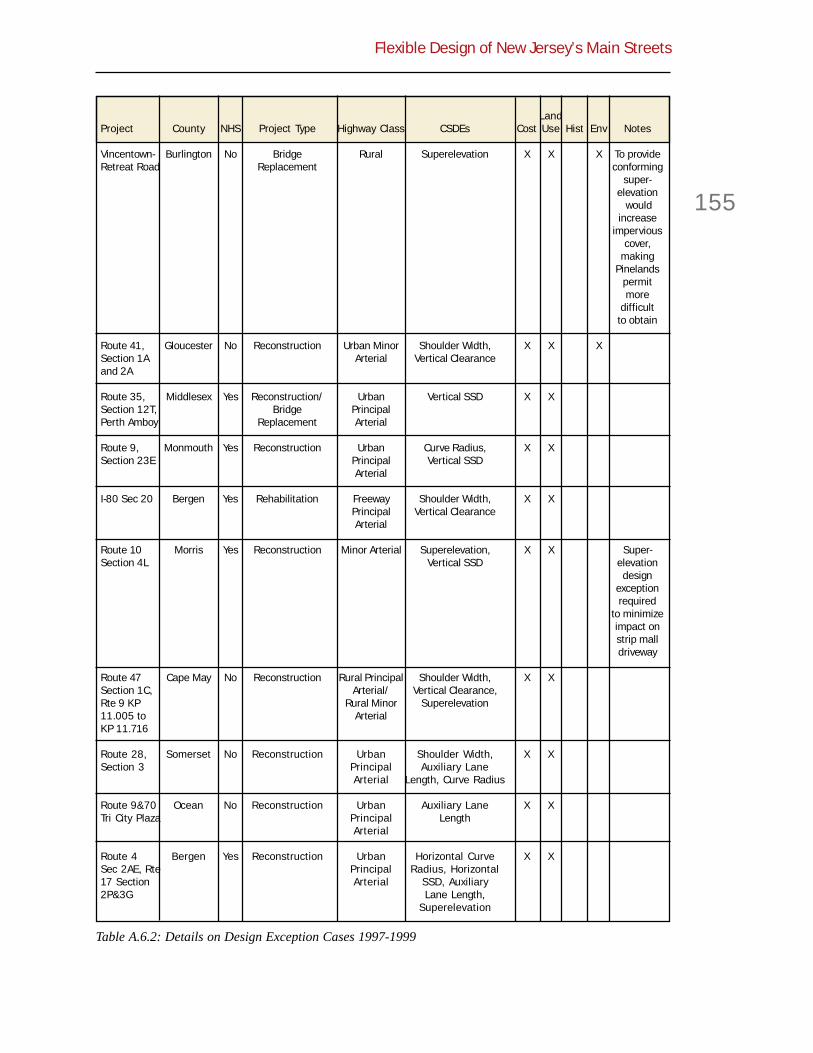
Flexible Design of New Jersey’s Main Streets
155
Table A.6.2: Details on Design Exception Cases 1997-1999
LandProject County NHS Project Type Highway Class CSDEs Cost Use Hist Env Notes
Vincentown- Burlington No Bridge Rural Superelevation X X X To provideRetreat Road Replacement conforming
super-elevation
wouldincrease
imperviouscover,
makingPinelands
permitmore
difficultto obtain
Route 41, Gloucester No Reconstruction Urban Minor Shoulder Width, X X XSection 1A Arterial Vertical Clearanceand 2A
Route 35, Middlesex Yes Reconstruction/ Urban Vertical SSD X XSection 12T, Bridge PrincipalPerth Amboy Replacement Arterial
Route 9, Monmouth Yes Reconstruction Urban Curve Radius, X XSection 23E Principal Vertical SSD
Arterial
I-80 Sec 20 Bergen Yes Rehabilitation Freeway Shoulder Width, X XPrincipal Vertical ClearanceArterial
Route 10 Morris Yes Reconstruction Minor Arterial Superelevation, X X Super-Section 4L Vertical SSD elevation
designexceptionrequired
to minimizeimpact onstrip malldriveway
Route 47 Cape May No Reconstruction Rural Principal Shoulder Width, X XSection 1C, Arterial/ Vertical Clearance,Rte 9 KP Rural Minor Superelevation11.005 to ArterialKP 11.716
Route 28, Somerset No Reconstruction Urban Shoulder Width, X XSection 3 Principal Auxiliary Lane
Arterial Length, Curve Radius
Route 9&70 Ocean No Reconstruction Urban Auxiliary Lane X XTri City Plaza Principal Length
Arterial
Route 4 Bergen Yes Reconstruction Urban Horizontal Curve X XSec 2AE, Rte Principal Radius, Horizontal17 Section Arterial SSD, Auxiliary2P&3G Lane Length,
Superelevation

Appendix A.6
156
Table A.6.2: Details on Design Exception Cases 1997-1999
Project County NHS Project Type Highway Class CSDEs Cost Use Hist Env Notes
Route U.S. Middlesex Yes Reconstruction Urban Vertical Clearance, X X1, Section Principal Shoulder Width6T, Route US Arterial130, Section16B, Route171, Section1B
Route 17 Bergen Yes Reconstruction Urban Horizontal Curve X XSection 3H, Principal Radius,5AE Arterial Superelevation
Route 17(3) Bergen Yes Reconstruction Urban Horizontal Curve X XPrincipal RadiusArterial

Flexible Design of New Jersey’s Main Streets
ii
Voorhees Transportation Policy InstituteEdward J. Bloustein School of Planning and Public Policy
Rutgers, The State University of New Jersey


