
Flexi Soft Driver - hmisource.com Soft Driver GP-Pro EX Device/PLC Connection Manual 6 2 External...
24
1 SICK AG Flexi Soft Driver 1 System Configuration ....................................................................................................... 3 2 External Device Selection ................................................................................................ 6 3 Communication Settings .................................................................................................. 7 4 Setup Items ...................................................................................................................... 9 5 Cable Diagrams ............................................................................................................. 15 6 Supported Device........................................................................................................... 17 7 Device Code and Address Code .................................................................................... 22 8 Error Messages .............................................................................................................. 23
Transcript of Flexi Soft Driver - hmisource.com Soft Driver GP-Pro EX Device/PLC Connection Manual 6 2 External...
1
SICK AG
Flexi Soft Driver
1 System Configuration....................................................................................................... 3
2 External Device Selection ................................................................................................ 6
3 Communication Settings .................................................................................................. 7
4 Setup Items ...................................................................................................................... 9
5 Cable Diagrams ............................................................................................................. 15
6 Supported Device........................................................................................................... 17
7 Device Code and Address Code.................................................................................... 22
8 Error Messages.............................................................................................................. 23
Flexi Soft Driver
GP-Pro EX Device/PLC Connection Manual 2
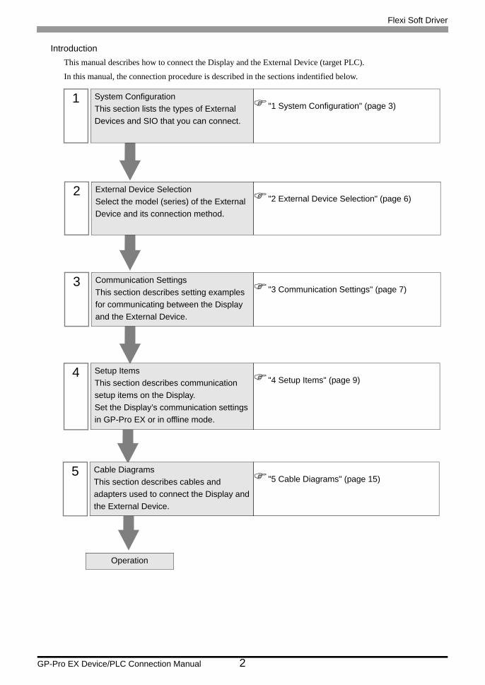
IntroductionThis manual describes how to connect the Display and the External Device (target PLC).
In this manual, the connection procedure is described in the sections indentified below.
1 System ConfigurationThis section lists the types of External Devices and SIO that you can connect.
"1 System Configuration" (page 3)
2 External Device SelectionSelect the model (series) of the External Device and its connection method.
"2 External Device Selection" (page 6)
3 Communication SettingsThis section describes setting examples for communicating between the Display and the External Device.
"3 Communication Settings" (page 7)
4 Setup ItemsThis section describes communication setup items on the Display.Set the Display’s communication settings in GP-Pro EX or in offline mode.
"4 Setup Items" (page 9)
5 Cable DiagramsThis section describes cables and adapters used to connect the Display and the External Device.
"5 Cable Diagrams" (page 15)
Operation
Flexi Soft Driver
GP-Pro EX Device/PLC Connection Manual 3
1 System Configuration
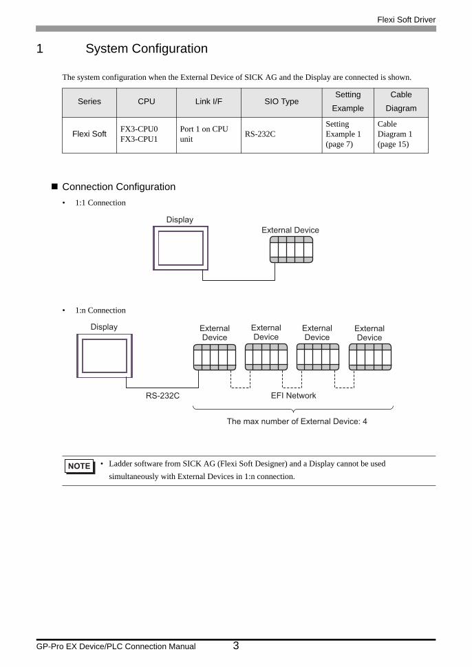
The system configuration when the External Device of SICK AG and the Display are connected is shown.
Connection Configuration• 1:1 Connection
• 1:n Connection
Series CPU Link I/F SIO TypeSetting
Example
Cable
Diagram
Flexi Soft FX3-CPU0FX3-CPU1
Port 1 on CPU unit RS-232C
Setting Example 1 (page 7)
Cable Diagram 1 (page 15)
• Ladder software from SICK AG (Flexi Soft Designer) and a Display cannot be used simultaneously with External Devices in 1:n connection.
DisplayExternal Device
RS-232C EFI Network
The max number of External Device: 4
Display ExternalDevice
ExternalDevice
ExternalDevice
ExternalDevice
Flexi Soft Driver
GP-Pro EX Device/PLC Connection Manual 4
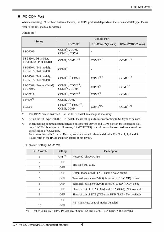
IPC COM PortWhen connecting IPC with an External Device, the COM port used depends on the series and SIO type. Please
refer to the IPC manual for details.
Usable port
DIP Switch setting: RS-232C
SeriesUsable Port
RS-232C RS-422/485(4 wire) RS-422/485(2 wire)
PS-2000B COM1*1 , COM2, COM3*1, COM4
*1 The RI/5V can be switched. Use the IPC’s switch to change if necessary.
- -
PS-3450A, PS-3451A,PS3000-BA, PS3001-BD COM1, COM2*1*2 COM2*1*2 COM2*1*2
PS-3650A (T41 model),PS-3651A (T41 model) COM1*1 - -
PS-3650A (T42 model),PS-3651A (T42 model) COM1*1*2, COM2 COM1*1*2 COM1*1*2
PS-3700A (Pentium®4-M)PS-3710A
COM1*1, COM2*1, COM3*2 , COM4
*2 Set up the SIO type with the DIP Switch. Please set up as follows according to SIO type to be used.
COM3*2 COM3*2
PS-3711A COM1*1, COM2*2 COM2*2 COM2*2
PS4000*3
*3 When making communication between an External Device and COM port on the Expansion slot,only RS-232C is supported. However, ER (DTR/CTS) control cannot be executed because of thespecification of COM port.For connection with External Device, use user-created cables and disable Pin Nos. 1, 4, 6 and 9.Please refer to the IPC manual for details of pin layout.
COM1, COM2 - -
PL3000 COM1*1*2, COM2*1, COM3, COM4 COM1*1*2 COM1*1*2
DIP Switch Setting Description
1 OFF*1
*1 When using PS-3450A, PS-3451A, PS3000-BA and PS3001-BD, turn ON the set value.
Reserved (always OFF)
2 OFFSIO type: RS-232C
3 OFF
4 OFF Output mode of SD (TXD) data: Always output
5 OFF Terminal resistance (220Ω) insertion to SD (TXD): None
6 OFF Terminal resistance (220Ω) insertion to RD (RXD): None
7 OFF Short-circuit of SDA (TXA) and RDA (RXA): Not available
8 OFF Short-circuit of SDB (TXB) and RDB (RXB): Not available
9 OFFRS (RTS) Auto control mode: Disabled
10 OFF
Flexi Soft Driver
GP-Pro EX Device/PLC Connection Manual 5
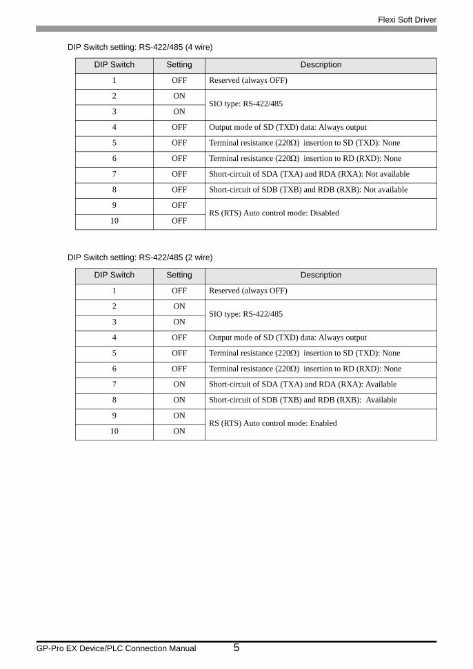
DIP Switch setting: RS-422/485 (4 wire)
DIP Switch setting: RS-422/485 (2 wire)
DIP Switch Setting Description
1 OFF Reserved (always OFF)
2 ONSIO type: RS-422/485
3 ON
4 OFF Output mode of SD (TXD) data: Always output
5 OFF Terminal resistance (220Ω) insertion to SD (TXD): None
6 OFF Terminal resistance (220Ω) insertion to RD (RXD): None
7 OFF Short-circuit of SDA (TXA) and RDA (RXA): Not available
8 OFF Short-circuit of SDB (TXB) and RDB (RXB): Not available
9 OFFRS (RTS) Auto control mode: Disabled
10 OFF
DIP Switch Setting Description
1 OFF Reserved (always OFF)
2 ONSIO type: RS-422/485
3 ON
4 OFF Output mode of SD (TXD) data: Always output
5 OFF Terminal resistance (220Ω) insertion to SD (TXD): None
6 OFF Terminal resistance (220Ω) insertion to RD (RXD): None
7 ON Short-circuit of SDA (TXA) and RDA (RXA): Available
8 ON Short-circuit of SDB (TXB) and RDB (RXB): Available
9 ONRS (RTS) Auto control mode: Enabled
10 ON
Flexi Soft Driver
GP-Pro EX Device/PLC Connection Manual 6
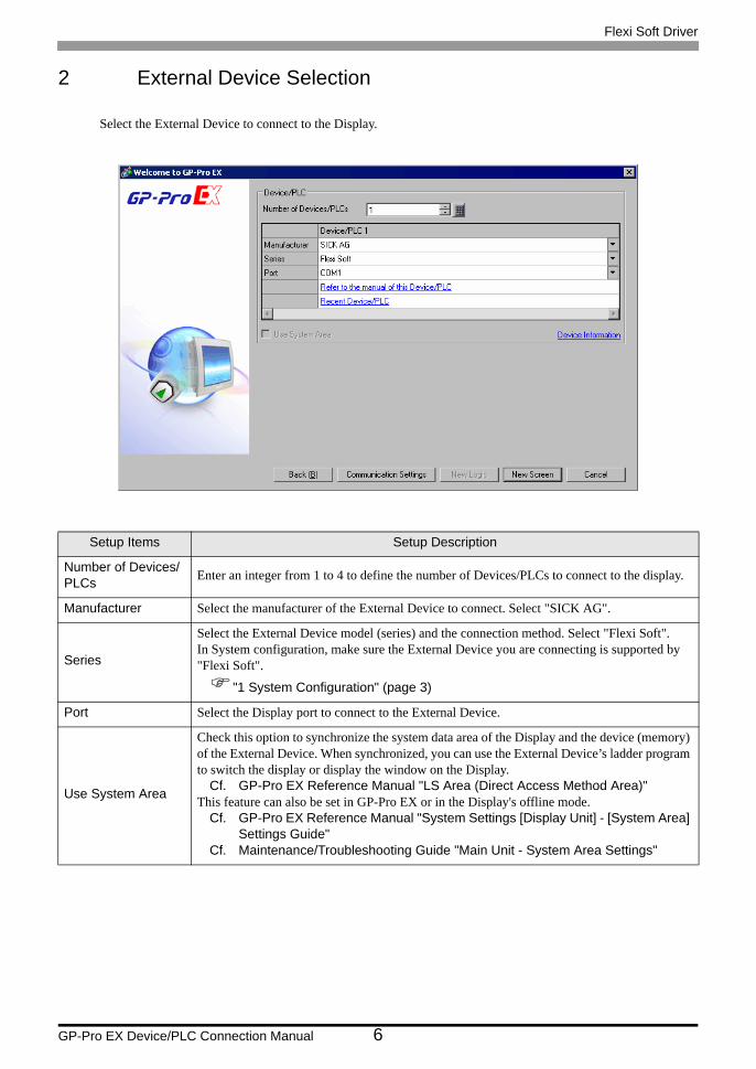
2 External Device Selection
Select the External Device to connect to the Display.
Setup Items Setup Description
Number of Devices/PLCs Enter an integer from 1 to 4 to define the number of Devices/PLCs to connect to the display.
Manufacturer Select the manufacturer of the External Device to connect. Select "SICK AG".
Series
Select the External Device model (series) and the connection method. Select "Flexi Soft".In System configuration, make sure the External Device you are connecting is supported by "Flexi Soft".
"1 System Configuration" (page 3)
Port Select the Display port to connect to the External Device.
Use System Area
Check this option to synchronize the system data area of the Display and the device (memory) of the External Device. When synchronized, you can use the External Device’s ladder program to switch the display or display the window on the Display.
Cf. GP-Pro EX Reference Manual "LS Area (Direct Access Method Area)"This feature can also be set in GP-Pro EX or in the Display's offline mode.
Cf. GP-Pro EX Reference Manual "System Settings [Display Unit] - [System Area] Settings Guide"
Cf. Maintenance/Troubleshooting Guide "Main Unit - System Area Settings"
Flexi Soft Driver
GP-Pro EX Device/PLC Connection Manual 7
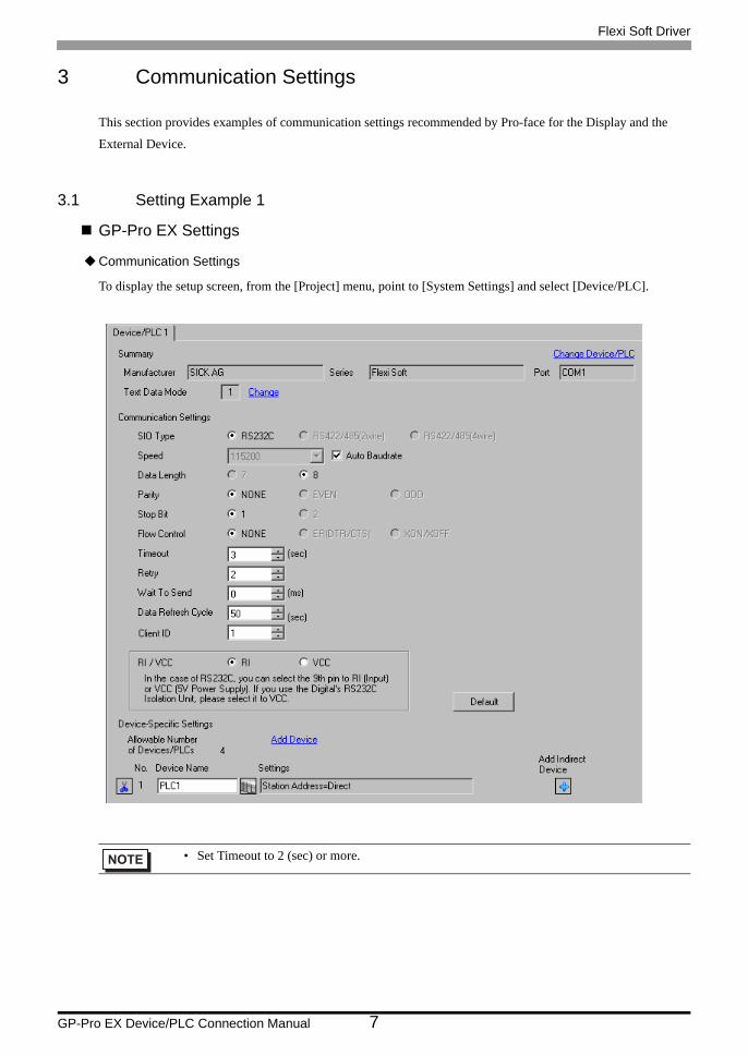
3 Communication Settings
This section provides examples of communication settings recommended by Pro-face for the Display and the
External Device.
3.1 Setting Example 1
GP-Pro EX Settings
Communication Settings
To display the setup screen, from the [Project] menu, point to [System Settings] and select [Device/PLC].
• Set Timeout to 2 (sec) or more.
Flexi Soft Driver
GP-Pro EX Device/PLC Connection Manual 8
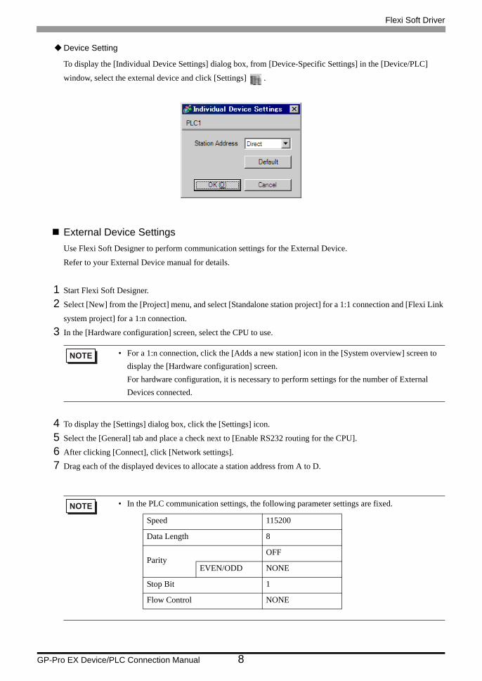
Device Setting
To display the [Individual Device Settings] dialog box, from [Device-Specific Settings] in the [Device/PLC]
window, select the external device and click [Settings] .
External Device SettingsUse Flexi Soft Designer to perform communication settings for the External Device.
Refer to your External Device manual for details.
1 Start Flexi Soft Designer.
2 Select [New] from the [Project] menu, and select [Standalone station project] for a 1:1 connection and [Flexi Link
system project] for a 1:n connection.
3 In the [Hardware configuration] screen, select the CPU to use.
4 To display the [Settings] dialog box, click the [Settings] icon.
5 Select the [General] tab and place a check next to [Enable RS232 routing for the CPU].
6 After clicking [Connect], click [Network settings].
7 Drag each of the displayed devices to allocate a station address from A to D.
• For a 1:n connection, click the [Adds a new station] icon in the [System overview] screen to display the [Hardware configuration] screen.For hardware configuration, it is necessary to perform settings for the number of External Devices connected.
• In the PLC communication settings, the following parameter settings are fixed.
Speed 115200
Data Length 8
ParityOFF
EVEN/ODD NONE
Stop Bit 1
Flow Control NONE
Flexi Soft Driver
GP-Pro EX Device/PLC Connection Manual 9
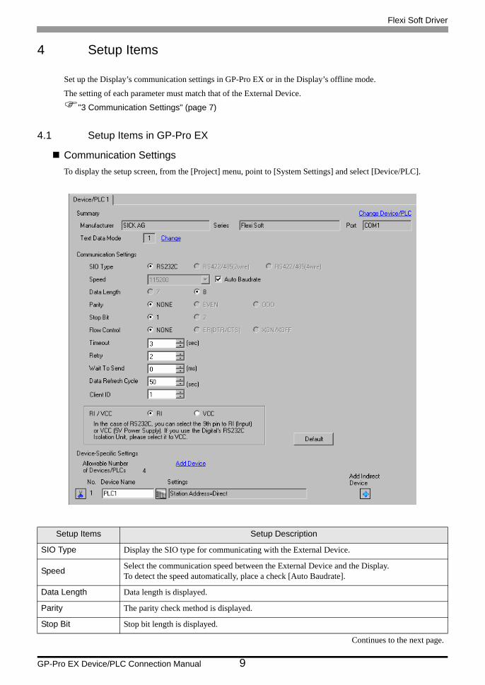
4 Setup Items
Set up the Display’s communication settings in GP-Pro EX or in the Display’s offline mode.
The setting of each parameter must match that of the External Device.
"3 Communication Settings" (page 7)
4.1 Setup Items in GP-Pro EX
Communication SettingsTo display the setup screen, from the [Project] menu, point to [System Settings] and select [Device/PLC].
Setup Items Setup Description
SIO Type Display the SIO type for communicating with the External Device.
Speed Select the communication speed between the External Device and the Display.To detect the speed automatically, place a check [Auto Baudrate].
Data Length Data length is displayed.
Parity The parity check method is displayed.
Stop Bit Stop bit length is displayed.
Continues to the next page.
Flexi Soft Driver
GP-Pro EX Device/PLC Connection Manual 10
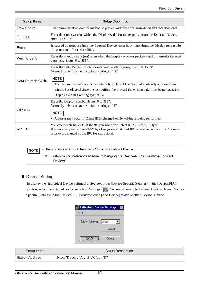
Device SettingTo display the [Individual Device Settings] dialog box, from [Device-Specific Settings] in the [Device/PLC]
window, select the external device and click [Settings] . To connect multiple External Devices, from [Device-
Specific Settings] in the [Device/PLC] window, click [Add Device] to add another External Device.
Flow Control The communication control method to prevent overflow of transmission and reception data.
Timeout Enter the time (sec) for which the Display waits for the response from the External Device, from "1 to 127".
Retry In case of no response from the External Device, enter how many times the Display retransmits the command, from "0 to 255".
Wait To Send Enter the standby time (ms) from when the Display receives packets until it transmits the next command, from "0 to 255".
Data Refresh Cycle
Enter the Data Refresh Cycle for retaining written values, from "10 to 59".Normally, this is set at the default setting of "50".
• The External Device resets the data in RS-232 to Flexi Soft automatically as soon as one minute has elapsed since the last writing. To prevent the written data from being reset, the Display executes writing cyclically.
Client ID
Enter the Display number, from "0 to 255".Normally, this is set at the default setting of "1".
• An error may occur if Client ID is changed while writing is being performed.
RI/VCCYou can switch RI/VCC of the 9th pin when you select RS232C for SIO type.It is necessary to change RI/5V by changeover switch of IPC when connect with IPC. Please refer to the manual of the IPC for more detail.
• Refer to the GP-Pro EX Reference Manual for Indirect Device.
Cf. GP-Pro EX Reference Manual "Changing the Device/PLC at Runtime (Indirect Device)"
Setup Items Setup Description
Station Address Select "Direct", "A", "B","C", or "D".
Setup Items Setup Description
Flexi Soft Driver
GP-Pro EX Device/PLC Connection Manual 11
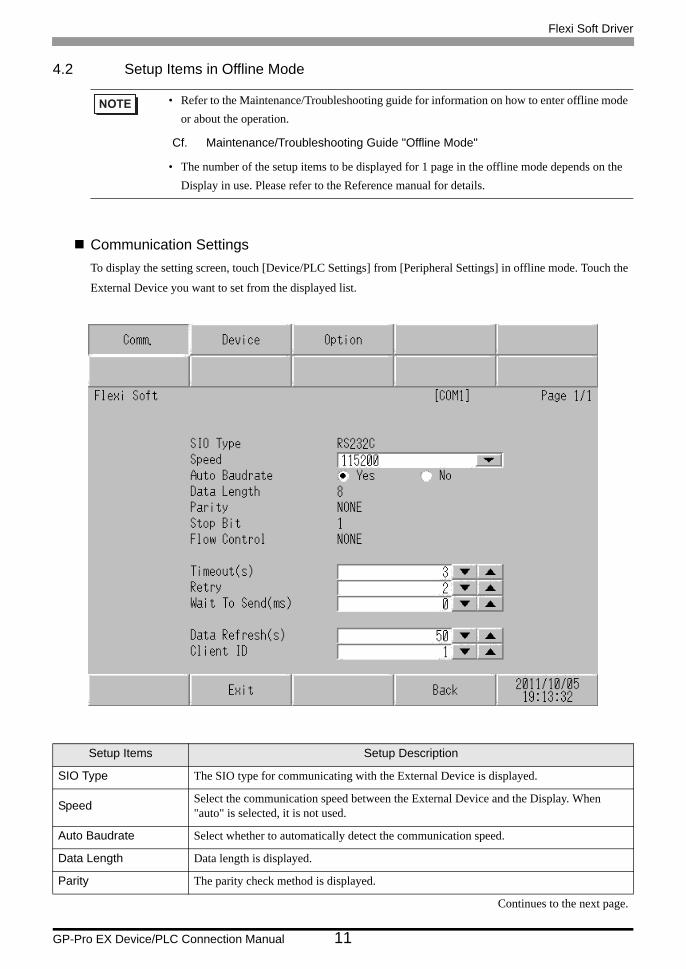
4.2 Setup Items in Offline Mode
Communication SettingsTo display the setting screen, touch [Device/PLC Settings] from [Peripheral Settings] in offline mode. Touch the
External Device you want to set from the displayed list.
• Refer to the Maintenance/Troubleshooting guide for information on how to enter offline mode or about the operation.
Cf. Maintenance/Troubleshooting Guide "Offline Mode"
• The number of the setup items to be displayed for 1 page in the offline mode depends on the Display in use. Please refer to the Reference manual for details.
Setup Items Setup Description
SIO Type The SIO type for communicating with the External Device is displayed.
Speed Select the communication speed between the External Device and the Display. When "auto" is selected, it is not used.
Auto Baudrate Select whether to automatically detect the communication speed.
Data Length Data length is displayed.
Parity The parity check method is displayed.
Continues to the next page.
Flexi Soft Driver
GP-Pro EX Device/PLC Connection Manual 12
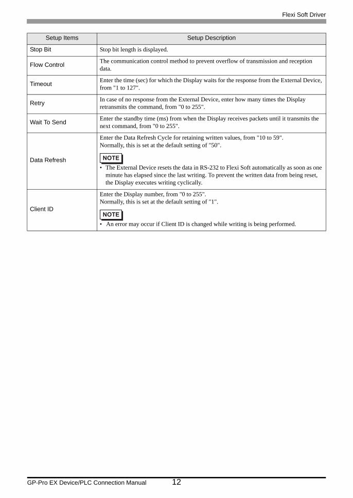
Stop Bit Stop bit length is displayed.
Flow Control The communication control method to prevent overflow of transmission and reception data.
Timeout Enter the time (sec) for which the Display waits for the response from the External Device, from "1 to 127".
Retry In case of no response from the External Device, enter how many times the Display retransmits the command, from "0 to 255".
Wait To Send Enter the standby time (ms) from when the Display receives packets until it transmits the next command, from "0 to 255".
Data Refresh
Enter the Data Refresh Cycle for retaining written values, from "10 to 59".Normally, this is set at the default setting of "50".
• The External Device resets the data in RS-232 to Flexi Soft automatically as soon as one minute has elapsed since the last writing. To prevent the written data from being reset, the Display executes writing cyclically.
Client ID
Enter the Display number, from "0 to 255".Normally, this is set at the default setting of "1".
• An error may occur if Client ID is changed while writing is being performed.
Setup Items Setup Description
Flexi Soft Driver
GP-Pro EX Device/PLC Connection Manual 13
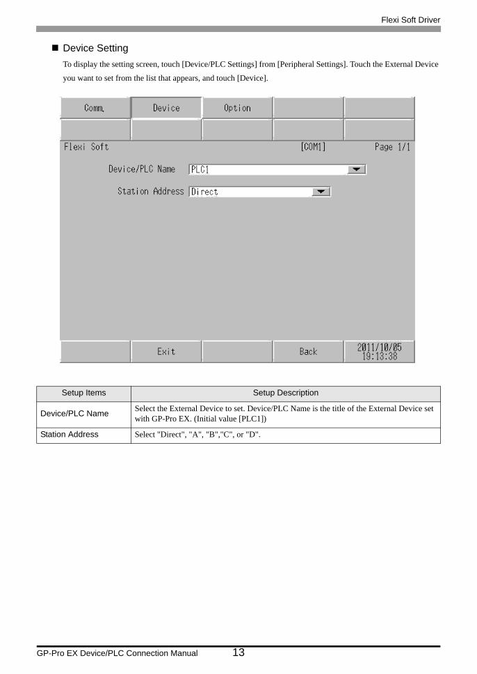
Device SettingTo display the setting screen, touch [Device/PLC Settings] from [Peripheral Settings]. Touch the External Device
you want to set from the list that appears, and touch [Device].
Setup Items Setup Description
Device/PLC Name Select the External Device to set. Device/PLC Name is the title of the External Device set with GP-Pro EX. (Initial value [PLC1])
Station Address Select "Direct", "A", "B","C", or "D".
Flexi Soft Driver
GP-Pro EX Device/PLC Connection Manual 14
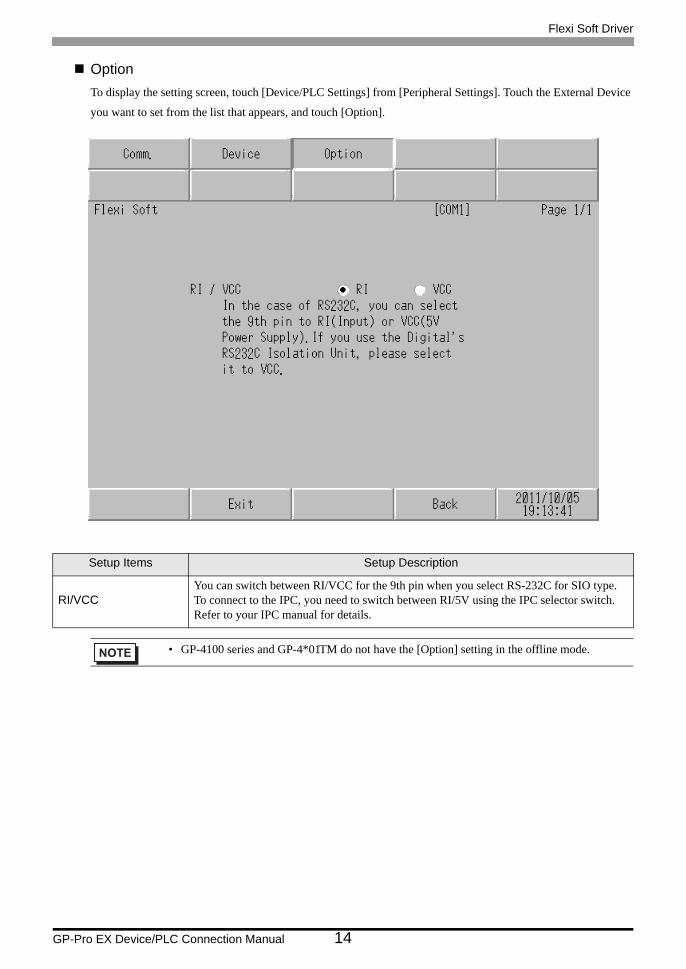
OptionTo display the setting screen, touch [Device/PLC Settings] from [Peripheral Settings]. Touch the External Device
you want to set from the list that appears, and touch [Option].
Setup Items Setup Description
RI/VCCYou can switch between RI/VCC for the 9th pin when you select RS-232C for SIO type.To connect to the IPC, you need to switch between RI/5V using the IPC selector switch. Refer to your IPC manual for details.
• GP-4100 series and GP-4*01TM do not have the [Option] setting in the offline mode.
Flexi Soft Driver
GP-Pro EX Device/PLC Connection Manual 15
5 Cable Diagrams
The cable diagrams shown below may be different from the cable diagrams recommended by SICK AG. Please be
assured there is no operational problem in applying the cable diagrams shown in this manual.
• The FG pin on the External Device must be D-class grounded. Refer to your External Device manual for
details.
• The SG and FG are connected inside the Display. If you connect the External Device to the SG, do not form
any short-circuit loop in the system design.
• If the communication is not stable because of noise or other factors, connect an isolation unit.
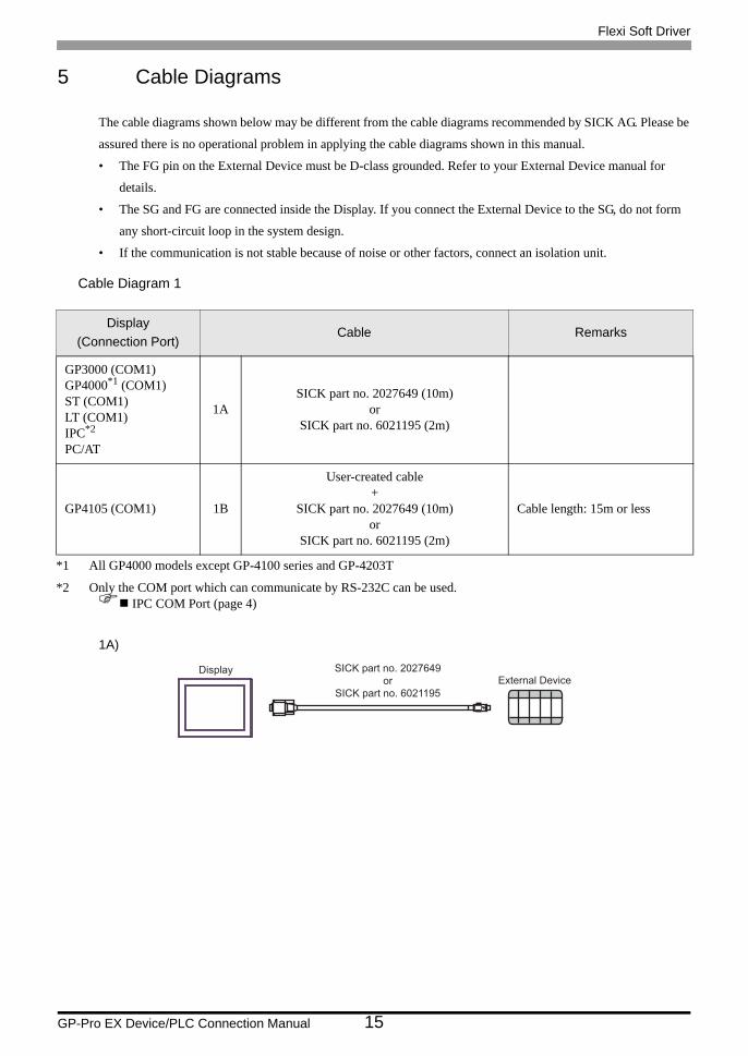
Cable Diagram 1
1A)
Display(Connection Port)
Cable Remarks
GP3000 (COM1)GP4000*1 (COM1)ST (COM1)LT (COM1)IPC*2
PC/AT
*1 All GP4000 models except GP-4100 series and GP-4203T
*2 Only the COM port which can communicate by RS-232C can be used. IPC COM Port (page 4)
1ASICK part no. 2027649 (10m)
orSICK part no. 6021195 (2m)
GP4105 (COM1) 1B
User-created cable+
SICK part no. 2027649 (10m)or
SICK part no. 6021195 (2m)
Cable length: 15m or less
SICK part no. 2027649or
SICK part no. 6021195
DisplayExternal Device
Flexi Soft Driver
GP-Pro EX Device/PLC Connection Manual 16
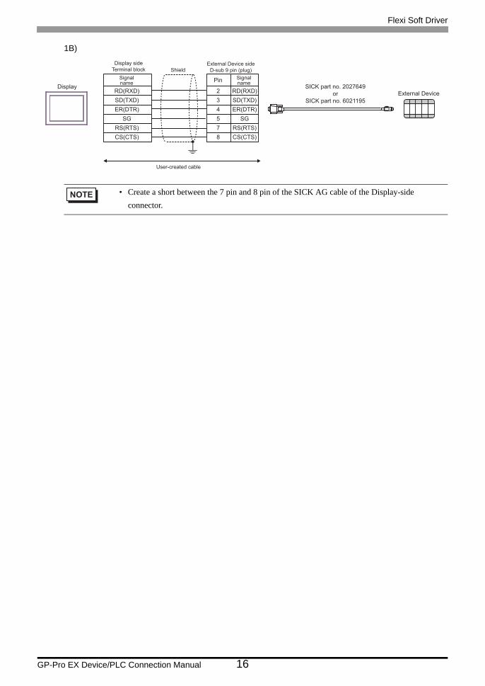
1B)
• Create a short between the 7 pin and 8 pin of the SICK AG cable of the Display-side connector.
SICK part no. 2027649or
SICK part no. 6021195
DisplayExternal Device
Display sideTerminal block
Signalname
RD(RXD)SD(TXD)ER(DTR)
SGRS(RTS)CS(CTS)
External Device sideD-sub 9 pin (plug)
Pin
234578
RD(RXD)SD(TXD)ER(DTR)
SGRS(RTS)CS(CTS)
ShieldSignalname
User-created cable
Flexi Soft Driver
GP-Pro EX Device/PLC Connection Manual 17
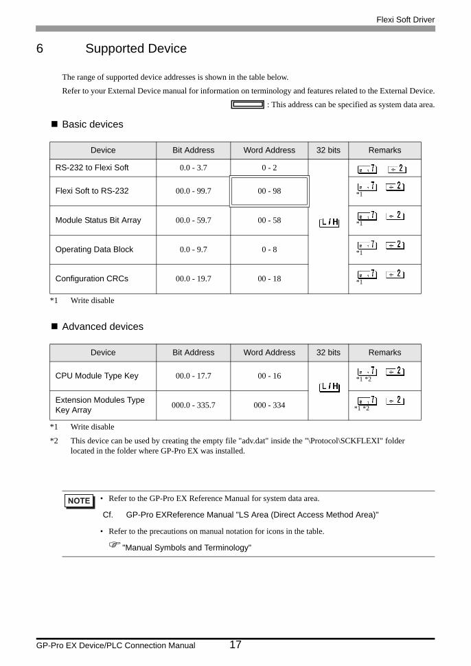
6 Supported Device
The range of supported device addresses is shown in the table below.
Refer to your External Device manual for information on terminology and features related to the External Device.
: This address can be specified as system data area.
Basic devices
Advanced devices
Device Bit Address Word Address 32 bits Remarks
RS-232 to Flexi Soft 0.0 - 3.7 0 - 2
Flexi Soft to RS-232 00.0 - 99.7 00 - 98
*1
*1 Write disable
Module Status Bit Array 00.0 - 59.7 00 - 58
*1
Operating Data Block 0.0 - 9.7 0 - 8
*1
Configuration CRCs 00.0 - 19.7 00 - 18
*1
Device Bit Address Word Address 32 bits Remarks
CPU Module Type Key 00.0 - 17.7 00 - 16
*1 *2
*1 Write disable
*2 This device can be used by creating the empty file "adv.dat" inside the "\Protocol\SCKFLEXI" folderlocated in the folder where GP-Pro EX was installed.
Extension Modules Type Key Array 000.0 - 335.7 000 - 334
*1 *2
• Refer to the GP-Pro EX Reference Manual for system data area.
Cf. GP-Pro EXReference Manual "LS Area (Direct Access Method Area)"
• Refer to the precautions on manual notation for icons in the table.
"Manual Symbols and Terminology"
Flexi Soft Driver
GP-Pro EX Device/PLC Connection Manual 18
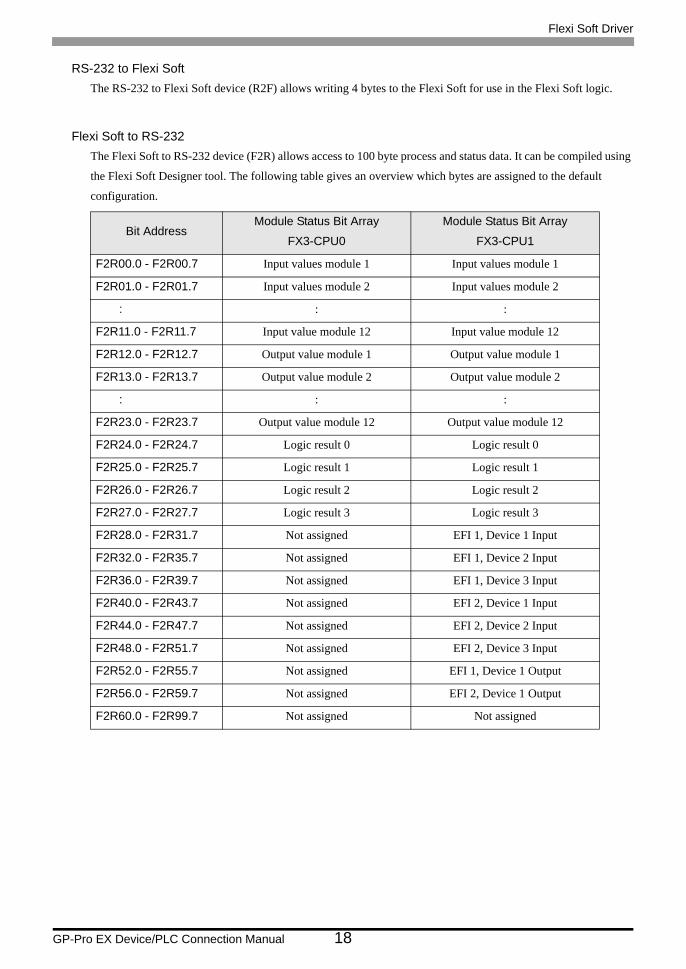
RS-232 to Flexi SoftThe RS-232 to Flexi Soft device (R2F) allows writing 4 bytes to the Flexi Soft for use in the Flexi Soft logic.
Flexi Soft to RS-232The Flexi Soft to RS-232 device (F2R) allows access to 100 byte process and status data. It can be compiled using
the Flexi Soft Designer tool. The following table gives an overview which bytes are assigned to the default
configuration.
Bit AddressModule Status Bit Array
FX3-CPU0
Module Status Bit Array
FX3-CPU1
F2R00.0 - F2R00.7 Input values module 1 Input values module 1
F2R01.0 - F2R01.7 Input values module 2 Input values module 2
: : :
F2R11.0 - F2R11.7 Input value module 12 Input value module 12
F2R12.0 - F2R12.7 Output value module 1 Output value module 1
F2R13.0 - F2R13.7 Output value module 2 Output value module 2
: : :
F2R23.0 - F2R23.7 Output value module 12 Output value module 12
F2R24.0 - F2R24.7 Logic result 0 Logic result 0
F2R25.0 - F2R25.7 Logic result 1 Logic result 1
F2R26.0 - F2R26.7 Logic result 2 Logic result 2
F2R27.0 - F2R27.7 Logic result 3 Logic result 3
F2R28.0 - F2R31.7 Not assigned EFI 1, Device 1 Input
F2R32.0 - F2R35.7 Not assigned EFI 1, Device 2 Input
F2R36.0 - F2R39.7 Not assigned EFI 1, Device 3 Input
F2R40.0 - F2R43.7 Not assigned EFI 2, Device 1 Input
F2R44.0 - F2R47.7 Not assigned EFI 2, Device 2 Input
F2R48.0 - F2R51.7 Not assigned EFI 2, Device 3 Input
F2R52.0 - F2R55.7 Not assigned EFI 1, Device 1 Output
F2R56.0 - F2R59.7 Not assigned EFI 2, Device 1 Output
F2R60.0 - F2R99.7 Not assigned Not assigned
Flexi Soft Driver
GP-Pro EX Device/PLC Connection Manual 19
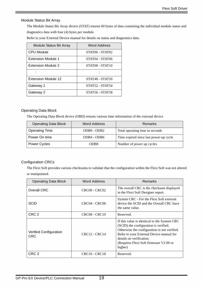
Module Status Bit ArrayThe Module Status Bit Array device (STAT) returns 60 bytes of data containing the individual module status and
diagnostics data with four (4) bytes per module.
Refer to your External Device manual for details on status and diagnostics data.
Operating Data BlockThe Operating Data Block device (OBD) returns various time information of the external device
Configuration CRCsThe Flexi Soft provides various checksums to validate that the configuration within the Flexi Soft was not altered
or manipulated.
Module Status Bit Array Word Address
CPU Module STAT00 - STAT02
Extension Module 1 STAT04 - STAT06
Extension Module 2 STAT08 - STAT10
: :
Extension Module 12 STAT48 - STAT50
Gateway 1 STAT52 - STAT54
Gateway 2 STAT56 - STAT58
Operating Data Block Word Address Remarks
Operating Time ODB0 - ODB2 Total operating time in seconds
Power On time ODB4 - ODB6 Time expired since last power-up cycle
Power Cycles ODB8 Number of power up cycles
Operating Data Block Word Address Remarks
Overall CRC CRC00 - CRC02 The overall CRC is the checksum displayed in the Flexi Soft Designer report.
SCID CRC04 - CRC06System CRC - For the Flexi Soft external device the SCID and the Overall CRC have the same value.
CRC 2 CRC08 - CRC10 Reserved.
Verified Configuration CRC CRC12 - CRC14
If this value is identical to the System CRC (SCID) the configuration is verified. Otherwise the configuration is not verified. Refer to your External Device manual for details on verification.(Requires Flexi Soft firmware V2.00 or higher)
CRC 3 CRC16 - CRC18 Reserved.
Flexi Soft Driver
GP-Pro EX Device/PLC Connection Manual 20
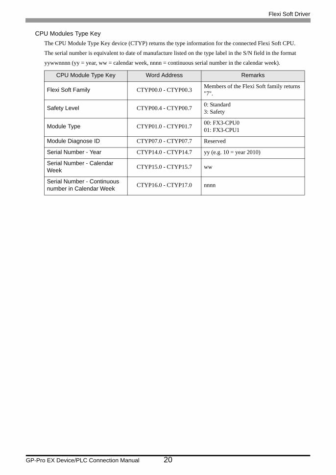
CPU Modules Type KeyThe CPU Module Type Key device (CTYP) returns the type information for the connected Flexi Soft CPU.
The serial number is equivalent to date of manufacture listed on the type label in the S/N field in the format
yywwnnnn (yy = year, ww = calendar week, nnnn = continuous serial number in the calendar week).
CPU Module Type Key Word Address Remarks
Flexi Soft Family CTYP00.0 - CTYP00.3 Members of the Flexi Soft family returns "7".
Safety Level CTYP00.4 - CTYP00.7 0: Standard3: Safety
Module Type CTYP01.0 - CTYP01.7 00: FX3-CPU001: FX3-CPU1
Module Diagnose ID CTYP07.0 - CTYP07.7 Reserved
Serial Number - Year CTYP14.0 - CTYP14.7 yy (e.g. 10 = year 2010)
Serial Number - Calendar Week CTYP15.0 - CTYP15.7 ww
Serial Number - Continuous number in Calendar Week CTYP16.0 - CTYP17.0 nnnn
Flexi Soft Driver
GP-Pro EX Device/PLC Connection Manual 21
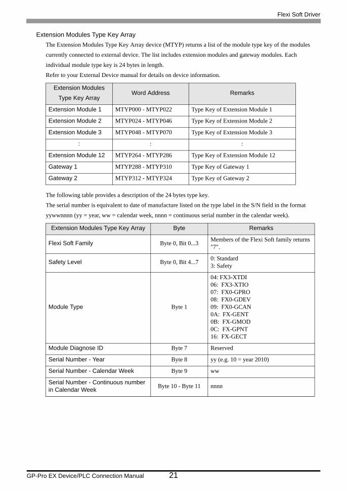
Extension Modules Type Key ArrayThe Extension Modules Type Key Array device (MTYP) returns a list of the module type key of the modules
currently connected to external device. The list includes extension modules and gateway modules. Each
individual module type key is 24 bytes in length.
Refer to your External Device manual for details on device information.
The following table provides a description of the 24 bytes type key.
The serial number is equivalent to date of manufacture listed on the type label in the S/N field in the format
yywwnnnn (yy = year, ww = calendar week, nnnn = continuous serial number in the calendar week).
Extension Modules
Type Key ArrayWord Address Remarks
Extension Module 1 MTYP000 - MTYP022 Type Key of Extension Module 1
Extension Module 2 MTYP024 - MTYP046 Type Key of Extension Module 2
Extension Module 3 MTYP048 - MTYP070 Type Key of Extension Module 3
: : :
Extension Module 12 MTYP264 - MTYP286 Type Key of Extension Module 12
Gateway 1 MTYP288 - MTYP310 Type Key of Gateway 1
Gateway 2 MTYP312 - MTYP324 Type Key of Gateway 2
Extension Modules Type Key Array Byte Remarks
Flexi Soft Family Byte 0, Bit 0...3 Members of the Flexi Soft family returns "7".
Safety Level Byte 0, Bit 4...7 0: Standard3: Safety
Module Type Byte 1
04: FX3-XTDI06: FX3-XTIO07: FX0-GPRO08: FX0-GDEV09: FX0-GCAN0A: FX-GENT0B: FX-GMOD0C: FX-GPNT16: FX-GECT
Module Diagnose ID Byte 7 Reserved
Serial Number - Year Byte 8 yy (e.g. 10 = year 2010)
Serial Number - Calendar Week Byte 9 ww
Serial Number - Continuous number in Calendar Week Byte 10 - Byte 11 nnnn
Flexi Soft Driver
GP-Pro EX Device/PLC Connection Manual 22
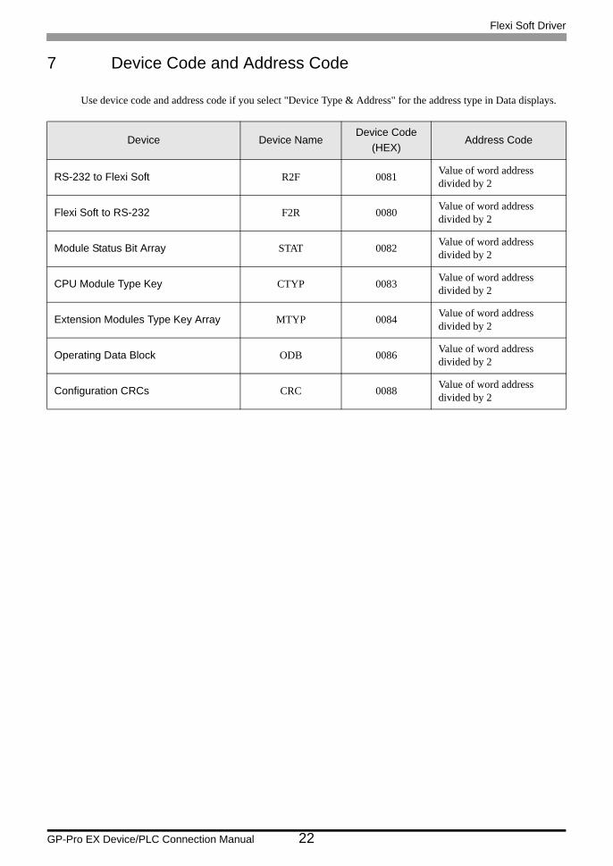
7 Device Code and Address Code
Use device code and address code if you select "Device Type & Address" for the address type in Data displays.
Device Device NameDevice Code
(HEX)Address Code
RS-232 to Flexi Soft R2F 0081 Value of word address divided by 2
Flexi Soft to RS-232 F2R 0080 Value of word address divided by 2
Module Status Bit Array STAT 0082 Value of word address divided by 2
CPU Module Type Key CTYP 0083 Value of word address divided by 2
Extension Modules Type Key Array MTYP 0084 Value of word address divided by 2
Operating Data Block ODB 0086 Value of word address divided by 2
Configuration CRCs CRC 0088 Value of word address divided by 2

Flexi Soft Driver
GP-Pro EX Device/PLC Connection Manual 23
8 Error Messages
Error messages are displayed on the Display screen as follows: "No.: Device Name: Error Message (Error
Occurrence Area)". Each description is shown below.
Display Examples of Error Messages
"RHAA035: PLC1: Error has been responded for device write command (Error Code: 1 [01H])"
Error Codes Specific to the External Device
Item Description
No. Error No.
Device Name Name of the External Device where an error has occurred. Device name is a title of the External Device set with GP-Pro EX. (Initial value [PLC1])
Error Message Displays messages related to an error that has occurred.
Error Occurrence Area
Displays the IP address or device address of the External Device where an error has occurred, or error codes received from the External Device.
• IP address is displayed as "IP address (Decimal): MAC address (Hex)".• Device address is displayed as "Address: Device address".• Received error codes are displayed as "Decimal [Hex]".
• Refer to your External Device manual for details on received error codes.• Refer to "Display-related errors" in "Maintenance/Troubleshooting Manual" for details on the
error messages common to the driver.
Error Code
(HEX)Error Description
08 RK512 handler is busy, RK512 request cannnot be processed.
0A Source/destination parameter invalid or timeout occured.
• The error codes shown above may display in cases when a Display and Flexi Soft Designer are connected concurrently or when multiple Displays are connected.
Flexi Soft Driver
GP-Pro EX Device/PLC Connection Manual 24
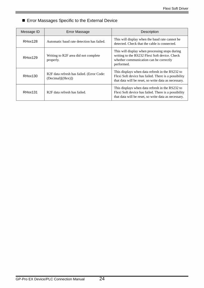
Error Massages Specific to the External Device
Message ID Error Massage Description
RHxx128 Automatic baud rate detection has failed. This will display when the baud rate cannot be detected. Check that the cable is connected.
RHxx129 Writing to R2F area did not complete properly.
This will display when processing stops during writing to the RS232 Flexi Soft device. Check whether communication can be correctly performed.
RHxx130 R2F data refresh has failed. (Error Code: (Decimal)[(Hex)])
This displays when data refresh in the RS232 to Flexi Soft device has failed. There is a possibility that data will be reset, so write data as necessary.
RHxx131 R2F data refresh has failed.This displays when data refresh in the RS232 to Flexi Soft device has failed. There is a possibility that data will be reset, so write data as necessary.