Flex+DriveII and MintDriveII Brushless AC Servo Controls · Jogging Absolute and relative...
13
C-25 AC Motors AC Controls Motion Controls Overview DC Motors DC Controls Software Linear Stages Linear Motors Engineering Information Feature MintDrive II Flex+Drive II FlexDrive II Drive Characteristics +/-10V command reference (programmable 0-10V) ✓ ✓ ✓ Pulse and Direction input ✓ ✓ ✓ Resolver ✓ ✓ ✓ Encoder ✓ ✓ ✓ Absolute Encoder (EnDat) ✓ ✓ ✓ Auto-tune (current, velocity and position) ✓ ✓ ✓ Position latch for high speed registration ✓ ✓ Programming Mint command line ✓ ✓ ✓ Mint program support ✓ ✓ Multi-tasking ✓ Programmable I/O ✓ ✓ ✓ Table driven PLC task for user defined operations ✓ ✓ ✓ Jog Window ✓ ✓ ✓ 16/256 Preset positions and speeds ✓ ✓ Program size 64K 16K Non-volatile user parameter storage ✓ Mint Interface Library (Windows API) Active X ✓ ✓ ✓ Move Types Jogging ✓ ✓ ✓ Absolute and relative positional moves ✓ ✓ Homing ✓ ✓ Gearing off master encoder with programmable gear ratio ✓ ✓ ✓ Cam profiling ✓ Flying shears ✓ Gearing with defined clutch distance ✓ Options CANopen master for peer to peer networking ✓ CANopen master for control of third party I/O devices ✓ CANopen slave ✓ ✓ ✓ DeviceNet Slave ✓ ✓ ✓ Profibus-DP Slave ✓ ✓ ✓ Flex+Drive II and MintDrive II Brushless AC Servo Controls The Flex+Drive II and MintDrive II Series of Brushless AC Servo Controls are a very flexible, versatile range to suit every application whether this is a simple analog command control, or a sophisticated single axis motion control. These controls have a common Windows ® front end, and connector/pin outs. Product Characteristics Overview
Transcript of Flex+DriveII and MintDriveII Brushless AC Servo Controls · Jogging Absolute and relative...

C-25
AC
Mo
tors
AC
Co
ntro
lsM
otio
nC
ont
rols
Ove
rvie
w
DC
Mo
tors
DC
Co
ntro
lsS
oft
war
eLi
near
Sta
ges
Line
arM
oto
rsE
ngin
eeri
ngIn
form
atio
n
Feature MintDriveII Flex+DriveII FlexDriveII
Drive Characteristics+/-10V command reference (programmable 0-10V) ✓ ✓ ✓
Pulse and Direction input ✓ ✓ ✓
Resolver ✓ ✓ ✓
Encoder ✓ ✓ ✓
Absolute Encoder (EnDat) ✓ ✓ ✓
Auto-tune (current, velocity and position) ✓ ✓ ✓
Position latch for high speed registration ✓ ✓
ProgrammingMint command line ✓ ✓ ✓
Mint program support ✓ ✓
Multi-tasking ✓
Programmable I/O ✓ ✓ ✓
Table driven PLC task for user defined operations ✓ ✓ ✓
Jog Window ✓ ✓ ✓
16/256 Preset positions and speeds ✓ ✓
Program size 64K 16KNon-volatile user parameter storage ✓
Mint Interface Library (Windows API) Active X ✓ ✓ ✓
Move TypesJogging ✓ ✓ ✓
Absolute and relative positional moves ✓ ✓
Homing ✓ ✓
Gearing off master encoder with programmable gear ratio ✓ ✓ ✓
Cam profiling ✓
Flying shears ✓
Gearing with defined clutch distance ✓
OptionsCANopen master for peer to peer networking ✓
CANopen master for control of third party I/O devices ✓
CANopen slave ✓ ✓ ✓
DeviceNet Slave ✓ ✓ ✓
Profibus-DP Slave ✓ ✓ ✓
Flex+DriveII and MintDriveII
Brushless AC ServoControls
The Flex+DriveII and MintDriveII Series of Brushless AC Servo Controls are a very flexible, versatile range to suitevery application whether this is a simple analog command control, or a sophisticated single axis motion control.These controls have a common Windows® front end, and connector/pin outs.
Product Characteristics Overview

C-26
AC
Mo
tors
AC
Co
ntrols
Mo
tion
Co
ntrols
Overview
D
C M
oto
rsD
C C
ontro
lsS
oftw
areLinearS
tages
LinearM
oto
rsE
ngineering
Inform
ation
The award-winning MintDriveII integrates a powerful motioncontroller and brushless AC servo control into a singlecompact package. Programmable in multi-tasking MintMT,multi-tasking provides control for motion, HMI and PLC tasks.Supports positional moves, cams, flying shears, andsoftware gearboxes.
The Flex+DriveII provides 16 preset positions or speeds. Anoption expands this to 256 preset positions. Contains 16Kmemory (programmable in MintMT) and will support single taskprogramming for indexing and gearing applications.
Fieldbus and I/O OptionsA number of industry standard fieldbusses are available as factoryfitted options for the Flex+DriveII and MintDriveII.
Option B: Dual CAN and I/O• On MintDriveII, provides two CAN channels
CAN1 – CANopen. See Option C for informationCAN2 - Baldor CAN – allows up to 63 Baldor I/O nodes to be added to the bus for expansion
• On Flex+DriveII, provides one CANopen channel. See Option C for information.
• Provided on both Flex+DriveII and MintDriveII digital I/O expansion via 25-pin D-type connector, with10 digital inputs – 12-24V PNP/NPN opto-isolated. 5 digital outputs – 12-24V PNP opto-isolated.
• The additional digital inputs expand the preset positions from 16 to 256.
Option C: CANopen• CANopen implementation according to CiA DS301 specification. • Master implementation – MintDriveII can be configuration as a
manager node giving access to DS401 I/O devices such as digital I/O and analog I/O.
• DS403 implementation for HMI for communicating with Baldor operator panels.
• Flex+DriveII can communicate with HMI panel or I/O devices if a manager is present on the bus (NextMovePCI, NextMove BXII
or MintDriveII)• Peer-to-peer communication, allowing data transfer between
Mint units, via the Comms Array.
• Mint provides full level functionality to monitor and control the stateof the bus. Full access can be given to the Object Dictionary of any remote device.
• Two RJ45 connectors for easy data chaining of units. • Optically isolated CAN drivers with internal 24V supply.
Option D: DeviceNet• Only slave implementation. • Conforms to ODVA DeviceNet Specification for the
Position Control, device type 10h. • Control of indexing moves for Flex+DriveII and MintDriveII. • Velocity and torque control over DeviceNet. • Access to Mint Comms Array allowing data transfer to Flex+DriveII
and MintDriveII. • Fault and position indicators, sent as an event. • Maximum of 63 nodes possible over the network. • Operating Baud rates of 125, 250 and 500kBits/sec.
Option P: Profibus-DP• DP Slave implementation• Default and custom process data definitions• Access to status information such as actual Velocity, Torque,
Position etc…• Set-point data such as demand Speed or Torque or target position• Access to local Drive I/O states• Data exchange with user MintMT programs• Up to 12Mbaud• Simple 2 wire multi-drop cabling system with Standard 9 Pin
D-Shell connection.

C-27
AC
Mo
tors
AC
Co
ntro
lsM
otio
nC
ont
rols
Ove
rvie
w
DC
Mo
tors
DC
Co
ntro
lsS
oft
war
eLi
near
Sta
ges
Line
arM
oto
rsE
ngin
eeri
ngIn
form
atio
n
MintDriveII Software FeaturesProgrammed in multi-tasking MintMT, MintDriveII is truly a flexible combined single axis motion controller anddrive. With its flexible I/O arrangement and move types, MintDriveII can easily take on the role of a machinecontroller, looking after the motion, PLC functionality and HMI tasks.
Positional Moves• Absolute and Relative• Trapezoidal • Speed Control
Master/follower• Electronic Gearbox and Clutch• Electronic Cam• Flying Shear
Flex+DriveII Software FeaturesThe Flex+DriveII is a versatile positioning drive supporting as standard 16 preset positions and jog speeds, withthe option of expanding this to 256 preset positions. Each of the first 16 presets can be programmed withindependent acceleration, deceleration and speed profile. Each move can be set for absolute or relativepositioning to a home point. The Flex+DriveII also supports as standard Mint programming for single task events.
Preset positions defined ina table. Can be exportedfor loading into anothercontrol.
Presetscalled fromthe Toolbox
Trigger move fromWorkBench ordigital inputs
SetupAll the controls are setup using the Windows front end, WorkBench which supports many features to get you upand running quickly.
Full program editor withcolor highlighting ofMintMT keywords.Dynamic syntaxchecking while you type.
Program Navigator -showing programstructure
Selectoptions forauto-tune
Output displays settings
• Motor selection database from motor catalog number or Baldor specification number.
• Autotuning of current, velocity and position loops. Options to measure motor resistance and inductance, motor inertia and detection of correct feedback alignment.
• PLC task for simple operations supporting AND and OR logic.
• Ability to record up to 32 error messages withtime stamp.
• SupportMe features to simplify customer support. One click and WorkBench will collect all the data about the control which can then be emailed for support.
Positional Moves• Absolute and Relative• Trapezoidal • Speed Control
Master/follower• Electronic Gearbox

C-28
AC
Mo
tors
AC
Co
ntrols
Mo
tion
Co
ntrols
Overview
D
C M
oto
rsD
C C
ontro
lsS
oftw
areLinearS
tages
LinearM
oto
rsE
ngineering
Inform
ation
MintDriveII
Single Axis Motion Controller.
Ideally suited to operateBrushless Motors – BSM Series,Linear Brushless – LMCF and LMBL Series
Input Voltage 115 VAC 1φW 230 VAC 1φW 230-460 VAC 3φW6
Bus Voltage 160VDC 300VDC 300-650 VDC
Output Amps 1 Catalog Catalog Pkg. Pkg. Catalog Pkg. Pkg.
Cont. Peak No.9 No.9 Size Size5 No.9 Size Size5
With internal logic power supply
2.5 5 MDH1A02TB-RN20 MDH2A02TB-RN20 A B – – –
5 10 MDH1A05TB-RN20 MDH2A05TB-RN20 C D – – –
7.5 15 MDH1A07TR-RN20 MDH2A07TR-RN20 D D – – –
Requires external +24V DC logic power supply
2.5 5 MDH1A02TB-RN23 MDH2A02TB-RN23 A B MDH4A02TB-RN23 G G
5 10 MDH1A05TB-RN23 MDH2A05TB-RN23 C D MDH4A05TB-RN23 G G
7.5 15 MDH1A07TR-RN23 MDH2A07TR-RN23 D D MDH4A07TR-RN23 G G
15 30 – – – – MDH4A15TR-RN23 H H
20 40 – – – – MDH4A20TR-RN23 H H
27.5 55 – – – – MDH4A27TR-RN23 H H
MintDriveII Catalog Numbers
Design Specifications
• 115 or 230 VAC direct on-line singlephase 2.5, 5, 7.5A continuous current
• Universal 230-460 VAC direct on-line 3phase 2.5 thru 27.5A continuouscurrent
• Resolver feedback with simulatedencoder output
• Optional encoder feedback withbuffered ppr output
• Position, velocity and torque modes• 2-14 bit analog inputs• 2-8 bit analog outputs• 8 digital inputs and 3 digital outputs for
machine control I/O• 5V and 24V pulse and direction
Features
• Powerful motion control functions
• Setup via Auto-Tuning• Common Microsoft Windows® front-
end with other Baldor motioncontrollers
• User Selectable RS232 and RS485serial communications
• Point-to-point moves• Software CAMs and gearing
Available Options
• Optional fieldbusses: CANopen,DeviceNet, Profibus-DP
• Resolver, encoder and absoluteencoder options
• Optional 10 additional digital inputs and5 outputs
• Optional External/Internal customersupplied 24 VDC logic supply
Protection Features
• Overvoltage protection • Short Circuit Proof• Over Temperature• Over Current protection• Undervoltage• Motor I2T protection• Electronic fusing• Loss of feedback protection• Drive Overload• Over Current Protection on
Digital Outputs
NOTE: Q RMS CurrentW 24V required for operation of I/Os (customer supplied).E 2.5 amp models have internal 20W 175 ohm (115/230 VAC) or 300W 200 ohm (400/460 VAC) regen resistor.
5 amp models have internal 40W 90 ohm (115/230 VAC) or 300W 200 ohm (400/460 VAC) regen resistor.R Logic supply code = 3. Customer must supply +24 VDC for logic supply.5 Package Size with Bus Option Card.6 Nominal input voltage range 230 - 460 VAC.7) Order encoder model for operation with linear motors.8) Order regen resistor for appropriate models, and motor and feedback cables separately.9 These units have 8/3 I/O and no CAN ports (BUS Options N = None)

C-29
AC
Mo
tors
AC
Co
ntro
lsM
otio
nC
ont
rols
Ove
rvie
w
DC
Mo
tors
DC
Co
ntro
lsS
oft
war
eLi
near
Sta
ges
Line
arM
oto
rsE
ngin
eeri
ngIn
form
atio
n
Typical ConnectionsThe MintDriveII is a single axis brushless AC servo control with integrated motion controller.

C-30
AC
Mo
tors
AC
Co
ntrols
Mo
tion
Co
ntrols
Overview
D
C M
oto
rsD
C C
ontro
lsS
oftw
areLinearS
tages
LinearM
oto
rsE
ngineering
Inform
ation
Description Unit SpecificationInput Voltage 1 phase models VAC 115, 1 phase (Range: 97-125)
230, 1 phase (Range: 220-250)3 phase models VAC 230-460, 3 phase (Range: 180-528)
Input Logic supply - VDC +20.4 to 28.8 Optional Customer Supplied Amps 1.75
Power on Surge 4A, 100ms @ 24 VDCOutput DC Bus Voltage VDC 160 (115 VAC 1φ input)
VDC 320 (230 VAC 1φ input)VDC 325 (230 VAC input) / 650 (460 VAC input)
Output Current 1 phase models Amps 2.5, 5.0, 7.5 3 phase models Amps 2.5, 5.0, 7.5, 15, 20, 27.5
Efficiency % >95Minimum Load Inductance µH 200Operating Altitude Feet 3300 (Above derate 1.1% per 1000)
Meters 1000 (Above derate 1.1% per 300)Operating Temperature °C 0 to +40 (Above derate 2.5%/°C to max 50°C)
°F 32 to 104 (Above derate 1%/°F to max 122°F)Storage Temperature °C -25 to +70
°F -13 to +158Humidify % 10 to 90 non-condensingShock G 1GVibration G 1G, 10-60 Hz
Technical Data
I/O Supply Customer Supplied. Note: 24V is necessary for operation of I/OOn-board Memory 512K Flash for firmware and program storage. 512K Flash. 8K NVRAM for parameter storageFeedback Resolver/Encoder/Absolute EncoderResolver 14 bit, ±3 count accuracySimulated Output 512/1024/2048/4096Encoder Accepts three channel encoders (A, B and Z) with Hall
Operates differential (TTL or RS 422) output type12MHz quadrature counts5V, 200mA power to encoder. 15-pin D-type
Digital Inputs 8 opto-isolated 24VCan be connected to positive or negative common (for use with NPN and PNP output transistors)Software configurable for forward and reverse limits, home, stop and drive errorSoftware programmable level and edge triggered2ms sample rate
Digital Outputs 3 opto-isolated 24V PNPSoftware configurable for Drive Okay. 50mA per channel, 350mA max source per channel, 500mA max for 3 channels
Fast Position Latch Inputs configurable to latch position of axis position and master encoder in 1µsRelay Output Fault output. Normally closed. 1A @ 30VDC or 0.5A @ 125VACAnalog Outputs 2 – 8 bit +/-10V. User ProgrammableAnalog Inputs/Command 2 – 14 bit resolution +/-10VReference Programmable gain and offsetMaster Encoder One channel for synchronization and following applications.
Incremental Encoder: RS422 differential AB signals with index (Z) pulse 2.5MHz maximum frequency
Pulse and Direction +5 and +24 VDC Pulse and Direction programmable from inputs 4 and 5 or master encoder inputmaximum input frequency of 1 MHz
Serial Ports User selectable via DIP switch for RS232 or RS485 communicationsRS232 – max Baud rate 57,600 for programmingRS485 – max Baud rate 19,200 for programming and multi-drop communications32 devices supported on RS485 port
Programming MintMT - Multi-tasking Motion Basic

C-31
AC
Mo
tors
AC
Co
ntro
lsM
otio
nC
ont
rols
Ove
rvie
w
DC
Mo
tors
DC
Co
ntro
lsS
oft
war
eLi
near
Sta
ges
Line
arM
oto
rsE
ngin
eeri
ngIn
form
atio
n
Dimensions (inches [millimeters])
Package Dimensions inches [mm] Weight
Size W H D W1 W2 W3 H1 H2 Lbs [Kgs]
A 2.66 [67.5] 6.81 [173] 6.00 [152] 1.57 [40] 0.59 [15] 1.57 [40] 7.70[195.5] 8.07 [205] 2.76 [1.25]
B 3.31 [84] 6.81 [173] 6.00 [152] 1.57 [40] 0.59 [15] 1.57 [40] 7.70[195.5] 8.07 [205] 3.42 [1.55]
C 3.64 [92.5] 6.81 [173] 6.00 [152] 1.57 [40] 0.91 [23] 1.57 [40] 7.70[195.5] 8.07 [205] 4.63 [2.1]
D 4.29 [109] 6.81 [173] 6.00 [152] 1.57 [40] 0.91 [23] 1.57 [40] 7.70[195.5] 8.07 [205] 5.07 [2.3]
G 2.56 [65] 14.06 [357] 10.31 [262] 1.81 [46] 1.28 [32.5] – 15.12 [384] 15.75 [400] 10.8 [4.9]
H 5.12 [130] 14.06 [357] 12.91 [328] 4.37 [111] 1.08 [27.5] 2.95 [75] 15.12 [384] 15.75 [400] 19.95 [9.05]
Dimensions (millimeters/inches)
Regen Resistors115 VAC Drive 230 VAC Drive 460/400 VAC Drive
Regen Resistor Regen Resistor Regen Resistor
Control Catalog Watts Control Catalog Watts Control Catalog Watts
MDH1A07TR- RG22 100 MDH2A07TR- RG39 100 MDH4A07TR- RG68 320
MDH4A15TR- RG27A 320
MDH4A20TR- RG27A 320
MDH4A27TR- RG11 640
Control Input Voltages CustomerContinuous Supplied
Current Rating 115 VAC 1φ 230 VAC 1φ 230-460 VAC 3φ 24 VDC2.5A FI0015A01 FI0014A00 FI0018A005.0A FI0015A00 FI0015A01 FI0018A007.5A FI0015A02 FI0015A0 FI0018A00 All models15A — — FI0018A01 FI0014A0020A — — FI0018A01
27.5A — — FI0018A01
Filters for CE
C-32
AC
Mo
tors
AC
Co
ntrols
Mo
tion
Co
ntrols
Overview
D
C M
oto
rsD
C C
ontro
lsS
oftw
areLinearS
tages
LinearM
oto
rsE
ngineering
Inform
ation
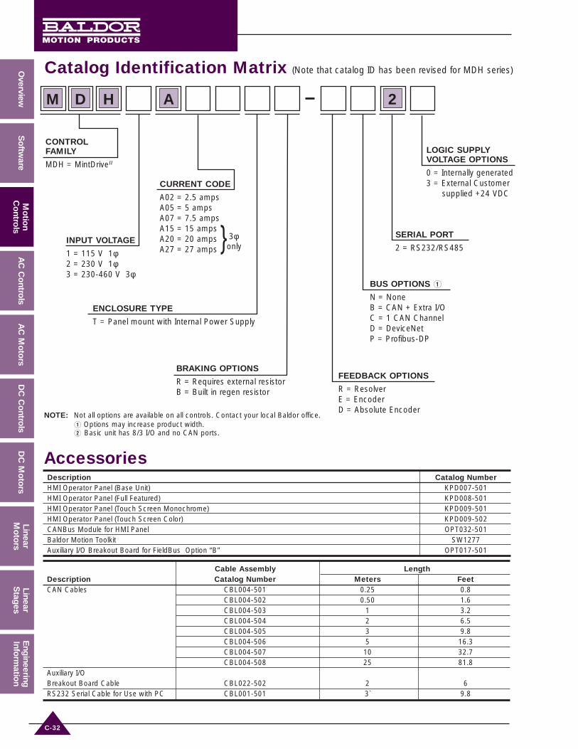
Catalog Identification Matrix (Note that catalog ID has been revised for MDH series)
CONTROLFAMILY
MDH = MintDriveII
INPUT VOLTAGE
1 = 115 V 1φ2 = 230 V 1φ3 = 230-460 V 3φ
FEEDBACK OPTIONS
R = ResolverE = EncoderD = Absolute Encoder
LOGIC SUPPLYVOLTAGE OPTIONS
0 = Internally generated3 = External Customer
supplied +24 VDCCURRENT CODE
A02 = 2.5 ampsA05 = 5 ampsA07 = 7.5 ampsA15 = 15 ampsA20 = 20 ampsA27 = 27 amps
ENCLOSURE TYPE
T = Panel mount with Internal Power Supply
BRAKING OPTIONS
R = Requires external resistorB = Built in regen resistor
BUS OPTIONS Q
N = NoneB = CAN + Extra I/OC = 1 CAN ChannelD = DeviceNetP = Profibus-DP
SERIAL PORT
2 = RS232/RS485
D H A
NOTE: Not all options are available on all controls. Contact your local Baldor office.Q Options may increase product width.W Basic unit has 8/3 I/O and no CAN ports.
M 2
3φ}only
Accessories
Cable Assembly LengthDescription Catalog Number Meters FeetCAN Cables CBL004-501 0.25 0.8
CBL004-502 0.50 1.6CBL004-503 1 3.2CBL004-504 2 6.5CBL004-505 3 9.8CBL004-506 5 16.3CBL004-507 10 32.7CBL004-508 25 81.8
Auxiliary I/O Breakout Board Cable CBL022-502 2 6RS232 Serial Cable for Use with PC CBL001-501 3` 9.8
Description Catalog NumberHMI Operator Panel (Base Unit) KPD007-501HMI Operator Panel (Full Featured) KPD008-501HMI Operator Panel (Touch Screen Monochrome) KPD009-501HMI Operator Panel (Touch Screen Color) KPD009-502CANBus Module for HMI Panel OPT032-501Baldor Motion Toolkit SW1277Auxiliary I/O Breakout Board for FieldBus Option “B” OPT017-501

C-33
AC
Mo
tors
AC
Co
ntro
lsM
otio
nC
ont
rols
Ove
rvie
w
DC
Mo
tors
DC
Co
ntro
lsS
oft
war
eLi
near
Sta
ges
Line
arM
oto
rsE
ngin
eeri
ngIn
form
atio
n
Flex+DriveII
The Flex+DriveII from Baldor integrates a powerful motioncontroller and brushless AC servo into a compact packagecapable of incremental positioning. Up to 16 pre-set point-to-point moves can be programmed into the drive, and ifyou need more, it can be expanded to 256. Moves may beincremental or absolute. Contains 16K memory(programmable in MintMT) and will support single taskprogramming for indexing and gearing applications.
Flex+DriveII Catalog Numbers
Design Specifications• Control Brushless or Linear Motors• Direct 115/230 1φ• Direct 230-400/460 3φ• Standard Resolver Feedback• Simulated Encoder Output• Setup via Software• 16 Pre-set Programmable Positions,
Expandable to 256• 16 K of Memory for Single Event
Programming• Common Microsoft Windows® Front
End, Shared with Motion Controllers
Available Options• CAN-Bus, DeviceNet, Profibus-DP• Encoder Feedback• Absolute Encoder Feedback• External Customer Supplied 24VDC
Logic Supply• 10 Additional Digital Inputs and 5
Additional Outputs
Velocity• Standard ± 10 VDC• Velocity/Current Mode of Operation• +5 VDC & +24 VDC Pulse and
Direction Input• Electronic Handwheel
(Pulse Follower) Input• Setup via Auto-Tuning
Special Features• Customer selectable RS232/RS485• 8 Digital Inputs• 3 Digital Outputs• 7 Segment Diagnostic Display• Auto-Tuning (Even Position!)• Position Latch for High Speed
Registration• Mint Program Support• Absolute and Relative Moves• Homing
Protection Features• Overvoltage • Short Circuit Proof• Over Temperature• Over Current• Resolver Fault• Under Voltage• Motor I2t• Electronic Fusing• Drive Overload• Loss of Feedback• Electronic Fusing• Over Current Protection
on Digital Outputs
AC Input Voltage 115 VAC 1φ W 230 VAC 1φ W 400/460 VAC 3φ W6
Bus Voltage 160 VDC 300 VDC 565/650 VDCOutput Amps Q Catalog Catalog Pkg. Pkg.5 Catalog R Pkg. Pkg.5
Cont. Peak Number Number Size Size Number Size Size
2.5 5 FPH1A02TB-RN20 E FPH2A02TB-RN20 E A B FPH4A02TB-RN23 E G G
5 10 FPH1A05TB-RN20 E FPH2A05TB-RN20 E C D FPH4A05TB-RN23 E G G
7.5 15 FPH1A07TR-RN20 FPH2A07TR-RN20 D D FPH4A07TR-RN23 G G
15 30 – – – – FPH4A15TR-RN23 H H
20 40 – – – – FPH4A20TR-RN23 H H
27.5 55 – – – – FPH4A27TR-RN23 H H
NOTE: Q RMS CurrentW 24V required for operation of I/Os (customer supplied).E 2.5 amp models have internal 20W 175 ohm (115/230 VAC) or 300W 200 ohm (400/460 VAC) regen resistor.
5 amp models have internal 40W 90 ohm (115/230 VAC) or 300W 200 ohm (400/460 VAC) regen resistor.R Logic supply code = 3. Customer must supply +24 VDC for logic supply.5 Package Size with Bus Option Card.6 Nominal input voltage range 230 - 460 VAC.7) Order encoder model for operation with linear motors.8) Order regen resistor for appropriate models, and motor and feedback cables separately.
Ideally suited to operateBrushless Motors – BSM Series,Linear Brushless – LMCF and LMBL Series

C-34
AC
Mo
tors
AC
Co
ntrols
Mo
tion
Co
ntrols
Overview
D
C M
oto
rsD
C C
ontro
lsS
oftw
areLinearS
tages
LinearM
oto
rsE
ngineering
Inform
ation
Typical ConnectionsThe Flex+DriveII is used for applications needing repeatable moves. It allows for up to 16 different positions to be“pre-set” in memory (expandable to 256). A specific “pre-set” position is selected through the “switch inputs” andthe “trigger” input activates the move. Repeatable moves become easy to accomplish, with this simple toprogram, stand alone package. Flex+DriveII can also be used for single axis applications requiring programmableposition moves.
MOTIONCONTROLLER

C-35
AC
Mo
tors
AC
Co
ntro
lsM
otio
nC
ont
rols
Ove
rvie
w
DC
Mo
tors
DC
Co
ntro
lsS
oft
war
eLi
near
Sta
ges
Line
arM
oto
rsE
ngin
eeri
ngIn
form
atio
n
Description Unit Specification
Input Voltage 1 phase modelsVAC 115, 1 phase (Range: 220-250)
230, 1 phase (Range: 180-528)Input Voltage 3 phase models VAC 230-460, 3 phase (Range: 184-253)
Input Logic supply - VDC +20.4 to 28.8 VDC
Optional Customer SuppliedAmps 1.75A
Power on Surge 4A, 100ms @ 24 VDC160 (115 VAC 1φ input)
Output DC Bus Voltage VDC 320 (230 VAC 1φ input)325 (230 VAC input) / 650 (460 VAC input)
Output CurrentAmps 2.5, 5.0, 7.5 (1φ input models)
2.5, 5.0, 7.5, 15, 20, 27.5Efficiency % >95Minimum Load Inductance µH 200
Operating AltitudeFeet 3300 (Above derate 1.1% per 1000)
Meters 1000 (Above derate 1.1% per 300)
Operating Temperature°C 0 to +40 (Above derate 2.5%/°C to max 50°C)°F 32 to 104 (Above derate 1%/°F to max 122°F)
Storage Temperature°C -25 to +70°F -13 to +158
Humidify % 10 to 90 non-condensingShock 1GVibration 1G, 10-60 Hz
Technical Data
External 24V Logic Supply Optional for single phase controls24VDC @1.75A. Power on surge of 4A for 100ms
I/O Supply Customer SuppliedNote: 24V is necessary for operation of I/O
On-board Memory 512K Flash for firmware and program storage 512K FlashFeedback Resolver/Encoder/Absolute EncoderResolver 14 bit, ±3 count accuracySimulated Output 512/1024/2048/4096Encoder Accepts three channel encoders (A, B and Z) with Hall
Operates differential (TTL or RS 422) output type12MHz quadrature counts5V, 200mA power to encoder15-pin D-type
Digital Inputs 8 opto-isolated 24VCan be connected to positive or negative common (for use with NPN and PNP output transistors)Software configurable for forward and reverse limits, home, stop and drive errorSoftware programmable level and edge triggered2ms sample rate
Digital Outputs 3 opto-isolated 24V PNPSoftware configurable for Drive Okay. 50mA per channel, 350mA max source per channel, 500mA max for 3 channels
Fast Position Latch Inputs configurable to latch position of axis position and master encoder in 1µsRelay Output Fault output
Normally closed. 1A @ 30VDC or 0.5A @ 125VACAnalog Inputs/Command 1 – 14 bit resolution +/-10VReference Programmable gain and offsetMaster Encoder One channel for synchronization and following applications.
Incremental Encoder: RS422 differential AB signals with index (Z) pulse 2.5MHz maximum frequency
Pulse and Direction Pulse and Direction programmable from inputs 4 and 5 or master encoder inputmaximum input frequency of 1 MHz
Serial Ports User selectable via DIP switch for RS232 or RS485 communicationsRS232 – max Baud rate 57,600 for programmingRS485 – max Baud rate 19,200 for programming and multi-drop communications32 devices supported on RS485 port

C-36
AC
Mo
tors
AC
Co
ntrols
Mo
tion
Co
ntrols
Overview
D
C M
oto
rsD
C C
ontro
lsS
oftw
areLinearS
tages
LinearM
oto
rsE
ngineering
Inform
ation
Dimensions (inches [millimeters])
Dimensions(inches [millimeters])
Package Dimensions inches [mm] Weight
Size W H D W1 W2 W3 H1 H2 Lbs [Kgs]
A 2.66 [67.5] 6.81 [173] 6.00 [152] 1.57 [40] 0.59 [15] 1.57 [40] 7.70[195.5] 8.07 [205] 2.76 [1.25]
B 3.31 [84] 6.81 [173] 6.00 [152] 1.57 [40] 0.59 [15] 1.57 [40] 7.70[195.5] 8.07 [205] 3.42 [1.55]
C 3.64 [92.5] 6.81 [173] 6.00 [152] 1.57 [40] 0.91 [23] 1.57 [40] 7.70[195.5] 8.07 [205] 4.63 [2.1]
D 4.29 [109] 6.81 [173] 6.00 [152] 1.57 [40] 0.91 [23] 1.57 [40] 7.70[195.5] 8.07 [205] 5.07 [2.3]
G 2.56 [65] 14.06 [357] 10.31 [262] 1.81 [46] 1.28 [32.5] – 15.12 [384] 15.75 [400] 10.8 [4.9]
H 5.12 [130] 14.06 [357] 12.91 [328] 4.37 [111] 1.08 [27.5] 2.95 [75] 15.12 [384] 15.75 [400] 19.95 [9.05]
Regen Resistors115 VAC Drive 230 VAC Drive 460/400 VAC Drive
Regen Resistor Regen Resistor Regen Resistor
Control Catalog Watts Control Catalog Watts Control Catalog Watts
FPH1A07TR- RG22 100 FPH2A07TR- RG39 100 FPH4A07TR- RG68 320
FPH4A15TR- RG27A 320
FPH4A20TR- RG27A 320
FPH4A27TR- RG11 640
Control Input Voltages CustomerContinuous Supplied
Current Rating 115 VAC 1φ 230 VAC 1φ 230-460 VAC 3φ 24 VDC2.5A FI0015A01 FI0014A00 FI0018A005.0A FI0015A00 FI0015A01 FI0018A007.5A FI0015A02 FI0015A0 FI0018A00 All models15A — — FI0018A01 FI0014A0020A — — FI0018A01
27.5A — — FI0018A01
Filters for CE

C-37
AC
Mo
tors
AC
Co
ntro
lsM
otio
nC
ont
rols
Ove
rvie
w
DC
Mo
tors
DC
Co
ntro
lsS
oft
war
eLi
near
Sta
ges
Line
arM
oto
rsE
ngin
eeri
ngIn
form
atio
n
Catalog Identification Matrix (Note that catalog ID has been revised for FPH series)
CONTROLFAMILY
FPH = Flex+DriveII
INPUT VOLTAGE
1 = 115 V 1φ2 = 230 V 1φ3 = 230-460 V 3φ
FEEDBACK OPTIONS
R = ResolverE = EncoderD = Absolute Encoder
LOGIC SUPPLYVOLTAGE OPTIONS
0 = Internally generated3 = External Customer
supplied +24 VDC
CURRENT CODE
A02 = 2.5 ampsA05 = 5 ampsA07 = 7.5 ampsA15 = 15 ampsA20 = 20 ampsA27 = 27 amps
ENCLOSURE TYPE
T = Panel mount with Internal Power Supply
BRAKING OPTIONS
R = Requires external resistorB = Built in regen resistor
BUS OPTIONS Q
N = NoneB = CAN + Extra I/OC = 1 CAN ChannelD = DeviceNetP = Profibus-DP
SERIAL PORT
2 = RS232/RS485
P H A
NOTE: Not all options are available on all controls. Contact your local Baldor office.Q Options may increase product width.
F 2
3φ}only