
Flex 5000 ATU 100 Service Manual - FlexRadio
25
Revision 1.0 1 Copyright FlexRadio Systems, 2010 FlexRadio Systems Automatic Antenna Tuning Unit ATU-100 for FLEX-5000 Product Manual Author: Graham Haddock, KE9H
Transcript of Flex 5000 ATU 100 Service Manual - FlexRadio

Revision 1.0 1 Copyright FlexRadio Systems, 2010
FlexRadio Systems
Automatic Antenna Tuning Unit
ATU-100 for FLEX-5000
Product Manual
Author: Graham Haddock, KE9H

Revision 1.0 2 Copyright FlexRadio Systems, 2010
Contents
Introduction …………………………………………...….. 3
Description ……………………………………………….. 4 Alignment and Test …………………………………….. 6 Automated Test …………………………………………. TBD Diagnostics ……………………………………………… 10 Appendix "A" Schematic. Appendix "B" Board Top View. Appendix “C” Installation Instructions

Revision 1.0 3 Copyright FlexRadio Systems, 2010
Introduction The ATU-100 is an automatic antenna tuner for installation and use in a FLEX-5000 Software Defined Radio. The product consists of a single PCB board designed for installation above the RF Power Amplifier (RFPA) in the FLEX-5000. It is connected to the radio by a ten conductor flat ribbon cable for control and power, and two coaxial cables, for input and output.
Fully Integrated 160-6M Automatic Tuning Unit (ATU)
Automatic Tuning Unit upgrade for FLEX-5000A and FLEX-5000C. The FLEX-5000-ATU-100 is an optional integrated state-of-the-art, processor-controlled switched-L tuning network for the FLEX-5000 that provides fully automatic antenna tuning across the entire HF range including 6 meters. It will tune dipoles, verticals, Yagis or virtually any coax fed antenna over a wide impedance range. Tuning functions are fully integrated into FlexRadio PowerSDR for ease of use and operation.

Revision 1.0 4 Copyright FlexRadio Systems, 2010
ATU Features and Specifications:
• Continuous coverage 1.8 to 54 MHz • Power rating HF (1.8 to 54 MHz): 5 to 100 Watts PEP (CW & SSB) • Will match a 10:1 SWR to 1.5:1 • Integrated with FlexRadio PowerSDR • Over 16000 memories for instantaneous band changing. • Tuning time: 0.5 to 6 seconds, full re-tune, <0.1 second memory tune • Tunes 6 to 1000 ohm loads (16 to 150Ω on 6M). • For Dipoles, Verticals, Vs, Beams or Coax Fed Antenna.
Detailed Description The Schematic is included in Appendix “A” The unit is powered by +12 Volts DC, supplied via the ribbon cable connector. Communication with the Flex-5000 radio is via an RS-232 bi-directional interface, which is also included in the ribbon cable. RF power in and output from the tuner is via the two labeled BNC connectors. There is a bypass function built into the tuner, which is also the default configuration, which directly connects the input to the output, bypassing all tuner functions. In the event of total failure, no initial commands, or no power applied to the board, the tuner will remain in this configuration. Up on receiving a command of “Select Antenna B,” relays K16 and K17 will become active, routing all signals through the tuning section of the circuit, instead of “bypass.” The tuning section of the ATU consists of seven sets of capacitors and seven inductors that can be selected in a binary progression, providing a tuning range of 0 to 1270 pF in 128 steps of 10 pF from the capacitance section, and a tuning range from 0 to 9.9 uH in 128 steps of approximately 0.1 uH in the inductance section. Through the action of relay K8, the two sections can be switched into two different “L” circuit configurations. The first has the capacitance section from input to ground and the inductance in series with the antenna. The second configuration has the inductance section in series with the input, and the capacitance section in parallel with the antenna connection. The sensor that is used to determine the tuning action of the ATU is the directional coupler created by T1 and the related components. This directional power sensor provides a DC output proportional to the power flowing through the coupler. The output of this coupler is 3 Volts DC, corresponding to 100 Watts. A perfectly matched antenna driven with 100 Watts would result in a sensor output of 3.0 Volts on the Forward test point, and no reflected power, corresponding to 0.0 Volts on the Reverse test point.

Revision 1.0 5 Copyright FlexRadio Systems, 2010
To the extent that a Voltage is present on the sensor reverse output, indicating that an antenna is not properly tuned, the on board microprocessor will begin selecting different capacitor and inductance values, or the “L” circuit configuration in an attempt to provide a good tuning solution. The microprocessor also has an associated memory, that is used to remember any successful tuning settings for each frequency, such that in the future, if that frequency is used again, the ATU can be instantly set to that tuning, without having to run through the entire tuning search process. To limit and prevent computer noise interference with the Flex-5000, the ATU microcomputer is normally asleep, and not operating. It only becomes active when the FLEX-5000 is transmitting, indicated by the presence of a forward power indication. This is monitored by comparator IC1, which then wakes up the microprocessor. The RED LED indicates that the processor is awake and sees an adequate RF level. The microprocessor measures the frequency of operation via the chain of IC8, IC9, and IC10. If there is a stored tuning solution for that frequency, it will be directly set into the tuning relays as “Memory Tune.” If a prior tuning solution is not in memory, or if the reverse power indication is simultaneously above a value indicating a VSWR of 2 or greater, the microprocessor will begin the tuning sequence, which can result in a continuous selection and operation of many relays for a period of up to six seconds. Upon finding a satisfactory tuning solution, the microprocessor will store it, and stop tuning activity. Upon disappearance of the transmit signal, the microprocessor will return to “sleep.” The tuning relays, K1 through K15, and bypass relays K16 and K17 are driven by relay drivers IC3 and IC5. These are controlled from the microprocessor via a SPI (Serial Peripheral Interface) bus. RS-232 serial communications between the ATU microprocessor and the FLEX-5000 radio are handled by IC11 which is a level translator and negative voltage generator.
Revision 1.0 6 Copyright FlexRadio Systems, 2010
Alignment and Test of ATU-100 for FLEX-5000 General configuration Manual testing using external holding fixture, and dedicated FLEX-5000 radio with associated PC and PowerSDR for testing. Connect 50 Ohm dummy load, 100 Watts or greater rating to Antenna connector #1 Connect 25 Ohm dummy load to Antenna Connector #2 Connect 300 Ohm dummy load to Antenna Connector #3 Connection of ATU-100 to be programmed, calibrated and tested, as follows: Connect 10 lead ribbon cable from “ATU” connector on FLEX-5000 PA board to 10 lead connector P1 on ATU under test and alignment. Connect BNC cable from output connector on FLEX-5000 PA board to PA Input on ATU Connect BNC Cable from ANT connector on ATU to Connector J4 on the inside rear vertical panel of the FLEX-5000 Testing the ATU will require PowerSDR Version 1.18.6 or newer, along with drivers FLEX-Firewire_Driver_v3.5.0.7171 or newer, and the FLEX-5000 must have ATU revision B programmed into the EEPROM in the FLEX-5000. Programming of the Microprocessor Turn on the Flex-5000 Plug the Microlabs Field Programmer into the ten pin programming connector, labeled “ICSP,” just above the microprocessor IC. The LED on the front of the field programmer should be “GREEN.” Press the program button. The LED should turn “RED.” Do not disconnect or change any connection on the programmer or ATU until the LED returns to the “GREEN” color. It will typically take 30 to 45 seconds for the programming cycle and return to “GREEN” status. Once the programmer has returned to “GREEN,” the programmer may be disconnected. Programming is complete. Turn off the FLEX-5000.

Revision 1.0 7 Copyright FlexRadio Systems, 2010
Power On Test Turn on the FLEX-5000. Both the RED and GREEN LEDs on the ATU should blink once, GREEN first, then RED. Alignment Open and start PowerSDR. Tune radio to 20 Meters, 14.100 MHz Select Antenna #1. Select Tune, 10 Watts +/- 2 Watts. RED LED should be lighted. Refer to photograph on following page, and diagram below. With a DC voltmeter connected negative to ground, positive to “REV” test point, Adjust C1 to for minimum voltage. It should null to less than 10 milliVolts. Adjust Tune Power to Drive = Maximum. Power should be between 95 and 105 Watts. With a DC voltmeter connected negative to ground, positive to “FWD” testpoint, adjust R4 for 3.00 Volts +/- 0.05 Volts. Return Tune Power to a setting of 10, and turn-off “TUNE.” Set R5 to midrange, that is, the flat top edge horizontal, the small point, pointing straight down at test point “REV.”

Revision 1.0 8 Copyright FlexRadio Systems, 2010

Revision 1.0 9 Copyright FlexRadio Systems, 2010
Testing Verify that Antenna 1 is still selected. Select “Bypass Mode.” Press tune and verify operation, power into PowerMaster, un-key. Open “ATU” Menu, Select “Semi-Automatic” Press “FULL TUNE” ATU should successfully tune with SWR less than 1.5 Change to 15 Meters / 21.100 MHz Select Ant 2 Select ATU/ “Semi-Automatic” / Press “FULL TUNE” ATU should successfully tune with SWR less than 1.5 Select Ant 3 (Still on 15 Meters / 21.100 MHz) Select ATU/ “Semi-Automatic” / Press “FULL TUNE” ATU should successfully tune with SWR less than 1.5 Change to 40 Meters / 7.100 MHz Select ATU/ “Semi-Automatic” / Press “FULL TUNE” ATU should successfully tune with SWR less than 1.5 Select Antenna # 2 (Still on 40 Meters / 7.100 MHz) Select ATU/ “Semi-Automatic” / Press “FULL TUNE” ATU should successfully tune with SWR less than 1.5 Return to 20 Meters / 14.100 MHz Select Antenna #1 Select ATU/ “Semi-Automatic” / Press “Memory TUNE” Unit should only click once, and instantly “memory” tune To previous setting from initial 20 Meters Test, with SWR less than 1.5 Functional test is complete

Revision 1.0 10 Copyright FlexRadio Systems, 2010
Diagnostics Unit will not program. Check for proper 5 V power. Check for proper orientation of connectors. Check for cold solder joints on microprocessor leads. Defective Microprocessor? – Replace. Unit does not blink on power up. Check for proper 5 Volt power Check for proper programming, reprogram microprocessor. Check for 20 MHz oscillation at pin __ on microprocessor Directional coupler will not “null.” Check for proper winding of directional coupler transformer T1. Check for proper connection of directional coupler transformer T1. Unit hangs, or tunes for unusually long period, and does not successfully complete tuning during one or more tests. Check for proper installation of all toroids, check for continuity of solder joints on all toroids. Check for proper installation and values on tuning capacitors (silver mica capacitors.) Check for defective relay. Voltage Test Points

Revision 1.0 Copyright FlexRadio Systems, 2010
Appendix "A" Schematic

0.11
u0.
22u
0.39
u0.
59u
1.25
u2.
5u5.
0u
20p
20p
39p
39p
82p
82p
160p
160p
330p
330p
620p
620p
1300
p
1300
p
+12V
+12V
+12V
+12V
+12V
+12V
+12V
+12V
+12V
+12V
+12V
+12V
+12V
+12V
+12V
+12V
+12V
GNDA
GNDA
GNDA
GNDA
UA
78M
05
20 MHz
20p20p
GN
D
DIR
_XFM
R
1N57
11W
+5V
100p
3.24k
4.7k
4.7k
GN
D
SD
-731
00-F
LTS
D-7
3100
-FLT
74H
C39
3D74
HC
393D
74H
C39
3D74
HC
393D
74A
HC
1G04
DB
V
M05
X2S
HD
10k
10k
25LC
640LM
311
10n
10n
.1u
1.8k
1.8k
10k150
1k
10k
10k
10n
10n
10n
10n
10n
10n
10n
10n
10n
10n
10n
10n
10n
10n
10n
GN
D
GN
DG
ND
GN
DG
ND
GN
DG
ND
GN
D
10n
GN
D
GN
D
GN
D
GND
.1u
+5V
GND
GN
D
10n
GN
DGN
D
GN
DG
ND
GN
D
GND
+5V
+5V
GN
DG
ND
GN
DG
ND
.1u
.1u
.1u.1u
.1u
.1u
.1u
.1u
.1u
GN
D
.1u
+5V
+5V
+5V
GN
D
GND
+5V
GN
D
GND
GND
TPIC
6B59
5
TPIC
6B59
5
GN
D
GN
DG
ND
GN
D
GN
DG
ND
GN
D
+5V
+5V
.1u .1u
GND GND10n
10n
10n
10n
10n
10n
10n
10n
10n
10n
10n
10n
10n
10n
10n
10n
GN
D
GN
D
10n
10n
GND
GN
D
10n
10n
650W
650W
650W
650W
650W
650W
950W
950W
950W
GN
DG
ND
950W
GNDA
GN
D
100u
.1u
.1u
GN
DG
ND
GN
D
+12V
10n
10n
GN
DG
ND 2.
4k2.
4k
100
10n
.1u
GND
GN
D
GN
D
GND
GN
D
MA
X232
EC
WE
20p
PIC
16F8
76S
O
M05
X2S
HD
+5V G
ND
+5V
Cop
yrig
ht F
lexR
adio
Sys
tem
s 20
09
ATU
-200
-R A
UTO
MAT
IC A
NTE
NN
A TU
NER
GR
NR
ED
MC
LRV
DD
GN
DC
LKD
ATA
121
K1
3 54
10 89
121
K2
3 54
10 89
121
K3
3 54
10 89
121
K4
3 54
10 89
121
K5
3 54
10 89
121
K6
3 54
10 89
121
K7
3 54
10 89
121
K9
3 54
10 89
121
K10
3 54
10 89
121
K11
3 54
10 89
121
K12
3 54
10 89
121
K13
3 54
10 89
121
K14
3 54
10 89
121
K15
3 54
10 89
121
K8
3 54
10 89
121
K17
3 54
10 89
121 K
16
3 54
10 89
L1L2
L3L4
L5L6
L7
C16
C23
C17
C24
C18
C25
C19
C29
C22
C26
C20
C27
C21
C28
IN1
OU
T3
4GN
D
IC2
2
QG1
C52C51
12
3
4
5T1
D1
D2
C2
R2
R3
R6
J1J2
A1
CLR
2
QA
3
QB
4
QC
5
QD
6
IC9A
A13
CLR
12
QA
11
QB
10
QC
9
QD
8
IC9B
714 IC9P GNDVCC
A1
CLR
2
QA
3
QB
4
QC
5
QD
6
IC10
AA
13
CLR
12
QA
11
QB
10
QC
9
QD
8
IC10
B
714 IC10
P
GNDVCC
24
IC8
35 IC8P GNDVCC
108642
97531
P1
13
2R5
13
2
R4
CS
1
SO2
WP
3
VSS
4SI
5SC
K6
HO
LD7
VCC
8
IC7
327
81
5 6
4
IC1
C31
C32
C30
D6
D7
R11
R12
R7R10
R8
R9
R13
C34
C35
C36
C37
C38
C39
C40
C6
C7
C8
C9
C10
C11
C12
C13
C3
D4
D3
D8 D9
C76
C33
C78
C79
C80
C67
C46
C61
C64
C65
C63 C66
D0
4
D1
5
D2
6
D3
7
D4
14
D5
15
D6
16
D7
17
~G9
RC
K12
~SR
CLR
8
SRC
K13
SER
IN3
SER
OU
T18
192
20
1
10
11
IC3
D0
4
D1
5
D2
6
D3
7
D4
14
D5
15
D6
16
D7
17
~G9
RC
K12
~SR
CLR
8
SRC
K13
SER
IN3
SER
OU
T18
192
20
1
10
11
IC5
C47 C62
C53
C54
C55
C56
C57
C58
C59
C60
C68
C69
C70
C71
C72
C73
C74
C75
C49
C48
C14
C15
L8L9
L13
L16
L17
L15
L14
L12
L11
FWD
RE
V
+5V
+12VL1
0
C43
C44
C45
C4
C5 R14
R15
R1
C77
C41
D10
GN
D
TP1
TP2TP3
TP4GN
D10
GN
D6
GN
D7
GN
D8
C1+
1
C1-
3
C2+
4
C2-
5
T1IN
11
T2IN
10
R1O
UT
12
R2O
UT
9
V+2
V-6
T1O
UT
14
T2O
UT
7
R1I
N13
R2I
N8
IC11
16 15GNDVCC
IC11
P
C1
MC
LR#/
THV
1
RA0
/AN
02
RA1
/AN
13
RA2
/AN
24
RA3
/AN
35
RA4
/T0C
KI6
RA5
/AN
47
OSC
1/C
LKIN
9
OSC
2/C
LKO
UT
10
RC
0/T1
OS
O11
RC
1/T1
OS
I12
RC
2/C
CP
113
RC
3/S
CK
14
SD
I/RC
415
SD
O/R
C5
16R
C6
17R
C7
18
820
INT/
RB0
21R
B122
RB2
23PG
M/R
B324
RB4
25R
B526
PGC
/RB6
27PG
D/R
B728
19
IC4
VDD
VSS
108642
97531
P2
X2-1
X2-2
X2-3
X2-4
X2-5
X2-6
K1
K1
K2
K2
K3
K3
K4
K4
K5
K5
K6
K6
K7
K7
K8
K8
K9
K9
K10
K10
K11
K11
K12
K12
K13
K13
K14
K14
K15
K15
K16
K16
K16
RF-
IN
RF-IN
FWD
FWD
FWD
FRE
Q
FRE
Q
CS
CS
SO
SO
SC
K
SC
K
SI
SI
RTS
R
RTS
R
RTS
R
INT
INT
RF-
INT
RF-
INT
DAT
A1
DAT
A1
STR
1
STR
1
CLK
1
CLK
1
RE
V
RE
V
CTS
R
CTS
R
RXR
RXR
TXR
TXR
TX23
2
TX232
CTS
232
CTS232
RX2
32
RX232
RTS
232
RTS232
V+ G
ND
BAL BAL/STR
V-
VCC
GN
D
NC
NC
GN
DG
ND
VCC
GN
D
NC
NC
GN
DG
ND
HIG
H-L
OW
Z
BYP
AS
SB
YPA
SS
1N41
48
1N41
48
SE
RIA
L M
EM
OR
Y
1N41
48
1N41
48
DIV
/16
DIV
/16
DIV
/16
DIV
/8
DC
GR
OU
ND
BR
IDG
E
1 W
3/4
W3/
4 W
RF
GR
OU
ND
DIG
ITA
L G
RO
UN
D
ICS
P
1N41
48
ICS
P

Revision 1.0 Copyright FlexRadio Systems, 2010
Appendix "B" PC Board Component View

FLE
XR
AD
IO S
YS
TEM
S
ATU
100
PC
-005
0 R
EV
BA
SS
Y:
RE
V:
CO
PR. F
LEXR
ADIO
SYS
TEM
S 20
10
P1
GND6
GND7
GND8IC11
C1
IC4
P2
X2

Revision 1.0 Copyright FlexRadio Systems, 2010
Appendix "C" Installation Instructions

Reproduction of this document in any form is expressly forbidden unless explicitly authorized by FlexRadio Systems. ©2005-2010 FlexRadio Systems
SDR-1000, FLEX-5000, FLEX-3000, FLEX-1500, PowerSDR, FlexWire, PanaFall, PanaScope and MultiWatch are trademarks of FlexRadio Systems. All rights reserved.
FLEX-5000A Antenna Tuning Unit
(ATU) Installation Instructions
ATU Board Revision 52B and above
Version August 18, 2010

Reproduction of this document in any form is expressly forbidden unless explicitly authorized by FlexRadio Systems. ©2005-2010 FlexRadio Systems
SDR-1000, FLEX-5000, FLEX-3000, FLEX-1500, PowerSDR, FlexWire, PanaFall, PanaScope and MultiWatch are trademarks of FlexRadio Systems. All rights reserved.
Materials Required:
• One (1) FLEX-5000 ATU (Assembly 52, Rev. B or higher) • One (1) Metal RF shield • One (1) ATU Control ribbon cable with connectors • One (1) mini coax jumper with BNC connectors • Four (4) 1” (2.54 cm) threaded spacers with post • Four (4) 1/4” (6.35 mm) threaded spacers with post • Four (4) 1/4” Hex nuts • Eight (8) Flat washers • Eight (8) Internal tooth lock washers
Software Required:
• FLEX-5000 EEPROM Updater (See steps 20 through 22) • The proper assembly and revision number must be entered
into the radio EEPROM before the radio will control this ATU.
Before starting, remember to observe proper ESD (electrostatic discharge) procedures before attempting the installation of the FLEX-5000 ATU in order to prevent damage that may occur from static charges that can build up on your body or work surfaces. This is especially a concern during the winter months or in climates where the relative humidity can be very low. Step 1. Turn off the Power to the FLEX-5000A and remove the power connector. Step 2. You will need to remove the top of the radio in order to gain access to the area where the Power Amplifier (PA) and Antenna Tuning Unit (ATU) are located. To do so, first remove the two side panels. In addition to the instructions below, you may refer to the KB article, How to Remove and Install the FLEX-5000A Top and Side Panels as a supplementary resource for removing the covers of the FLEX-5000A. (http://kc.flex-radio.com/KnowledgebaseArticle50382.aspx) Step 3. The two (2) side panels are attached to the radio with spring clips, and are easily pried off. Locate the small access/clearance gaps along the edge of the vertical front and rear black bezel (positioned about 2.5” (6.35 cm) from the top and bottom of the bezel), and pry the side panels off with either your

Reproduction of this document in any form is expressly forbidden unless explicitly authorized by FlexRadio Systems. ©2005-2010 FlexRadio Systems
SDR-1000, FLEX-5000, FLEX-3000, FLEX-1500, PowerSDR, FlexWire, PanaFall, PanaScope and MultiWatch are trademarks of FlexRadio Systems. All rights reserved.
fingernail or by sliding a small flat blade screwdriver into the gap between the bezel and the side panels. Be careful not to scratch the side panels if using a screwdriver. Step 4. Once the side panels have been removed, remove the top panel by using a T-20 torque driver (try a 1/8” wide flat blade screwdriver if you do not have a torque driver) to remove the two (2) screws on the left and the two (2) on the right. Then lift the top panel straight up and away from the unit. Do not remove the FLEX-5000 bottom cover.
Step 5. Remove the four (4) nuts that are holding down the PA board, but leave the flat washers in place. Do not discard the hex nuts.
Step 6. Install one of the four (4) 1” (2.54 cm) spacers in place of the four nuts that were just removed. Take care not to over-tighten the spacers, so that you do not strip the threads. (See Figure 1)
Figure 1 - PA w/ 1" spacers installed.

Reproduction of this document in any form is expressly forbidden unless explicitly authorized by FlexRadio Systems. ©2005-2010 FlexRadio Systems
SDR-1000, FLEX-5000, FLEX-3000, FLEX-1500, PowerSDR, FlexWire, PanaFall, PanaScope and MultiWatch are trademarks of FlexRadio Systems. All rights reserved.
Step 7. Plug one end of the ATU control ribbon cable into the keyed connector marked “SV2” on the edge of the PA unit. The red strip of the cable is oriented towards the front of the FLEX-5000. You can see the ribbon cable plugged into SV2 on the left side of Figure 1 above, just behind the 1” (2.54 cm) spacer. Lay the cable over the side of the FLEX-5000 chassis as shown in Figure 1. Step 8. Locate the metal RF shield, and observing the orientation of the mounting holes, place the shield on top of the 1” (2.54 cm) spacers with the spacer threads protruding from the tops of the metal RF shield. (See Figure 2)
Figure 2 - Placement of RF shield on top of 1" spacers
Reproduction of this document in any form is expressly forbidden unless explicitly authorized by FlexRadio Systems. ©2005-2010 FlexRadio Systems
SDR-1000, FLEX-5000, FLEX-3000, FLEX-1500, PowerSDR, FlexWire, PanaFall, PanaScope and MultiWatch are trademarks of FlexRadio Systems. All rights reserved.
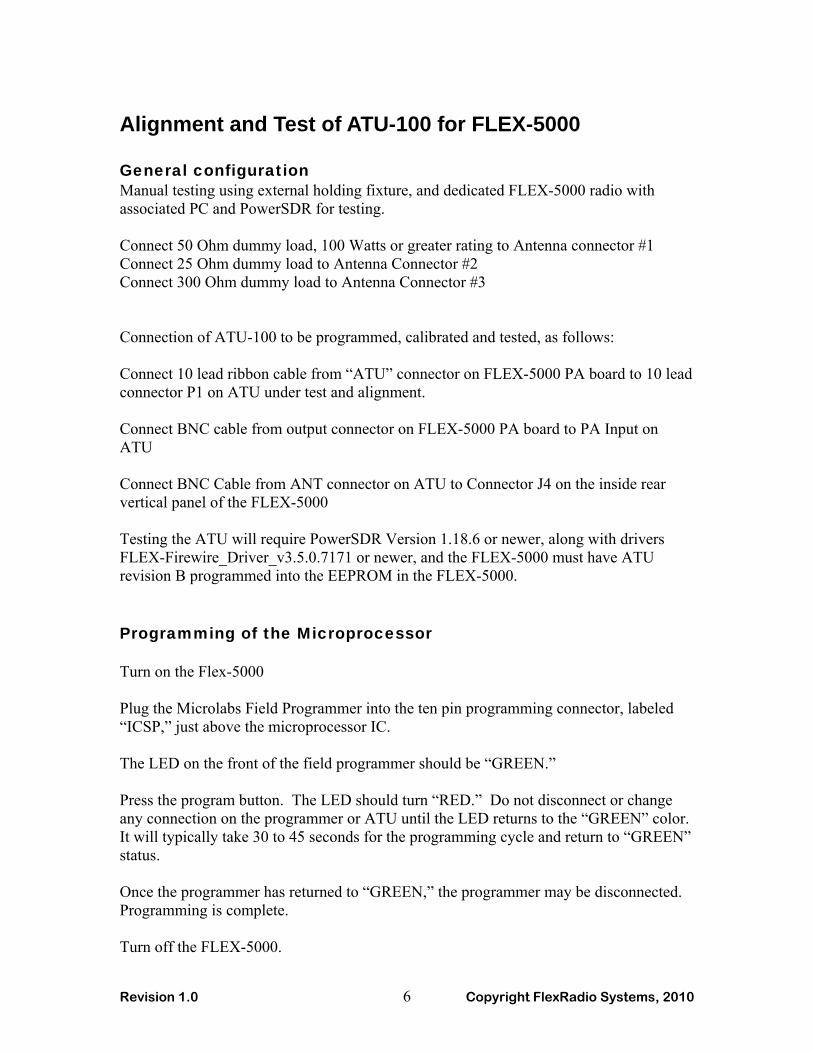
Step 9. Install one (1) flat washer and one (1) internal tooth lock washer over each of the four (4) screws protruding through the metal RF shield as shown in Figure 3.
Figure 3 - Flat washer and internal tooth lock washers on top
of RF shield
Step 10. Install one (1) 1/4” (6.35 mm) spacer over each of the four (4) screws protruding through the RF shield, but take care not to over tighten these soft aluminum spacers. (See Figure 4)
Reproduction of this document in any form is expressly forbidden unless explicitly authorized by FlexRadio Systems. ©2005-2010 FlexRadio Systems
SDR-1000, FLEX-5000, FLEX-3000, FLEX-1500, PowerSDR, FlexWire, PanaFall, PanaScope and MultiWatch are trademarks of FlexRadio Systems. All rights reserved.
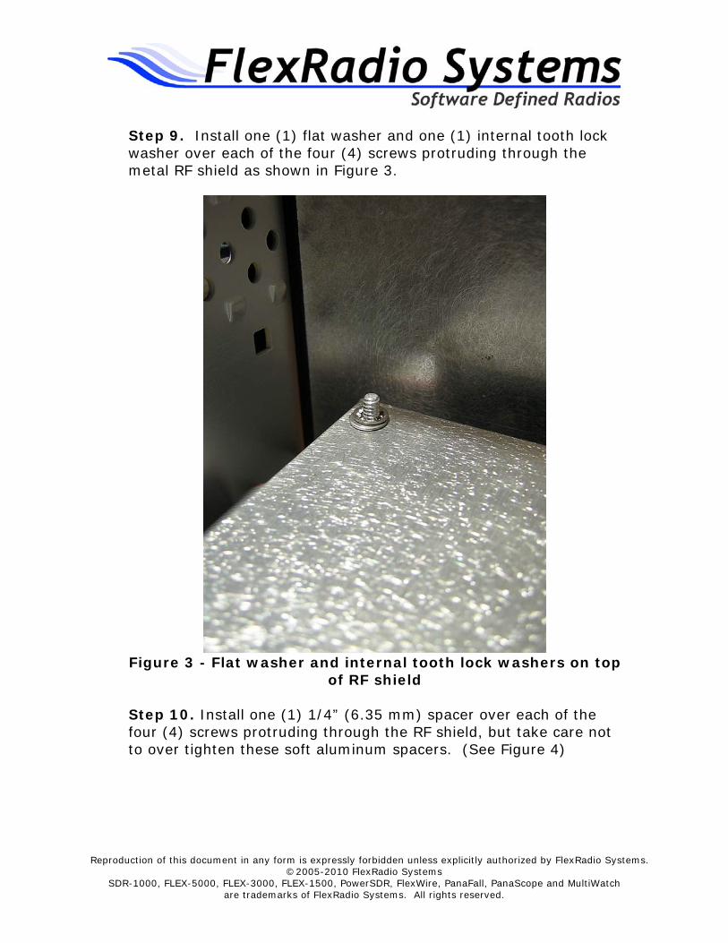
Figure 4 - Installation of four 1/4" spacers on top of shield
Step 11. Carefully position the ATU over the 1/4” (6.35 mm) spacers with the BNC connectors facing the rear of the FLEX-5000. (See Figure 5) Record the serial number on the ATU board. It has the format of xxx-xxxx. This will be needed later on in the installation procedure.
Reproduction of this document in any form is expressly forbidden unless explicitly authorized by FlexRadio Systems. ©2005-2010 FlexRadio Systems
SDR-1000, FLEX-5000, FLEX-3000, FLEX-1500, PowerSDR, FlexWire, PanaFall, PanaScope and MultiWatch are trademarks of FlexRadio Systems. All rights reserved.
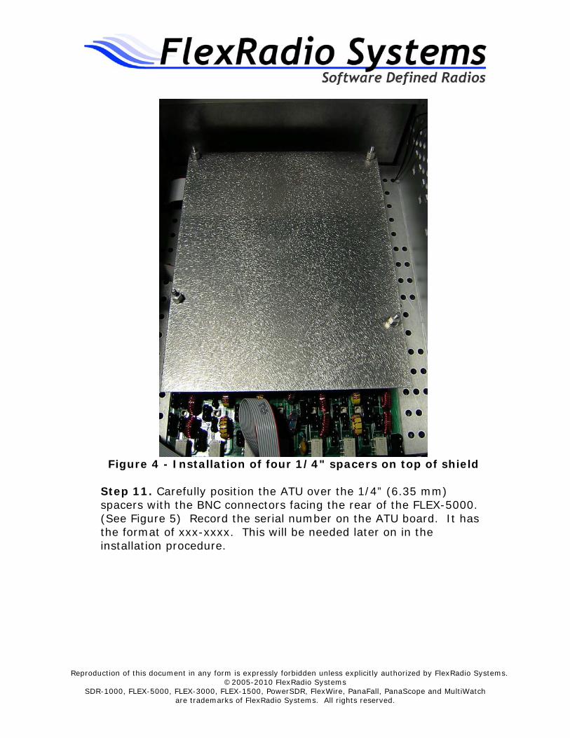
Figure 5 - Placement of ATU onto spacers above shield
Step 12. Install one (1) flat washer, one (1) internal tooth lock washer, and one (1) hex nut over each of the four (4) screws upon which the ATU is mounted. Hand tighten the nuts, but be careful not to strip the threads. (See Figure 6)

Reproduction of this document in any form is expressly forbidden unless explicitly authorized by FlexRadio Systems. ©2005-2010 FlexRadio Systems
SDR-1000, FLEX-5000, FLEX-3000, FLEX-1500, PowerSDR, FlexWire, PanaFall, PanaScope and MultiWatch are trademarks of FlexRadio Systems. All rights reserved.
Figure 6 - Flat washer, internal tooth lock washer, and hex
nut securing the ATU
Step 13. Connect the other end of the ATU control ribbon cable to connector labeled “P1” on the side of the ATU board located towards the front of the FLEX-5000. The red strip (pin 1) on the cable is oriented towards the front of the FLEX-5000. Do NOT connect the ATU control cable to the ICSP connector in the middle of the ATU board. (See Figure 5) Step 14. Locate the short mini coax cable connection between the BNC connector labeled “PA Out” on the PA board and the BNC connector labeled “J4 PA/ATU” on the RFIO board mounted on the rear panel of the radio.
Step 15. Remove the mini coax cable from the RFIO BNC connector referenced in step 14 and connect it to the BNC connector on the ATU board labeled “PA J1”. (See Figure 7)
Reproduction of this document in any form is expressly forbidden unless explicitly authorized by FlexRadio Systems. ©2005-2010 FlexRadio Systems
SDR-1000, FLEX-5000, FLEX-3000, FLEX-1500, PowerSDR, FlexWire, PanaFall, PanaScope and MultiWatch are trademarks of FlexRadio Systems. All rights reserved.
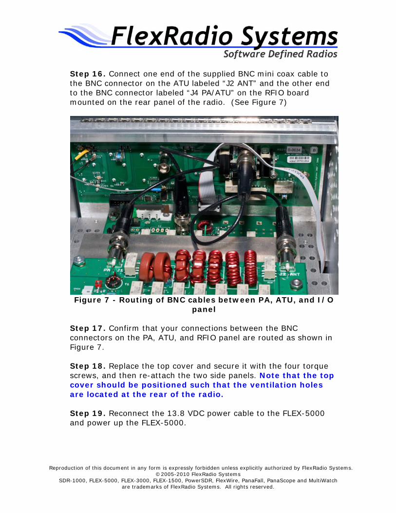
Step 16. Connect one end of the supplied BNC mini coax cable to the BNC connector on the ATU labeled “J2 ANT” and the other end to the BNC connector labeled “J4 PA/ATU” on the RFIO board mounted on the rear panel of the radio. (See Figure 7)
Figure 7 - Routing of BNC cables between PA, ATU, and I/O
panel
Step 17. Confirm that your connections between the BNC connectors on the PA, ATU, and RFIO panel are routed as shown in Figure 7. Step 18. Replace the top cover and secure it with the four torque screws, and then re-attach the two side panels. Note that the top cover should be positioned such that the ventilation holes are located at the rear of the radio. Step 19. Reconnect the 13.8 VDC power cable to the FLEX-5000 and power up the FLEX-5000.

Reproduction of this document in any form is expressly forbidden unless explicitly authorized by FlexRadio Systems. ©2005-2010 FlexRadio Systems
SDR-1000, FLEX-5000, FLEX-3000, FLEX-1500, PowerSDR, FlexWire, PanaFall, PanaScope and MultiWatch are trademarks of FlexRadio Systems. All rights reserved.
Step 20. Download the FLEX-5000 EEPROM Updater for the ATU from the FlexRadio Systems web site. Refer to the KB article, FLEX-5000 ATU EEPROM Updater (Assy:52) for the location of the EEPROM updater software program (http://kc.flex-radio.com/KnowledgebaseArticle50474.aspx). Step 21. Run the EEPROM Updater program. Step 22. Start PowerSDR and open the Setup form. Verify that the ATU is displayed on the General->Hardware Config tab and shows the proper serial number and revision 52B in parentheses. If not displayed, then enter the Assembly Revision 52B into the revision window. The radio will not control this series ATU without this assembly and revision number properly entered into the EEPROM. Step 23. Refer to the FLEX-5000 User’s Manual for instructions on the operation of the ATU using PowerSDR.


![[ATU] - Fases Do Capitalismo](https://static.fdocuments.in/doc/165x107/577c86b51a28abe054c25465/atu-fases-do-capitalismo.jpg)


