FLEX 5-1470 1570 HMM · Lenovo ideapad FLEX 5-1470/Lenovo ideapad FLEX 5-1570 Hardware Maintenance...
82
Lenovo ideapad FLEX 5-1470 Lenovo ideapad FLEX 5-1570 Hardware Maintenance Manual
Transcript of FLEX 5-1470 1570 HMM · Lenovo ideapad FLEX 5-1470/Lenovo ideapad FLEX 5-1570 Hardware Maintenance...
Lenovo ideapadFLEX 5-1470 Lenovo ideapadFLEX 5-1570Hardware Maintenance Manual
Notes:• Beforeusingthisinformationandtheproductitsupports,besuretoreadthegeneralinformationunder“Notices”onpage77.
• Thismanualappliestothefollowingmodels:LenovoideapadFLEX5-1470/LenovoideapadFLEX5-1570.TheillustrationsusedinthismanualareforLenovoideapadFLEX5-1470unlessotherwisestated.
First Edition (March 2017)© Copyright Lenovo 2017. All rights reserved.LIMITED AND RESTRICTED RIGHTS NOTICE: If data or software is delivered pursuant a General Services Administration “GSA” contract, use, reproduction, or disclosure is subject to restrictions set forth in Contract No. GS-35F-05925.© 2017 Lenovo
iii
ContentsAbout this manual ....................................... iv
Safety information ........................................ 1General safety ................................................ 2Electrical safety .............................................. 3Safety inspection guide .................................. 5Handling devices that are sensitive to electrostatic discharge .................................... 6Grounding requirements ................................. 6Safety notices: multilingual translations.......... 7Laser compliance statement......................... 14
Important service information ................... 16Strategy for replacing FRUs ......................... 16
Strategy for replacing a hard disk drive ............17Important notice for replacing a system board ................................................................17
Important information about replacing RoHS compliant FRUs ................................. 18
General checkout ...................................... 19What to do first ............................................. 20Power system checkout................................ 21
Checking the AC adapter .................................21Checking operational charging .........................22Checking the battery pack ................................22
Related service information ...................... 23Restoring the factory contents by using OneKey Recovery ........................................ 23
Restore of factory default .................................23Passwords .................................................... 24
Power-on password ..........................................24Hard-disk password ..........................................24Supervisor password ........................................24
Power management ..................................... 25Putting the computer to sleep or shutting it down ..............................................................25Putting your computer to sleep .........................25Shutting down the computer .............................25
Lenovo ideapad FLEX 5-1470/Lenovo ideapad FLEX 5-1570.................................. 26Specifications ............................................... 26Status indicators ........................................... 27Keyboard function keys ................................ 28FRU replacement notices ............................. 29
Screw notices ..................................................29Removing and replacing an FRU ................. 30
1010 Base cover ...............................................311020 Battery pack .............................................331030 Solid state disk ........................................34
1040 Hard disk drive .........................................351050 PCI Express Mini Card for wireless LAN ...................................................................361060 Speakers .................................................381070 DIMM .......................................................391080 Fan and Heat Sink assembly ...................411090 IO board ...................................................441100 System board ...........................................461110 Upper case ..............................................481120 DC-in cable ..............................................501130 LCD unit ...................................................511140 Camera board, sensor board and EDP cable .........................................................541150 LCD hinges ..............................................581160 Fingerprint module (on select models) ......60
Locations ...................................................... 62Front and right-side view ..................................62Bottom and left-side view ................................63Rear view .........................................................64
Parts list ........................................................ 65Overall ..............................................................66LCD FRUs ........................................................71Miscellaneous parts ..........................................72AC adapters ......................................................73Screws ..............................................................73Power cords ......................................................74
Notices......................................................... 77Trademarks .................................................. 78
iv
About this manual
This manual contains service and reference information for the following Lenovo products:
Lenovo ideapad FLEX 5-1470/Lenovo ideapad FLEX 5-1570Use this manual to troubleshoot problems.The manual is divided into the following sections:• The common sections provide general information, guidelines, and safety
information required for servicing computers.• The product-specific section includes service, reference, and product-specific
parts information.
Important:ThismanualisintendedonlyfortrainedservicerswhoarefamiliarwithLenovoproducts.Usethismanualtotroubleshootproblemseffectively.BeforeservicingaLenovoproduct,makesure toreadall the informationunder“Safetyinformation”onpage1and“Importantserviceinformation”onpage16.
1
Safety information
Safety information
This chapter presents the following safety information that you need to get familiar with before you service a Lenovo ideapad FLEX 5-1470/Lenovo ideapad FLEX 5-1570 computer:• “General safety” on page 2• “Electrical safety” on page 3• “Safety inspection guide” on page 5• “Handling devices that are sensitive to electrostatic discharge” on page 6• “Grounding requirements” on page 6• “Safety notices: multilingual translations” on page 7• “Laser compliance statement” on page 14
2
Lenovo ideapad FLEX 5-1470/Lenovo ideapad FLEX 5-1570 Hardware Maintenance Manual
General safetyFollow these rules below to ensure general safety:• Observe a good housekeeping in the area where the machines are put
during and after the maintenance.• When lifting any heavy object:
1. Make sure that you can stand safely without slipping.2. Distribute the weight of the object equally between your feet.3. Use a slow lifting force. Never move suddenly or twist when you attempt
to lift it.4. Lift it by standing or pushing up with your leg muscles; this action could
avoid the strain from the muscles in your back. Do not attempt to lift any object that weighs more than 16 kg (35 lb) or that you think is too heavy for you.
• Do not perform any action that causes hazards to the customer, or that makes the machine unsafe.
• Before you start the machine, make sure that other service representatives and the customer are not in a hazardous position.
• Please remove covers and other parts in a safe place, away from all personnel, while you are servicing the machine.
• Keep your toolcase away from walk areas so that other people will not trip over it.
• Do not wear loose clothing that can be trapped in the moving parts of the machine. Make sure that your sleeves are fastened or rolled up above your elbows. If your hair is long, fasten it.
• Insert the ends of your necktie or scarf inside clothing or fasten it with the nonconductive clip, about 8 centimeters (3 inches) from the end.
• Do not wear jewelry, chains, metal-frame eyeglasses, or metal fasteners for your clothing.Attention: Metal objects are good electrical conductors.
• Wear safety glasses when you are hammering, drilling, soldering, cutting wire, attaching springs, using solvents, or working in any other conditions that may be hazardous to your eyes.
• After service, reinstall all safety shields, guards, labels, and ground wires. Replace any safety device that is worn or defective.
• Reinstall all covers correctly before returning the machine to the customer.• Fan louvers on the machine help to prevent the overheating of internal
components. Do not obstruct fan louvers or cover them with labels or stickers.

3
Safety information
Electrical safetyObserve the following rules when working on electrical equipments.
Important:Useonlyapproved toolsand testequipments.Somehand toolshavehandlescoveredwithasoftmaterial thatdoesnot insulateyouwhenworkingwithliveelectricalcurrents.Manycustomershaverubberfloormatsnear theirmachines thatcontainsmallconductivefiberstodecreaseelectrostaticdischarges.Donotusesuchkindofmattoprotectyourselffromelectricalshock.
• Find the room emergency power-off (EPO) switch, disconnecting switch or electrical outlet. If an electrical accident occurs, you can then operate the switch or unplug the power cord quickly.
• Do not work alone under hazardous conditions or near the equipment that has hazardous voltages.
• Disconnect all power before:– Performing a mechanical inspection– Working near power supplies– Removing or installing main units
• Before you start to work on the machine, unplug the power cord. If you cannot unplug it, ask the customer to power-off the wall box that supplies power to the machine, and to lock the wall box in the off position.
• If you need to work on a machine that has exposed electrical circuits, observe the following precautions:– Ensure that another person, familiar with the power-off controls, is near
you. Attention: Another person must be there to switch off the power, if
necessary. – Use only one hand when working with powered-on electrical equipment;
keep the other hand in your pocket or behind your back. Attention: An electrical shock can occur only when there is a complete
circuit. By observing the above rule, you may prevent a current from passing through your body.
– When using testers, set the controls correctly and use the approved probe leads and accessories for that tester.
– Stand on suitable rubber mats (obtained locally, if necessary) to insulate you from grounds such as metal floor strips and machine frames.
Observe the special safety precautions when you work with very high voltages; instructions for these precautions are in the safety sections of maintenance information. Be extremely careful when you measure the high voltages.• Regularly inspect and maintain your electrical hand tools for safe operational
condition. • Do not use worn or broken tools and testers.• Never assume that power has been disconnected from a circuit. First, check
it to make sure that it has been powered off.
4
Lenovo ideapad FLEX 5-1470/Lenovo ideapad FLEX 5-1570 Hardware Maintenance Manual
• Always look carefully for possible hazards in your work area. Examples of these hazards are moist floors, nongrounded power extension cables, power surges, and missing safety grounds.
• Do not touch live electrical circuits with the reflective surface of a plastic dental mirror. The surface is conductive; such touching can cause personal injury and machine damage.
• Do not service the following parts with the power on when they are removed from their normal operating places in a machine: – Power supply units– Pumps– Blowers and fans– Motor generatorsand similar units. (This practice ensures correct grounding of the units.)
• If an electrical accident occurs:– Caution: do not become a victim yourself.– Switch off the power.– Send the victim to get medical aid.
5
Safety information
Safety inspection guideThe purpose of this inspection guide is to assist you in identifying potential unsafe conditions. As each machine was designed and built, required safety items were installed to protect users and service personnel from injury. This guide addresses only those items. You should use good judgment to identify potential safety hazards according to the attachment of non-Lenovo features or options not covered by this inspection guide.
If any unsafe conditions are present, you must determine how serious the apparent hazard could be and whether you can continue without first correcting the problem.
Consider these conditions and the safety hazards they present: • Electrical hazards, especially primary power (primary voltage on the frame
can cause serious or fatal electrical shock) • Explosive hazards, such as a damaged CRT face or a bulging capacitor• Mechanical hazards, such as loose or missing hardware
To determine whether there are any potential unsafe conditions, use the following checklist at the beginning of every service task. Begin the checks with the power off, and the power cord disconnected.
Checklist:1. Check exterior covers for damage (loose, broken, or sharp edges).2. Turn off the computer. Disconnect the power cord.3. Check the power cord for:
a. A third-wire ground connector in good condition. Use a meter to measure third-wire ground continuity for 0.1 ohm or less between the external ground pin and the frame ground.
b. The power cord should be the type specified in the parts list.c. Insulation must not be frayed or worn.
4. Check for cracked or bulging batteries.5. Remove the cover.6. Check for any obvious non-Lenovo alterations. Use good judgment as to the
safety of any non-Lenovo alterations.7. Check inside the unit for any obvious unsafe conditions, such as metal
filings, contamination, water or other liquids, or signs of fire or smoke damage.
8. Check for worn, frayed, or pinched cables.9. Check that the power-supply cover fasteners (screws or rivets) have not
been removed or tampered with.
6
Lenovo ideapad FLEX 5-1470/Lenovo ideapad FLEX 5-1570 Hardware Maintenance Manual
Handling devices that are sensitive to electrostatic dischargeAny computer part containing transistors or integrated circuits (ICs) should be considered sensitive to electrostatic discharge (ESD). ESD damage can occur when there is a difference in charge between objects. Protect against ESD damage by equalizing the charge so that the machine, the part, the work mat, and the person handling the part are all at the same charge.
Notes:1. Useproduct-specificESDprocedureswhen theyexceed the requirements
notedhere.2. Makesurethat theESDprotectivedevicesyouusehavebeencertified(ISO
9000)asfullyeffective.
When handling ESD-sensitive parts:• Keep the parts in protective packages until they are inserted into the product. • Avoid contact with other people.• Wear a grounded wrist strap against your skin to eliminate static on your
body.• Prevent the part from touching your clothing. Most clothing is insulative and
retains a charge even when you are wearing a wrist strap.• Use the black side of a grounded work mat to provide a static-free work
surface. The mat is especially useful when handling ESD-sensitive devices.• Select a grounding system, such as those listed below, to provide protection
that meets the specific service requirement.
Note:TheuseofagroundingsystemtoguardagainstESDdamageisdesirablebutnotnecessary.
– Attach the ESD ground clip to any frame ground, ground braid, or green-wire ground.
– When working on a double-insulated or battery-operated system, use an ESD common ground or reference point. You can use coax or connector-outside shells on these systems.
– Use the round ground prong of the ac plug on ac-operated computers.
Grounding requirementsElectrical grounding of the computer is required for operator safety and correct system function. Proper grounding of the electrical outlet can be verified by a certified electrician.
7
Safety information
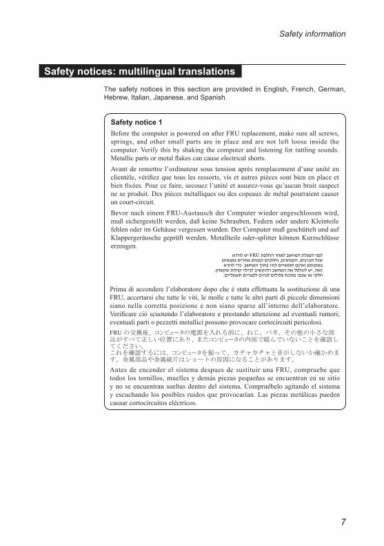
Safety notices: multilingual translationsThe safety notices in this section are provided in English, French, German, Hebrew, Italian, Japanese, and Spanish.
Safety notice 1 BeforethecomputerispoweredonafterFRUreplacement,makesureallscrews,springs, andother smallparts are inplace andarenot left loose inside thecomputer.Verifythisbyshakingthecomputerandlisteningforrattlingsounds.Metallicpartsormetalflakescancauseelectricalshorts.Avantderemettre l’ordinateursous tensionaprèsremplacementd’uneunitéenclientèle,vérifiezquetouslesressorts,visetautrespiècessontbienenplaceetbienfixées.Pourcefaire,secouezl’unitéetassurez-vousqu’aucunbruitsuspectneseproduit.Despiècesmétalliquesoudescopeauxdemétalpourraientcauseruncourt-circuit.BevornacheinemFRU-AustauschderComputerwiederangeschlossenwird,mußsichergestelltwerden,daßkeineSchrauben,FedernoderandereKleinteilefehlenoderimGehäusevergessenwurden.DerComputermußgeschütteltundaufKlappergeräuschegeprüftwerden.Metallteileoder-splitterkönnenKurzschlüsseerzeugen.
Primadiaccenderel’elaboratoredopocheéstataeffettuatalasostituzionediunaFRU,accertarsichetutteleviti,lemolleetuttelealtripartidipiccoledimensionisianonellacorrettaposizioneenonsianosparseall’internodell’elaboratore.Verificareciòscuotendol’elaboratoreeprestandoattenzioneadeventualirumori;eventualipartiopezzettimetallicipossonoprovocarecortocircuitipericolosi.
Antesdeencenderel sistemadespuesde sustituirunaFRU,compruebequetodos los tornillos,muellesydemáspiezaspequeñasseencuentranensusitioynoseencuentransueltasdentrodelsistema.Compruébeloagitandoelsistemayescuchandolosposiblesruidosqueprovocarían.Laspiezasmetálicaspuedencausarcortocircuitoseléctricos.
8
Lenovo ideapad FLEX 5-1470/Lenovo ideapad FLEX 5-1570 Hardware Maintenance Manual
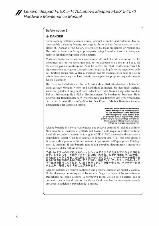
Safety notice 2
DANGERSomestandbybatteriescontainasmallamountofnickelandcadmium.Donotdisassembleastandbybattery, recharge it, throwit intofireorwater,orshort-circuit it.Disposeof thebatteryasrequiredbylocalordinancesorregulations.Useonlythebatteryintheappropriatepartslisting.Useofanincorrectbatterycanresultinignitionorexplosionofthebattery.Certainesbatteriesde secourscontiennentdunickel etducadmium.Ne lesdémontezpas,ne les rechargezpas,ne lesexposezni au feuni à l’eau.Nelesmettezpasencourt-circuit.Pour lesmettreau rebut,conformez-vousà laréglementationenvigueur.Lorsquevousremplacezlapiledesauvegardeoucelledel’horlogetempsréel,veillezàn’utiliserquelesmodèlescitésdanslalistedepiècesdétachéesadéquate.Unebatterieouunepileinappropriéerisquedeprendrefeuoud’exploser.DieBereitschaftsbatterie, die sich unter demDiskettenlaufwerk befindet,kanngeringeMengenNickelundCadmiumenthalten.Siedarfnichtzerlegt,wiederaufgeladen,kurzgeschlossen,oderFeueroderWasserausgesetztwerden.BeiderEntsorgungdieörtlichenBestimmungenfürSondermüllbeachten.BeimErsetzenderBereitschafts-oderSystembatterienurBatteriendesTypsverwenden,der inderErsatzteillisteaufgeführt ist.DerEinsatz falscherBatterienkannzuEntzündungoderExplosionführen.
Alcunebatteriedi riservacontengonounapiccolaquantitàdinichelecadmio.Nonsmontarle, ricaricarle,gettarlenel fuocoonell’acquanécortocircuitarle.Smaltirlesecondolanormativainvigore(DPR915/82,successivedisposizioniedisposizionilocali).Quandosisostituiscelabatteriadell’RTC(realtimeclock)olabatteriadisupporto,utilizzaresoltantoi tipi inseritinell’appropriatoCatalogoparti.L’impiegodiunabatterianonadattapotrebbedeterminare l’incendiool’esplosionedellabatteriastessa.
Algunasbateríasdereservacontienenunapequeñacantidaddeníquelycadmio.Nolasdesmonte,nirecargue,ni lasechealfuegooalaguanilascortocircuite.Deséchelas talcomodispone lanormativa local.Utilice sólobateríasqueseencuentrenenlalistadepiezas.Lautilizacióndeunabateríanoapropiadapuedeprovocarlaigniciónoexplosióndelamisma.

9
Safety information
Safety notice 3
DANGERThebatterypackcontainssmallamountsofnickel.Donotdisassembleit, throwitintofireorwater,orshort-circuitit.Disposeofthebatterypackasrequiredbylocalordinancesorregulations.Useonlythebatteryintheappropriatepartslistingwhenreplacingthebatterypack.Useofanincorrectbatterycanresultinignitionorexplosionofthebattery.Labatteriecontientdunickel.Neladémontezpas,nel’exposezniaufeuniàl’eau.Nelamettezpasencourt-circuit.Pour lamettreaurebut,conformez-vousà laréglementationenvigueur.Lorsquevousremplacezlabatterie,veillezàn’utiliserque lesmodèlescitésdans la listedepiècesdétachéesadéquate.Eneffet,unebatterieinappropriéerisquedeprendrefeuoud’exploser.Akkus enthalten geringeMengen vonNickel. Sie dürfen nicht zerlegt,wiederaufgeladen,kurzgeschlossen,oderFeueroderWasserausgesetztwerden.BeiderEntsorgungdieörtlichenBestimmungenfürSondermüllbeachten.BeimErsetzenderBatterienurBatteriendesTypsverwenden,derinderErsatzteillisteaufgeführtist.DerEinsatzfalscherBatterienkannzuEntzündungoderExplosionführen.
Labatteriacontienepiccolequantitàdinichel.Nonsmontarla,gettarlanelfuocoonell’acquanécortocircuitarla.Smaltirlasecondolanormativainvigore(DPR915/82,successivedisposizioniedisposizioni locali).Quandosisostituisce labatteria,utilizzaresoltantoitipiinseritinell’appropriatoCatalogoparti.L’impiegodiunabatterianonadattapotrebbedeterminare l’incendioo l’esplosionedellabatteriastessa.
Lasbaterías contienenpequeñas cantidadesdeníquel.No lasdesmonte,nirecargue,nilasechealfuegooalaguanilascortocircuite.Deséchelastalcomodisponelanormativalocal.Utilicesólobateríasqueseencuentrenenlalistadepiezasalsustituir labatería.Lautilizacióndeunabateríanoapropiadapuedeprovocarlaigniciónoexplosióndelamisma.

10
Lenovo ideapad FLEX 5-1470/Lenovo ideapad FLEX 5-1570 Hardware Maintenance Manual
Safety notice 4
DANGERThe lithiumbatterycancausea fire, anexplosion,ora severeburn.Donotrecharge it, removeitspolarizedconnector,disassembleit,heat itabove100°C(212°F),incinerateit,orexposeitscellcontentstowater.Disposeofthebatteryasrequiredbylocalordinancesorregulations.Useonlythebatteryintheappropriatepartslisting.Useofanincorrectbatterycanresultinignitionorexplosionofthebattery.Lapiledesauvegardecontientdulithium.Elleprésentedesrisquesd’incendie,d’explosionoudebrûluresgraves.Ne la rechargezpas, ne retirezpas sonconnecteurpolariséetne ladémontezpas.Nel’exposezpasàunetemperaturesupérieureà100°C,nelafaitespasbrûleretn’enexposezpaslecontenuàl’eau.Mettez lapileaurebutconformémentà laréglementationenvigueur.Unepileinappropriéerisquedeprendrefeuoud’exploser.DieSystembatterieisteineLithiumbatterie.Siekannsichentzünden,explodierenoder schwereVerbrennungenhervorrufen.BatteriendiesesTypsdürfennichtaufgeladen,zerlegt,über100Cerhitztoderverbranntwerden.Auchdarf ihrInhaltnichtmitWasser inVerbindunggebrachtoderderzur richtigenPolungangebrachteVerbindungssteckerentferntwerden.BeiderEntsorgungdieörtlichenBestimmungenfürSondermüllbeachten.BeimErsetzenderBatterienurBatteriendesTypsverwenden,derinderErsatzteillisteaufgeführtist.DerEinsatzfalscherBatterienkannzuEntzündungoderExplosionführen.
Labatteriadi supportoeunabatteria al litioepuo incendiarsi, esplodereoprocuraregraviustioni.Evitarediricaricarla,smontarneilconnettorepolarizzato,smontarla, riscaldarla aduna temperatura superiore ai100gradi centigradi,incendiarlaogettarla inacqua.Smaltirlasecondolanormativa invigore(DPR915/82,successivedisposizioniedisposizioni locali).L’impiegodiunabatterianonadattapotrebbedeterminarel’incendiool’esplosionedellabatteriastessa.
Labatería de repuesto es unabatería de litio ypuedeprovocar incendios,explosionesoquemadurasgraves.Nolarecargue,niquiteelconectorpolarizado,ni ladesmonte,nicalienteporencimade los100°C(212°F),ni la incinereniexpongael contenidode sus celdas al agua.Deséchela tal comodispone lanormativalocal.

11
Safety information
Safety notice 5IftheLCDbreaksandthefluidfrominsidetheLCDgetsintoyoureyesoronyourhands, immediatelywash theaffectedareaswithwaterat least for15minutes.Seekmedicalcareifanysymptomscausedbythefluidarepresentafterwashing.Silepanneaud’affichageàcristauxliquidessebriseetquevousrecevezdanslesyeuxousur lesmainsunepartiedufluide,rincez-lesabondammentpendantaumoinsquinzeminutes.Consultezunmédecinsidessymptômespersistentaprèslelavage.DieLeuchtstoffröhreimLCD-BildschirmenthältQuecksilber.BeiderEntsorgungdieörtlichenBestimmungen fürSondermüllbeachten.DerLCD-BildschirmbestehtausGlasundkannzerbrechen,wennerunsachgemäßbehandeltwirdoderderComputeraufdenBodenfällt.WennderBildschirmbeschädigtistunddiedarinbefindlicheFlüssigkeit inKontaktmitHautundAugengerät,solltendiebetroffenenStellenmindestens15MinutenmitWasserabgespültundbeiBeschwerdenanschließendeinArztaufgesuchtwerden.
Nelcasochecaso l’LCDsidovesse rompereed il liquido inessocontenutoentrasse incontattocongliocchio lemani, lavare immediatamente lepartiinteressateconacquacorrenteperalmeno15minuti;poiconsultareunmedicoseisintomidovesseropermanere.
SilaLCDserompeyelfluidodesuinteriorentraencontactoconsusojososusmanos, lave inmediatamente lasáreasafectadasconaguadurante15minutoscomomínimo.Obtengaatenciónmedicasisepresentaalgúnsíntomadelfluidodespuesdelavarse.

12
Lenovo ideapad FLEX 5-1470/Lenovo ideapad FLEX 5-1570 Hardware Maintenance Manual
Safety notice 6
DANGERToavoidshock,donotremovetheplasticcoverthatprotectsthelowerpartoftheinvertercard.Afind’éviter toutrisquedechocélectrique,neretirezpaslecacheenplastiqueprotégeantlapartieinférieuredelacarted’alimentation.AusSicherheitsgründendieKunststoffabdeckung, diedenunterenTeil derSpannungswandlerplatineumgibt,nichtentfernen.
Perevitarescosseelettriche,nonrimuoverelacoperturainplasticacheavvolgelaparteinferioredellaschedainvertitore.
Paraevitardescargas,noquitelacubiertadeplásticoquerodealapartebajadelatarjetainvertida.
Safety notice 7
DANGERThoughthemainbatterieshavelowvoltage,ashortedorgroundedbatterycanproduceenoughcurrenttoburnpersonnelorcombustiblematerials.Bienquelevoltagedesbatteriesprincipalessoitpeuélevé,lecourt-circuitoulamiseàlamassed’unebatteriepeutproduiresuffisammentdecourantpourbrûlerdesmatériauxcombustiblesoucauserdesbrûlurescorporellesgraves.ObwohlHauptbatterieneineniedrigeSpannunghaben,könnensiedochbeiKurzschlußoderErdunggenugStromabgeben,umbrennbareMaterialienzuentzündenoderVerletzungenbeiPersonenhervorzurufen.
Sebbene lebatteriedialimentazione sianoabassovoltaggio,unabatteria incortocircuitooamassapuòfornirecorrentesufficientedabruciarematerialicombustibilioprovocareustioniaitecnicidimanutenzione.
Aunquelasbateríasprincipalestienenunvoltajebajo,unabateríacortocircuitadaoconcontactoatierrapuedeproducir lacorrientesuficientecomoparaquemarmaterialcombustibleoprovocarquemadurasenelpersonal.
13
Safety information
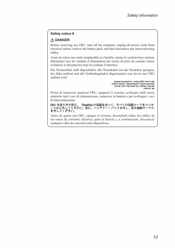
Safety notice 8
DANGERBeforeremovinganyFRU,turnoff thecomputer,unplugallpowercordsfromelectricaloutlets,removethebatterypack,andthendisconnectanyinterconnectingcables.Avantderetireruneunitéremplaçableenclientèle,mettezlesystèmehorstension,débrancheztouslescordonsd’alimentationdessoclesdeprisedecourant,retirezlabatterieetdéconnecteztouslescordonsd’interface.DieStromzufuhrmußabgeschaltet,alleStromkabelausderSteckdosegezogen,derAkkuentferntundalleVerbindungskabelabgenommensein,bevoreineFRUentferntwird.
Primadi rimuoverequalsiasiFRU,spegnere il sistema,scollegaredallepreseelettrichetuttiicavidialimentazione,rimuoverelabatteriaepoiscollegareicavidiinterconnessione.
AntesdequitarunaFRU,apagueel sistema,desenchufe todos loscablesdelas tomasdecorrienteeléctrica,quite labateríay,acontinuación,desconectecualquiercabledeconexiónentredispositivos.
14
Lenovo ideapad FLEX 5-1470/Lenovo ideapad FLEX 5-1570 Hardware Maintenance Manual
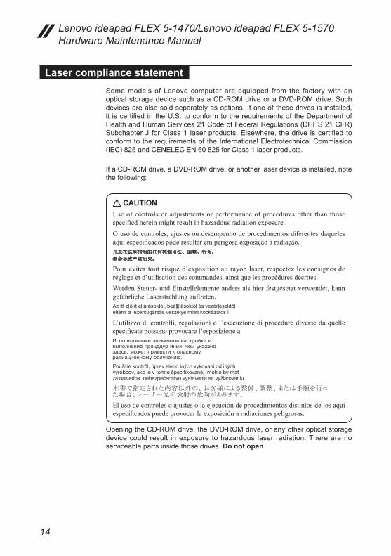
Laser compliance statementSome models of Lenovo computer are equipped from the factory with an optical storage device such as a CD-ROM drive or a DVD-ROM drive. Such devices are also sold separately as options. If one of these drives is installed, it is certified in the U.S. to conform to the requirements of the Department of Health and Human Services 21 Code of Federal Regulations (DHHS 21 CFR) Subchapter J for Class 1 laser products. Elsewhere, the drive is certified to conform to the requirements of the International Electrotechnical Commission (IEC) 825 and CENELEC EN 60 825 for Class 1 laser products.
If a CD-ROM drive, a DVD-ROM drive, or another laser device is installed, note the following:
CAUTIONUseofcontrolsoradjustmentsorperformanceofproceduresother than thosespecifiedhereinmightresultinhazardousradiationexposure.Ousodecontroles,ajustesoudesempenhodeprocedimentosdiferentesdaquelesaquiespecificadospoderesultaremperigosaexposiçãoàradiação.
Pouréviter tout risqued’expositionaurayon laser, respectez lesconsignesderéglageetd’utilisationdescommandes,ainsiquelesprocéduresdécrites.WerdenSteuer-undEinstellelementeandersalshierfestgesetztverwendet,kanngefährlicheLaserstrahlungauftreten.
L’utilizzodicontrolli,regolazioniol’esecuzionediprocedurediversedaquellespecificatepossonoprovocarel’esposizionea.
Elusodecontrolesoajustesolaejecucióndeprocedimientosdistintosdelosaquíespecificadospuedeprovocarlaexposiciónaradiacionespeligrosas.
Opening the CD-ROM drive, the DVD-ROM drive, or any other optical storage device could result in exposure to hazardous laser radiation. There are no serviceable parts inside those drives. Do not open.

15
Safety information
A CD-ROM drive, a DVD-ROM drive, or any other storage device installed may contain an embedded Class 3A or Class 3B laser diode. Note the following:
DANGEREmitsvisibleandinvisiblelaserradiationwhenopen.Donotstareintothebeam,donotviewdirectlywithoptical instruments,andavoiddirectexposure to thebeam.Radiação por raio laser ao abrir.Nãoolhe fixo no feixe de luz, não olhediretamentepormeiodeinstrumentosóticoseeviteexposiçãodiretacomofeixedeluz.
Rayonnement lasersicarterouvert.Évitezdefixer le faisceau,de le regarderdirectementavecdesinstrumentsoptiques,oudevousexposeraurayon.LaserstrahlungbeigeöffnetemGerät.NichtdirektoderüberoptischeInstrumenteindenLaserstrahlsehenunddenStrahlungsbereichmeiden.Kinyitáskor lézersugár !Ne nézzen bele se szabad szemmel, se optikaieszközökkel.Kerüljeasugárnyalábbalvalóérintkezést!Aprendo l’unitàvengonoemesse radiazioni laser.Non fissare il fascio,nonguardarlodirettamenteconstrumentiotticieevitarel’esposizionedirettaalfascio.
Radiaciónláseralabrir.Nomirefijamenteniexamineconinstrumentalópticoelhazdeluz.Evitelaexposicióndirectaalhaz.
16
Lenovo ideapad FLEX 5-1470/Lenovo ideapad FLEX 5-1570 Hardware Maintenance Manual
Important service information
This chapter presents the following important service information: • “Strategy for replacing FRUs” on page 16
– “Strategy for replacing a hard disk drive” on page 17– “Important notice for replacing a system board” on page 17
• “Important information about replacing RoHS compliant FRUs” on page 18
Important:BIOSanddevicedriverfixesarecustomer-installable.TheBIOSanddevicedriversarepostedonthecustomersupportsite:http://support.lenovo.com.
Strategy for replacing FRUs
Before replacing parts:Make sure that all software fixes, drivers, and BIOS downloads are installed before replacing any FRUs listed in this manual.After a system board is replaced, ensure that the latest BIOS is loaded to the system board before completing the service action. To download software fixes, drivers, and BIOS, follow the steps below:1. Go to http://support.lenovo.com.2. Enter the serial number or select a product or use Lenovo smart
downloading.3. Select the BIOS/Driver/Applications and download.4. Follow the directions on the screen and install the necessary software.

17
Important service information
Use the following strategy to prevent unnecessary expense for replacing and servicing FRUs:• If you are instructed to replace an FRU, but the replacement does not solve
the problem, reinstall the original FRU before you continue.• Some computers have both a processor board and a system board. If you
are instructed to replace either of them, and replacing one of them does not solve the problem, reinstall that board, and then replace the other one.
• If an adapter or a device consists of more than one FRU, any of the FRUs may be the cause of the error. Before replacing the adapter or device, remove the FRUs one by one to see if the symptoms change. Replace only the FRU that changed the symptoms.
Attention: The setup configuration on the computer you are servicing may have been customized. Running Automatic Configuration may alter the settings. Note the current configuration settings (using the View Configuration option); then, when service has been completed, verify that those settings remain in effect.
Strategy for replacing a hard disk driveAlways try to run a low-level format before replacing a hard disk drive. This will cause all customer data on the hard disk to be lost. Make sure that the customer has a current backup of the data before performing this action.Attention: The drive startup sequence in the computer you are servicing may have been changed. Be extremely careful during write operations such as copying, saving, or formatting. If you select an incorrect drive, data or programs can be overwritten.
Important notice for replacing a system board Some components mounted on a system board are very sensitive. Improper handling can cause damage to those components, and may cause a system malfunction.Attention: When handling a system board:• Do not drop the system board or apply any excessive force to it.• Avoid rough handling of any kind.• Avoid bending the system board and hard pushing to prevent cracking at
each BGA (Ball Grid Array) chipset.
18
Lenovo ideapad FLEX 5-1470/Lenovo ideapad FLEX 5-1570 Hardware Maintenance Manual
Important information about replacing RoHS compliant FRUs
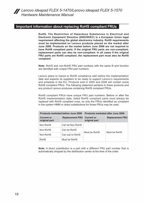
RoHS, The Restriction of Hazardous Substances in Electrical and Electronic Equipment Directive (2002/95/EC) is a European Union legal requirement affecting the global electronics industry. RoHS requirements must be implemented on Lenovo products placed on the market after June 2006. Products on the market before June 2006 are not required to have RoHS compliant parts. If the original FRU parts are non-compliant, replacement parts can also be non-compliant. In all cases if the original FRU parts are RoHS compliant, the replacement part must also be RoHS compliant.
Note: RoHS and non-RoHS FRU part numbers with the same fit and function are identified with unique FRU part numbers.
Lenovo plans to transit to RoHS compliance well before the implementation date and expects its suppliers to be ready to support Lenovo’s requirements and schedule in the EU. Products sold in 2005 and 2006 will contain some RoHS compliant FRUs. The following statement pertains to these products and any product Lenovo produces containing RoHS compliant FRUs.
RoHS compliant FRUs have unique FRU part numbers. Before or after the RoHS implementation date, failed RoHS compliant parts must always be replaced with RoHS compliant ones, so only the FRUs identified as compliant in the system HMM or direct substitutions for those FRUs may be used.
Products marketed before June 2006 Products marketed after June 2006 Current or original part
Replacement FRU Current or original part
Replacement FRU
Non-RoHS Can be Non-RoHS
Must be RoHS Must be RoHSNon-RoHS Can be RoHS
Non-RoHS Can sub to RoHS
RoHS Must be RoHS
Note: A direct substitution is a part with a different FRU part number that is automatically shipped by the distribution center at the time of the order.

19
General checkout
General checkout
This chapter presents the following information:• “What to do first” on page 20• “Power system checkout” on page 21
Before you go to the checkout, make sure to read the following important notes:
Important notes:• Onlycertifiedtrainedpersonnelcanservicethecomputer.• BeforereplacinganyFRU,readtheentirepageonremovingandreplacingFRUs.
• CarefullyremovescrewsforreusewhenreplacingFRUs.• Beextremelycarefulduringsuchwriteoperationsascopying,saving,orformatting.Drives in the computer thatyouare servicing sequencemighthavebeenaltered. Ifyouselectan incorrectdrive,dataorprogramsmightbeoverwritten.
• ReplaceanFRUonlywithanotherFRUof thecorrectmodel.WhenyoureplaceanFRU,makesurethatthemachinemodelandtheFRUpartnumberarecorrectbyreferringtotheFRUpartslist.
• AnFRUshouldnotbereplacedjustbecauseofasingle,unreproduciblefailure.Singlefailurescanoccurforavarietyofreasonsthathavenothingtodowithahardwaredefect,suchascosmicradiation,electrostaticdischarge,orsoftwareerrors.ConsiderreplacinganFRUonlywhenaproblemrecurs.IfyoususpectthatanFRUisdefective,cleartheerrorlogsandrunthetestagain.Iftheerrordoesnotrecur,donotreplacetheFRU.
• BecarefulnottoreplaceanondefectiveFRU.
20
Lenovo ideapad FLEX 5-1470/Lenovo ideapad FLEX 5-1570 Hardware Maintenance Manual
What to do firstWhen you do return an FRU, you must include the following information in the parts exchange form or parts return form that you attach to it:1. Name and phone number of servicer2. Date of service3. Date on which the machine failed4. Date of purchase5. Procedure index and page number in which the failing FRU was detected 6. Failing FRU name and part number7. Machine type, model number, and serial number8. Customer’s name and address
Note for warranty: During the warranty period, the customer may be responsible for repair costs if the computer damage was caused by misuse, accident, modification, unsuitable physical or operating environment, or improper maintenance by the customer.The following is a list of some common items that are not covered under warranty and some symptoms that might indicate that the system was subjected to stress beyond normal use.Before checking problems with the computer, determine whether the damage is covered under the warranty by referring to the following list:
The following are not covered under warranty: • LCD panel cracked from the application of excessive force or from being
dropped• Scratched (cosmetic) parts• Distortion, deformation, or discoloration of the cosmetic parts• Plastic parts, latches, pins, or connectors that have been cracked or broken
by excessive force• Damage caused by liquid spilled into the system• Damage caused by the improper insertion of a PC Card or the installation of
an incompatible card• Improper disk insertion or use of an optical drive • Diskette drive damage caused by pressure on the diskette drive cover,
foreign material in the drive, or the insertion of a diskette with multiple labels • Damaged or bent diskette eject button• Fuses blown by attachment of a nonsupported device• Forgotten computer password (making the computer unusable)• Sticky keys caused by spilling a liquid onto the keyboard• Use of an incorrect AC adapter on laptop products
The following symptoms might indicate damage caused by nonwarranted activities: • Missing parts might be a symptom of unauthorized service or modification. • If the spindle of a hard disk drive becomes noisy, it may have been subjected
to excessive force, or dropped.
21
General checkout
Power system checkout
To verify a symptom, follow the steps below:1. Turn off the computer.2. Connect the AC adapter.3. Make sure that power is supplied when you turn on the computer.4. Turn off the computer.5. Disconnect the AC adapter.6. Make sure that the battery pack supplies power when you turn on the
computer.
If you suspect a power problem, see the appropriate power supply checkout:• “Checking the AC adapter” on page 21• “Checking operational charging” on page 22
Checking the AC adapter You are here because the computer fails only when the AC adapter is used. • If the power-on indicator does not turn on, check the power cord of the AC
adapter for correct continuity and installation.• If the computer does not charge during operation, go to “Checking
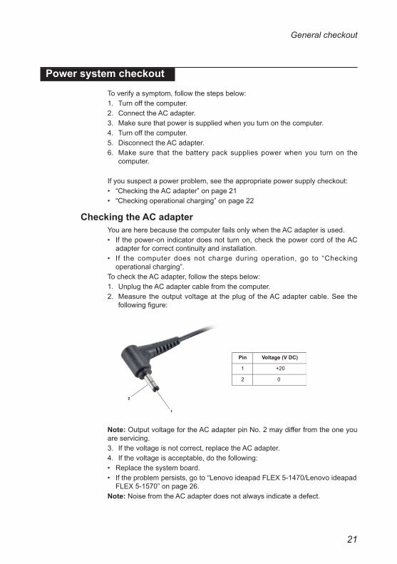
operational charging”.To check the AC adapter, follow the steps below:1. Unplug the AC adapter cable from the computer.2. Measure the output voltage at the plug of the AC adapter cable. See the
following figure:
1
2
Voltage (V DC)
+20
0
Pin
1
2
Note: Output voltage for the AC adapter pin No. 2 may differ from the one you are servicing.3. If the voltage is not correct, replace the AC adapter.4. If the voltage is acceptable, do the following: • Replace the system board.• If the problem persists, go to “Lenovo ideapad FLEX 5-1470/Lenovo ideapad
FLEX 5-1570” on page 26.Note: Noise from the AC adapter does not always indicate a defect.
22
Lenovo ideapad FLEX 5-1470/Lenovo ideapad FLEX 5-1570 Hardware Maintenance Manual
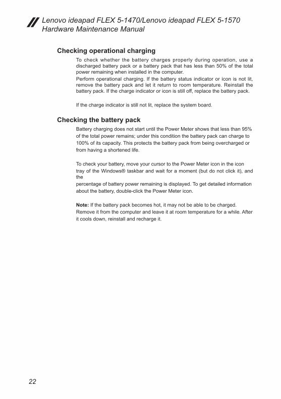
Checking operational chargingTo check whether the battery charges properly during operation, use a discharged battery pack or a battery pack that has less than 50% of the total power remaining when installed in the computer. Perform operational charging. If the battery status indicator or icon is not lit, remove the battery pack and let it return to room temperature. Reinstall the battery pack. If the charge indicator or icon is still off, replace the battery pack.
If the charge indicator is still not lit, replace the system board.
Checking the battery packBattery charging does not start until the Power Meter shows that less than 95%of the total power remains; under this condition the battery pack can charge to100% of its capacity. This protects the battery pack from being overcharged orfrom having a shortened life.
To check your battery, move your cursor to the Power Meter icon in the icontray of the Windows® taskbar and wait for a moment (but do not click it), and thepercentage of battery power remaining is displayed. To get detailed informationabout the battery, double-click the Power Meter icon.
Note: If the battery pack becomes hot, it may not be able to be charged.Remove it from the computer and leave it at room temperature for a while. Afterit cools down, reinstall and recharge it.
23
Related service information
Related service information
This chapter presents the following information:• “Restoring the factory contents by using OneKey Recovery” on page 23• “Passwords” on page 24• “Power management” on page 25
Restoring the factory contents by using OneKey Recovery
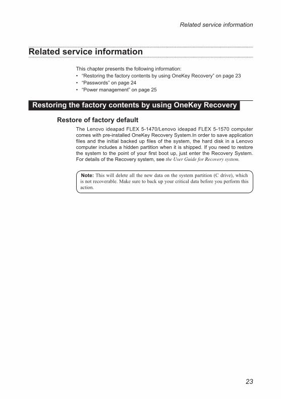
Restore of factory defaultThe Lenovo ideapad FLEX 5-1470/Lenovo ideapad FLEX 5-1570 computer comes with pre-installed OneKey Recovery System.In order to save application files and the initial backed up files of the system, the hard disk in a Lenovo computer includes a hidden partition when it is shipped. If you need to restore the system to the point of your first boot up, just enter the Recovery System. For details of the Recovery system, see the User Guide for Recovery system.
Note:Thiswilldeleteall thenewdataonthesystempartition(Cdrive),whichisnotrecoverable.Makesuretobackupyourcriticaldatabeforeyouperformthisaction.

24
Lenovo ideapad FLEX 5-1470/Lenovo ideapad FLEX 5-1570 Hardware Maintenance Manual
Passwords
As many as three passwords may be needed for any Lenovo computer: the power-on password (POP), the hard disk password (HDP), and the supervisor password.If any of these passwords has been set, a prompt for it appears on the screen whenever the computer is turned on. The computer does not start until the password is entered.
Power-on passwordA power-on password (POP) protects the system from being powered on by an unauthorized person. The password must be entered before an operating system can be booted.
Hard-disk passwordThere are two hard-disk passwords (HDPs):+ User HDP - for the user+ Master HDP - for the system administrator, who can use it to get access to the hard disk drive even if the user has changed the user HDPAttention: If the user HDP has been forgotten, check whether a master HDP has been set. If it has, it can be used for access to the hard disk drive. If no master HDP is available, neither Lenovo nor Lenov authorized service technicians provide any services to reset either the user or the master HDP, or to recover data from the hard disk drive. The hard disk drive can be replaced for a scheduled fee.
Supervisor passwordA supervisor password protects the system information stored in the BIOS. The user must enter the supervisor password to get access to the BIOS and change the system configuration.
Attention: If you forget the password, there is no service procedure to reset the password. The system board must be replaced for a scheduled fee.
25
Related service information
Power management
Note: Power management modes are not supported for an APM operating system.
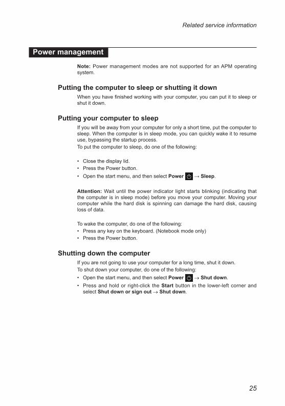
Putting the computer to sleep or shutting it downWhen you have finished working with your computer, you can put it to sleep or shut it down.
Putting your computer to sleepIf you will be away from your computer for only a short time, put the computer to sleep. When the computer is in sleep mode, you can quickly wake it to resume use, bypassing the startup process. To put the computer to sleep, do one of the following:
• Close the display lid.• Press the Power button.• Open the start menu, and then select Power → Sleep.
Attention: Wait until the power indicator light starts blinking (indicating that the computer is in sleep mode) before you move your computer. Moving your computer while the hard disk is spinning can damage the hard disk, causing loss of data.
To wake the computer, do one of the following:• Press any key on the keyboard. (Notebook mode only)• Press the Power button.
Shutting down the computerIf you are not going to use your computer for a long time, shut it down.To shut down your computer, do one of the following:• Open the start menu, and then select Power → Shut down.• Press and hold or right-click the Start button in the lower-left corner and
select Shut down or sign out → Shut down.
26
Lenovo ideapad FLEX 5-1470/Lenovo ideapad FLEX 5-1570 Hardware Maintenance Manual
Lenovo ideapad FLEX 5-1470/Lenovo ideapad FLEX 5-1570
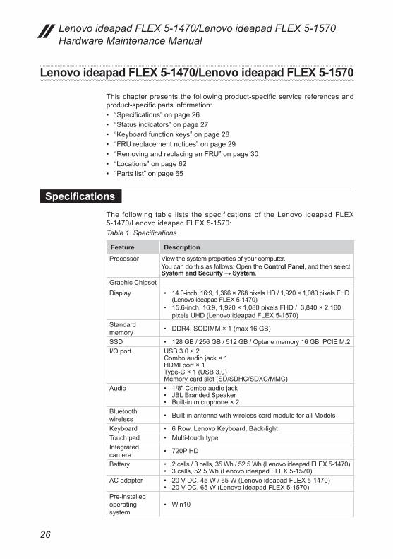
This chapter presents the following product-specific service references and product-specific parts information:• “Specifications” on page 26• “Status indicators” on page 27• “Keyboard function keys” on page 28• “FRU replacement notices” on page 29• “Removing and replacing an FRU” on page 30• “Locations” on page 62• “Parts list” on page 65
SpecificationsThe following table lists the specifications of the Lenovo ideapad FLEX 5-1470/Lenovo ideapad FLEX 5-1570:Table 1. Specifications
Feature DescriptionProcessor View the system properties of your computer.
You can do this as follows: Open the Control Panel, and then select System and Security → System.
Graphic Chipset Display • 14.0-inch, 16:9, 1,366 × 768 pixels HD / 1,920 × 1,080 pixels FHD
(Lenovo ideapad FLEX 5-1470)• 15.6-inch, 16:9, 1,920 × 1,080 pixels FHD / 3,840 × 2,160
pixels UHD (Lenovo ideapad FLEX 5-1570)Standard memory • DDR4, SODIMM × 1 (max 16 GB)
SSD • 128 GB / 256 GB / 512 GB / Optane memory 16 GB, PCIE M.2I/O port USB 3.0 × 2
Combo audio jack × 1HDMI port × 1Type-C × 1 (USB 3.0) Memory card slot (SD/SDHC/SDXC/MMC)
Audio • 1/8" Combo audio jack• JBL Branded Speaker• Built-in microphone × 2
Bluetooth wireless • Built-in antenna with wireless card module for all Models
Keyboard • 6 Row, Lenovo Keyboard, Back-lightTouch pad • Multi-touch typeIntegrated camera • 720P HD
Battery • 2 cells / 3 cells, 35 Wh / 52.5 Wh (Lenovo ideapad FLEX 5-1470)• 3 cells, 52.5 Wh (Lenovo ideapad FLEX 5-1570)
AC adapter • 20 V DC, 45 W / 65 W (Lenovo ideapad FLEX 5-1470)• 20 V DC, 65 W (Lenovo ideapad FLEX 5-1570)
Pre-installed operating system
• Win10

27
Lenovo ideapad FLEX 5-1470/Lenovo ideapad FLEX 5-1570
Status indicatorsThe system status indicators below show the computer status:
1
2
Table 2. Status indicators
Indicator Indicator status Chargestatus Meaning
Battery status
indicator1
On (solid white) Charging The battery has more than 80% charge.
On (solid amber) Discharging The battery has between 5% and
20% charge.
Blinking slowly (white) Charging
The battery has between 20% and 80% charge. When the battery reaches 80% charge, the light will stop blinking. However, charging will continue until the battery is fully charged.
Blinking slowly (amber) Charging
The battery has less than 20% charge. When the battery charge reaches 20%, the blinking color will change to white.
Blinking quickly (amber) Discharging The battery has less than 5% charge.
Off Discharging The battery has more than 20% charge.Power status
indicator2
On (solid white) --- The computer is powered on.Blinking --- The computer is in sleep mode.
Off --- The computer is powered off.
28
Lenovo ideapad FLEX 5-1470/Lenovo ideapad FLEX 5-1570 Hardware Maintenance Manual
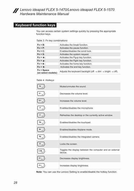
Keyboard function keysYou can access certain system settings quickly by pressing the appropriate function keys.
Table 3. Fn key combinations
Fn + B: Activates the break function.Fn + P: Activates the pause function.Fn + C: Enables/disables the scroll lock.Fn + S: Activates the system request.Fn + : Activates the Pgup key function. Fn + : Activates the Pgdn key function. Fn + : Activates the home key function. Fn + : Activates the end key function. Fn + Space (on select models): Adjusts the keyboard backlight (off → dim → bright → off).
Table 4. Hotkeys
: Mutes/unmutes the sound.
: Decreases the volume level.
: Increases the volume level.
: Enables/disables the microphone.
: Refreshes the desktop or the currently active window.
: Enables/disables the touchpad.
: Enables/disables Airplane mode.
: Enables/disables the integrated camera.
: Locks the screen.
: Toggles the display between the computer and an external device.
: Decreases display brightness.
: Increases display brightness.
Note: You can use the Lenovo Setting to enable/disable the hotkey function.
29
Lenovo ideapad FLEX 5-1470/Lenovo ideapad FLEX 5-1570
FRU replacement notices
This section presents notices related to removing and replacing parts. Read this section carefully before replacing any FRU.
Screw notices Loose screws can cause a reliability problem. In the Lenovo computer, this problem is addressed with special nylon-coated screws that have the following characteristics:• They maintain tight connections.• They do not easily come loose, even with shock or vibration.• They are harder to tighten.
Do the following when you service this machine: • Keep the screw kit in your tool bag.• Carefully remove screws for reuse when replacing FRUs.• Use a torque screwdriver if you have one.
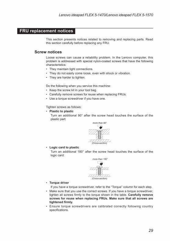
Tighten screws as follows:• Plastic to plastic Turn an additional 90° after the screw head touches the surface of the
plastic part:more than 90°
(Cross-section)
• Logic card to plastic Turn an additional 180° after the screw head touches the surface of the
logic card: more than 180°
(Cross-section)
• Torque driver If you have a torque screwdriver, refer to the “Torque” column for each step.• Make sure that you use the correct screws. If you have a torque screwdriver,
tighten all screws firmly to the torque shown in the table. Carefully remove screws for reuse when replacing FRUs. Make sure that all screws are tightened firmly.
• Ensure torque screwdrivers are calibrated correctly following country specifications.

30
Lenovo ideapad FLEX 5-1470/Lenovo ideapad FLEX 5-1570 Hardware Maintenance Manual
Removing and replacing an FRUThis section presents exploded figures with the instructions to indicate how to remove and replace the FRU. Make sure to observe the following general rules:1. Do not attempt to service any computer unless you have been trained and
certified. An untrained person runs the risk of damaging parts.2. Before replacing any FRU, review “FRU replacement notices” on page 29.3. Begin by removing any FRUs that have to be removed before the failing
FRU. Any of such FRUs are listed at the top of the page. Remove them in the order in which they are listed.
4. Follow the correct sequence in the steps to remove the FRU, as given in the figures by the numbers in square callouts.
5. When turning a screw to replace an FRU, turn it in the direction as given by the arrow in the figure.
6. When removing the FRU, move it in the direction as given by the arrow in the figure.
7. To put the new FRU in place, reverse the removal procedures and follow any of the notes that pertain to replacement. For information about connecting and arranging internal cables, see “Locations” on page 62.
8. When replacing an FRU, use the correct screw as shown in the procedures.
DANGERBeforeremovinganyFRU, turnoff thecomputer,unplugallpowercordsfromelectrical outlets, remove thebatterypack, and thendisconnect anyof theinterconnectingcables.
Attention: After replacing an FRU, do not turn on the computer until you have made sure that all screws, springs, and other small parts are in place and none are loose inside the computer. Verify this by shaking the computer gently and listening for rattling sounds. Metallic parts or metal flakes can cause electrical short circuits.
Attention: The system board is sensitive to, and can be damaged by, electrostatic discharge. Before touching it, establish personal grounding by touching a ground point with one hand or using an electrostatic discharge (ESD) strap (P/N 6405959) to remove potential shock reasons.
Notes:• This manual applies to the following models: Lenovo ideapad FLEX 5-1470/
Lenovo ideapad FLEX 5-1570.• The illustrations used in this manual are for Lenovo ideapad FLEX 5-1470
unless otherwise stated.

31
Lenovo ideapad FLEX 5-1470/Lenovo ideapad FLEX 5-1570
1010 Base cover
Figure 1. Removal steps of base cover
Remove the screws 1.
1
1
1
1
1
1
1
1
1
1
Step Screw (quantity) Color Torque
1 M2.0 x 6.0 mm, Phillips-head, nylok-coated (10) LOW TO UPPER
Black/Silver
1.0-1.5 kgf*cm
Remove the base cover 2.
2
32
Lenovo ideapad FLEX 5-1470/Lenovo ideapad FLEX 5-1570 Hardware Maintenance Manual
Note: Applying labels to the base coverIf you see the following labels on base cover, it needs to be peeled off from the old base cover, and put on the new base cover.a OS labelb Indonesia labelc WLAN labeld BT labele China Office label
For some models, you also need to apply one or two FCC labels. Check the old base cover; if it has one or two FCC labels, find duplicates of them in the label kit and apply them to the new base cover.
For the location of each label, refer to the following figure:
33
Lenovo ideapad FLEX 5-1470/Lenovo ideapad FLEX 5-1570
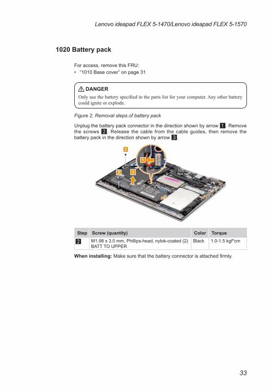
1020 Battery pack
For access, remove this FRU:• “1010 Base cover” on page 31
DANGEROnlyusethebatteryspecifiedinthepartslistforyourcomputer.Anyotherbatterycouldigniteorexplode.
Figure 2. Removal steps of battery pack
Unplug the battery pack connector in the direction shown by arrow 1. Remove the screws 2. Release the cable from the cable guides, then remove the battery pack in the direction shown by arrow 3.
2
2
1
3
Step Screw (quantity) Color Torque
2 M1.98 x 3.0 mm, Phillips-head, nylok-coated (2) BATT TO UPPER
Black 1.0-1.5 kgf*cm
When installing: Make sure that the battery connector is attached firmly.
34
Lenovo ideapad FLEX 5-1470/Lenovo ideapad FLEX 5-1570 Hardware Maintenance Manual
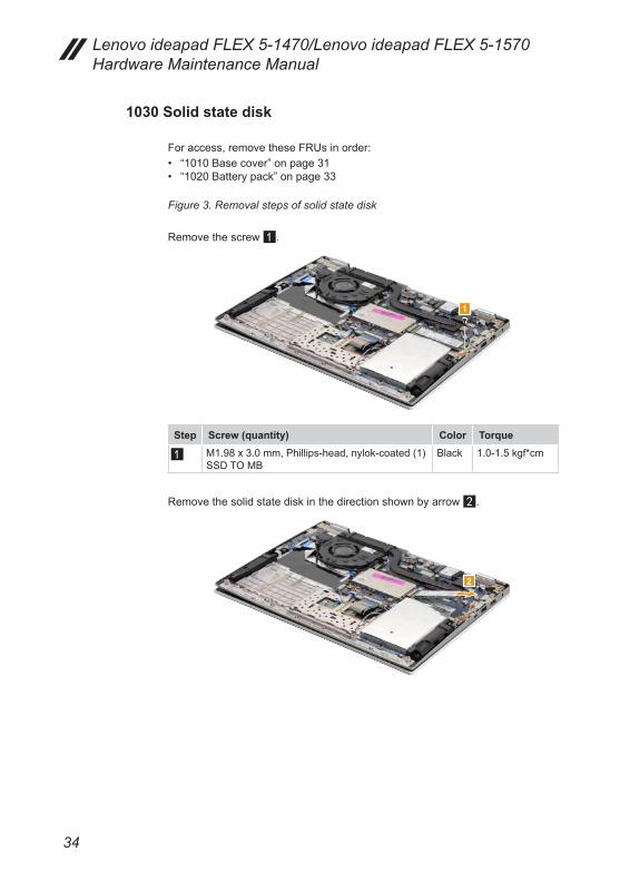
1030 Solid state disk
For access, remove these FRUs in order:• “1010 Base cover” on page 31• “1020 Battery pack” on page 33
Figure 3. Removal steps of solid state disk
Remove the screw 1.
1
Step Screw (quantity) Color Torque
1 M1.98 x 3.0 mm, Phillips-head, nylok-coated (1)SSD TO MB
Black 1.0-1.5 kgf*cm
Remove the solid state disk in the direction shown by arrow 2.
2
35
Lenovo ideapad FLEX 5-1470/Lenovo ideapad FLEX 5-1570
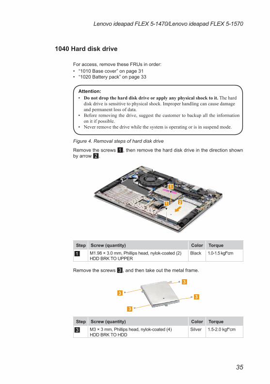
1040 Hard disk drive
For access, remove these FRUs in order:• “1010 Base cover” on page 31• “1020 Battery pack” on page 33
Attention:• Donotdroptheharddiskdriveorapplyanyphysicalshocktoit.Thehard
diskdriveissensitivetophysicalshock.Improperhandlingcancausedamageandpermanentlossofdata.
• Beforeremovingthedrive,suggestthecustomertobackupalltheinformationonitifpossible.
• Neverremovethedrivewhilethesystemisoperatingorisinsuspendmode.
Figure 4. Removal steps of hard disk drive
Remove the screws 1, then remove the hard disk drive in the direction shown by arrow 2.
1
1 2
Step Screw (quantity) Color Torque
1 M1.98 × 3.0 mm, Phillips head, nylok-coated (2) HDD BRK TO UPPER
Black 1.0-1.5 kgf*cm
Remove the screws 3, and then take out the metal frame.
3
3
3
3
Step Screw (quantity) Color Torque
3 M3 × 3 mm, Phillips head, nylok-coated (4) HDD BRK TO HDD
Silver 1.5-2.0 kgf*cm

36
Lenovo ideapad FLEX 5-1470/Lenovo ideapad FLEX 5-1570 Hardware Maintenance Manual
1050 PCI Express Mini Card for wireless LAN
For access, remove these FRUs in order:• “1010 Base cover” on page 31• “1020 Battery pack” on page 33
Important: The preinstalled WLAN module may only be replaced with a Lenovo approved module in order to comply with FCC and IC regulations. Refer to “Table 5. Parts list—Overall” on page 67 for Lenovo part numbers for the approved modules.
Figure 5. Removal steps of PCI Express Mini Card for wireless LAN
Peel off the sponge on the card 1.
1
37
Lenovo ideapad FLEX 5-1470/Lenovo ideapad FLEX 5-1570
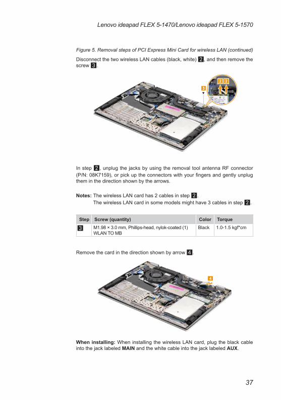
Figure 5. Removal steps of PCI Express Mini Card for wireless LAN (continued)
Disconnect the two wireless LAN cables (black, white) 2, and then remove the screw 3.
2 23
In step 2, unplug the jacks by using the removal tool antenna RF connector (P/N: 08K7159), or pick up the connectors with your fingers and gently unplug them in the direction shown by the arrows.
Notes: The wireless LAN card has 2 cables in step 2. The wireless LAN card in some models might have 3 cables in step 2.
Step Screw (quantity) Color Torque
3 M1.98 × 3.0 mm, Phillips-head, nylok-coated (1) WLAN TO MB
Black 1.0-1.5 kgf*cm
Remove the card in the direction shown by arrow 4.
4
When installing: When installing the wireless LAN card, plug the black cable into the jack labeled MAIN and the white cable into the jack labeled AUX.
38
Lenovo ideapad FLEX 5-1470/Lenovo ideapad FLEX 5-1570 Hardware Maintenance Manual
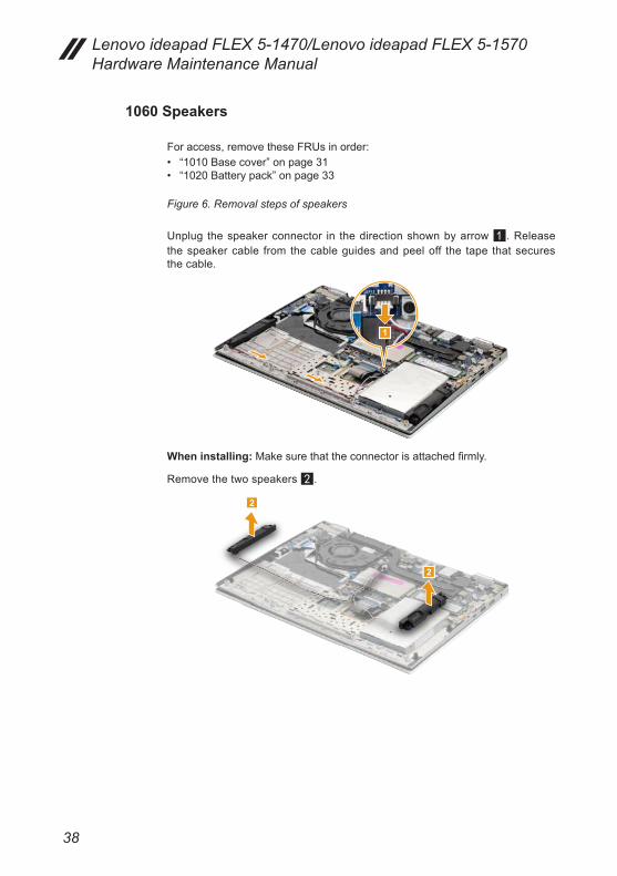
1060 Speakers
For access, remove these FRUs in order:• “1010 Base cover” on page 31• “1020 Battery pack” on page 33
Figure 6. Removal steps of speakers
Unplug the speaker connector in the direction shown by arrow 1. Release the speaker cable from the cable guides and peel off the tape that secures the cable.
1
When installing: Make sure that the connector is attached firmly.
Remove the two speakers 2.
2
2
39
Lenovo ideapad FLEX 5-1470/Lenovo ideapad FLEX 5-1570
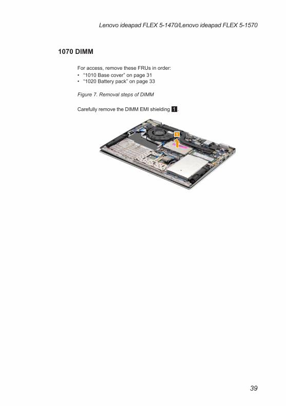
1070 DIMM
For access, remove these FRUs in order:• “1010 Base cover” on page 31• “1020 Battery pack” on page 33
Figure 7. Removal steps of DIMM
Carefully remove the DIMM EMI shielding 1.
1
40
Lenovo ideapad FLEX 5-1470/Lenovo ideapad FLEX 5-1570 Hardware Maintenance Manual
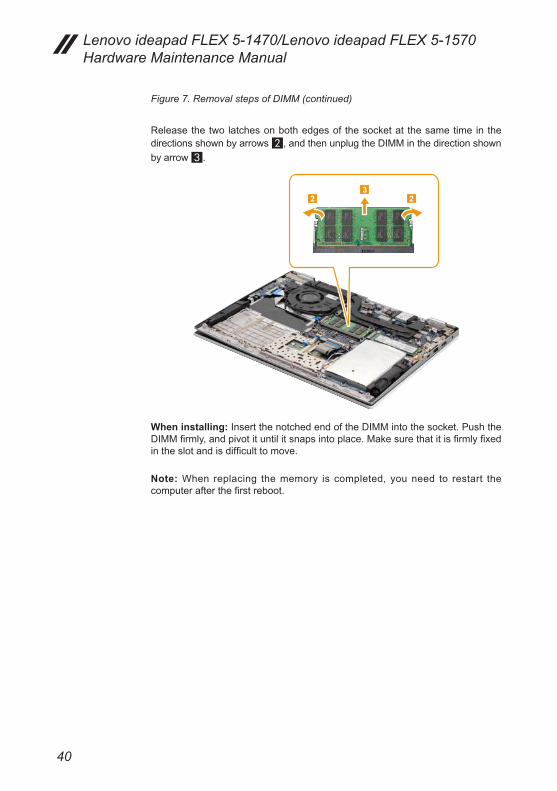
Figure 7. Removal steps of DIMM (continued)
Release the two latches on both edges of the socket at the same time in the directions shown by arrows 2, and then unplug the DIMM in the direction shown by arrow 3.
2 23
When installing: Insert the notched end of the DIMM into the socket. Push the DIMM firmly, and pivot it until it snaps into place. Make sure that it is firmly fixed in the slot and is difficult to move.
Note: When replacing the memory is completed, you need to restart the computer after the first reboot.

41
Lenovo ideapad FLEX 5-1470/Lenovo ideapad FLEX 5-1570
1080 Fan and Heat Sink assembly
For access, remove these FRUs in order:• “1010 Base cover” on page 31• “1020 Battery pack” on page 33
Figure 8. Removal steps of fan and heat sink assembly
Remove the screws 1.
1 1
11
1
Step Screw (quantity) Color Torque
1 M1.98 x 3.0 mm, Phillips-head, nylok-coated (5) THERMAL MODULE TO CPU BRK/THERMAL MODULE TO GPU BRK (for DIS only)
Black 1.0-1.5 kgf*cm

42
Lenovo ideapad FLEX 5-1470/Lenovo ideapad FLEX 5-1570 Hardware Maintenance Manual
Figure 8. Removal steps of fan and heat sink assembly (continued)
Remove the heat sink module in the direction shown by arrow 2.
2
Attention: Do not handle the heat sink assembly roughly. Improper handling can cause distortion or deformation and imperfect contact with components.
a b
When installing: Before you attach the fan assembly to the computer, apply thermal grease, at an amount of 0.2 grams, to parts a and b shown in the figure above. Either too much or too little grease application can cause a thermal problem due to imperfect contact with a component.

43
Lenovo ideapad FLEX 5-1470/Lenovo ideapad FLEX 5-1570
Figure 8. Removal steps of fan and heat sink assembly (continued)
Unplug the fan connector in the direction shown by arrow 3. Remove the screws 4. Release the LCD cable from the cable guides.
44
3
Step Screw (quantity) Color Torque
4 M1.98 × 3.0 mm, Phillips head, nylok-coated (2) FAN TO upper
Black 1.0-1.5 kgf*cm
When installing: Make sure that the connector is attached firmly.
Remove the fan 5.
5
44
Lenovo ideapad FLEX 5-1470/Lenovo ideapad FLEX 5-1570 Hardware Maintenance Manual
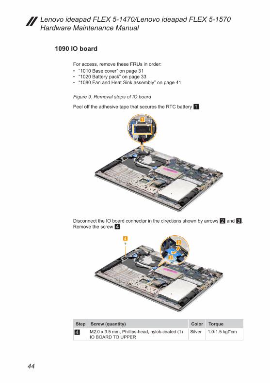
1090 IO board
For access, remove these FRUs in order:• “1010 Base cover” on page 31• “1020 Battery pack” on page 33• “1080 Fan and Heat Sink assembly” on page 41
Figure 9. Removal steps of IO board
Peel off the adhesive tape that secures the RTC battery 1.
1
Disconnect the IO board connector in the directions shown by arrows 2 and 3. Remove the screw 4.
42
3
Step Screw (quantity) Color Torque
4 M2.0 x 3.5 mm, Phillips-head, nylok-coated (1) IO BOARD TO UPPER
Silver 1.0-1.5 kgf*cm

45
Lenovo ideapad FLEX 5-1470/Lenovo ideapad FLEX 5-1570
Figure 9. Removal steps of IO board (continued)
Remove the IO board 5.
5
Unplug the RTC battery connector in the direction shown by arrow 6, then remove the RTC battery.
6
46
Lenovo ideapad FLEX 5-1470/Lenovo ideapad FLEX 5-1570 Hardware Maintenance Manual
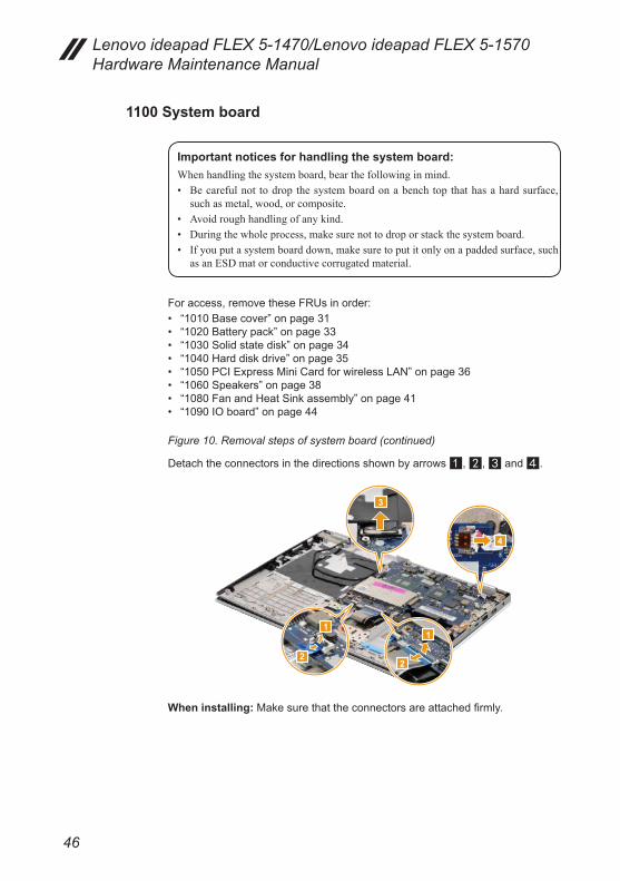
1100 System board
Important notices for handling the system board:Whenhandlingthesystemboard,bearthefollowinginmind.• Becarefulnot todropthesystemboardonabenchtopthathasahardsurface,
suchasmetal,wood,orcomposite.• Avoidroughhandlingofanykind.• Duringthewholeprocess,makesurenottodroporstackthesystemboard.• Ifyouputasystemboarddown,makesuretoputitonlyonapaddedsurface,such
asanESDmatorconductivecorrugatedmaterial.
For access, remove these FRUs in order:• “1010 Base cover” on page 31• “1020 Battery pack” on page 33• “1030 Solid state disk” on page 34• “1040 Hard disk drive” on page 35• “1050 PCI Express Mini Card for wireless LAN” on page 36• “1060 Speakers” on page 38• “1080 Fan and Heat Sink assembly” on page 41• “1090 IO board” on page 44
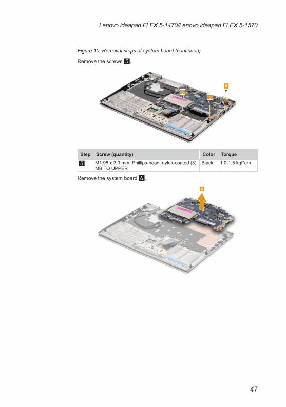
Figure 10. Removal steps of system board (continued)
Detach the connectors in the directions shown by arrows 1, 2, 3 and 4.
1
2
1
2
3
4
When installing: Make sure that the connectors are attached firmly.
47
Lenovo ideapad FLEX 5-1470/Lenovo ideapad FLEX 5-1570
Figure 10. Removal steps of system board (continued)
Remove the screws 5.
55
5
Step Screw (quantity) Color Torque
5 M1.98 x 3.0 mm, Phillips-head, nylok-coated (3) MB TO UPPER
Black 1.0-1.5 kgf*cm
Remove the system board 6.
6

48
Lenovo ideapad FLEX 5-1470/Lenovo ideapad FLEX 5-1570 Hardware Maintenance Manual
1110 Upper case
For access, remove these FRUs in order:• “1010 Base cover” on page 31• “1020 Battery pack” on page 33• “1030 Solid state disk” on page 34• “1040 Hard disk drive” on page 35• “1050 PCI Express Mini Card for wireless LAN” on page 36• “1060 Speakers” on page 38• “1080 Fan and Heat Sink assembly” on page 41• “1090 IO board” on page 44• “1100 System board” on page 46
Figure 11. Removal steps of upper case
Remove the screws 1.
1
1
1
1
Step Screw (quantity) Color Torque
1 M2.5 × 4.0 mm, Phillips-head, nylok-coated (4) HINGE BRK TO UPPER
Silver 1.5-2.0 kgf*cm
49
Lenovo ideapad FLEX 5-1470/Lenovo ideapad FLEX 5-1570
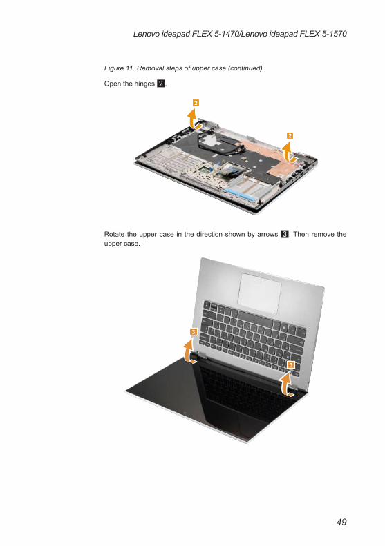
Figure 11. Removal steps of upper case (continued)
Open the hinges 2.
2
2
Rotate the upper case in the direction shown by arrows 3. Then remove the upper case.
3
3

50
Lenovo ideapad FLEX 5-1470/Lenovo ideapad FLEX 5-1570 Hardware Maintenance Manual
1120 DC-in cable
For access, remove these FRUs in order:• “1010 Base cover” on page 31• “1020 Battery pack” on page 33• “1030 Solid state disk” on page 34• “1040 Hard disk drive” on page 35• “1050 PCI Express Mini Card for wireless LAN” on page 36• “1060 Speakers” on page 38• “1080 Fan and Heat Sink assembly” on page 41• “1090 IO board” on page 44• “1100 System board” on page 46• “1110 Upper case” on page 48
Figure 12. Removal steps of DC-in cable
Remove the DC-in cable in the direction shown by arrow 1.
1
51
Lenovo ideapad FLEX 5-1470/Lenovo ideapad FLEX 5-1570
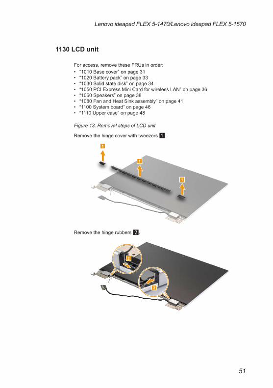
1130 LCD unit
For access, remove these FRUs in order:• “1010 Base cover” on page 31• “1020 Battery pack” on page 33• “1030 Solid state disk” on page 34• “1050 PCI Express Mini Card for wireless LAN” on page 36• “1060 Speakers” on page 38• “1080 Fan and Heat Sink assembly” on page 41• “1100 System board” on page 46• “1110 Upper case” on page 48
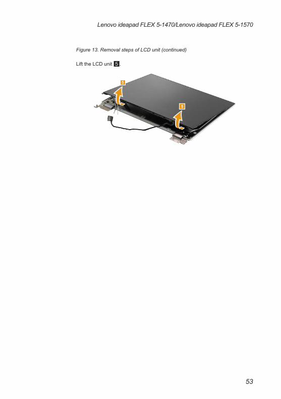
Figure 13. Removal steps of LCD unit
Remove the hinge cover with tweezers 1.
1
1
1
Remove the hinge rubbers 2.
2
2
52
Lenovo ideapad FLEX 5-1470/Lenovo ideapad FLEX 5-1570 Hardware Maintenance Manual
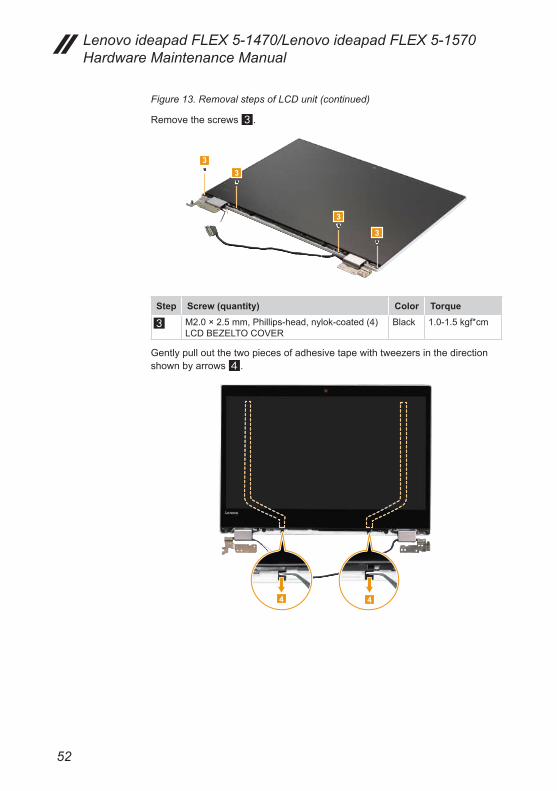
Figure 13. Removal steps of LCD unit (continued)
Remove the screws 3.
3
3
33
Step Screw (quantity) Color Torque
3 M2.0 × 2.5 mm, Phillips-head, nylok-coated (4)LCD BEZELTO COVER
Black 1.0-1.5 kgf*cm
Gently pull out the two pieces of adhesive tape with tweezers in the direction shown by arrows 4.
4 4
53
Lenovo ideapad FLEX 5-1470/Lenovo ideapad FLEX 5-1570
Figure 13. Removal steps of LCD unit (continued)
Lift the LCD unit 5.
5
5

54
Lenovo ideapad FLEX 5-1470/Lenovo ideapad FLEX 5-1570 Hardware Maintenance Manual
1140 Camera board, sensor board and EDP cable
For access, remove these FRUs in order:• “1010 Base cover” on page 31• “1020 Battery pack” on page 33• “1030 Solid state disk” on page 34• “1040 Hard disk drive” on page 35• “1050 PCI Express Mini Card for wireless LAN” on page 36• “1060 Speakers” on page 38• “1080 Fan and Heat Sink assembly” on page 41• “1090 IO board” on page 44• “1100 System board” on page 46• “1110 Upper case” on page 48• “1130 LCD unit” on page 51
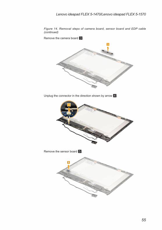
Figure 14. Removal steps of camera board, sensor board and EDP cable
Peel off the tape that secures the camera board 1. Unplug the connector in the direction shown by arrow 2.
1
2
When installing: Make sure that the connector is attached firmly.
55
Lenovo ideapad FLEX 5-1470/Lenovo ideapad FLEX 5-1570
Figure 14. Removal steps of camera board, sensor board and EDP cable (continued)
Remove the camera board 3.
3
Unplug the connector in the direction shown by arrow 4.
4
Remove the sensor board 5.
5
56
Lenovo ideapad FLEX 5-1470/Lenovo ideapad FLEX 5-1570 Hardware Maintenance Manual
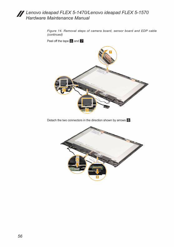
Figure 14. Removal steps of camera board, sensor board and EDP cable (continued)
Peel off the tape 6 and 7.
7
6
6
Detach the two connectors in the direction shown by arrows 8.
8
8
57
Lenovo ideapad FLEX 5-1470/Lenovo ideapad FLEX 5-1570
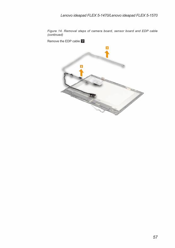
Figure 14. Removal steps of camera board, sensor board and EDP cable (continued)
Remove the EDP cable 9.
9
9

58
Lenovo ideapad FLEX 5-1470/Lenovo ideapad FLEX 5-1570 Hardware Maintenance Manual
1150 LCD hinges
For access, remove these FRUs in order:• “1010 Base cover” on page 31• “1020 Battery pack” on page 33• “1030 Solid state disk” on page 34• “1040 Hard disk drive” on page 35• “1050 PCI Express Mini Card for wireless LAN” on page 36• “1060 Speakers” on page 38• “1080 Fan and Heat Sink assembly” on page 41• “1090 IO board” on page 44• “1100 System board” on page 46• “1110 Upper case” on page 48• “1130 LCD unit” on page 51• “1140 Camera board, sensor board and EDP cable” on page 54
Figure 15. LCD hinges
Remove the screws 1.
1
1
1
1
1
1
Step Screw (quantity) Color Torque
1 M2.5 × 2.5 mm, Phillips-head, nylok-coated (6) HINGE TO LCD COVER
Black 1.5-2.0 kgf*cm

59
Lenovo ideapad FLEX 5-1470/Lenovo ideapad FLEX 5-1570
Figure 15. Removal steps of LCD hinges (continued)
Then release the hinges in the direction shown by arrows 2.
2
2
60
Lenovo ideapad FLEX 5-1470/Lenovo ideapad FLEX 5-1570 Hardware Maintenance Manual
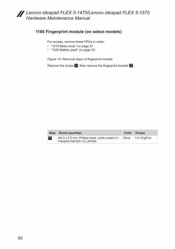
1160 Fingerprint module (on select models)
For access, remove these FRUs in order:• “1010 Base cover” on page 31• “1020 Battery pack” on page 33
Figure 16. Removal steps of fingerprint module
Remove the screw 1, then remove the fingerprint bracket 2.
Step Screw (quantity) Color Torque
1 M2.0 x 2.5 mm, Phillips-head, nylok-coated (1) FINGER PINTER TO UPPER
Silver 1.0-1.5 kgf*cm
61
Lenovo ideapad FLEX 5-1470/Lenovo ideapad FLEX 5-1570
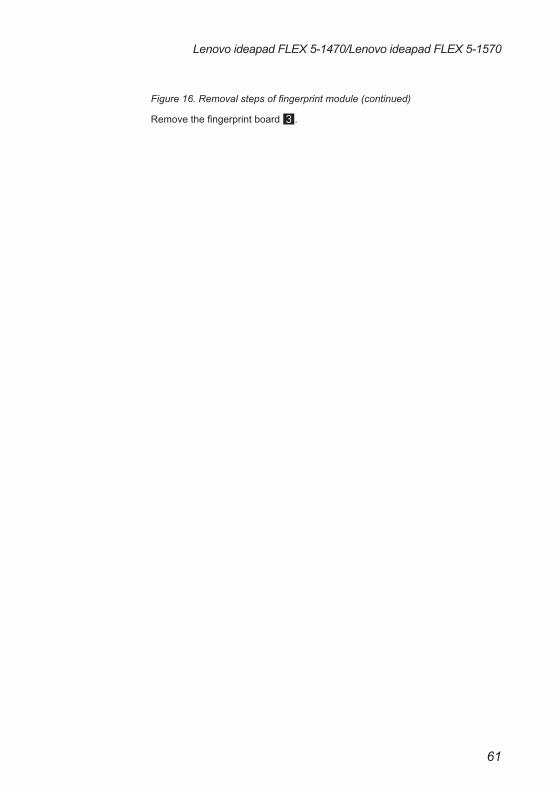
Figure 16. Removal steps of fingerprint module (continued)
Remove the fingerprint board 3.
62
Lenovo ideapad FLEX 5-1470/Lenovo ideapad FLEX 5-1570 Hardware Maintenance Manual
Locations
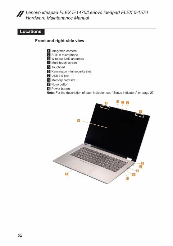
Front and right-side view
a Integrated camerab Built-in microphonec Wireless LAN antennasd Multi-touch screene Touchpadf Kensington mini security slotg USB 3.0 porth Memory card slot9 Novo buttonj Power buttonNote: For the description of each indicator, see “Status indicators” on page 27.
1 223
3
4
58
910
67

63
Lenovo ideapad FLEX 5-1470/Lenovo ideapad FLEX 5-1570
Bottom and left-side view
a Speakersb AC power adapter jackc Battery status indicatorNote: For the description of each indicator, see “Status indicators” on page 27.4 HDMI porte USB 3.0 portf Type-C portg Combo audio jack
1
1
23
45
67
64
Lenovo ideapad FLEX 5-1470/Lenovo ideapad FLEX 5-1570 Hardware Maintenance Manual
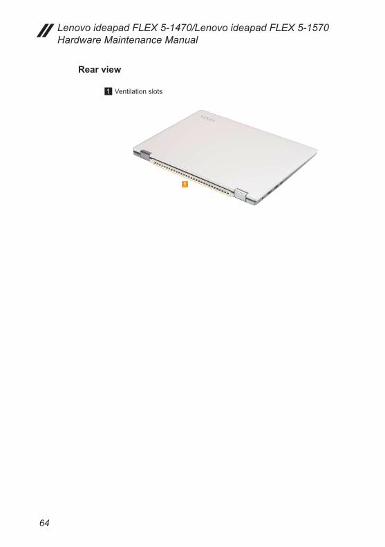
Rear view
a Ventilation slots
1

65
Lenovo ideapad FLEX 5-1470/Lenovo ideapad FLEX 5-1570
Parts listThis section presents the following service parts:• “Overall” on page 66• “LCD FRUs” on page 71• “AC adapters” on page 73• “Screws” on page 73
Notes:• EachFRUisavailableforall typesormodels,unlessspecifictypesormodels
arespecified.
Attention:DonotattempttoreplaceanFRUonyourown.IfanFRUisdamaged,contactaLenovoauthorizedserviceroramarketingrepresentativeforreplacementorrepair.Onlyqualifiedtechnicianscaninspectorrepairthisproduct.
66
Lenovo ideapad FLEX 5-1470/Lenovo ideapad FLEX 5-1570 Hardware Maintenance Manual
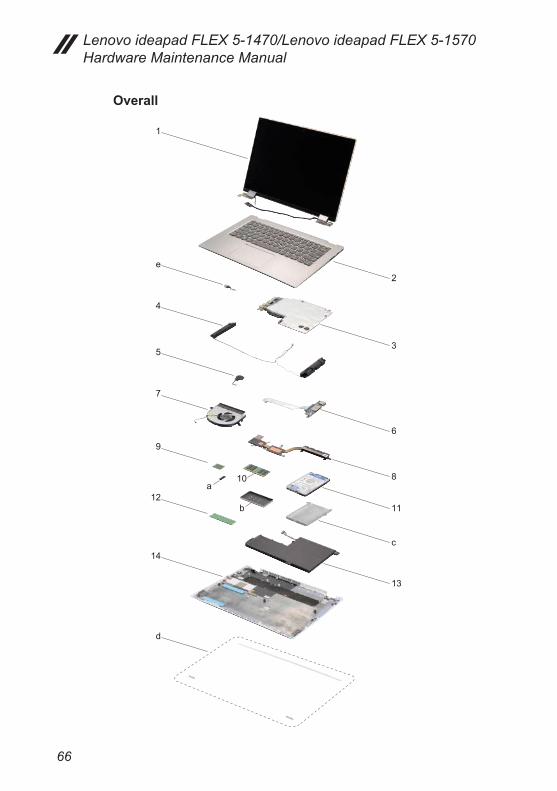
Overall
1
e
4
5
7
9
10a
b12
14
d
2
3
6
8
11
c
13

67
Lenovo ideapad FLEX 5-1470/Lenovo ideapad FLEX 5-1570
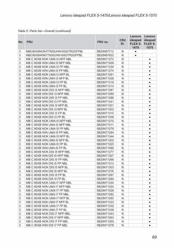
Table 5. Parts list—Overall
No. FRU FRU no. CRU ID.
Lenovo ideapad FLEX 5-
1470
Lenovo ideapad FLEX 5-
1570a-e see “Miscellaneous parts” on page 72.1 LCD unit (see “LCD FRUs” on page 71.)2 Upper Case C 80XALNVOBFPNBLW/KBUS 5CB0N67794 N ●2 Upper Case C 80XA LNVOBFPBLW/KBUS 5CB0N67790 N ●2 Upper Case C 80XALNVOBFPNBLW/KBSP 5CB0N67799 N ●2 Upper Case C 80XA LNVOBFPBLW/KBSP 5CB0N67792 N ●2 Upper CaseC80XALNVOBFPNBLW/KBCF-E 5CB0N67801 N ●2 Upper Case C80XALNVOBFPBLW/KBCF-E 5CB0N67798 N ●2 Upper Case C80XALNVOBNFPNBLW/KBUS 5CB0N67797 N ●2 Upper Case C 80XALNVOBNFPBLW/KBUS 5CB0N67796 N ●2 Upper Case C80XALNVOBNFPNBLW/KBSP 5CB0N67789 N ●2 Upper Case C 80XALNVOBNFPBLW/KBSP 5CB0N67795 N ●2 UpperCaseC80XALNVOBNFPNBLW/KBCF-E 5CB0N67800 N ●2 Upper CaseC80XALNVOBNFPBLW/KBCF-E 5CB0N67793 N ●2 Upper Case C 80XA LNVOBFPBLW/KBUSA 5CB0N89971 N ●2 Upper Case C 80XALNVOBNFPBLW/KBUSA 5CB0N89970 N ●2 Upper Case C80XB FP W/KB NBL US 5CB0N71295 N ●2 Upper Case C80XB FP W/KB BL US 5CB0N71336 N ●2 Upper Case C80XB FPW/KB NBL CF-EN 5CB0N71308 N ●2 Upper Case C80XB FP W/KB BL CF-EN 5CB0N71305 N ●2 Upper Case C80XB FP W/KB NBL SPN 5CB0N71297 N ●2 Upper Case C80XB FP W/KB BL SPN 5CB0N71312 N ●2 Upper Case C80XB FP W/KB BL USA 5CB0N71262 N ●2 Upper Case C80XB NFP W/KB NBL US 5CB0N71317 N ●2 Upper Case C80XB NFP W/KB BL US 5CB0N71281 N ●2 Upper Case C80XB NFPW/KB NBLCF-EN 5CB0N71324 N ●2 Upper Case C80XB NFP W/KB BLCF-EN 5CB0N71284 N ●2 Upper Case C80XB NFP W/KB NBL SPN 5CB0N71296 N ●2 Upper Case C80XB NFP W/KB BL SPN 5CB0N71342 N ●2 Upper Case C80XB NFP W/KB BL USA 5CB0N71315 N ●3 MB C 80X8 NOK 4415U UMA NFPNBL 5B20N67507 N ●3 MB C 80X8 WIN 4415U UMA NFPNBL 5B20N67710 N ●3 MB C 80X8 NOK 4415U UMA FP NBL 5B20N67733 N ●3 MB C 80X8 WIN 4415U UMA FP NBL 5B20N67753 N ●3 MB C 80X8 NOK 4415U UMA NFP BL 5B20N67548 N ●3 MB C 80X8 WIN 4415U UMA NFP BL 5B20N67453 N ●3 MB C 80X8 NOK 4415U UMA FP BL 5B20N67610 N ●3 MB C 80X8 WIN 4415U UMA FP BL 5B20N67489 N ●3 MBC80X8NOK4415UN16SGTR2GNFPNBL 5B20N67561 N ●3 MBC80X8WIN4415UN16SGTR2GNFPNBL 5B20N67697 N ●3 MB C80X8NOK4415UN16SGTR2GFPNBL 5B20N67582 N ●3 MB C80X8WIN4415UN16SGTR2GFPNBL 5B20N67413 N ●3 MB C80X8NOK4415UN16SGTR2GNFPBL 5B20N67731 N ●3 MB C80X8WIN4415UN16SGTR2GNFPBL 5B20N67668 N ●3 MB C 80X8NOK4415UN16SGTR2GFPBL 5B20N67627 N ●3 MB C 80X8WIN4415UN16SGTR2GFPBL 5B20N67369 N ●

68
Lenovo ideapad FLEX 5-1470/Lenovo ideapad FLEX 5-1570 Hardware Maintenance Manual
Table 5. Parts list—Overall (continued)
No. FRU FRU no. CRU ID.
Lenovo ideapad FLEX 5-
1470
Lenovo ideapad FLEX 5-
15703 MB C 80X8 NOKI37100UHUMANFPNBL 5B20N67702 N ●3 MB C 80X8 WINI37100UHUMANFPNBL 5B20N67680 N ●3 MB C 80X8 NOK I37100UHUMAFPNBL 5B20N67353 N ●3 MB C 80X8 WIN I37100UHUMAFPNBL 5B20N67428 N ●3 MB C 80X8 NOK I37100UHUMANFPBL 5B20N67782 N ●3 MB C 80X8 WIN I37100UHUMANFPBL 5B20N67758 N ●3 MB C 80X8 NOK I37100UH UMAFPBL 5B20N67491 N ●3 MB C 80X8 WIN I37100UH UMAFPBL 5B20N67384 N ●3 MBC80X8NOKI37100UHN16SGTRNFPNBL 5B20N67338 N ●3 MBC80X8WINI37100UHN16SGTRNFPNBL 5B20N67656 N ●3 MBC80X8NOKI37100UHN16SGTRFPNBL 5B20N67705 N ●3 MBC80X8WINI37100UHN16SGTRFPNBL 5B20N67771 N ●3 MBC80X8NOKI37100UHN16SGTRNFPBL 5B20N67385 N ●3 MBC80X8WINI37100UHN16SGTRNFPBL 5B20N67399 N ●3 MBC80X8NOKI37100UHN16SGTR2GFPBL 5B20N67390 N ●3 MBC80X8WINI37100UHN16SGTR2GFPBL 5B20N67776 N ●3 MB C 80X8 NOKI57200UHUMANFPNBL 5B20N67484 N ●3 MB C 80X8 WINI57200UHUMANFPNBL 5B20N67560 N ●3 MB C 80X8 NOK I57200UHUMAFPNBL 5B20N67769 N ●3 MB C 80X8 WIN I57200UHUMAFPNBL 5B20N67747 N ●3 MB C 80X8 NOK I57200UHUMANFPBL 5B20N67678 N ●3 MB C 80X8 WIN I57200UHUMANFPBL 5B20N67638 N ●3 MB C 80X8 NOK I57200UH UMAFPBL 5B20N67317 N ●3 MB C 80X8 WIN I57200UH UMAFPBL 5B20N67526 N ●3 MBC80X8NOKI57200UHN16SGTRNFPNBL 5B20N67471 N ●3 MBC80X8WINI57200UHN16SGTRNFPNBL 5B20N67358 N ●3 MBC80X8NOKI57200UHN16SGTRFPNBL 5B20N67590 N ●3 MBC80X8WINI57200UHN16SGTRFPNBL 5B20N67368 N ●3 MBC80X8NOKI57200UHN16SGTRNFPBL 5B20N67573 N ●3 MBC80X8WINI57200UHN16SGTRNFPBL 5B20N67566 N ●3 MBC80X8NOKI57200UHN16SGTR2GFPBL 5B20N67434 N ●3 MBC80X8WINI57200UHN16SGTR2GFPBL 5B20N67503 N ●3 MB C 80X8 NOKI77500UHUMANFPNBL 5B20N67578 N ●3 MB C 80X8 WINI77500UHUMANFPNBL 5B20N67462 N ●3 MB C 80X8 NOK I77500UHUMAFPNBL 5B20N67565 N ●3 MB C 80X8 WIN I77500UHUMAFPNBL 5B20N67410 N ●3 MB C 80X8 NOK I77500UHUMANFPBL 5B20N67666 N ●3 MB C 80X8 WIN I77500UHUMANFPBL 5B20N67325 N ●3 MB C 80X8 NOK I77500UH UMAFPBL 5B20N67518 N ●3 MB C 80X8 WIN I77500UH UMAFPBL 5B20N67700 N ●3 MBC80X8NOKI77500UHN16SGTRNFPNBL 5B20N67667 N ●3 MBC80X8WINI77500UHN16SGTRNFPNBL 5B20N67766 N ●3 MBC80X8NOKI77500UHN16SGTRFPNBL 5B20N67739 N ●3 MBC80X8WINI77500UHN16SGTRFPNBL 5B20N67361 N ●3 MBC80X8NOKI77500UHN16SGTRNFPBL 5B20N67429 N ●3 MBC80X8WINI77500UHN16SGTRNFPBL 5B20N67321 N ●
69
Lenovo ideapad FLEX 5-1470/Lenovo ideapad FLEX 5-1570
No. FRU FRU no. CRU ID.
Lenovo ideapad FLEX 5-
1470
Lenovo ideapad FLEX 5-
15703 MBC80X8NOKI77500UHN16SGTR2GFPBL 5B20N67712 N ●3 MBC80X8WINI77500UHN16SGTR2GFPBL 5B20N67622 N ●3 MB C 80XB NOK UMA I3 NFP NBL 5B20N71272 N ●3 MB C 80XB WIN UMA I3 NFP NBL 5B20N71309 N ●3 MB C 80XB NOK UMA I3 FP NBL 5B20N71339 N ●3 MB C 80XB WIN UMA I3 FP NBL 5B20N71274 N ●3 MB C 80XB NOK UMA I3 NFP BL 5B20N71291 N ●3 MB C 80XB WIN UMA I3 NFP BL 5B20N71328 N ●3 MB C 80XB NOK UMA I3 FP BL 5B20N71319 N ●3 MB C 80XB WIN UMA I3 FP BL 5B20N71314 N ●3 MB C 80XB NOK DIS I3 NFP NBL 5B20N71287 N ●3 MB C 80XB WIN DIS I3 NFP NBL 5B20N71269 N ●3 MB C 80XB NOK DIS I3 FP NBL 5B20N71288 N ●3 MB C 80XB WIN DIS I3 FP NBL 5B20N71341 N ●3 MB C 80XB NOK DIS I3 NFP BL 5B20N71301 N ●3 MB C 80XB WIN DIS I3 NFP BL 5B20N71322 N ●3 MB C 80XB NOK DIS I3 FP BL 5B20N71310 N ●3 MB C 80XB WIN DIS I3 FP BL 5B20N71306 N ●3 MB C 80XB NOK UMA I5 NFP NBL 5B20N71270 N ●3 MB C 80XB WIN UMA I5 NFP NBL 5B20N71311 N ●3 MB C 80XB NOK UMA I5 FP NBL 5B20N71279 N ●3 MB C 80XB WIN UMA I5 FP NBL 5B20N71264 N ●3 MB C 80XB NOK UMA I5 NFP BL 5B20N71344 N ●3 MB C 80XB WIN UMA I5 NFP BL 5B20N71302 N ●3 MB C 80XB NOK UMA I5 FP BL 5B20N71325 N ●3 MB C 80XB WIN UMA I5 FP BL 5B20N71286 N ●3 MB C 80XB NOK DIS I5 NFP NBL 5B20N71277 N ●3 MB C 80XB WIN DIS I5 NFP NBL 5B20N71327 N ●3 MB C 80XB NOK DIS I5 FP NBL 5B20N71266 N ●3 MB C 80XB WIN DIS I5 FP NBL 5B20N71313 N ●3 MB C 80XB NOK DIS I5 NFP BL 5B20N71303 N ●3 MB C 80XB WIN DIS I5 NFP BL 5B20N71276 N ●3 MB C 80XB NOK DIS I5 FP BL 5B20N71267 N ●3 MB C 80XB WIN DIS I5 FP BL 5B20N71285 N ●3 MB C 80XB NOK UMA I7 NFP NBL 5B20N71334 N ●3 MB C 80XB WIN UMA I7 NFP NBL 5B20N71320 N ●3 MB C 80XB NOK UMA I7 FP NBL 5B20N71326 N ●3 MB C 80XB WIN UMA I7 FP NBL 5B20N71282 N ●3 MB C 80XB NOK UMA I7 NFP BL 5B20N71292 N ●3 MB C 80XB WIN UMA I7 NFP BL 5B20N71333 N ●3 MB C 80XB NOK UMA I7 FP BL 5B20N71332 N ●3 MB C 80XB WIN UMA I7 FP BL 5B20N71338 N ●3 MB C 80XB NOK DIS I7 NFP NBL 5B20N71343 N ●3 MB C 80XB WIN DIS I7 NFP NBL 5B20N71263 N ●3 MB C 80XB NOK DIS I7 FP NBL 5B20N71265 N ●3 MB C 80XB WIN DIS I7 FP NBL 5B20N71278 N ●
Table 5. Parts list—Overall (continued)
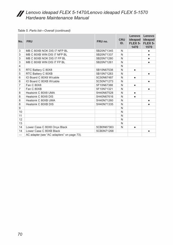
70
Lenovo ideapad FLEX 5-1470/Lenovo ideapad FLEX 5-1570 Hardware Maintenance Manual
No. FRU FRU no. CRU ID.
Lenovo ideapad FLEX 5-
1470
Lenovo ideapad FLEX 5-
15703 MB C 80XB NOK DIS I7 NFP BL 5B20N71345 N ●3 MB C 80XB WIN DIS I7 NFP BL 5B20N71337 N ●3 MB C 80XB NOK DIS I7 FP BL 5B20N71280 N ●3 MB C 80XB WIN DIS I7 FP BL 5B20N71261 N ●4 N5 RTC Battery C 80X8 5B10N67538 N ●5 RTC Battery C 80XB 5B10N71283 N ●6 IO Board C 80X8 W/cable 5C50N67487 N ●6 IO Board C 80XB W/cable 5C50N71273 N ●7 Fan C 80X8 5F10N67388 N ●7 Fan C 80XB 5F10N71321 N ●8 Heatsink C 80X8 UMA 5H40N67528 N ●8 Heatsink C 80X8 DIS 5H40N67616 N ●8 Heatsink C 80XB UMA 5H40N71260 N ●8 Heatsink C 80XB DIS 5H40N71335 N ●9 N10 N11 N12 N13 N14 Lower Case C 80X8 Onyx Black 5CB0N67363 N ●14 Lower Case C 80XB Black 5CB0N71268 ●— AC adapter (see “AC adapters” on page 73).
Table 5. Parts list—Overall (continued)
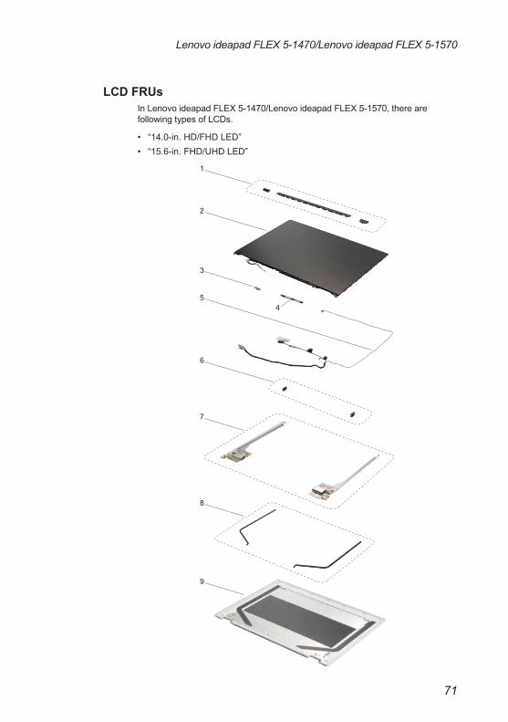
71
Lenovo ideapad FLEX 5-1470/Lenovo ideapad FLEX 5-1570
LCD FRUsIn Lenovo ideapad FLEX 5-1470/Lenovo ideapad FLEX 5-1570, there are following types of LCDs.
• “14.0-in. HD/FHD LED”• “15.6-in. FHD/UHD LED”
1
2
3
6
7
8
9
45
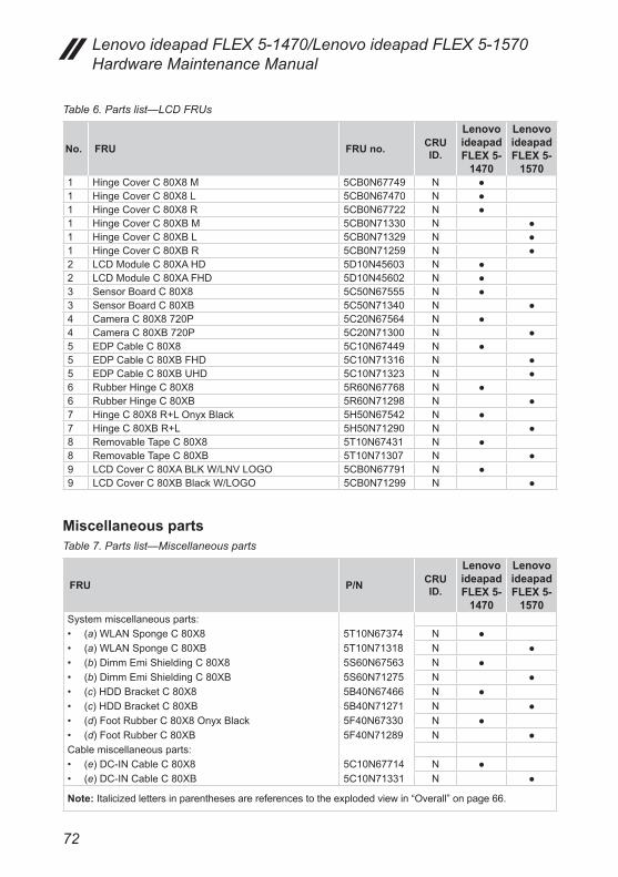
72
Lenovo ideapad FLEX 5-1470/Lenovo ideapad FLEX 5-1570 Hardware Maintenance Manual
Table 6. Parts list—LCD FRUs
No. FRU FRU no. CRU ID.
Lenovo ideapad FLEX 5-
1470
Lenovo ideapad FLEX 5-
15701 Hinge Cover C 80X8 M 5CB0N67749 N ●1 Hinge Cover C 80X8 L 5CB0N67470 N ●1 Hinge Cover C 80X8 R 5CB0N67722 N ●1 Hinge Cover C 80XB M 5CB0N71330 N ●1 Hinge Cover C 80XB L 5CB0N71329 N ●1 Hinge Cover C 80XB R 5CB0N71259 N ●2 LCD Module C 80XA HD 5D10N45603 N ●2 LCD Module C 80XA FHD 5D10N45602 N ●3 Sensor Board C 80X8 5C50N67555 N ●3 Sensor Board C 80XB 5C50N71340 N ●4 Camera C 80X8 720P 5C20N67564 N ●4 Camera C 80XB 720P 5C20N71300 N ●5 EDP Cable C 80X8 5C10N67449 N ●5 EDP Cable C 80XB FHD 5C10N71316 N ●5 EDP Cable C 80XB UHD 5C10N71323 N ●6 Rubber Hinge C 80X8 5R60N67768 N ●6 Rubber Hinge C 80XB 5R60N71298 N ●7 Hinge C 80X8 R+L Onyx Black 5H50N67542 N ●7 Hinge C 80XB R+L 5H50N71290 N ●8 Removable Tape C 80X8 5T10N67431 N ●8 Removable Tape C 80XB 5T10N71307 N ●9 LCD Cover C 80XA BLK W/LNV LOGO 5CB0N67791 N ●9 LCD Cover C 80XB Black W/LOGO 5CB0N71299 N ●
Miscellaneous partsTable 7. Parts list—Miscellaneous parts
FRU P/N CRU ID.
Lenovo ideapad FLEX 5-
1470
Lenovo ideapad FLEX 5-
1570System miscellaneous parts:• (a) WLAN Sponge C 80X8 5T10N67374 N ●• (a) WLAN Sponge C 80XB 5T10N71318 N ●• (b) Dimm Emi Shielding C 80X8 5S60N67563 N ●• (b) Dimm Emi Shielding C 80XB 5S60N71275 N ●• (c) HDD Bracket C 80X8 5B40N67466 N ●• (c) HDD Bracket C 80XB 5B40N71271 N ●• (d) Foot Rubber C 80X8 Onyx Black 5F40N67330 N ●• (d) Foot Rubber C 80XB 5F40N71289 N ●Cable miscellaneous parts:• (e) DC-IN Cable C 80X8 5C10N67714 N ●• (e) DC-IN Cable C 80XB 5C10N71331 N ●
Note: Italicized letters in parentheses are references to the exploded view in “Overall” on page 66.

73
Lenovo ideapad FLEX 5-1470/Lenovo ideapad FLEX 5-1570
AC adaptersTable 8. Parts list—AC adapters
FRU P/N CRU ID.
Lenovo ideapad FLEX 5-
1470
Lenovo ideapad FLEX 5-
1570*
ScrewsTable 9. Parts list—Screws
FRU P/N CRU ID.
Lenovo ideapad FLEX 5-
1470
Lenovo ideapad FLEX 5-
1570Screw Pack C 80X8 5S10N67498 N ●Screw Pack C 80XB 5S10N71293 N ●

74
Lenovo ideapad FLEX 5-1470/Lenovo ideapad FLEX 5-1570 Hardware Maintenance Manual
Power cordsA Lenovo power cord for a specific country or region is usually available only in that country or region: Table 10. Parts list—3-pin power cords
Region P/N CRU ID.
• *

75
Lenovo ideapad FLEX 5-1470/Lenovo ideapad FLEX 5-1570
Region P/N CRU ID.
Table 10. Parts list—3-pin power cords (continued)

76
Lenovo ideapad FLEX 5-1470/Lenovo ideapad FLEX 5-1570 Hardware Maintenance Manual
Region P/N CRU ID.
Table 10. Parts list—3-pin power cords (continued)

77
Notices
Notices
Lenovo may not offer the products, services, or features discussed in this document in all countries. Consult your local Lenovo representative for information on the products and services currently available in your area. Any reference to a Lenovo product, program, or service is not intended to state or imply that only that Lenovo product, program, or service may be used. Any functionally equivalent product, program, or service that does not infringe any Lenovo intellectual property right may be used instead. However, it is the user’s responsibility to evaluate and verify the operation of any other product, program, or service.Lenovo may have patents or pending patent applications covering subject matter described in this document. The furnishing of this document does not give you any license to these patents.
LENOVO GROUP LTD. PROVIDES THIS PUBLICATION “AS IS” WITHOUT WARRANTY OF ANY KIND, EITHER EXPRESS OR IMPLIED, INCLUDING, BUT NOT LIMITED TO, THE IMPLIED WARRANTIES OF NON-INFRINGEMENT, MERCHANTABILITY OR FITNESS FOR A PARTICULAR PURPOSE. Some jurisdictions do not allow disclaimer of express or implied warranties in certain transactions, therefore, this statement may not apply to you.This information could include technical inaccuracies or typographical errors. Changes are periodically made to the information herein; these changes will be incorporated in new editions of the publication. Lenovo may make improvements and/or changes in the product(s) and/or the program(s) described in this publication at any time without notice.The products described in this document are not intended for use in implantation or other life support applications where malfunction may result in injury or death to persons. The information contained in this document does not affect or change Lenovo product specifications or warranties. Nothing in this document shall operate as an express or implied license or indemnity under the intellectual property rights of Lenovo or third parties. All information contained in this document was obtained in specific environments and is presented as an illustration. The result obtained in other operating environments may vary.Lenovo may use or distribute any of the information you supply in any way it believes appropriate without incurring any obligation to you. Any references in this publication to non-Lenovo Web sites are provided for convenience only and do not in any manner serve as an endorsement of those Web sites. The materials at those Web sites are not part of the materials for this Lenovo product, and use of those Web sites is at your own risk. Any performance data contained herein was determined in a controlled environment. Therefore, the result obtained in other operating environments may vary significantly. Some measurements may have been made on development-level systems and there is no guarantee that these measurements will be the same on generally available systems. Furthermore, some measurements may have been estimated through extrapolation. Actual results may vary. Users of this document should verify the applicable data for their specific environment.

78
Lenovo ideapad FLEX 5-1470/Lenovo ideapad FLEX 5-1570 Hardware Maintenance Manual
TrademarksThe following terms are either registered trademarks or trademarks of Lenovo in the United States and/or other countries:
Lenovo®
Lenovo logo®
OneKey
The following term is trademark of Microsoft Corporation in the United States, other countries, or both:
Windows®
The following term is trademark of Intel Corporation or its subsidiaries in the United States, other countries, or both:
Intel®
Other company, product, or service names may be the trademarks or service marks of others.