
FLENDER Gear Units - Siemens · FLENDER Gear Units Gear unit 5011en ... 9 Service & Support ......
190
siemens.com FLENDER Gear Units Gear unit 5011en Operating Instructions Edition 03/2016 H..V, B..V 1...22
Transcript of FLENDER Gear Units - Siemens · FLENDER Gear Units Gear unit 5011en ... 9 Service & Support ......
siemens.com
FLENDER Gear UnitsGear unit5011en
Operating Instructions
Edition 03/2016
H..V, B..V 1...22

05.10.2016 00:16V2.00
Gear unit
FLENDER Gear Units5011en
Operating Instructions
H..V, B..V 1...22
Edition 03/2016
Introduction 1
Safety instructions 2
Description 3
Application planning 4
Assembly 5
Commissioning 6
Operation 7
Servicing 8
Service & Support 9
Disposal 10
Spare parts 11
Quality documents A
Technical data B

Legal informationWarning notice system
This manual contains notices you have to observe in order to ensure your personal safety, as well as to prevent damage to property. The notices referring to your personal safety are highlighted in the manual by a safety alert symbol, notices referring only to property damage have no safety alert symbol. These notices shown below are graded according to the degree of danger.
DANGERindicates that death or severe personal injury will result if proper precautions are not taken.
WARNINGindicates that death or severe personal injury may result if proper precautions are not taken.
CAUTIONindicates that minor personal injury can result if proper precautions are not taken.
NOTICEindicates that property damage can result if proper precautions are not taken.If more than one degree of danger is present, the warning notice representing the highest degree of danger will be used. A notice warning of injury to persons with a safety alert symbol may also include a warning relating to property damage.
Qualified PersonnelThe product/system described in this documentation may be operated only by personnel qualified for the specific task in accordance with the relevant documentation, in particular its warning notices and safety instructions. Qualified personnel are those who, based on their training and experience, are capable of identifying risks and avoiding potential hazards when working with these products/systems.
Proper use of Siemens productsNote the following:
WARNINGSiemens products may only be used for the applications described in the catalog and in the relevant technical documentation. If products and components from other manufacturers are used, these must be recommended or approved by Siemens. Proper transport, storage, installation, assembly, commissioning, operation and maintenance are required to ensure that the products operate safely and without any problems. The permissible ambient conditions must be complied with. The information in the relevant documentation must be observed.
TrademarksAll names identified by ® are registered trademarks of Siemens AG. The remaining trademarks in this publication may be trademarks whose use by third parties for their own purposes could violate the rights of the owner.
Disclaimer of LiabilityWe have reviewed the contents of this publication to ensure consistency with the hardware and software described. Since variance cannot be precluded entirely, we cannot guarantee full consistency. However, the information in this publication is reviewed regularly and any necessary corrections are included in subsequent editions.
Siemens AGProcess Industries and DrivesPostfach 48 4890026 NÜRNBERGGERMANY
Document order number: Ⓟ 10/2016 Subject to change
Copyright © Siemens AG 2016.All rights reserved

Table of contents
1 Introduction.................................................................................................................................................13
1.1 General information................................................................................................................13
1.2 Lubricants...............................................................................................................................14
2 Safety instructions......................................................................................................................................15
2.1 Security notes........................................................................................................................15
2.2 The five safety rules...............................................................................................................15
2.3 General information................................................................................................................15
2.4 General warnings and symbols..............................................................................................17
2.5 Special types of danger and personal protective equipment.................................................18
2.6 Intended use..........................................................................................................................20
3 Description..................................................................................................................................................23
3.1 General description................................................................................................................23
3.2 Output shaft versions.............................................................................................................24
3.3 Housing..................................................................................................................................253.3.1 Aerator gear unit....................................................................................................................303.3.2 Agitator gear unit....................................................................................................................313.3.3 Water turbine gear unit...........................................................................................................333.3.4 Pulper gear unit......................................................................................................................34
3.4 Oil supply to the gear unit......................................................................................................363.4.1 Splash lubrication...................................................................................................................363.4.2 Pressure lubrication...............................................................................................................363.4.2.1 Pump......................................................................................................................................403.4.2.2 Oil filter...................................................................................................................................40
3.5 Bearing arrangement of the shafts.........................................................................................40
3.6 Shaft seal...............................................................................................................................403.6.1 Rotary shaft sealing rings.......................................................................................................413.6.2 Labyrinth seals.......................................................................................................................413.6.3 Taconite seal..........................................................................................................................423.6.4 Centrifugal disk......................................................................................................................443.6.5 Oil retaining pipe....................................................................................................................45
3.7 Backstop................................................................................................................................46
3.8 Cooling...................................................................................................................................473.8.1 Fan.........................................................................................................................................473.8.2 Cooling coil.............................................................................................................................483.8.3 Mounted oil supply system.....................................................................................................513.8.3.1 Mounted oil supply system with air-oil cooler.........................................................................513.8.3.2 Mounted oil supply system with water-oil cooler....................................................................53
Gear unit 5011enOperating Instructions 03/2016 5

3.8.3.3 Pump......................................................................................................................................553.8.3.4 Oil filter...................................................................................................................................553.8.4 Separate oil supply system....................................................................................................55
3.9 Couplings...............................................................................................................................56
3.10 Shrink disk..............................................................................................................................56
3.11 Heating...................................................................................................................................57
3.12 Oil level indicator....................................................................................................................59
3.13 Oil level monitoring system....................................................................................................59
3.14 Oil temperature monitoring.....................................................................................................60
3.15 Bearing monitoring.................................................................................................................613.15.1 Bearing monitoring using a Pt 100 resistance thermometer..................................................613.15.2 Bearing monitoring by shock-pulse transducer......................................................................613.15.3 Bearing monitoring by acceleration sensor............................................................................62
3.16 Speed encoder.......................................................................................................................63
3.17 Auxiliary drive.........................................................................................................................643.17.1 Overrunning clutch.................................................................................................................67
4 Application planning...................................................................................................................................69
4.1 Scope of delivery....................................................................................................................69
4.2 Transport................................................................................................................................69
4.3 Attachment points..................................................................................................................71
4.4 Special aspects of gear unit lubrication and preservation......................................................744.4.1 Regreasing rolling-contact bearings.......................................................................................744.4.1.1 Grease-lubricated rolling-contact bearing..............................................................................744.4.1.2 Grease-lubricated rolling-contact bearing in oil retaining pipe...............................................744.4.2 Oil filling and oil drain.............................................................................................................764.4.3 Special aspects of gear unit preservation..............................................................................77
5 Assembly....................................................................................................................................................79
5.1 General assembly instructions...............................................................................................79
5.2 Unpacking the gear unit.........................................................................................................80
5.3 Gear unit assembly................................................................................................................815.3.1 Foundation.............................................................................................................................815.3.2 Description of assembly work................................................................................................825.3.2.1 Alignment...............................................................................................................................845.3.3 Gear unit assembly on housing foot.......................................................................................865.3.3.1 Installation on a foundation frame..........................................................................................865.3.3.2 Mounting on a concrete foundation using stone bolts or foundation blocks...........................875.3.3.3 Mounting on a concrete foundation using anchor bolts..........................................................895.3.4 Mounting on a mounting flange or block flange.....................................................................915.3.4.1 Mating flange on the machine side........................................................................................915.3.4.2 Assembly................................................................................................................................925.3.4.3 Dismantling............................................................................................................................955.3.5 Mounting the coupling flange on the output side on type H.BV and B.BV gear units............965.3.5.1 Requirements.........................................................................................................................96
Table of contents
Gear unit 5011en6 Operating Instructions 03/2016

5.3.5.2 Installing the gear unit............................................................................................................965.3.6 Mounting the torque arm for the gear unit housing................................................................975.3.6.1 Mounting the torque arm........................................................................................................975.3.6.2 Mounting the torque arm........................................................................................................97
5.4 Shaft-mounted gear unit with hollow shaft.............................................................................995.4.1 Shaft-mounted gear unit with hollow shaft and parallel keyway.............................................995.4.1.1 Preparations...........................................................................................................................995.4.1.2 Assembly..............................................................................................................................1005.4.1.3 Dismantling..........................................................................................................................1025.4.2 Shaft-mounted gear unit with hollow shaft and spline according to DIN 5480.....................1065.4.2.1 Preparations.........................................................................................................................1065.4.2.2 Assembly..............................................................................................................................1075.4.2.3 Dismantling..........................................................................................................................1105.4.3 Shaft-mounted gear unit with hollow shaft and shrink disk..................................................1135.4.3.1 Assembly..............................................................................................................................1135.4.3.2 Dismantling..........................................................................................................................117
5.5 Gear unit with type F flange shaft........................................................................................1175.5.1 Requirements.......................................................................................................................1175.5.2 Installing the gear unit..........................................................................................................117
5.6 Couplings.............................................................................................................................118
5.7 Connecting components......................................................................................................1205.7.1 Gear units with mounted components..................................................................................1205.7.2 Making terminal box connections for pre-wired gear units...................................................1215.7.3 Connecting the cooling coil..................................................................................................1215.7.4 Connecting the air‐oil cooler................................................................................................1225.7.5 Connecting the water-oil cooler............................................................................................1225.7.6 Connecting the heating element..........................................................................................1235.7.7 Connecting the pressure monitor.........................................................................................1245.7.8 Installing a separate oil supply system.................................................................................1245.7.9 Connecting the oil-level monitoring system..........................................................................1245.7.10 Connecting the Pt 100 resistance thermometer...................................................................1255.7.11 Connecting the temperature monitor....................................................................................1255.7.12 Connecting the bearing monitoring system..........................................................................1265.7.13 Connecting a speed encoder...............................................................................................1265.7.14 Connecting the motor pump.................................................................................................1265.7.15 Electrical connections..........................................................................................................127
5.8 Tightening procedure...........................................................................................................1275.8.1 Introduction..........................................................................................................................1275.8.2 Bolt connection classes........................................................................................................1285.8.3 Tightening torques and preload forces.................................................................................129
5.9 Final work.............................................................................................................................130
6 Commissioning.........................................................................................................................................133
6.1 Measures prior to commissioning........................................................................................1336.1.1 Gear unit with backstop........................................................................................................1346.1.2 Gear unit with auxiliary drive................................................................................................1346.1.3 Oil level monitoring system..................................................................................................1356.1.4 Gear units with cooling coil..................................................................................................1356.1.5 Gear unit with heating..........................................................................................................136
Table of contents
Gear unit 5011enOperating Instructions 03/2016 7

6.1.6 Gear unit with oil supply system...........................................................................................1366.1.7 Filling lubricant into gear units with mounted backstop or auxiliary drive.............................137
6.2 Measures during commissioning..........................................................................................137
7 Operation..................................................................................................................................................139
7.1 Operating data.....................................................................................................................139
7.2 Irregularities in operation......................................................................................................139
7.3 Taking the unit out of service...............................................................................................140
8 Servicing...................................................................................................................................................141
8.1 General maintenance information........................................................................................141
8.2 Maintenance schedule.........................................................................................................142
8.3 Maintenance and servicing work..........................................................................................1438.3.1 Checking the oil temperature...............................................................................................1438.3.2 Filling the backstop with oil..................................................................................................1448.3.3 Filling the overrunning clutch of the auxiliary drive with oil..................................................1448.3.4 Checking the auxiliary drive.................................................................................................1458.3.5 Repacking grease in the oil retaining pipe...........................................................................1458.3.6 Cleaning the fan and gear unit.............................................................................................1468.3.7 Checking the cooling coil.....................................................................................................1468.3.8 Inspecting the shrink disk.....................................................................................................1478.3.9 Cleaning the coarse filter.....................................................................................................1488.3.10 Cleaning the double change-over filter................................................................................1488.3.11 Checking the speed monitoring of the auxiliary drive...........................................................1488.3.12 Measuring the vibration levels of the rolling-contact bearings.............................................1498.3.13 Measuring the temperature at the rolling-contact bearings..................................................1498.3.14 Check that all of the fastening bolts are tight.......................................................................1508.3.15 General inspection of the gear unit......................................................................................1508.3.16 Final work.............................................................................................................................150
8.4 Possible faults......................................................................................................................150
9 Service & Support.....................................................................................................................................155
10 Disposal....................................................................................................................................................157
11 Spare parts...............................................................................................................................................159
A Quality documents....................................................................................................................................161
A.1 Declaration of Incorporation.................................................................................................161
B Technical data..........................................................................................................................................163
B.1 General technical data.........................................................................................................163
B.2 Ambient temperature............................................................................................................165
B.3 Types...................................................................................................................................165
B.4 Weights................................................................................................................................168
B.5 Oil quantities........................................................................................................................170
B.6 Enveloping surface sound pressure level............................................................................173
Table of contents
Gear unit 5011en8 Operating Instructions 03/2016

Glossary...................................................................................................................................................183
Index.........................................................................................................................................................185
Tables
Table 2-1 Symbols and markings................................................................................................................16Table 2-2 General warnings........................................................................................................................17Table 3-1 Designs and associated directions of rotation.............................................................................23Table 3-2 Taconite seal versions.................................................................................................................44Table 3-3 Required cooling water flow rate.................................................................................................50Table 3-4 Information about the specific heat output..................................................................................57Table 4-1 Grease quantities for the lower output shaft bearing if taken out of service for > 36 months:......75Table 5-1 Tightening torques at the flange connections..............................................................................97Table 5-2 Motor assignment for housing support .......................................................................................98Table 5-3 Dimensions for the threaded holes at the face sides of gear unit hollow shafts.......................105Table 5-4 Maximum forcing pressures......................................................................................................106Table 5-5 Maximum forcing pressures......................................................................................................113Table 5-6 Tightening torques at the flange connections............................................................................118Table 5-7 Information on tightening fastening bolts...................................................................................128Table 5-8 Preload forces and tightening torques.......................................................................................129Table 7-1 Operating data...........................................................................................................................139Table 8-1 Maintenance and servicing work...............................................................................................142Table 8-2 Possible faults and their rectification.........................................................................................151Table B-1 Weights.....................................................................................................................................168Table B-2 Weights.....................................................................................................................................169Table B-3 Weights.....................................................................................................................................169Table B-4 Weights.....................................................................................................................................169Table B-5 Weights.....................................................................................................................................170Table B-6 Weights.....................................................................................................................................170Table B-7 Weights.....................................................................................................................................170Table B-8 Oil quantities..............................................................................................................................171Table B-9 Oil quantities..............................................................................................................................171Table B-10 Oil quantities..............................................................................................................................171Table B-11 Oil quantities..............................................................................................................................172Table B-12 Oil quantities..............................................................................................................................172Table B-13 Oil quantities..............................................................................................................................172Table B-14 Oil quantities..............................................................................................................................173Table B-15 Oil quantities..............................................................................................................................173Table B-16 Enveloping surface sound pressure level..................................................................................174
Table of contents
Gear unit 5011enOperating Instructions 03/2016 9

Table B-17 Enveloping surface sound pressure level..................................................................................175Table B-18 Enveloping surface sound pressure level..................................................................................176Table B-19 Enveloping surface sound pressure level..................................................................................177Table B-20 Enveloping surface sound pressure level..................................................................................178Table B-21 Enveloping surface sound pressure level..................................................................................179Table B-22 Enveloping surface sound pressure level..................................................................................179Table B-23 Enveloping surface sound pressure level..................................................................................180
Figures
Figure 3-1 Output shaft versions..................................................................................................................25Figure 3-2 Output shaft versions for agitator gear units...............................................................................25Figure 3-3 Sign: Lubrication point.................................................................................................................26Figure 3-4 Gear unit equipment on type H..V gear units with oil expansion unit..........................................27Figure 3-5 Gear unit equipment on type B..V gear units with oil expansion unit..........................................28Figure 3-6 Gear unit equipment on gear units of type H..V with mounted oil supply system.......................29Figure 3-7 Gear unit equipment on type B..V gear units with mounted oil supply system...........................29Figure 3-8 Aerator gear unit, type H.BV.......................................................................................................30Figure 3-9 Aerator gear unit, type B.BV........................................................................................................31Figure 3-10 Type H..V agitator gear unit with oil expansion unit....................................................................32Figure 3-11 Type H..V agitator gear unit with mounted oil supply system......................................................32Figure 3-12 Type H2WV water turbine gear unit............................................................................................33Figure 3-13 Type B2WV water turbine gear unit............................................................................................34Figure 3-14 Type B2PV ≤ 12 pulper gear unit................................................................................................35Figure 3-15 Type B2PV ≥ 13 pulper gear unit................................................................................................35Figure 3-16 Mounted oil supply system with motor pump for types H..V:.......................................................38Figure 3-17 Mounted oil supply system with motor pump for types B..V:.......................................................38Figure 3-18 Mounted oil supply system with flange pump for types H..V:......................................................39Figure 3-19 Mounted oil supply system with flange pump for types B..V:......................................................39Figure 3-20 Rotary shaft sealing ring..............................................................................................................41Figure 3-21 Labyrinth seal..............................................................................................................................41Figure 3-22 Taconite seal...............................................................................................................................42Figure 3-23 Design variants of taconite seals.................................................................................................43Figure 3-24 Centrifugal disk............................................................................................................................45Figure 3-25 Oil retaining pipe.........................................................................................................................45Figure 3-26 Backstop......................................................................................................................................47Figure 3-27 Fan..............................................................................................................................................48Figure 3-28 Cooling coil connections..............................................................................................................50Figure 3-29 Oil supply system with air-oil cooler mounted on type B..V gear units........................................52
Table of contents
Gear unit 5011en10 Operating Instructions 03/2016
Figure 3-30 Oil supply system with air-oil cooler mounted on type H..V gear units........................................52Figure 3-31 Oil supply system with water-oil cooler mounted on type H..V gear units...................................54Figure 3-32 Oil supply system with water-oil cooler mounted on type B..V gear units...................................54Figure 3-33 Heating system on gear units with oil expansion unit .................................................................58Figure 3-34 Heating system on gear units without an oil expansion unit .......................................................58Figure 3-35 Oil temperature monitoring system for type H..V and B..V gear units.........................................60Figure 3-36 Measuring nipple.........................................................................................................................61Figure 3-37 Fully assembled acceleration sensor (A), and threaded connector (B) for variants 1 to 4..........62Figure 3-38 Fully assembled acceleration sensor (C), and the threaded connector (D) for variants 5A
and 5B.........................................................................................................................................63Figure 3-39 Speed encoder............................................................................................................................64Figure 3-40 Fundamental design of gear unit with main and auxiliary drives.................................................65Figure 3-41 Gear unit design..........................................................................................................................66Figure 4-1 Transport symbols.......................................................................................................................71Figure 4-2 Shear and lateral pulling when using eye bolts...........................................................................72Figure 4-3 Position of the attachment points on type H..V and B..V gear units............................................72Figure 4-4 Position of the attachment points on type H..V gear units with motor.........................................73Figure 4-5 Position of the attachment points on type B..V gear units with motor.........................................73Figure 4-6 Position of the attachment points on type H..V gear units in a piggyback configuration.............74Figure 4-7 Lubrication point for the lower output shaft bearing on type H..V gear units with oil retaining
pipe..............................................................................................................................................75Figure 4-8 Lubrication point for the lower output shaft bearing on type B..V gear units with oil retaining
pipe..............................................................................................................................................75Figure 4-9 Sign: Lubrication point.................................................................................................................76Figure 4-10 Oil filling and oil drain on H.BV aerator gear unit........................................................................76Figure 4-11 Oil filling and oil drain locations on H.BV aerator gear unit.........................................................77Figure 5-1 Gap dimension at grease labyrinth..............................................................................................83Figure 5-2 Alignment surface........................................................................................................................84Figure 5-3 Alignment surfaces......................................................................................................................85Figure 5-4 Stone bolt....................................................................................................................................87Figure 5-5 Foundation block.........................................................................................................................88Figure 5-6 Inserted anchor bolt.....................................................................................................................89Figure 5-7 Tightened anchor bolt..................................................................................................................90Figure 5-8 Gear units with solid shaft or flange shaft on the output side......................................................94Figure 5-9 Gear units with a hollow shaft on the output side........................................................................95Figure 5-10 Torque arm for the gear unit housing..........................................................................................98Figure 5-11 Gear unit with a hollow shaft and parallel keyway.......................................................................99Figure 5-12 Mounting process with screw spindle........................................................................................101Figure 5-13 Dismantling using an end plate.................................................................................................103Figure 5-14 Dismantling using hydraulic pulling equipment.........................................................................104
Table of contents
Gear unit 5011enOperating Instructions 03/2016 11

Figure 5-15 Hollow shaft with parallel keyway..............................................................................................105Figure 5-16 Preparation for gear units with hollow shaft and spline.............................................................107Figure 5-17 Mounting with preassembled DU bushing.................................................................................109Figure 5-18 Dismantling using an end plate.................................................................................................111Figure 5-19 Dismantling using hydraulic pulling equipment.........................................................................112Figure 5-20 Preparation for gear units with hollow shaft and shrink disk.....................................................115Figure 5-21 Possible displacements.............................................................................................................119Figure 5-22 Alignment process based on the example of a flexible coupling...............................................120Figure 8-1 Sign: Lubrication point...............................................................................................................145
Table of contents
Gear unit 5011en12 Operating Instructions 03/2016
Introduction 1Naming convention
This product, which can be used as a gear reduction box or multiplier gear box, is referred to below as the "gear unit".
1.1 General information
Purpose of the operating instructionsThese operating instructions describe the gear unit and provide information about handling it - from assembly to maintenance.
Please keep these operating instructions for later use. Please read these operating instructions prior to handling the gear unit and follow the information in them.
NoteDisclaimer
Please make sure that every person who is commissioned to work on the gear unit has read and understood these operating instructions prior to handling the gear unit and adheres to all of the points. Failure to observe these operating instructions can cause product or property damage or personal injury.
Siemens does not accept any liability for damage or operating failures which are due to non-adherence to these operating instructions.
The gear unit described in these instructions reflects the state of technical development at the time these operating instructions went to print.
In the interest of technical advancements, Siemens AG reserves the right to make changes to the individual components and accessories which are considered necessary for improving their performance and safety, while maintaining their essential features.
Basic knowledge requiredIn order to understand these operating instructions, you will need the following general knowledge about gear units. You will also need a basic understanding of the following topics:
● Application planning
● Assembly
● Commissioning
● Maintenance
Gear unit 5011enOperating Instructions 03/2016 13

Documentation landscapeThese operating instructions form part of the delivery of your gear unit.
These operating instructions form part of the complete documentation supplied with the gear unit. The complete documentation encompasses other documents, including:
● Data sheet
● List of equipment
● Dimension drawing
● Operating instructions for gear unit lubrication and preservation BA 7300
● Operating instructions for mounted components
● Operating instructions for third-party vendor devices
CopyrightThe copyright for these operating instructions is held by Siemens AG.
Without the authorisation of Siemens AG, these operating instructions may not be used wholly or in parts for competitors’ purposes or be given to third parties.
If you have any technical queries, please contact one of our Customer Services addresses (Page 155).
1.2 LubricantsThe oil used must meet the quality requirements specified in the separately enclosed operating instructions BA 7300 or else the warranty issued by Siemens will be invalidated. Siemens strongly recommends use of one of the oils listed in BA 7300 as these have been properly tested and meet the relevant quality requirements.
In order to avoid any misunderstandings, Siemens wishes to point out that this recommendation does not constitute an approval in the sense of a guarantee for the quality of the lubricant obtained from a supplier. Every lubricant manufacturer is required to guarantee the quality of his/her products.
Information such as oil type, oil viscosity and required oil quantity can be found on the rating plate of the gear unit and in the documentation supplied with the gear unit.
The oil quantity specified on the rating plate is an approximate value. The actual quantity of oil required is determined by the marking on the oil dipstick or oil sight glass.
The operating instructions for the current lubricant recommendations of Siemens AG can also be viewed in the Internet (http://support.automation.siemens.com/WW/view/de/44231658).
The oils listed there undergo continuous testing. As a result, the recommended oil types might in future be removed from the list or replaced by more advanced oils.
Siemens therefore advises users to check this list regularly to ascertain whether the selected lubricating oil is still recommended by Siemens. If it is not, another brand of oil should be selected instead.
Introduction1.2 Lubricants
Gear unit 5011en14 Operating Instructions 03/2016

Safety instructions 22.1 Security notes
Siemens offers products and solutions with industrial security functions, which support the safe and secure operation of plants/systems, solutions, machines, equipment and/or networks. These are important components in a seamless and integrated industrial security concept. Siemens products and solutions undergo continuous development in this respect. Siemens recommends to customers that they ensure they regularly seek information on product updates.
To securely operate Siemens products and solutions, suitable protective measures (e.g. a cell protection concept) should be applied. Every component should be integrated within a seamless and integrated industrial security concept that reflects state-of-the-art technology. At this point, third-party products must also be taken into consideration. You can find additional information about industrial security at: http://www.siemens.com/industrialsecurity
Register for our product-specific newsletter to ensure you are always kept informed about product updates. You can find additional information about this at: http://support.automation.siemens.com.
2.2 The five safety rulesIn order to protect yourself and prevent any damage to property, always observe the safety relevant information and the following five safety rules (as per EN 50110-1 "Working on isolated equipment") when working on electrical components of the plant.
Prior to starting work on the machine, follow the safety rules listed below:
1. DisconnectAlso disconnect auxiliary circuits such as the anti-condensation heater
2. Safeguard against restart
3. Ensure that the system is de-energised
4. Earth and short circuit
5. Cover or cordon off adjacent live parts
When all the work is complete, cancel the safety measures in the reverse sequence.
2.3 General information
IntroductionAll work on the gear unit should be performed with care and only by qualified personnel.
Gear unit 5011enOperating Instructions 03/2016 15

Symbols on the gear unitThe following symbols apply to the gear unit; some of which are found as coloured markings on the gear unit:
Table 2-1 Symbols and markings
Points labelled on the gear unit Symbol Coloured markingsEarth connection point
Air relief point yellow
Oil filling point yellow
Oil draining point white
Oil level indicator red
Oil level measurement red
Oil overflow
Connection point for vibration monitoring
Lubrication point red
Apply grease
Lifting eye
Eye bolt
Do not unscrew
Alignment surface, horizontal
Alignment surface, vertical
Safety instructions2.3 General information
Gear unit 5011en16 Operating Instructions 03/2016

Points labelled on the gear unit Symbol Coloured markingsThese symbols indicate the oil level check‐ing procedure using the oil dipstick.
These symbols indicate that the oil dip‐stick must be firmly screwed in.
2.4 General warnings and symbolsThe following table contains general warnings and their associated symbols.
Table 2-2 General warnings
ISO ANSI WarningWarning - hazardous electrical voltage
Warning - explosive substances
--- Warning - entanglement hazard
--- Warning - hot surfaces
--- Warning - substances that can irritate or which are hazardous to health
--- Warning - caustic substances
--- Warning - suspended load
--- Warning - hand injuries
ATEX certification
Safety instructions2.4 General warnings and symbols
Gear unit 5011enOperating Instructions 03/2016 17

2.5 Special types of danger and personal protective equipment
RequirementsFulfil the following requirements before commencing work on the gear unit:
● Ensure that the oil pressure lines are depressurised.
● Only perform work on the gear unit when it is not in operation.
● Disconnect electrical systems from the power supply.
DANGER
Electric shock
Live parts can cause electric shock.
Ensure that the entire plant is de-energised before starting electrical installation work.
Protective equipmentWear the following personal protective equipment when handling the gear unit:
● Safety shoes
● Overalls
● Helmet
● Safety gloves
● Safety goggles
WARNING
Risk of eye injury
Small foreign particles such as sand or dust can enter the cover plates of the rotating parts and be hurled back by them.
Wear safety goggles.
Dangers during operationDamage to the gear unit is possible.
Safety instructions2.5 Special types of danger and personal protective equipment
Gear unit 5011en18 Operating Instructions 03/2016

Switch the gear unit to standstill immediately if inexplicable changes are noticed during operation. Such changes may include unusual gear unit noise or a significant increase in operating temperature.
WARNING
Risk of falling
There is an increased risk of falling when standing or walking on the gear unit during operation.
Only walk or stand on the gear unit and its mounted components for maintenance and repair work when it is at a standstill. Do not walk or stand on shaft ends, protection covers, mounted components or pipes.
WARNING
Danger to life through rotating or moving parts
There is danger that rotating or moving parts may catch hold of you or pull you in.
Secure rotating and/or moving parts against contact using safeguards.
Surface temperatureThe surface temperatures of the gear unit can become very extreme depending on the operating conditions.
WARNING
Risk of burns
Possible risk of serious burn injury from hot surfaces (> 55 °C).
Wear suitable protective gloves and protective clothing.
WARNING
Risk of scalding
Risk of serious injury possible through escaping hot operating media when these are being changed.
Wear suitable protective gloves, safety goggles and protective clothing.
WARNING
Danger due to low temperatures
Possible risk of serious injuries due to frost (pain, numbness, frostbite) on cold surfaces (< 0 °C).
Wear suitable protective gloves and protective clothing.
Safety instructions2.5 Special types of danger and personal protective equipment
Gear unit 5011enOperating Instructions 03/2016 19

Chemical substancesInjuries can be sustained when using chemical substances.
WARNING
Risk of chemical burns due to chemical substances
There is a risk of chemical burns when handling aggressive cleaning agents.
Please observe the manufacturer's guidelines on how to handle cleaning agents and solvents. Wear suitable protective equipment (gloves, safety goggles). Please use binding agents to immediately clear up any spilt solvent.
CAUTION
Risk of injury due to chemically aggressive operating materials
There is a risk of injury to eyes and hands when handling chemically aggressive operating materials.
Please observe the safety instructions in the data sheets of the oil used. Wear suitable protective equipment (gloves, safety goggles). Use an oil-binding agent to immediately clean up spilt oil.
Danger of explosionAn explosion may occur in a potentially explosive atmosphere.
DANGER
Danger of explosion through ignition of a potentially explosive atmosphere
Danger to life through ignition of a potentially explosive atmosphere possible when operating the gear unit
Do not use the gear unit in potentially explosive atmospheres.
2.6 Intended useOnly use the gear unit according to the conditions specified in the service and delivery contract and the technical data in the annex (Page 163). Deviating operating conditions are considered improper use. The user or owner of the machine or plant is solely liable for any resulting damage.
Safety instructions2.6 Intended use
Gear unit 5011en20 Operating Instructions 03/2016
When using the gear unit please specifically observe the following:
● Do not make any modifications to the gear unit which go beyond the permissible handling described in these operating instructions. This also applies to safety features designed to prevent accidental contact.
● Only ever use original spare parts.Other spare parts are not tested and approved by Siemens. Non-approved spare parts may possibly change the design characteristics of the gear unit and thus impair its active or passive safety.Siemens will accept no liability or warranty whatsoever for damage occurring as a result of the use of non-approved spare parts. The same applies to any accessories which were not supplied by Siemens.
If you have any queries, please contact Customer Services (Page 155).
WARNING
Risk of falling
Risk of possible serious injury through falling.
Only walk or stand on the gear unit for maintenance and repair work when it is at a standstill. Do not walk or stand on shaft ends, protection covers, mounted components or pipes.
Gear unit use When using the gear unit, please observe the following basic rules:
● Ensure that the gear unit is operationally safe.
● The gear unit should only be operated, maintained or repaired by authorised, trained and suitably qualified personnel.
● The relevant work safety and environmental protection regulations must be complied with at all times during transport, assembly, dismantling, operation, maintenance and servicing.
● The outside of the gear unit must not be cleaned using high-pressure cleaning equipment.
● No welding work must be performed on the gear unit or on parts connected to it. The gear unit and any parts connected to it must not be used as an earthing point for electric-welding operations. Gearing and rolling-contact bearings might be irreparably damaged by welding.
● Perform potential equalisation in accordance with the applicable regulations and guidelines. If no threaded holes are available on the gear unit for an earth connection, please take suitable measures. This work must always be done by specialist electricians.
● In the case of gear units that are operated in combination with electrical machines that generate current or through which current flows (e.g. motors and generators), take measures to ensure that no current can flow through the gear unit.Current flowing through the gear unit can result in irreparable damage to rolling-contact bearings and gearing. Short circuits, voltage flashovers and deposits of conductive dust, for example, can all allow current to flow.Use insulators and earth the gear unit properly.
● When removing any protective devices, retain their fixings safely.
● Removed protective devices must be re-fitted prior to starting up.
Safety instructions2.6 Intended use
Gear unit 5011enOperating Instructions 03/2016 21

● Pay attention to the notices attached to the gear unit such as the rating plate, direction arrow symbol etc. Notices must not be concealed by paint or dirt. Replace missing plates.
● Bolts which have been damaged during assembly or disassembly work must be replaced with new ones of the same strength class and type.
DANGER
Danger to life due to live system
Death or serious injury will occur.
Always shut down the gear unit and any oil supply system (whether separate or mounted on the gear unit) before you carry out any work. Secure the drive unit against being operated accidentally as follows:● Turn off the key-operated switch.● Remove the fuses in the power supply.● Attach a notice to the start switch, clearly stating that work is being carried out on the gear
unit.
Ensure that the entire unit is load-free so that no danger is posed when you start to dismantle components.
Reactivating the gear unit When installing the gear unit in machines or systems, the machine or system manufacturers must ensure that the regulations, notes and descriptions contained in these operating instructions are incorporated in their own operating instructions.
Safety instructions2.6 Intended use
Gear unit 5011en22 Operating Instructions 03/2016

Description 33.1 General description
The FLENDER® gear unit (referred to below simply as "gear unit") described in these operating instructions has been developed to drive a wide spectrum of machines in a diverse range of industrial sectors. The range of potential applications for gear units in this series includes wastewater systems, excavators, the chemical industry, foundries, conveyors, crane systems, the food industry, paper-processing machines, cable cars and the cement industry.
The gear unit is available as a one, two, three or four-stage helical or bevel helical gear unit. These are designed for vertical mounting. The gear unit is also available for other mounting positions on request.
It can essentially be operated in both directions of rotation. Gear units equipped with backstop or overrunning clutch are the exceptions in this case. Siemens must be consulted if, for these versions, the direction of rotation is to be reversed.
On type H.AV, H.BV, B.AV and B.BV gear units, the output shaft rotates in an oil retaining pipe. Other versions of the output shaft can also rotate in an oil retaining pipe depending on the order specification. This prevents the gear unit oil from escaping at the end of the shaft. A pressure lubrication system is always used to supply oil to gear units with an oil retaining pipe.
DesignsVarious shaft arrangements (versions and directions of rotation) are possible. These are depicted schematically as a solid shaft below. The direction of rotation arrows indicate the dependency of the direction of rotation of the input and output shafts.
Table 3-1 Designs and associated directions of rotation
Design TypeH2.V H3.V H4.V B2.V B3.V B4.V
A
B
C
D
Gear unit 5011enOperating Instructions 03/2016 23

When an auxiliary drive is mounted, the assignment of the direction of rotation to the specific version is defined in the dimension drawing.
NOTICE
Destruction of the gear unit or parts of the gear unit due to incorrect direction of rotation is possible
Depending on the order specification, the gear unit can have one direction of rotation if it is equipped with a backstop or overrunning clutch.
3.2 Output shaft versionsThe following versions of output shaft are available:
● S = Solid shaft
● P = Solid shaft for paper-making machines
● W = Solid shaft for water turbines
● B = Solid shaft with oil retaining pipe for ventilators
● A = Solid shaft with thrust bearings and oil retaining pipe
● V = Solid shaft, reinforced
● F = Flange shaft
● M = Flange shaft with block flange at output end
● H = Hollow shaft with parallel keyway
● D = Hollow shaft for shrink disk
● K = Hollow shaft with spline according to DIN 5480
The available versions of output shaft are illustrated in the diagram below:
Description3.2 Output shaft versions
Gear unit 5011en24 Operating Instructions 03/2016

S Solid shaft F Flange shaftP Solid shaft for paper-making machines M Flange shaft with block flange at output endW Solid shaft for water turbines H Hollow shaft with parallel keywayB Solid shaft with oil retaining pipe for ventilators D Hollow shaft for shrink diskA Solid shaft with thrust bearings and oil retaining pipe K Hollow shaft with spline according to DIN 5480V Solid shaft, reinforced
Figure 3-1 Output shaft versions
The diagram below shows the available versions of output shaft for the agitator gear unit:
H.RV Solid shaft H.GV Solid shaftH.TV Hollow shaft with parallel keyway H.JV Hollow shaft with parallel keyway
Figure 3-2 Output shaft versions for agitator gear units
Further informationFurther information and a detailed illustrated description of the gear unit can be found in the dimension drawing in the complete documentation for the gear unit.
3.3 Housing
IntroductionThe housing is made of cast iron. When specified, the housing can also be manufactured out of steel.
Description3.3 Housing
Gear unit 5011enOperating Instructions 03/2016 25

Gear units up to and including size 12 have a one-part housing. Gear units in size 13 or over have a two-part housing.
The gear unit housing has the following features:
● Attachment points for moving the gear unit
● Inspection and assembly cover for inspection
● Oil filling point for refilling with oil
● Oil sight glass, oil level indicator or dipstick for checking the oil level
● Oil drain screw or oil drain valve for changing the oil
● Air filter or wet-air filter for ventilation and bleeding
If several components for checking the oil level are mounted on the gear unit, the dipstick should be regarded as the most reliable.
Further informationFurther information and a detailed illustrated description of the gear unit can be found in the dimension drawing in the complete documentation for the gear unit.
The lubrication points are designated using the following sign:
Figure 3-3 Sign: Lubrication point
Description3.3 Housing
Gear unit 5011en26 Operating Instructions 03/2016

Gear unit equipmentThe diagram below shows the available gear unit equipment on gear units of type H..V with oil expansion unit
① Lifting eye ⑦ Shaft seal② Shaft seal ⑧ Gear unit fastening③ Inspection and assembly cover ⑨ Cover④ Rating plate ⑩ Cover⑤ Oil expansion unit ⑪ Housing⑥ Cover
Figure 3-4 Gear unit equipment on type H..V gear units with oil expansion unit
The diagram below shows the available gear unit equipment on type B..V gear units with oil expansion unit:
Description3.3 Housing
Gear unit 5011enOperating Instructions 03/2016 27

① Shaft seal ⑧ Gear unit fastening② Bearing neck ⑨ Cover③ Lifting eye ⑩ Cover④ Inspection and assembly cover ⑪ Housing⑤ Rating plate ⑫ Air guide cover⑥ Oil expansion unit ⑬ Fan⑦ Shaft seal
Figure 3-5 Gear unit equipment on type B..V gear units with oil expansion unit
The diagram below shows the gear unit equipment available on type H..V gear units with mounted oil supply system:
Description3.3 Housing
Gear unit 5011en28 Operating Instructions 03/2016

① Lifting eye ⑦ Cover② Shaft seal ⑧ Shaft seal③ Inspection and assembly cover ⑨ Gear unit fastening④ Housing ⑩ Cover⑤ Rating plate ⑪ Cover⑥ Motor pump (optional) ⑫ Flange pump (optional)
Figure 3-6 Gear unit equipment on gear units of type H..V with mounted oil supply system
The diagram below shows the available gear unit equipment on type B..V gear units with mounted oil supply system:
① Shaft seal ⑧ Gear unit fastening② Bearing neck ⑨ Cover③ Lifting eye ⑩ Housing④ Inspection and assembly cover ⑪ Cover⑤ Rating plate ⑫ Flange pump (optional)⑥ Motor pump (optional) ⑬ Air guide cover⑦ Shaft seal ⑭ Fan
Figure 3-7 Gear unit equipment on type B..V gear units with mounted oil supply system
Description3.3 Housing
Gear unit 5011enOperating Instructions 03/2016 29

Further informationFurther information about the position of the mounted components and a detailed illustration of the gear unit can be found in the dimension drawing in the complete documentation for the gear unit.
3.3.1 Aerator gear unitThe output shaft rotates in an oil retaining pipe (Page 45). This prevents the gear unit oil from escaping at the end of the shaft.
The diagram below shows an aerator gear unit, type H.BV:
① Motor bell housing ⑧ Gear unit fastening② Lifting eye ⑨ Bearing neck③ Shaft seal ⑩ Shaft seal④ Inspection and assembly cover ⑪ Coupling flange⑤ Motor pump (optional) ⑫ Cover⑥ Rating plate ⑬ Flange pump (optional)⑦ Lubrication point
Figure 3-8 Aerator gear unit, type H.BV
The diagram below shows a type B.BV aerator gear unit:
Description3.3 Housing
Gear unit 5011en30 Operating Instructions 03/2016

① Shaft seal ⑧ Gear unit fastening② Bearing neck ⑨ Bearing neck③ Lifting eye ⑩ Shaft seal④ Inspection and assembly cover ⑪ Coupling flange⑤ Motor pump (optional) ⑫ Cover⑥ Rating plate ⑬ Flange pump (optional)⑦ Lubrication point ⑭ Housing
Figure 3-9 Aerator gear unit, type B.BV
Further informationFurther information about the position of the mounted components and a detailed illustration of the gear unit can be found in the dimension drawing in the complete documentation for the gear unit.
3.3.2 Agitator gear unitThis gear unit is designed for vertical mounting. The gear unit is also available for other mounting positions on request.
The diagram below shows a type H..V agitator gear unit with oil expansion unit:
Description3.3 Housing
Gear unit 5011enOperating Instructions 03/2016 31

① Lifting eye ⑦ Shaft seal② Shaft seal ⑧ Gear unit fastening③ Inspection and assembly cover ⑨ Mounting flange④ Rating plate ⑩ Cover⑤ Oil expansion unit ⑪ Housing⑥ Cover
Figure 3-10 Type H..V agitator gear unit with oil expansion unit
The diagram below shows a type H..V agitator gear unit with mounted oil supply system:
① Lifting eyes ⑦ Lubrication point ② Shaft seal ⑧ Cover ③ Inspection and assembly cover ⑨ Flange pump (optional)④ Housing ⑩ Motor pump (optional)⑤ Rating plate ⑪ Cover⑥ Gear unit fastening
Figure 3-11 Type H..V agitator gear unit with mounted oil supply system
Description3.3 Housing
Gear unit 5011en32 Operating Instructions 03/2016

Further informationFurther information about the position of the mounted components and a detailed illustration of the gear unit can be found in the dimension drawing in the complete documentation for the gear unit.
3.3.3 Water turbine gear unitThis gear unit is designed for vertical mounting. The gear unit is also available for other mounting positions on request.
With the gear unit mounted vertically, the output shaft rotates in an oil retaining pipe (Page 45). This prevents the gear unit oil from escaping at the end of the shaft.
The diagram below shows a type H2WV water turbine gear unit:
① Housing ⑦ Cover② Lifting eye ⑧ Coupling flange③ Motor bell housing ⑨ Shaft seal④ Cover ⑩ Cover⑤ Rating plate ⑪ Flange pump⑥ Gear unit fastening
Figure 3-12 Type H2WV water turbine gear unit
The diagram below shows a type B2WV water turbine gear unit:
Description3.3 Housing
Gear unit 5011enOperating Instructions 03/2016 33

① Shaft seals ⑦ Gear unit fastening ② Bearing neck ⑧ Cover ③ Lifting eyes ⑨ Coupling④ Flange pump ⑩ Fan cover⑤ Housing ⑪ Fan⑥ Rating plate
Figure 3-13 Type B2WV water turbine gear unit
Further informationFurther information about the position of the mounted components and a detailed illustration of the gear unit can be found in the dimension drawing in the complete documentation for the gear unit.
3.3.4 Pulper gear unitThe gear unit is available as a two-stage bevel helical gear unit. This is designed for vertical mounting. The gear unit is also available for other mounting positions on request.
The diagram below shows a type B2PV ≤ 12 pulper gear unit:
Description3.3 Housing
Gear unit 5011en34 Operating Instructions 03/2016

① Shaft seals ⑥ Rating plate② Bearing neck ⑦ Cover ③ Lifting eyes ⑧ Gear unit fastening④ Inspection and assembly cover ⑨ Housing⑤ Lubrication point ⑩ Centrifugal disk
Figure 3-14 Type B2PV ≤ 12 pulper gear unit
The diagram below shows a type B2PV ≥ 13 pulper gear unit:
① Shaft seals ⑦ Cover② Bearing neck ⑧ Gear unit fastening③ Lifting eyes ⑨ Housing④ Inspection and assembly cover ⑩ Lifting eyes⑤ Lubrication point ⑪ Centrifugal disk⑥ Rating plate
Figure 3-15 Type B2PV ≥ 13 pulper gear unit
Description3.3 Housing
Gear unit 5011enOperating Instructions 03/2016 35

Further informationFurther information about the position of the mounted components and a detailed illustration of the gear unit can be found in the dimension drawing in the complete documentation for the gear unit.
3.4 Oil supply to the gear unitThe oil supply to the various gear unit components can be implemented using the following oil supply variants:
● Splash lubrication
● Pressure lubrication
● Combination of both oil supply variants
3.4.1 Splash lubrication
Unless otherwise agreed by contract, the gearing and rolling-contact bearings are supplied with an adequate quantity of oil by splash lubrication.
Depending on the order specification, the splash lubrication system can be supplemented by grease lubrication of individual rolling-contact bearings.
In the vertical mounting position, all gears and rolling-contact bearings are submersed in oil. The space required for oil to expand is provided in the form of an oil expansion unit that is screwed onto the unit.
Only gear units up to size 13 have splash lubrication and an oil expansion unit as standard. Depending on the order specification, larger gear unit sizes can also be equipped with a splash lubrication system for specific applications.
3.4.2 Pressure lubrication
IntroductionDepending on the order specification, splash lubrication can be supplemented or replaced by pressure lubrication, i.e. with
● A mounting position that is not vertical
● Higher rolling-contact bearing speeds
● High gear circumferential velocities
With pressure lubrication, the rolling-contact bearings and gears located above the oil level are adequately supplied with oil through pipes.
Description3.4 Oil supply to the gear unit
Gear unit 5011en36 Operating Instructions 03/2016

Depending on the order specification, the pressure lubrication system can be supplemented by grease lubrication of individual rolling-contact bearings.
DesignsThe following designs are possible:
● Mounted oil supply system
● Separate oil supply system
Pressure lubrication by mounted oil supply systemThe oil supply system is mounted on the gear unit and comprises the following components:
● Flange or motor pump
● Oil filter (coarse filter or a double change-over filter)
● Pressure monitor
● Pipes
Switch on the motor pump 5 minutes before you start up the gear unit.
NoteObserve the flow direction of the pump
When connecting the valves, observe the actual flow direction of the pump.
Refer to the complete gear unit documentation to ascertain whether the flow direction of the pump used depends on the direction of rotation.
Only gear units of size 13 or over have pressure lubrication as standard. Depending on the order specification, size 5 to size 12 gear units can also be equipped with a pressure lubrication system for specific applications.
Gear units with an oil retaining pipe are always pressure-lubricated.
Description3.4 Oil supply to the gear unit
Gear unit 5011enOperating Instructions 03/2016 37

Mounted oil supply system with motor pumpThe diagram below shows a mounted oil supply system with motor pump for types H..V:
① Pressure monitor ③ Motor pump② Coarse filter ④ Double change-over filter
Figure 3-16 Mounted oil supply system with motor pump for types H..V:
The diagram below shows a mounted oil supply system with motor pump for types B..V:
① Coarse filter ③ Motor pump② Pressure monitor ④ Double change-over filter
Figure 3-17 Mounted oil supply system with motor pump for types B..V:
Description3.4 Oil supply to the gear unit
Gear unit 5011en38 Operating Instructions 03/2016

Mounted oil supply system with flange pumpThe diagram below shows a mounted oil supply system with flange pump for types H..V:
① Pressure monitor ③ Flange pump② Coarse filter ④ Double change-over filter
Figure 3-18 Mounted oil supply system with flange pump for types H..V:
The diagram below shows a mounted oil supply system with flange pump for types B..V:
① Flange pump ③ Pressure monitor② Coarse filter ④ Double change-over filter
Figure 3-19 Mounted oil supply system with flange pump for types B..V:
Further informationAdditional information and a detailed illustrated description of the gear unit and the oil supply system can be found in the dimension drawing in the complete gear unit documentation.
Additional information about the oil supply system and control instructions can be found in the separate data sheet, in the list of equipment and in the oil supply system operating instructions provided in the complete gear unit documentation.
Description3.4 Oil supply to the gear unit
Gear unit 5011enOperating Instructions 03/2016 39

3.4.2.1 Pump
Requirements placed on the medium being pumpedThe pump being used is suitable for pumping lubricating oil. It is not permissible that the oil contains abrasive components and must not chemically attack the materials used in the pump. Clean oil with good lubricating properties is a precondition for ensuring the correct function, high operational reliability and long service life of the pump.
3.4.2.2 Oil filter
IntroductionThe oil filter protects downstream units, measuring and control devices against dirt and pollution.
A coarse filter is mounted as standard on gear units up to size 12, and a double change-over filter on gear units of size 13 and over. The oil filter may vary depending on the order specification. The type of oil filter mounted on the gear unit is specified in the list of equipment in the complete documentation for the gear unit.
Principle of operationThe oil filter comprises a housing with connections and a filter cartridge. The medium flows through the filter housing, where, depending on the filter gauge, most of the dirt particles larger than a defined size in the oil are filtered out. Dirty filter cartridges must be cleaned or replaced.
3.5 Bearing arrangement of the shaftsAll shafts are mounted on rolling-contact bearings.
3.6 Shaft seal
IntroductionDepending on requirements, shaft seals prevent oil from escaping from the gear unit or dirt from entering the gear unit.
Description3.6 Shaft seal
Gear unit 5011en40 Operating Instructions 03/2016

3.6.1 Rotary shaft sealing ringsRotary shaft sealing rings are the standard seal used. Wherever possible, rotary shaft sealing rings are equipped with an additional dust lip which protects the actual sealing lip against external contaminants.
NOTICE
Irreparable damage to the rotary shaft sealing ring caused by high concentration of dust
A damaged rotary shaft sealing ring might not be able to effectively seal the gear unit.
In very dusty atmospheres, do not use rotary shaft sealing rings unless they have additional protection.
The diagram below shows a rotary shaft sealing ring
Figure 3-20 Rotary shaft sealing ring
3.6.2 Labyrinth sealsLabyrinth seals as non-contact seals prevent shaft wear. They do not require any maintenance and improve the temperature behaviour of the gear unit. Labyrinth seals can only be used with pressure lubrication and with a reduced oil level.
The spare parts drawing and spare parts list specify whether or not the gear unit is equipped with labyrinth seals.
A labyrinth seal is illustrated in the diagram below:
Figure 3-21 Labyrinth seal
Description3.6 Shaft seal
Gear unit 5011enOperating Instructions 03/2016 41

To work reliably, labyrinth seals must be installed in stationary, horizontal positions without dirty water or any substantial amount of dust. Overfilling the gear unit can result in leaks, the same applies to oil with a high foam content.
3.6.3 Taconite sealThe taconite seal is a combination of two sealing elements:
● Rotary shaft seal to prevent the escape of lubricating oil
● Grease-filled dust seal (comprising a labyrinth and a lamellar seal) to allow operation of the gear unit in extremely dusty environments
The taconite seal is ideal for use in dusty environments.
NOTICE
Gear unit leaks caused by poor sealing
Regrease the labyrinth seals at the specified regreasing intervals. The regreasing intervals are specified in the Maintenance schedule (Page 142).
A taconite seal is illustrated in the diagram below:
① Rotary shaft sealing ring ③ Labyrinth, filled with grease, can be regreased ② Lamellar seal ④ Grease nipple
Figure 3-22 Taconite seal
The following design variants of taconite seal are available:
Description3.6 Shaft seal
Gear unit 5011en42 Operating Instructions 03/2016

① Taconite "F-F" ③ Taconite "F-K"② Taconite "F-H" ④ Output
Figure 3-23 Design variants of taconite seals
Description3.6 Shaft seal
Gear unit 5011enOperating Instructions 03/2016 43

The various taconite seals are described in the following table:
Table 3-2 Taconite seal versions
Taconite seal versions Application Remarks"E" All input shafts with or without fan ● Regreasable labyrinth"F" Output shaft
Design S: Solid shaftDesign V: Solid shaft, reinforcedDesign R: Solid shaft with mounting flangeDesign G: Solid shaft with block flangeDesign B: Solid shaft with reinforced bearingsDesign A: Solid shaft with thrust bearingsDesign F: Flange shaftDesign M: Flange shaft with block flange
"F-F" Output shaftDesign H: Hollow shaft with parallel keywayDesign K: Hollow shaft with spline according to DIN 5480Design D: Hollow shaft for shrink diskDesign T: Hollow shaft with mounting flangeDesign J: Hollow shaft with block flange
● Labyrinth which can be regreased on both sides, including cover to protect against accidental contact at the gear unit end facing away from the output shaft
"F-H" Output shaftDesign H: Hollow shaft with parallel keywayDesign K: Hollow shaft with spline according to DIN 5480Design T: Hollow shaft with mounting flangeDesign J: Hollow shaft with block flange
● Regreasable labyrinth on the output side, dust-proof protection cover on the opposite side
"F-K" Output shaftDesign D: Hollow shaft for shrink disk
NOTICE
Sparking, inadmissible temperature rise and shaft seal wear due to insufficient gap dimension
An insufficient gap dimension can cause sparking, inadmissible temperature rise and shaft seal wear.
If the shaft is sealed by taconite seals, make sure that the set gap dimension of 1 mm at the grease labyrinth is not altered when the input and output elements (e.g. coupling components) are installed. Rotating and stationary parts must not touch.
3.6.4 Centrifugal diskA centrifugal disk can be fitted to the output shaft to prevent water from penetrating the gear unit.
Description3.6 Shaft seal
Gear unit 5011en44 Operating Instructions 03/2016

The following diagram shows a centrifugal disk:
① Centrifugal disk
Figure 3-24 Centrifugal disk
3.6.5 Oil retaining pipeBy sealing the output shaft pointing vertically downward with a contactless and wear-free shaft seal (oil retaining pipe) the shaft outlet is completely oil tight. This design is used only for pressure lubrication.
The following diagram shows an oil retaining pipe
① Oil retaining pipe ② Lubrication point
Figure 3-25 Oil retaining pipe
Description3.6 Shaft seal
Gear unit 5011enOperating Instructions 03/2016 45

The lower rolling-contact bearing of the output shaft is separated from the inside of the gear unit by the oil retaining pipe and is grease lubricated. A rotary shaft sealing ring is used to prevent grease from escaping.
NOTICE
Damage to the lower bearing is possible as a result of inadequate lubrication
Make sure that the lower rolling-contact bearing is regreased at the specified intervals. The regreasing intervals are specified in the Maintenance schedule (Page 141).
3.7 Backstop
IntroductionFor some requirements, the gear unit can be equipped with a mechanical backstop. In operation, the backstop only permits the specified direction of rotation. The direction of rotation is specified at the gear unit input ‐ and ‐ output using an arrow.
The backstop is mounted to the gear unit through an intermediate flange creating an oil tight seal; the backstop is integrated in the gear unit oil circuit.
Principle of operationThe backstop is fitted with centrifugally-operated sprags. If the gear unit rotates in the specified direction, the inner ring rotates together with the sprag cage in the direction of rotation of the shaft, while the outer ring remains stationary. Above a certain speed (disengagement speed) the sprags disengage from the outer ring. In this operating state, the backstop operates without any wear.
Before connecting the motor, identify the phase sequence of the three-phase power system using a phase sequence indicator. Connect the motor corresponding to the defined direction of rotation.
The blocking direction of the backstop can be changed by turning over the cage. You must always contact Siemens in advance if you wish to change the blocking direction.
NOTICE
Damage to the backstop and gear unit due incorrect direction of rotation
Damage to the backstop and gear unit due incorrect direction of rotation possible.
Do not operate the motor adversely to the blocking direction of the gear unit. Observe the note attached to the gear unit.
Description3.7 Backstop
Gear unit 5011en46 Operating Instructions 03/2016

The diagram below shows a backstop:
① Cage with sprags ⑤ Outer ring② Residual oil drain ⑥ Inner ring③ Oil filling screw of the backstop ⑦ Shaft④ Cover
Figure 3-26 Backstop
3.8 Cooling
IntroductionThe gear unit can be equipped with the following cooling equipment depending on requirements:
● Fan
● Cooling coil
● Mounted oil supply system with air-oil cooler
● Mounted oil supply system with water-oil cooler
● Separate oil supply system
When installing the gear unit, make sure that unhindered convection across the housing surface is possible in order to protect the gear unit against overheating.
3.8.1 Fan
Principle of operationGenerally, the fan is mounted on the high-speed shaft of the gear unit and is protected from accidental contact using an air guide cover. The fan draws in air through the protective grille of the air guide cover and blows it along the lateral air ducts on the gear unit housing. The fan dissipates a certain amount of heat from the housing.
Description3.8 Cooling
Gear unit 5011enOperating Instructions 03/2016 47

Improper use can damage the gear unit. Follow the instructions given below in order to protect the gear unit against overheating:
● When you install the protective device for the coupling or similar on gear units that are equipped with a fan, make sure that you leave sufficient clearance for cooling air to be drawn into the fan.The required clearance is specified in the dimension drawing in the complete documentation for the gear unit.
● Make sure that the air guide cover is correctly fastened.
● Protect the air guide cover against damage by external components.
● Make sure that there is no contact between the fan and the air guide cover.
● Note that the cooling effect can be significantly impaired if the fan is dirty or if the surface of the housing is covered with dust or contaminants that act as an insulating layer.Clean the fan and the gear unit. Observe the cleaning information in chapter Cleaning the fan and gear unit (Page 146).
A fan mounted on a gear unit is illustrated in the diagram below:
① Fan ② Air guide cover
Figure 3-27 Fan
Further informationFurther information and a detailed illustration of the gear unit and the position of the mounted components can be found in the dimension drawings in the complete documentation for the gear unit.
3.8.2 Cooling coil
IntroductionThe gear unit can be equipped with a cooling coil in the oil sump. The cooling coil is connected to a cooling water supply. The cooling water connection must be provided by the operator. The cooling water can be fresh water, sea water or brackish water.
Description3.8 Cooling
Gear unit 5011en48 Operating Instructions 03/2016

Principle of operationHeat from the gear unit oil is transferred to the cooling water as it flows through the cooling coil.
Note
To prevent the formation of condensation, make sure that the cooling coil is fully immersed in the oil.
Improper use can damage the cooling coil. Be sure to take the following precautions:
● Make sure that the cooling water pressure does not exceed 8 bar.The direction of water flow through the gear unit is optional.
● Make sure that the ends of the cooling coil are not twisted and that the reducer screws are not removed or retightened.
● Never loosen the locknuts.
● If there is a risk of freezing temperatures or the gear unit is to remain out of service for a prolonged period, drain the cooling water out of the coil and blow the coil out with compressed air to remove any water residue.
● Use a suitable cooling water flow regulator (e.g. a pressure reducing valve or an appropriate isolation valve) in order to prevent excessive water pressure at the cooling water inlet.
WARNING
Risk of eye injury from compressed air
Water residue and dirt particles can cause damage to eyes.
Wear suitable safety goggles.
Description3.8 Cooling
Gear unit 5011enOperating Instructions 03/2016 49

The diagram below shows the cooling coil connections:
① Cooling water connection ③ Locknut② Reducer screw ④ Output shaft
Figure 3-28 Cooling coil connections
Refer to the following table for the cooling water flow rate requirements (in l/min):
Table 3-3 Required cooling water flow rate
Type Gear unit size3 4 5 6 7 8 9 10 11 12 13 14 15 16 17 18
H2.V 4 4 4 4 4 4 8 8 8 8 8 8 8 8 8 8H3.V - - 4 4 4 4 4 4 8 8 8 8 8 8 8 8B2.V 4 4 8 4 8 4 8 8 8 8 8 8 8 8 8 8B3.V - 4 4 4 4 4 8 8 8 8 8 8 8 8 8 8
The cooling water flow rate requirements for types H4.V and B4.V and for gear unit sizes of ≥ 19 are available on request.
Further informationFor further information and a detailed illustration of the gear unit and the connection dimensions, please refer to the dimension drawings in the complete gear unit documentation.
The required cooling water flow rate and the maximum permissible inlet temperature can be found in the separate data sheet, the list of equipment or the dimension drawing in the complete documentation for the gear unit.
Description3.8 Cooling
Gear unit 5011en50 Operating Instructions 03/2016

3.8.3 Mounted oil supply system
3.8.3.1 Mounted oil supply system with air-oil cooler
IntroductionDepending on the order specification, an oil supply system with air-oil cooler can be used. This oil cooling system is mounted on the gear unit.
Principle of operationThe air-oil cooler is used to cool the gear unit oil; the ambient air is used as coolant. The oil is fed through the cooler in one or several channels, depending on the volume flow, while passing by the ambient air blown through the cooler by the fan. For cold starts, a bypass pipe with a temperature-controlled valve is provided.
For certain applications, a motor pump can be used instead of a flange pump.
A mounted oil supply system with air-oil cooler can include the following components:
● Air-oil cooler
● Flange or motor pump
● Oil filter (coarse filter or a double change-over filter)
● Pressure monitor
● Temperature control valve
● Pipes
NoteObserve the flow direction of the pump
When connecting the valves, observe the actual flow direction of the pump.
Refer to the pump operating instructions in the complete gear unit documentation to ascertain whether the flow direction of the pump used depends on the direction of rotation.
Improper use can damage the gear unit. Be sure to take the following precautions:
● When installing a gear unit with mounted air-oil cooler, carefully ensure that air can freely circulate.The necessary minimum clearance to adjacent components such as walls and panels is specified in the dimension drawing in the complete gear unit documentation.
● Note that the cooling effect can be significantly impaired if the air-oil cooler and the surface of the housing are covered with dust or contaminants that act as an insulating layer. This can cause the gear unit to overheat.Clean the air-oil cooler and the gear unit. Cleaning information is provided in chapter Cleaning the fan and gear unit (Page 146).
Description3.8 Cooling
Gear unit 5011enOperating Instructions 03/2016 51

The diagram below shows an oil supply system with air-oil cooler mounted on type B..V gear units:
① Temperature control valve ④ Pressure monitor ② Coarse filter ⑤ Air-oil cooler③ Flange pump ⑥ Double change-over filter
Figure 3-29 Oil supply system with air-oil cooler mounted on type B..V gear units
The diagram below shows an oil supply system with air-oil cooler mounted on type H..V gear units:
① Temperature control valve ④ Pressure monitor ② Coarse filter ⑤ Air-oil cooler③ Flange pump ⑥ Double change-over filter
Figure 3-30 Oil supply system with air-oil cooler mounted on type H..V gear units
Further informationAdditional information such as connection dimensions and a detailed illustrated description of the gear unit and the oil supply system with air-oil cooler can be found in the dimension drawing in the complete gear unit documentation.
Description3.8 Cooling
Gear unit 5011en52 Operating Instructions 03/2016
Additional information about the oil supply system and control notes can be found in the separate data sheet, in the list of equipment and in the oil supply system operating instructions provided in the complete gear unit documentation.
3.8.3.2 Mounted oil supply system with water-oil cooler
IntroductionDepending on the order specification, an oil supply system with water-oil cooler can be used. This oil cooling system is mounted on the gear unit.
Principle of operationThe water-oil cooler is used to cool the gear unit oil; water is used as coolant.
For certain applications, a motor pump can be used instead of a flange pump.
A mounted oil supply system with water-oil cooler can include the following components:
● Water-oil cooler
● Flange or motor pump
● Oil filter (coarse filter or a double change-over filter)
● Pressure monitor
● Pipes
The operating company must establish the cooling water connection required.
NoteObserve the flow direction of the pump
When connecting the valves, observe the actual flow direction of the pump.
Refer to the pump operating instructions in the complete gear unit documentation to ascertain whether the flow direction of the pump used depends on the direction of rotation.
Improper use can damage the gear unit. Be sure to take the following precautions:
● Make sure that the cooling water pressure does not exceed 8 bar.
● Maintain the specified flow direction of the water-oil cooler so that an optimum cooling power is achieved. Do not interchange the cooling water intake and outlet.
● If there is a risk of freezing temperatures or the gear unit is to remain out of service for a prolonged period, drain the cooling water out of the coil and blow the coil out with compressed air to remove any water residue.
Description3.8 Cooling
Gear unit 5011enOperating Instructions 03/2016 53

WARNING
Risk of eye injury from compressed air
Water residue and dirt particles can cause damage to eyes.
Wear suitable safety goggles.
The diagram below shows an oil supply system with water-oil cooler mounted on type H..V gear units:
① Coarse filter ④ Water-oil cooler ② Flange pump ⑤ Cooling water intake and outlet③ Pressure monitor ⑥ Double change-over filter
Figure 3-31 Oil supply system with water-oil cooler mounted on type H..V gear units
The diagram below shows an oil supply system with water-oil cooler mounted on type B..V gear units:
① Water-oil cooler ④ Coarse filter ② Pressure monitor ⑤ Cooling water intake and outlet③ Flange pump ⑥ Double change-over filter
Figure 3-32 Oil supply system with water-oil cooler mounted on type B..V gear units
Description3.8 Cooling
Gear unit 5011en54 Operating Instructions 03/2016

Further informationAdditional information such as connection dimensions and a detailed illustrated description of the gear unit and the oil supply system with water-oil cooler can be found in the dimension drawing in the complete gear unit documentation.
Additional information about the oil supply system, control notes, the required cooling water quantity and the maximum permissible water intake temperature can be found in the separate data sheet, in the list of equipment and in the oil supply system operating instructions provided in the complete gear unit documentation.
3.8.3.3 Pump
Requirements placed on the medium being pumpedThe pump being used is suitable for pumping lubricating oil. It is not permissible that the oil contains abrasive components and must not chemically attack the materials used in the pump. Clean oil with good lubricating properties is a precondition for ensuring the correct function, high operational reliability and long service life of the pump.
3.8.3.4 Oil filter
IntroductionThe oil filter protects downstream units, measuring and control devices against dirt and pollution.
A coarse filter is mounted as standard on gear units up to size 12, and a double change-over filter on gear units of size 13 and over. The oil filter may vary depending on the order specification. The type of oil filter mounted on the gear unit is specified in the list of equipment in the complete documentation for the gear unit.
Principle of operationThe oil filter comprises a housing with connections and a filter cartridge. The medium flows through the filter housing, where, depending on the filter gauge, most of the dirt particles larger than a defined size in the oil are filtered out. Dirty filter cartridges must be cleaned or replaced.
3.8.4 Separate oil supply system
A separate oil supply system can be used for cooling the oil.
Description3.8 Cooling
Gear unit 5011enOperating Instructions 03/2016 55
Further information Further information about separate oil supply systems can be found in the oil supply system operating instructions in the complete documentation for the gear unit.
You can find additional information about the components of the oil supply system in the operating instructions for the components in the complete gear unit documentation.
You can find additional technical data in the separate data sheet and in the equipment list in the complete gear unit documentation.
3.9 CouplingsFlexible couplings or safety couplings are generally used at the input end of the gear unit.
For gear unit types with solid output shaft, flexible couplings or safety couplings are generally used for the output shaft.
Use of rigid couplings or other input or output elements that generate additional radial or axial forces (e.g. gear wheels, belt pulleys, flywheels or hydraulic couplings) must be agreed contractually.
If a hydraulic coupling is to be used in combination with gear units with a fan, mount the hydraulic section of the coupling on the motor shaft in order to provide sufficient space for intake of cooling air.
Further informationYou can find additional information about the couplings in the coupling operating instructions provided in the complete gear unit documentation.
3.10 Shrink diskA shrink disk is provided as a frictional clamping connection between the gear unit hollow shaft and the driven machine on shaft-mounted gear units.
The shrink disk allows an interference fit to be created between a hollow shaft and a stub shaft (machine shaft), referred to hereafter as "stub shaft". The interference fit is capable of transferring torques, bending moments and forces. Crucial to the successful transmission of torques and/or power is the joint pressure between the hollow and stub shafts generated by the shrink disk.
Further informationFurther information about the shrink disk can be found in the shrink disk operating instructions. These are included in the complete documentation for the gear unit.
Description3.10 Shrink disk
Gear unit 5011en56 Operating Instructions 03/2016

3.11 Heating
IntroductionAt low ambient temperatures it may be necessary to preheat the gear unit oil before switching on the drive or while it is in operation.
Heating elementsHeating elements can be used for these applications, for example. Heating elements convert electricity into heat and transfer this to the oil in which they are immersed. The heating inserts of the heating elements are installed in protective tubes in the housing so that they can be replaced without draining off the oil first.
Make sure that the heating elements are fully immersed in the oil bath by mounting the gear unit in the correct position as shown in the dimension drawings in the complete documentation, and by keeping the oil topped up to the minimum level.
WARNING
Explosion and fire hazard
Exposed heating elements pose a fire hazard.
Do not switch on the heating elements unless you have checked that they are completely immersed in the oil bath.
If heating elements are retrofitted, the heat output at the outer surface of the heating element must not exceed the maximum values stated in the table below.
The following table contains information about the specific heat output PHO as a function of ambient temperature:
Table 3-4 Information about the specific heat output
PHO in W/cm2 Ambient temperature in °C0.9 10 to 00.8 0 to -250.7 -25 to -50
Description3.11 Heating
Gear unit 5011enOperating Instructions 03/2016 57

The diagram below shows a heating system on type H..V and B..V gear units with oil expansion unit:
① Heating element ② Temperature monitor
Figure 3-33 Heating system on gear units with oil expansion unit
The diagram below shows a heating system on type H..V and B..V gear units without an oil expansion unit:
① Heating element ② Temperature monitor
Figure 3-34 Heating system on gear units without an oil expansion unit
Heating element controlThe heating elements can be controlled by a temperature monitor or an Oil temperature monitoring (Page 60). The temperature monitor provides a signal to be amplified when the minimum and maximum temperatures are reached.
Further informationFurther information about the position of the mounted components and a detailed illustration of the gear unit can be found in the dimension drawing in the complete documentation for the gear unit.
Description3.11 Heating
Gear unit 5011en58 Operating Instructions 03/2016

Further information about heating elements can be found in the separate data sheet, in the list of equipment and in the heating element operating instructions in the complete documentation for the gear unit.
Further information about the temperature monitor as well as control instructions can be found in the list of equipment and the temperature monitor operating instructions in the complete documentation for the gear unit.
3.12 Oil level indicatorThe following components for visual monitoring of the oil level can be mounted on the gear unit:
● Oil sight glass
● Oil level indicator
● Oil dipstick
If several components for checking the oil level are mounted on the gear unit, the dipstick should be regarded as the most reliable.
Check the oil level when the gear unit is stationary and with the oil in a cool state.
Further informationFurther information about the oil level indicator and checking the oil can be found in the operating instructions BA 7300 in the complete documentation for the gear unit.
Further information and a detailed illustration of the gear unit and the position of the mounted components can be found in the dimension drawing in the complete documentation for the gear unit.
3.13 Oil level monitoring system
IntroductionDepending on the order specification, the gear unit can be equipped with an oil level monitoring system using a filling-level limit switch.
The oil level monitoring system has been designed to check the oil level when the gear unit is at a standstill before it starts.
Mounting positionIf you are using an oil level monitoring system, take particular care to ensure that the gear unit is in a horizontal mounting position.
Description3.13 Oil level monitoring system
Gear unit 5011enOperating Instructions 03/2016 59

Further informationFurther information and a detailed illustration of the gear unit and the position of the mounted components can be found in the dimension drawing in the complete documentation for the gear unit.
Further information about oil level monitoring and the technical data can be found in the operating instructions for the oil level monitoring system, in the list of equipment and in the separate data sheet in the complete documentation for the gear unit.
3.14 Oil temperature monitoringDepending on the order specification, the gear unit can be fitted with a Pt 100 resistance thermometer for measuring the oil temperature in the oil sump.
To measure temperatures or temperature differences, connect the Pt 100 resistance thermometer to an evaluation unit (to be supplied by the customer). The resistance thermometer is fitted with a connector head for the wiring.
The diagram below shows the oil temperature monitoring system on type H..V and B..V gear units:
① Pt 100 resistance thermometer
Figure 3-35 Oil temperature monitoring system for type H..V and B..V gear units
A temperature monitor can be fitted in the oil sump as an alternative method of monitoring the oil temperature.
Further informationFurther information and a detailed illustration of the gear unit and the position of the mounted components can be found in the dimension drawing in the complete documentation for the gear unit.
Further information about oil temperature monitoring (such as control instructions) and the technical data can be found in the operating instructions for the oil temperature monitor and in the list of equipment in the complete documentation for the gear unit.
Description3.14 Oil temperature monitoring
Gear unit 5011en60 Operating Instructions 03/2016

3.15 Bearing monitoring
3.15.1 Bearing monitoring using a Pt 100 resistance thermometerDepending on the order specification, the gear unit can be equipped with Pt 100 resistance thermometers to monitor the bearings, or prepared for the installation of such thermometers.
You must connect the Pt 100 resistance thermometer to an evaluation unit provided by the customer to be able to measure temperatures or temperature differences. The resistance thermometer has a connection head for the wiring.
Further informationFurther information and a detailed illustration of the gear unit and the position of the mounted components can be found in the dimension drawing in the complete documentation for the gear unit.
Further information about bearing monitoring using a Pt 100 resistance thermometer (such as control instructions) and the technical data can be found in the operating instructions for the Pt 100 resistance thermometer and in the list of equipment in the complete documentation for the gear unit.
3.15.2 Bearing monitoring by shock-pulse transducerDepending on the order specification, measuring nipples for monitoring the bearings can be installed on the gear unit close to the rolling-contact bearings to be monitored. Alternatively, the gear unit can be supplied with pre-machined threaded holes for installation of measuring nipples.
These measuring nipples are used to attach shock-pulse transducers through a fast-release coupling.
The following diagram shows a bearing monitoring system that uses a shock-pulse transducer:
Figure 3-36 Measuring nipple
Further informationFurther information and a detailed illustration of the gear unit and the position of the mounted components can be found in the dimension drawing in the complete documentation for the gear unit.
Description3.15 Bearing monitoring
Gear unit 5011enOperating Instructions 03/2016 61

Further information about the components can be found in the component operating instructions in the complete documentation for the gear unit.
Further information about the technical data can be found in the separate data sheet or in the list of equipment in the complete documentation for the gear unit.
3.15.3 Bearing monitoring by acceleration sensorDepending on the order specification, the gear unit can be supplied with threaded holes in which acceleration sensors can be inserted. These threaded holes have an M6 or M8 thread depending on the variant.
The following diagram shows the fully assembled acceleration sensor (A), and the threaded connector (B) for variants 1 to 4:
① Shielded cable (oil-proof) ④ Sensitivity specification② MIL-spec connector ⑤ Set screw③ Acceleration sensor
Figure 3-37 Fully assembled acceleration sensor (A), and threaded connector (B) for variants 1 to 4
The following diagram shows the fully assembled acceleration sensor (C), and the threaded connector (D) for variants 5A and 5B:
Description3.15 Bearing monitoring
Gear unit 5011en62 Operating Instructions 03/2016

Figure 3-38 Fully assembled acceleration sensor (C), and the threaded connector (D) for variants 5A and 5B
Further informationFurther information and a detailed illustration of the gear unit with attached sensors can be found in the dimension drawing in the complete documentation for the gear unit.
Further information about the sensors can be found in the operating instructions for the sensors.
3.16 Speed encoderDepending on the order specification, an incremental speed encoder can be fitted.
Customers must establish the wiring and provide the evaluation unit required.
Description3.16 Speed encoder
Gear unit 5011enOperating Instructions 03/2016 63

The following diagram shows a speed encoder:
① Incremental speed encoder ③ Output② 12-pole brass connector
Figure 3-39 Speed encoder
Further informationFurther information and a detailed illustration of the gear unit and the position of the mounted components can be found in the dimension drawing in the complete documentation for the gear unit.
You can find further information about the speed encoder (such as control instructions) and technical data, in the speed encoder operating instructions and in the equipment list provided in the complete gear unit documentation.
3.17 Auxiliary drive
IntroductionFor specific applications, the gear unit can be equipped with an auxiliary drive. The auxiliary drive enables the main gear unit to be operated at a lower output speed in the same direction of rotation. Either Siemens or the customer provides the auxiliary drive. The auxiliary drive is connected to the main gear unit through an overrunning clutch. The auxiliary drive is mounted onto a connection flange, which in turn is attached to the main gear unit.
Before connecting the motor, identify the phase sequence of the three-phase mains using a phase sequence instrument. Then connect the motor so that it rotates in the defined direction.
Observe the note attached to the gear unit.
Description3.17 Auxiliary drive
Gear unit 5011en64 Operating Instructions 03/2016

The basic configuration of the gear unit with main and auxiliary drive is shown in the following diagram.
① Main gear unit ⑤ Main motor ② Output shaft of the main gear unit ⑥ Auxiliary motor③ Backstop ⑦ Auxiliary gear unit ④ Coupling ⑧ Overrunning clutch
Figure 3-40 Fundamental design of gear unit with main and auxiliary drives
Depending on the particular application, two auxiliary drives with two different ratings are available for each gear unit size.
Auxiliary driveThe auxiliary drive is flanged to the main gear unit through an intermediate flange and coupled to the main gear unit by an overrunning clutch. The overrunning clutch is accommodated in the intermediate flange, and is supplied with oil from the main gear unit. The auxiliary drive has its own oil.
Oil supply for the auxiliary gear unitThe auxiliary gear unit has its own oil circuit, which is separate from that of the main gear unit. The auxiliary gear unit is already filled with oil when delivered.
Speed monitoringTo avoid overspeeds if the overrunning clutch was to malfunction, for safety reasons, customers should equip the drive combination with a speed monitoring system. The speed monitoring comprises a pulse encoder, which is mounted in the intermediate flange, and an evaluation unit.
An M18x1 tapped hole is provided at a suitable location in the intermediate flange to attach the pulse encoder - this is ordered and supplied by the customer. Dimension "x" depends on the data of the device manufacturer. The pulse encoder must be able to be mounted flush.
The speed monitoring device must be connected so that for a speed "> zero" at the output shaft of the auxiliary drive, the main drive is automatically switched off. For safety reasons, the switch off function must be tested at regular intervals, at least four times a year. The auxiliary
Description3.17 Auxiliary drive
Gear unit 5011enOperating Instructions 03/2016 65
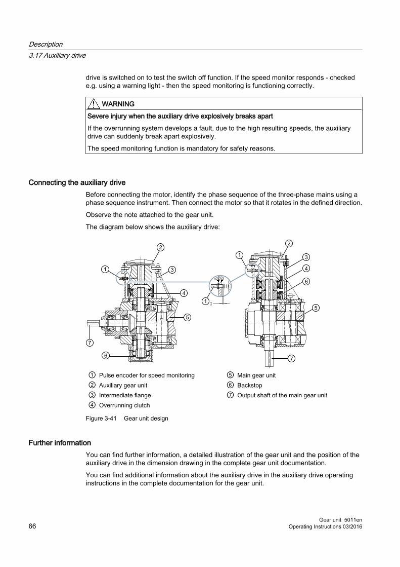
drive is switched on to test the switch off function. If the speed monitor responds - checked e.g. using a warning light - then the speed monitoring is functioning correctly.
WARNING
Severe injury when the auxiliary drive explosively breaks apart
If the overrunning system develops a fault, due to the high resulting speeds, the auxiliary drive can suddenly break apart explosively.
The speed monitoring function is mandatory for safety reasons.
Connecting the auxiliary driveBefore connecting the motor, identify the phase sequence of the three-phase mains using a phase sequence instrument. Then connect the motor so that it rotates in the defined direction.
Observe the note attached to the gear unit.
The diagram below shows the auxiliary drive:
① Pulse encoder for speed monitoring ⑤ Main gear unit② Auxiliary gear unit ⑥ Backstop③ Intermediate flange ⑦ Output shaft of the main gear unit④ Overrunning clutch
Figure 3-41 Gear unit design
Further informationYou can find further information, a detailed illustration of the gear unit and the position of the auxiliary drive in the dimension drawing in the complete gear unit documentation.
You can find additional information about the auxiliary drive in the auxiliary drive operating instructions in the complete documentation for the gear unit.
Description3.17 Auxiliary drive
Gear unit 5011en66 Operating Instructions 03/2016

You can find the precise designation of the geared motor and the mounting position in the dimension drawings in the complete gear unit documentation.
3.17.1 Overrunning clutchIf, in addition to the main drive, you couple an auxiliary drive to the gear unit, then this coupling is realised using an overrunning clutch.
When the auxiliary drive is used to drive the gear unit, the overrunning clutch allows torque to be transferred in one direction of rotation, while "free-wheeling operation" applies when driven by the main drive.
The output shaft of the main drive rotates in the same direction of rotation, irrespective of whether the main drive is used or the auxiliary drive.
Principle of operationThe overrunning clutch as centrifugally-operated sprags. When the main gear unit rotates with the specified direction of rotation, the inner ring with the sprags rotates, while the outer ring remains stationary. Above a certain speed the sprags disengage, and the overrunning clutch operates without any wear.
When the auxiliary unit drive motor is used as drive via the outer ring, then the overrunning clutch is also driven; this means that the main gear unit is slowly rotated in the selected direction of rotation. In this case, the input shaft of the main gear unit and the main motor simultaneously also slowly rotate when a flexible coupling is used between the main motor and gear unit.
Note
Electrically interlock the main motor and the auxiliary drive motor so that only one of the two motors can be switched on.
Note
When driven by the auxiliary drive, then the input shaft of the main gear unit also slowly rotates. It is not permissible that this rotary motion is prevented. A brake located on the drive side in the main drive must be opened when driven by the auxiliary drive.
NOTICE
Damage to or destruction of the overrunning clutch
Damage to or destruction of the overrunning clutch as a result of increased wear due to operation below disengagement speeds is possible.
Regularly replace the overrunning clutch when operating the gear unit at speeds below the disengagement speed of the overrunning clutch. Data indicating the replacement intervals is provided in the dimension drawing and on a notice plate attached to the gear unit. This plate is attached to the gear unit housing near the overrunning clutch.
Description3.17 Auxiliary drive
Gear unit 5011enOperating Instructions 03/2016 67

Oil supply for the overrunning clutchThe overrunning clutch is accommodated in an intermediate flange, and is supplied with oil from the main gear unit.
Description3.17 Auxiliary drive
Gear unit 5011en68 Operating Instructions 03/2016

Application planning 44.1 Scope of delivery
The scope of delivery is listed in the shipping documents. Immediately upon receiving the gearbox, check that everything has been delivered. Report any damaged and/or missing parts to Customer Services (Page 155) immediately.
WARNING
Serious injury through defective product
Serious injury may occur.
If the gearbox exhibits any visible damage, you should not put it into operation.
4.2 Transport
General informationThe gear unit is delivered fully assembled. Additional items such as shrink disks, couplings, oil coolers, pipework and valves may be delivered separately packaged, as necessary.
When transporting the gear unit, observe the following instructions to avoid damaging the gear unit:
● Always use suitable equipment to transport the gear unit.
● Transport the gear unit without oil filling and leave it in the transport packaging.Depending on the order specification, the gear unit can be shipped filled with oil. Take the extra weight into account (number of litres x 10 N) and transport the gear unit in its final mounting position.
● Do not use incorrect attachment points.The threads in the end faces of the shaft ends may not be used for attaching lifting equipment.
● Do not use the pipework to move the gear unit.
● Ensure that the lifting equipment is adequately designed to accommodate the weight of the gear unit.
● Always set the gear unit down onto a suitable base.The base must be designed such that there is no risk of damage to the gear unit or its mounted components.
Gear unit 5011enOperating Instructions 03/2016 69

WARNING
Risk of crushing
There is a risk of being crushed by a component that becomes detached because the hoisting gear and load suspension device are not suitable for handling it.
When lifting, please observe the load distribution information on the packaging.
When the product is in a raised position, transport it slowly and carefully to avoid injury to persons or damage to the gear unit.
Attaching the gear unitTo transport the gear unit, only attach slings to the marked attachment points that are provided for this purpose.
Please observe the following when attaching slings to the load or raising, lowering or moving it:
● Do not exceed the specified load limits
● If you are using a load suspension device with several load hooks, make sure that the load is evenly distributed between them
● Note the eccentric centre of gravity
● Make sure that the lifting equipment is securely attached
● Keep your speed down when moving the load
● Do not allow the load to sway and do not attach the load to objects or structures inside the building
● Loads must not be suspended from the tip of a load hook
● Always place the products down on a level, non-slip and stable base
DANGER
Falling load
There is a risk of fatal injury from falling loads if these have not been securely attached to the lifting equipment.
Never stand or sit under suspended loads. Do not exceed the load limits of the lifting equipment.
PackagingThe gear unit is delivered fully assembled. Additional equipment is also delivered separately packaged, as necessary.
The gear unit may be packed in various forms, depending on the size of the unit and method of transport.
Application planning4.2 Transport
Gear unit 5011en70 Operating Instructions 03/2016

Please adhere to the symbols applied on the packaging.
Figure 4-1 Transport symbols
4.3 Attachment points
Lifting eyesLifting eyes are fitted to the gear unit to assist with its transportation during manufacture and installation.
Carefully ensure that the angle of the vertical load at the gear units lifting eyes does not exceed 45°.
Sling swivelsThreads for screwing in transport lugs are provided on the gear unit to assist with its transportation during manufacture and installation.
The shear pulling must not exceed 45° when the lifting equipment is attached to sling swivels.
Eye boltsThe use of sling swivels instead of eye bolts is generally recommended.
When using eye bolts, please note that their load-bearing capacity may be reduced if they are alternately attached to different components that require moving.
It is not permitted to load eye bolts through lateral pulling contrary to the direction of the eye plane.
The following figure shows the permissible shear and lateral pulling when using eye bolts:
Application planning4.3 Attachment points
Gear unit 5011enOperating Instructions 03/2016 71

A Permitted shear pulling in direction of eye plane (maximum angle of 45°)B Non-permitted lateral pulling contrary to direction of eye plane
Figure 4-2 Shear and lateral pulling when using eye bolts
Position of attachment pointsThe diagram below shows the position of the attachment points on type H..V and B..V gear units:
Figure 4-3 Position of the attachment points on type H..V and B..V gear units
The diagram below shows the position of the attachment points on type H..V gear units with motor:
Application planning4.3 Attachment points
Gear unit 5011en72 Operating Instructions 03/2016

Figure 4-4 Position of the attachment points on type H..V gear units with motor
The diagram below shows the position of the attachment points on type B..V gear units with motor:
Figure 4-5 Position of the attachment points on type B..V gear units with motor
The diagram below shows the position of the attachment points on type H..V gear units in a piggyback configuration:
Application planning4.3 Attachment points
Gear unit 5011enOperating Instructions 03/2016 73

Figure 4-6 Position of the attachment points on type H..V gear units in a piggyback configuration
Drive units with additional components mounted on the gear unit (such as drive motor, coupling, etc.) may require an extra attachment point owing to the displacement in the centre of gravity caused by the mounted components.
Further informationFurther information and a detailed illustration of the gear unit and the position of the attachment points can be found in the drawings in the complete documentation for the gear unit.
4.4 Special aspects of gear unit lubrication and preservation
4.4.1 Regreasing rolling-contact bearings
4.4.1.1 Grease-lubricated rolling-contact bearingThe gear unit can be equipped with grease-lubricated rolling-contact bearings.
Grease-lubricated rolling-contact bearings are filled with grease prior to shipment. Please refer to the plates at the regreasing points for information about grease quantities and regreasing intervals.
4.4.1.2 Grease-lubricated rolling-contact bearing in oil retaining pipeWhen shipped from the factory, the lower output shaft bearing of the gear unit is filled with grease.
The diagram below shows the lubrication point for the lower output shaft bearing on type H..V gear units with oil retaining pipe:
Application planning4.4 Special aspects of gear unit lubrication and preservation
Gear unit 5011en74 Operating Instructions 03/2016

① Lubrication point ② Grease-lubricated rolling-contact bearing
Figure 4-7 Lubrication point for the lower output shaft bearing on type H..V gear units with oil retaining pipe
The diagram below shows the lubrication point for the lower output shaft bearing on type B..V gear units with oil retaining pipe:
① Lubrication point ② Grease-lubricated rolling-contact bearing
Figure 4-8 Lubrication point for the lower output shaft bearing on type B..V gear units with oil retaining pipe
If the gear unit was non-operational for longer than 36 months, or if the lower output shaft bearing was inspected or replaced, then the rolling-contact bearing space must be refilled with the quantity of rolling-contact bearing grease listed in the table. Find the correct oil grade listed in Table "T 7300" on the Internet (http://support.automation.siemens.com/WW/view/de/44231658).
The following table lists the grease quantities (guide value in kg) for the lower output shaft bearing if taken out of service for > 36 months:
Table 4-1 Grease quantities for the lower output shaft bearing if taken out of service for > 36 months:
Type Grease quantity for gear unit size5 6 7 8 9 10 11 12 13 14 15 16
H.BVH.AVB.BVB.AV
0.45 0.45 0.55 0.50 1.30 1.40 2.00 2.30 2.50 2.70 4.25 4.30
H.SVB.SV
0.20 0.25 0.30 0.40 0.50 0.70 0.90 1.20 1.60 1.90 2.00 2.00
Application planning4.4 Special aspects of gear unit lubrication and preservation
Gear unit 5011enOperating Instructions 03/2016 75

The grease quantities for gear unit sizes ≤ 4 and ≥ 17 and for other versions of output shaft are available on request.
The lubrication points are marked by the following sign:
Figure 4-9 Sign: Lubrication point
Further informationAdditional information and a detailed illustrated description of the gear unit can be found in the dimension drawing in the complete gear unit documentation.
4.4.2 Oil filling and oil drain
The diagram below shows the oil filling locations and oil drain locations on a type H.BV aerator gear unit:
① Venting point ③ Oil filling point② Oil dipstick ④ Oil draining point
Figure 4-10 Oil filling and oil drain on H.BV aerator gear unit
The diagram below shows the oil filling locations and oil drain locations on a type B.BV aerator gear unit:
Application planning4.4 Special aspects of gear unit lubrication and preservation
Gear unit 5011en76 Operating Instructions 03/2016

① Venting point ③ Oil filling point② Oil dipstick ④ Oil draining point
Figure 4-11 Oil filling and oil drain locations on H.BV aerator gear unit
Further informationFurther information and a detailed illustrated description of the gear unit can be found in the dimension drawing in the complete documentation for the gear unit.
4.4.3 Special aspects of gear unit preservation
Interior preservation through oil fillingOil filling must not be used as a means of preserving the interior of gear units with an oil retaining pipe or grease-lubricated rolling-contact bearings.
Application planning4.4 Special aspects of gear unit lubrication and preservation
Gear unit 5011enOperating Instructions 03/2016 77

Application planning4.4 Special aspects of gear unit lubrication and preservation
Gear unit 5011en78 Operating Instructions 03/2016
Assembly 55.1 General assembly instructions
The assembly work must be performed very carefully by authorised, trained and suitably instructed personnel. Liability will be disclaimed for damage caused by the incorrect performance of this work.
RequirementsImproper use can damage the gear unit. Be sure to take the following precautions:
● Protect the gear unit against falling objects and from becoming covered over.
● Do not perform any welding work anywhere on the drive.
● Do not use the gear unit as an earthing point for electric-welding operations.
● Use all of the fastening points fitted to the particular unit design.
● Replace any bolts that are no longer fit for use by new bolts of the same strength class and type.
● Make sure that sufficient hoisting gear is available.
Mounting position and attachment pointsDuring the actual planning phase, be sure to allow for sufficient space around the gear unit to enable subsequent upkeep and maintenance work. Take suitable measures to ensure that unhindered convection across the housing surface is possible so that the gear unit does not overheat. Leave sufficient space to allow a free flow of air into gear units that are equipped with a fan.
Do not use incorrect attachment points (Page 69). The position of the attachment points are shown in the dimension drawing in the complete documentation for the gear unit. To ensure that the unit is properly lubricated during operation, please observe the mounting position specified in the dimension drawings.
NOTICE
Heating of the gear unit by external heat sources
The gear unit must not be heated by external heat sources (exposure to direct sunlight, for example) while it is in operation and measures must be taken where necessary to protect it.
You can take the following measures to protect the gear unit against this hazard:● A sun shield● An additional cooling device● A temperature monitoring device with trip function in the oil sump
If you use a sun shield, this may cause a build-up of heat.
Gear unit 5011enOperating Instructions 03/2016 79

If you use a temperature monitoring device, it must be capable of issuing an alarm when the maximum permissible oil sump temperature is reached. It must also be capable of tripping the drive when the maximum permissible oil sump temperature is exceeded. The operator's process might be interrupted when the drive is shut down.
WARNING
Ignition of vapours emitted from solvents.
There is a risk of injury due to ignition of vapours emitted from solvents when carrying out cleaning work.
Please note the following:● Ensure adequate ventilation.● Do not smoke.
5.2 Unpacking the gear unit
Introduction The scope of delivery is listed in the shipping documents.
WARNING
Risk of serious injury due to defective product
A defective gear unit can result in serious injury.
Do not put the gear unit into operation if any damage is visible.
Contact Customer Services (Page 155).
RequirementsCheck that everything has been delivered immediately upon receipt.
NOTICE
Damage to the gear unit due to corrosion
Exposing the gear unit to moisture can result in damage from corrosion.
Do not damage or open the packaging prematurely if the packaging is designed to preserve the unit.
Assembly5.2 Unpacking the gear unit
Gear unit 5011en80 Operating Instructions 03/2016

ProcedureTo unpack and use the gear unit, proceed as follows:
1. Remove packaging and transport devices in accordance with regulations.
2. Perform a visual inspection for damage and accumulations of dirt.
3. Immediately report any damaged and/or missing parts to Customer Services (Page 155).
4. Dispose of packaging material and transport devices in accordance with regulations.
5.3 Gear unit assembly
5.3.1 Foundation
Properties of the foundationThe foundation must have the following properties:
● Horizontal and level
● Stability
● Designed for torsional rigidity
● Reaction forces from the gear unit must be braced
Requirements of the foundationThe foundation must meet the following requirements:
● Construct the foundation in such a way that it does not generate any resonance vibrations and that it is isolated against the transmission of vibrations from adjacent foundations.
● Design the foundation according to the relevant weight and torque, taking into account the forces acting on the gear unit.
● Align the foundation carefully with the equipment installed on the input and output sides of the gear unit.
● Take into account any elastic deformation that may be caused by operating forces.
● Install lateral stops to prevent displacement if external forces are acting on the gear unit.
Assembly5.3 Gear unit assembly
Gear unit 5011enOperating Instructions 03/2016 81

NOTICE
Lack of stable foundation for the gear unit
Damage to the gear unit is possible if it is not mounted on a stable foundation.
Use bolts of at least strength class 8.8. Information and guidance on the tightening torque can be found in chapter Tightening procedure (Page 127). Tighten the fastening bolts and nuts to the specified tightening torque. When tightening the fastening bolts, make sure that the gear unit is free of mechanical stress.
Further informationFurther information about dimensions, space requirements and arrangement of supply connections can be found in the complete documentation for the gear unit.
5.3.2 Description of assembly work
Measures to be taken prior to assembly
CAUTION
Risk of chemical burns due to chemical substances
There is a risk of chemical burns when handling aggressive cleaning agents.
Please observe the manufacturer's guidelines on how to handle cleaning agents and solvents. Wear suitable protective equipment (gloves, safety goggles). Please use binding agents to immediately clear up any spilt solvent.
WARNING
Risk of burns
There is a risk of serious burn injury from hot surfaces (> 55 °C).
Wear suitable protective gloves and protective clothing.
Improper use can damage the gear unit. Be sure to take the following precautions:
● Use a suitable cleaning agent to remove the corrosion protection from the shafts and mounting surfaces.
● Do not allow the cleaning agent to come into contact with the shaft-sealing rings.
● Use an assembly fixture to mount the input and output elements (e.g. coupling components) onto the shafts and lock them securely.
● Do not use force (hammer blows, etc.) to fit the coupling components as this can cause internal damage to the gear unit.
Assembly5.3 Gear unit assembly
Gear unit 5011en82 Operating Instructions 03/2016

● Take care not to damage the shaft sealing rings or shaft running surfaces when fitting the coupling components.
● If the input and output elements must be heated before assembly, the joining temperatures required are listed in the dimension drawings in the coupling operating instructions.
● Unless otherwise specified, heat the coupling parts by an induction heater, with a torch or in an oven.
● Use heat shields designed to protect against radiant heat in order to safeguard the shaft sealing rings against damage or heating to above 100 °C.
● The elements must be quickly pulled onto the shaft as far as stated in the dimension drawing prepared in accordance with order specifications.
● Use suitable hoisting gear to place the gear unit in position.
NOTICE
Poor alignment
The gear unit or individual components can be damaged as a result of poor alignment.
When installing and mounting the drive ensure that the individual components are precisely aligned with one another.
Inadmissibly high alignment errors of the shaft ends to be connected as a result of angular or axial offset result in premature wear and material damage. Base frames or substructures that are too soft can cause the coupling parts to become radially or axially displaced during operation. This displacement is not measurable when the drive is at a standstill.
The following figure shows the gap dimension at the grease labyrinth:
Figure 5-1 Gap dimension at grease labyrinth
NOTICE
Sparking, inadmissible temperature rise and shaft seal wear due to insufficient gap dimension
An insufficient gap dimension can cause sparking, inadmissible temperature rise and shaft seal wear.
If the shaft is sealed by taconite or Tacolab seals, make sure that the set gap dimension of 1 mm at the grease labyrinth is not altered when the input and output elements (e.g. coupling components) are installed. Rotating and stationary parts must not touch.
Assembly5.3 Gear unit assembly
Gear unit 5011enOperating Instructions 03/2016 83

Further information Further information about removing the corrosion protection can be found in the operating instructions BA 7300 in the complete documentation for the gear unit.
Additional information on how gear units should be attached which, as a result of their weight, require a crane or lifting gear, is provided in chapter Application planning (Page 69).
If the gear unit is to be transported with mounted parts and components, then it may be necessary to use additional attachment points. The position of these attachment points can be found in the dimension drawing in the complete documentation for the gear unit.
5.3.2.1 Alignment
IntroductionDepending on the order specification, the top of the housing has machined surfaces (alignment surfaces) to assist with provisional alignment of the gear unit in the horizontal direction.
DANGER
Risk of fatal injury from flying fragments
Failure to align the unit with the required degree of accuracy can cause the shaft to rupture. A ruptured shaft can result in serious or even fatal injuries.
Align the gear unit exactly so that it conforms to the specified alignment values.
Damage to the gear unit or its components or mounted parts is possible.
The accuracy of the alignment between the shaft axes largely determines the service life of the shafts, bearings and couplings. Please therefore always endeavour to achieve zero deviation in the alignment of the shaft axes (does not apply to ZAPEX couplings or cardan shafts). In this context, please also refer to the relevant operating instructions for further information about, for example, the requirements of couplings.
Procedure The gear unit can be equipped with alignment threads in the housing feet to make it simpler to align.
Figure 5-2 Alignment surface
Assembly5.3 Gear unit assembly
Gear unit 5011en84 Operating Instructions 03/2016

To align the gear unit by its alignment surface, proceed as follows:
1. For the precise position of the alignment surfaces, refer to the dimension drawings in the complete documentation.
2. Note the values inscribed in the alignment surfaces.
3. Use these surfaces as a guide for aligning the gear unit horizontally to ensure that it will run smoothly.
The following diagram shows the alignment surfaces at the gear unit:
① Alignment surfaces
Figure 5-3 Alignment surfaces
Further informationFurther information and a detailed illustrated description of the gear unit can be found in the dimension drawing in the complete documentation for the gear unit.
Tools The following tools are needed to perform the final fine alignment (Page 118) work on the shaft axes of the gear unit and the equipment installed on the input and output sides.
● Rulers
● Spirit level
● Dial gauge
● Laser alignment system
● Feeler gauge etc.
Once the gear unit is finely aligned, tighten the foundation bolts and check the settings again. Record the alignment dimensions and keep the report in a safe place together with these operating instructions.
Assembly5.3 Gear unit assembly
Gear unit 5011enOperating Instructions 03/2016 85

5.3.3 Gear unit assembly on housing foot
5.3.3.1 Installation on a foundation frame
RequirementsThe following requirements must be fulfilled before the assembly work commences:
● The foundation must be horizontal and level.
● When tightening the fastening bolts, make sure that the gear unit is free of mechanical stress.
NOTICE
Poor stability
Damage to the gear unit is possible if it is not mounted on a stable foundation.
Make sure that the foundation frame is horizontal and level. It is particularly important that the surface on which the gear unit is mounted is level because this determines the contact pattern of the teeth and the load on the bearings, and so has an influence on the service life of the gear unit. All points on the gear unit mounting surface must lie between two imaginary parallel planes that are 0.1 mm per 1 m apart.
Design the foundation frame according to the relevant weight and torque, taking into account the forces acting on the gear unit. The feet of the gear unit must be properly supported. Base frames or substructures that are too soft can result in radial or axial displacement during operation. This displacement is not measurable when the drive is at a standstill.
ProcedureTo install the gear unit on a foundation frame, proceed as follows:
1. Clean the underside of the gear unit feet.
2. Use suitable hoisting gear to set the gear unit down on the foundation frame.
3. Tighten the foundation bolts to the specified tightening torque (Page 129). If necessary, install stops to prevent displacement.
4. Align the gear unit precisely with the input and output equipment (Page 84).
5. Record the alignment dimensions.
6. Keep the report in a safe place together with these operating instructions.
Assembly5.3 Gear unit assembly
Gear unit 5011en86 Operating Instructions 03/2016

NOTICE
Damage caused by unevenly tightening the fastening bolts
The gear unit can be damaged by unevenly tightening the fastening bolts.
Evenly tighten the fastening bolts. When tightening the fastening bolts, make sure that the gear unit is free of mechanical stress.
5.3.3.2 Mounting on a concrete foundation using stone bolts or foundation blocks
RequirementsThe lower side of the gear unit mounting feet must be clean.
Mounting a gear unit using stone boltsThe following diagram shows a stone bolt:
① Washer ④ Foundation② Hexagon nut ⑤ Stone bolt③ Gear unit foot
Figure 5-4 Stone bolt
Proceed as follows to mount the gear unit using stone bolts:
1. Attach the stone bolts with washers and hexagon nuts in the foundation mounting points in the gear unit housing.
2. Using a suitable crane or lifting gear, place the gear unit down on the concrete foundation.
3. Align the gear unit so that the input and output shafts are horizontal using shims (Page 84).
4. For higher external forces, if necessary, use lateral stops to prevent the gear unit shifting.
5. Pour concrete into the recesses in the concrete foundation for the stone bolts.
6. After the concrete has set, tighten the hexagon nuts of the stone bolts with the specified tightening torque (Page 129).
7. Record the alignment dimensions and keep the report in a safe place together with these operating instructions.
Assembly5.3 Gear unit assembly
Gear unit 5011enOperating Instructions 03/2016 87

NOTICE
Damage caused by unevenly tightening the hexagon nuts
The gear unit can be damaged by unevenly tightening the hexagon nuts.
Evenly tighten the hexagon nuts. Ensure that the gear unit is not deformed or distorted when tightening the fastening bolts.
Mounting gear units using foundation blocksThe following diagram shows a foundation block:
① Fastening bolt ⑥ Foundation② Washer ⑦ Foundation block③ Gear unit foot ⑧ Flat steel plate④ Height of the completed foundation ⑨ Set screw⑤ Height of the prepared foundation
Figure 5-5 Foundation block
Proceed as follows to mount the gear unit using foundation blocks:
1. Attach the foundation blocks with washers and fastening bolts in the foundation mounting points in the gear unit housing.
2. Tighten the fastening bolts until the housing feet are lying flat on the foundation blocks.
3. Using a suitable crane or lifting gear, place the gear unit down on the concrete foundation.
4. Align the gear unit so that the input and output shafts are horizontal using the set screws (if available) (Page 84).
5. For higher external forces, if necessary, use lateral stops to prevent the gear unit shifting.
6. Before casting the foundation, close the openings in the foundation blocks using a suitable material (e.g. using polystyrene).
7. Pour concrete into the recesses in the concrete foundation for the foundation blocks.
Assembly5.3 Gear unit assembly
Gear unit 5011en88 Operating Instructions 03/2016

8. After the concrete has set, tighten the fastening bolts of the foundation blocks with the specified tightening torque (Page 129).
9. Record the alignment dimensions and keep the report in a safe place together with these operating instructions.
NOTICE
Damage caused by unevenly tightening the fastening bolts
The gear unit can be damaged by unevenly tightening the fastening bolts.
Evenly tighten the fastening bolts. Ensure that the gear unit is not deformed or distorted when tightening the fastening bolts.
5.3.3.3 Mounting on a concrete foundation using anchor bolts
RequirementsThe lower side of the gear unit mounting feet must be clean.
Inserting the anchor boltThe following diagram shows the inserted anchor bolt:
① Baseplate ⑤ Anchor bolt② Support ⑥ Pressure plate③ Fine-grout concrete ⑦ Wood④ Raw foundation ⑧ Hexagon nut
Figure 5-6 Inserted anchor bolt
Proceed as follows to insert the anchor bolt:
1. Place the support on the baseplate embedded in the fine-grout concrete.
2. Insert the anchor bolt.
Assembly5.3 Gear unit assembly
Gear unit 5011enOperating Instructions 03/2016 89

3. Attach the pressure plate and tighten the nuts.
4. Place a piece of wood under the anchor bolt so that it is approximately 10 mm from the upper edge of the support.
5. Using suitable lifting gear, set the gear unit down in position.
Mounting the gear unit using anchor boltsThe following diagram shows a tightened anchor bolt:
① Hexagon nut ⑤ Raw foundation② Washer ⑥ Anchor bolt③ Housing foot ⑦ Baseplate④ Fine-grout concrete ⑧ Support
Figure 5-7 Tightened anchor bolt
Proceed as follows to mount the gear unit using anchor bolts:
1. Pull the anchor bolts upwards. To do this you can use a screw or threaded bar that you screw into the thread on the end face.
2. Attach the washer.
3. Screw on the hexagon nut by hand a few turns.
4. Align the gear unit with the supports (Page 84).
– Observe the values on the alignment strips.
– Maintain the alignment tolerances to the units connected at the input and output according to the permissible angular and axial displacements of the couplings.
5. Document the alignment dimensions in the form of a report, and archive this together with these instructions.
6. Keep the anchor bolts in their position by tightening the nuts by hand.
7. Locate the protective sleeve.
8. Attach the hydraulic clamping device.
Assembly5.3 Gear unit assembly
Gear unit 5011en90 Operating Instructions 03/2016

9. Tighten the screws alternating, taking into account the preload forces (Page 129).
10.Tighten the hexagon nuts to their end stops using a suitable tool.
11.Document the tensioning pressures and preload forces, and archive this report together with these instructions.
CAUTION
Incorrect use of the preload tool
Incorrectly using the preload tool can result in injury.
To ensure correct handling and adjustment of the preload tool, you must carefully comply with the instructions provided in the manufacturers operating instructions for the preload tool.
NOTICE
Inadequate concrete hardness and strength
Damage caused by inadequate stability of the gear unit as a result of inadequate concrete hardness and strength is possible.
The fine-grout concrete must be allowed to harden for at least 28 days before tensioning the anchor bolts.
5.3.4 Mounting on a mounting flange or block flange
5.3.4.1 Mating flange on the machine side
Measures to be taken prior to assemblyBe sure to take the following precautions before mounting the mating flange on the machine side:
● Design and construct the mating flange so that no resonant vibration occurs - and no shock and vibration can be transmitted from adjacent foundations.
● The mating flange assembly that is to be mounted on the gear unit must be torsionally stiff.
● Design the mating flange assembly according to the relevant weight and torque, taking into account the forces acting on the gear unit.
● Very carefully align the units connected at the input ‐ and output - and take into account, where relevant, any elastic deformation as a result of the operational forces.
Poor alignmentThe gear unit can be damaged as a result of poor mating flange alignment.
Assembly5.3 Gear unit assembly
Gear unit 5011enOperating Instructions 03/2016 91

The mating flange must be absolutely horizontal and level. When tightening the fastening bolts, make sure that the gear unit is free of mechanical stress.
NOTICE
Poor stability
Damage to the gear unit is possible if it is not mounted on a stable foundation.
Tighten the fastening bolts and nuts to the specified tightening torque (Page 129).
Always use bolts with a strength class (property class) of 8.8.
Further informationYou can find additional information on dimensions, space requirement and arrangement of the supply connections (for example, separately supplied oil cooling systems) in the dimension drawings in the complete documentation for the gear unit.
5.3.4.2 Assembly
RequirementsBefore commencing with the assembly work, make sure that you have done the following:
● A centring shoulder (∅ d3) is provided on the mounting or block flange on the output side on gear units with a solid shaft or flange shaft on the output side. Machine a bore that matches this centring shoulder in the mating flange on the machine side. Detailed specifications for the centring shoulder and the bore can be found in the dimension drawing in the complete documentation for the gear unit.
● A centring shoulder (∅ d3) is provided on the mounting or block flange on the output side on gear units with a hollow shaft on the output side. Proceed as follows:
– If the machine shaft is supported by bearings at one end only, machine a bore that matches this centring shoulder in the mating flange on the machine side. The gear unit assumes the function of the second bearing support point. Detailed specifications for the centring shoulder and the bore can be found in the dimension drawing in the complete documentation for the gear unit.
– If the machine shaft is located in two bearings in the mating flange on the machine side, centring the gear unit (centring shoulder ∅ d3) in the mating flange is not permissible (due to redundancy).
● When aligning the machine shaft with the mating flange, keep the radial and angular misalignment as low as possible.
● The area around the face of the mounting and mating flanges must be absolutely free of any grease. The reliability with which torque is transmitted depends to a large extent on this.
Assembly5.3 Gear unit assembly
Gear unit 5011en92 Operating Instructions 03/2016

● Do not use any contaminated solvents or soiled cleaning cloths, nor any cleaning agents that contain oil (such as petroleum or turpentine) to degrease the surfaces.
● The transmittable gear unit torque is restricted by the bolted connection on the hole circle K1.
DANGER
Risk of fatal injury from flying fragments
Non-adherence to the alignment accuracy can result in a broken shaft and as a consequence risk to life and injury.
Align the gear unit exactly so that it conforms to the specified alignment values.
Damage to the gear unit or its components or mounted parts is possible.
The service life of the shafts and rolling-contact bearings essentially depends on the alignment accuracy of the machine shaft to the mating flange. As a consequence, always try to achieve a zero deviation.
CAUTION
Risk of injury due to chemical substances
Observe the manufacturer’s guidelines on how to handle lubricants and solvents.
Wear suitable protective clothing.
NOTICE
Damage to the gear unit by uneven tightening of the flange bolts
The gear unit can be damaged by unevenly tightening the flange bolts.
Tighten the flange bolts diagonally to the specified torque. When tightening the flange bolts, make sure that the gear unit is free of mechanical stress.
ProcedureProceed as follows to install the gear unit:
1. Clean the contact surfaces of the mounting or block flange of the gear unit and the mating flange on the machine side.
2. Inspect the shaft for damaged bearing seats and edges. If necessary, rework the components with an appropriate tool and then clean them again.
3. Using suitable lifting gear, set the gear unit down on the mating flange on the machine side.
4. For gear units with hollow shafts, follow the assembly instructions given in chapter Shaft-mounted gear unit with hollow shaft (Page 99).
Assembly5.3 Gear unit assembly
Gear unit 5011enOperating Instructions 03/2016 93

5. If necessary, make sure that the locating spigots of the flanges are interlocked.
6. Tighten the flange bolts diagonally and evenly to the specified torque. Please refer to Tightening torques and preload forces (Page 129) for the correct tightening torque.Always use bolts with a strength class (property class) of at least 8.8.
NOTICE
Damage caused by centring the gear unit in the mating flange
The gear unit can be damaged by centring the gear unit (centring shoulder ∅ d3) in the mating flange.
With a hollow shaft on the output side and a machine shaft that is also located in two bearings in the mating flange on the machine side, centring the gear unit (centring shoulder ∅ d3) in the mating flange is not permissible (due to redundancy).
Further informationYou will find more information about permissible tolerances in the relevant operating instructions in the complete documentation for the gear unit.
Gear units with solid shaft or flange shaft on the output sideThe diagram below shows gear units with a solid shaft or flange shaft on the output side:
① Mounting flange ② Block flange
Figure 5-8 Gear units with solid shaft or flange shaft on the output side
Assembly5.3 Gear unit assembly
Gear unit 5011en94 Operating Instructions 03/2016

Gear units with a hollow shaft on the output sideThe diagram below shows gear units with a hollow shaft on the output side:
① Mounting flange ② Block flange
Figure 5-9 Gear units with a hollow shaft on the output side
Axial lockingDepending on the version, lock the hollow shaft axially on the machine shaft (e.g. by a locking ring, end plate, adjusting screw).
5.3.4.3 Dismantling
Measures prior to dismantling
NOTICE
Damage to the gear unit due to skewing
The gear unit can become damaged if it skews during dismantling.
Do not allow the gear unit to skew when you remove it from the machine shaft. When removing the gear unit using hydraulic pulling equipment, excessive force can be placed on the housing, rolling-contact bearings and other gear unit components. Always check the hollow shaft bearings for damage before reattaching the gear unit to the machine shaft.
NoteReducing the risk of corrosion
When using jacking screws or screw spindles, round off and grease the end of the thread (head) that presses against the driven machine to avoid the risk of corrosion.
Assembly5.3 Gear unit assembly
Gear unit 5011enOperating Instructions 03/2016 95

ProcedureTo dismantle the gear unit with mounting and block flange from the machine shaft, proceed as follows:
1. Secure the gear unit in position.
2. Remove the flange bolts.
3. For gear units with hollow shafts, follow the dismantling instructions given in chapter Shaft-mounted gear unit with hollow shaft (Page 99).
5.3.5 Mounting the coupling flange on the output side on type H.BV and B.BV gear units
5.3.5.1 RequirementsEnsure that the following measures are applied before mounting the coupling flange on the output side:
● The area around the face of the coupling flange must be absolutely free of any grease. The reliability with which torque is transmitted depends to a large extent on this.
● Do not use any contaminated solvents or soiled cleaning cloths, nor any cleaning agents that contain oil (such as petroleum or turpentine) to degrease the surfaces.
NOTICE
Damage to the gear unit by uneven tightening of the connecting bolts
The gear unit can be damaged by unevenly tightening the connecting bolts.
Tighten the connecting bolts diagonally and evenly to the specified torque. When tightening the connecting bolts, make sure that the gear unit is free of mechanical stress.
5.3.5.2 Installing the gear unit
ProcedureTo mount a gear unit with a coupling flange on the output side, proceed as follows:
1. Clean the contact surfaces of the coupling flange and the mating flange.
2. Using suitable lifting gear, set the gear unit down on the mating flange.
3. Make sure that the flanges are centred.
4. Tighten the connecting bolts diagonally and evenly to the specified torque.
Assembly5.3 Gear unit assembly
Gear unit 5011en96 Operating Instructions 03/2016

The following table lists the tightening torques at the flange connections.
Table 5-1 Tightening torques at the flange connections
Thread size Strength class Tightening torqueM20 10.9 610 NmM24 10.9 1 050 NmM30 10.9 2 100 NmM36 10.9 3 560 Nm
Further informationYou can find additional information about the tightening torque of the connecting bolts in the dimension drawings in the coupling operating instructions. Replace any bolts that are no longer fit for use by new bolts of the same strength class and type.
5.3.6 Mounting the torque arm for the gear unit housing
5.3.6.1 Mounting the torque armFor all shaft-mounted gear units, absorb the reaction torque corresponding to the torque of the machine – and which acts in an opposite direction at the housing.
5.3.6.2 Mounting the torque arm
NOTICE
Damage to the gear unit due to incorrect mounting of the motor and torque arm
Damage to the gear unit due to incorrect mounting of the motor and torque arm is possible
The motor and torque arm may only be mounted after prior consultation with Siemens. Mount the torque arm to the machine side without causing any distortion or deformation.
Mount the torque arm to the machine side in such a way that it is free of mechanical stress.
The diagram below shows the torque arm for the gear unit housing:
Assembly5.3 Gear unit assembly
Gear unit 5011enOperating Instructions 03/2016 97

① Machine side ② Elastic pedestal
Figure 5-10 Torque arm for the gear unit housing
The following table lists the motor assignment for the housing support:
Table 5-2 Motor assignment for housing support
Gear unit size
Largest permissible standard motor for the relevant gear unit typeH2 H3 H4 B2 B3 B4
1 - - - 112 - -2 - - - 132 - -3 200 - - 180 180 -4 225 - - 200 200 -5 ... 6 250 250 - 225 225 -7 ... 8 315M 315M 180 280 280 2009 ... 10 315M 315M 225 280 280 22511 ... 12 315M 315M 250 315M 315M 28013 ... 14 355 355 315M 355 355 315M15 ... 16 - 355 315 - 355 355M17 ... 18 - 355 355M - 355 35519 ... 22 On request
Larger motors may be mounted only after consultation with Siemens.
Further information Further information about constructing the foundation for gear units with a torque arm can be found in chapter Foundation (Page 81).
Assembly5.3 Gear unit assembly
Gear unit 5011en98 Operating Instructions 03/2016

5.4 Shaft-mounted gear unit with hollow shaft
5.4.1 Shaft-mounted gear unit with hollow shaft and parallel keyway
IntroductionThe shaft end of the driven machine shaft (material C60+N or higher strength) must have a parallel key as defined by DIN 6885, Part 1, form A. Furthermore, it should have a hole centred in its end face as defined by DIN 332, form DS (with thread). The connection dimensions for the driven machine shaft can be found in the dimension drawing in the complete documentation.
5.4.1.1 PreparationsTo facilitate dismantling (Page 102), Siemens recommends that you insert a pressure oil connector into the shaft end of the driven machine until it is flush with the bore of the hollow shaft. This connector can also be used to feed in rust remover. Failure to heed this recommendation shall not impose any liability on the plant constructor vis-à-vis the plant operator.
The following diagram illustrates the preparations required for gear units with a hollow shaft and parallel keyway:
① Hollow shaft ③ Parallel key② Pressure oil connector ④ Machine shaft
Figure 5-11 Gear unit with a hollow shaft and parallel keyway
Assembly5.4 Shaft-mounted gear unit with hollow shaft
Gear unit 5011enOperating Instructions 03/2016 99

5.4.1.2 Assembly
Measures to be taken prior to assembly
CAUTION
Risk of injury due to chemical substances
Observe the manufacturer’s guidelines on how to handle lubricants and solvents.
Wear suitable protective clothing.
Improper use can damage the gear unit. Be sure to take the following precautions:
● Use a suitable cleaning agent to remove the corrosion protection from the hollow shaft and the machine shaft.
● Inspect the hollow and machine shafts for damaged seats and edges.
● If necessary, rework the components with an appropriate tool and then clean them again.
● Apply an appropriate lubricant to the contact surfaces to protect them against fretting corrosion.
NOTICE
Risk of damage to shaft sealing rings from cleaning agent
Aggressive chemical cleaning agents may cause damage to shaft sealing rings.
Do not allow the cleaning agent to come into contact with the shaft-sealing rings.
Mounting
Procedure
NOTICE
Damage to the gear unit
The gear unit can become damaged if it skews during assembly.
The hollow shaft must be flush with the machine shaft during assembly of the gear unit on the machine shaft. Do not allow the gear unit to skew.
Assembly5.4 Shaft-mounted gear unit with hollow shaft
Gear unit 5011en100 Operating Instructions 03/2016
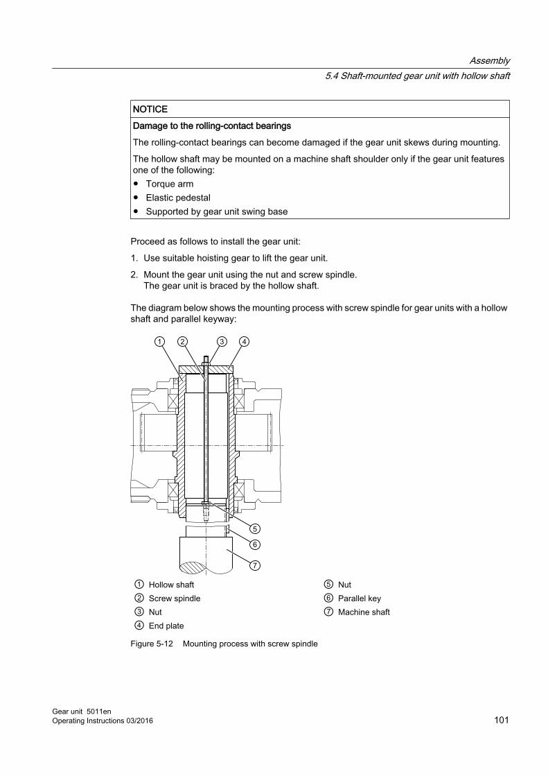
NOTICE
Damage to the rolling-contact bearings
The rolling-contact bearings can become damaged if the gear unit skews during mounting.
The hollow shaft may be mounted on a machine shaft shoulder only if the gear unit features one of the following:● Torque arm● Elastic pedestal● Supported by gear unit swing base
Proceed as follows to install the gear unit:
1. Use suitable hoisting gear to lift the gear unit.
2. Mount the gear unit using the nut and screw spindle.The gear unit is braced by the hollow shaft.
The diagram below shows the mounting process with screw spindle for gear units with a hollow shaft and parallel keyway:
① Hollow shaft ⑤ Nut② Screw spindle ⑥ Parallel key③ Nut ⑦ Machine shaft④ End plate
Figure 5-12 Mounting process with screw spindle
Assembly5.4 Shaft-mounted gear unit with hollow shaft
Gear unit 5011enOperating Instructions 03/2016 101
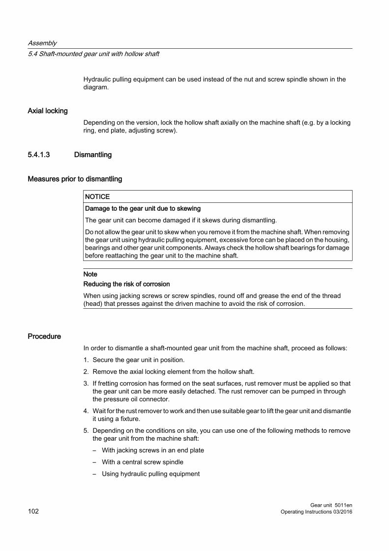
Hydraulic pulling equipment can be used instead of the nut and screw spindle shown in the diagram.
Axial lockingDepending on the version, lock the hollow shaft axially on the machine shaft (e.g. by a locking ring, end plate, adjusting screw).
5.4.1.3 Dismantling
Measures prior to dismantling
NOTICE
Damage to the gear unit due to skewing
The gear unit can become damaged if it skews during dismantling.
Do not allow the gear unit to skew when you remove it from the machine shaft. When removing the gear unit using hydraulic pulling equipment, excessive force can be placed on the housing, bearings and other gear unit components. Always check the hollow shaft bearings for damage before reattaching the gear unit to the machine shaft.
NoteReducing the risk of corrosion
When using jacking screws or screw spindles, round off and grease the end of the thread (head) that presses against the driven machine to avoid the risk of corrosion.
ProcedureIn order to dismantle a shaft-mounted gear unit from the machine shaft, proceed as follows:
1. Secure the gear unit in position.
2. Remove the axial locking element from the hollow shaft.
3. If fretting corrosion has formed on the seat surfaces, rust remover must be applied so that the gear unit can be more easily detached. The rust remover can be pumped in through the pressure oil connector.
4. Wait for the rust remover to work and then use suitable gear to lift the gear unit and dismantle it using a fixture.
5. Depending on the conditions on site, you can use one of the following methods to remove the gear unit from the machine shaft:
– With jacking screws in an end plate
– With a central screw spindle
– Using hydraulic pulling equipment
Assembly5.4 Shaft-mounted gear unit with hollow shaft
Gear unit 5011en102 Operating Instructions 03/2016

The following diagram shows the dismantling procedure using an end plate for gear units with a hollow shaft and parallel keyway:
① End plate for pressing out ④ Parallel key② Jacking screws ⑤ Machine shaft③ Bolts ⑥ Hollow shaft
Figure 5-13 Dismantling using an end plate
Assembly5.4 Shaft-mounted gear unit with hollow shaft
Gear unit 5011enOperating Instructions 03/2016 103

The following diagram shows the dismantling procedure using hydraulic pulling equipment for gear units with hollow shaft and parallel keyway:
① Auxiliary plate for pressing out ⑤ Parallel key② Hydraulic pulling equipment ⑥ Machine shaft③ Screw spindle ⑦ Hollow shaft④ Pressure oil connector
Figure 5-14 Dismantling using hydraulic pulling equipment
End plate and auxiliary plateThe end plate and auxiliary plate for removing the gear unit are not supplied as standard with the gear unit. Both end faces of the hollow shaft have threaded holes for attaching the end plate to the shaft.
Further informationAdditional information and a detailed illustration of the threaded holes can be found in the dimension drawing in the complete gear unit documentation.
Assembly5.4 Shaft-mounted gear unit with hollow shaft
Gear unit 5011en104 Operating Instructions 03/2016

The following diagram shows a hollow shaft with parallel keyway:
Figure 5-15 Hollow shaft with parallel keyway
*) 2 threads offset through 180 °
Threaded holes at the face sides of gear unit hollow shafts Refer to the following table for the dimensions of the threaded holes at the face sides of gear unit hollow shafts:
Table 5-3 Dimensions for the threaded holes at the face sides of gear unit hollow shafts
Gear unit size
m in mm s t in mm Gear unit size
m in mm s t in mm
4 95 M8 14.5 12 215 M12 19.55 115 M8 14.5 13 230 M12 19.56 125 M8 14.5 14 250 M12 19.57 140 M10 17 15 270 M16 248 150 M10 17 16 280 M16 249 160 M10 17 17 300 M16 2410 180 M12 19.5 18 320 M16 2411 195 M12 19.5 ≥ 19 On request
NOTICE
Damage to the gear unit housing or other gear unit components
The gear unit housing or other gear unit components might sustain damage if forcing pressures in excess of the maximum specified values are applied.
When removing a gear unit that is not only supported at the hollow shaft, but also at the housing, the forcing pressures specified in the tables below must not be exceeded. The hollow shaft bearings must always be checked for damage before the gear unit is attached to the machine shaft.
Assembly5.4 Shaft-mounted gear unit with hollow shaft
Gear unit 5011enOperating Instructions 03/2016 105

Maximum forcing pressuresRefer to the following table for the maximum forcing pressures:
Table 5-4 Maximum forcing pressures
Gear unit size Maximum forcing pres‐sures in N
Gear unit size Maximum forcing pres‐sures in N
4 22 600 12 113 6005 33 000 13 140 0006 37 500 14 160 0007 50 000 15 193 0008 56 000 16 215 0009 65 000 17 240 00010 82 000 18 266 00011 97 200 ≥ 19 On request
5.4.2 Shaft-mounted gear unit with hollow shaft and spline according to DIN 5480
IntroductionThe end of the driven machine shaft (material C60+N or higher strength) must have a spline according to DIN 5480. Furthermore, it should have a hole centred in its end face as defined by DIN 332, form DS (with thread). The connection dimensions for the driven machine shaft can be found in the dimension drawing in the complete documentation.
5.4.2.1 PreparationsTo facilitate dismantling (Page 110), Siemens recommends that you insert a pressure oil connector into the shaft end of the driven machine until it is flush with the bore of the hollow shaft. This connector can also be used to feed in rust remover. Failure to heed this recommendation shall not impose any liability on the plant constructor vis-à-vis the plant operator.
The following diagram shows the preparation for gear units with hollow shaft and spline:
Assembly5.4 Shaft-mounted gear unit with hollow shaft
Gear unit 5011en106 Operating Instructions 03/2016

① Pressure oil connector ③ Machine shaft② DU bushing ④ Hollow shaft
Figure 5-16 Preparation for gear units with hollow shaft and spline
5.4.2.2 Assembly
Measures to be taken prior to assembly
CAUTION
Risk of injury due to chemical substances
Observe the manufacturer’s guidelines on how to handle lubricants and solvents.
Wear suitable protective clothing.
Improper use can damage the gear unit. Be sure to take the following precautions:
● Use a suitable cleaning agent to remove the corrosion protection from the hollow shaft and the machine shaft.
● Inspect the hollow and machine shafts for damaged seats and edges.
● If necessary, rework the components with an appropriate tool and then clean them again.
● Apply an appropriate lubricant to the contact surfaces to protect them against fretting corrosion.
Assembly5.4 Shaft-mounted gear unit with hollow shaft
Gear unit 5011enOperating Instructions 03/2016 107

NOTICE
Risk of damage to shaft sealing rings
Aggressive chemical cleaning agents may cause damage to shaft sealing rings.
Do not allow the cleaning agent to come into contact with the shaft-sealing rings.
Mounting with preassembled DU bushing
Procedure
NOTICE
Damage to the gear unit
The gear unit can become damaged if it skews during assembly.
When mounting the gear unit, make sure that the hollow shaft and machine shaft are aligned and ensure that the machine shaft splines and hollow shaft splines match up. You can identify the correct spline position by rotating the input shaft or gently swivelling the gear unit on the hollow shaft.
NOTICE
Damage to the rolling-contact bearings
The rolling-contact bearings can become damaged if the gear unit skews during mounting.
The hollow shaft may be mounted on a machine shaft shoulder only if the gear unit features one of the following:● Torque arm● Elastic pedestal● Supported by gear unit swing base
Proceed as follows to mount the gear unit with integrated DU bushing:
1. Use suitable hoisting gear to lift the gear unit.
2. Mount the gear unit using the nut and screw spindle.The gear unit is braced by the hollow shaft.
Assembly5.4 Shaft-mounted gear unit with hollow shaft
Gear unit 5011en108 Operating Instructions 03/2016
The following diagram shows the mounting process with integrated DU bushing for gear units with a hollow shaft and spline:
① Hollow shaft ⑤ DU bushing② Screw spindle ⑥ Nut③ Nut ⑦ Machine shaft④ End plate
Figure 5-17 Mounting with preassembled DU bushing
Hydraulic pulling equipment can be used instead of the nut and screw spindle shown in the diagram.
Mounting with DU bushing as a separate component
Procedure
NOTICE
Damage to the gear unit
The gear unit can become damaged if it skews during assembly.
When mounting the gear unit, make sure that the hollow shaft and machine shaft are aligned and ensure that the machine shaft splines and hollow shaft splines match up. You can identify the correct spline position by rotating the input shaft or gently swivelling the gear unit on the hollow shaft.
Assembly5.4 Shaft-mounted gear unit with hollow shaft
Gear unit 5011enOperating Instructions 03/2016 109

NOTICE
Damage to the rolling-contact bearings
The rolling-contact bearings can become damaged if the gear unit skews during mounting.
The hollow shaft may be mounted on a machine shaft shoulder only if the gear unit features one of the following:● Torque arm● Elastic pedestal● Supported by gear unit swing base
Proceed as follows to mount the gear unit with hollow shaft and spline onto the driven machine shaft with a DU bushing as a separate component:
1. Use suitable hoisting gear to lift the gear unit.
2. Push the separately supplied DU bushing onto the machine shaft.
3. Use a ratchet tie to tighten the DU bushing until it makes secure contact with the shaft.
4. Move the DU bushing together with the machine shaft into the hollow shaft of the gear unit.
Hydraulic pulling equipment can be used instead of the nut and screw spindle shown in the diagram.
Axial lockingDepending on the version, lock the hollow shaft axially on the machine shaft (e.g. by a locking ring, end plate, adjusting screw).
5.4.2.3 Dismantling
Measures prior to dismantling
NOTICE
Damage to the gear unit
The gear unit can become damaged if it skews during dismantling.
Do not allow the gear unit to skew when you remove it from the machine shaft. When removing the gear unit using hydraulic pulling equipment, excessive force can be placed on the housing, bearings and other gear unit components. Always check the hollow shaft bearings for damage before reattaching the gear unit to the machine shaft.
NoteReducing the risk of corrosion
When using jacking screws or screw spindles, round off and grease the end of the thread (head) that presses against the driven machine to avoid the risk of corrosion.
Assembly5.4 Shaft-mounted gear unit with hollow shaft
Gear unit 5011en110 Operating Instructions 03/2016

ProcedureTo remove the shaft-mounted gear unit with hollow shaft from the machine shaft, proceed as follows:
1. Secure the gear unit in position.
2. Remove the axial locking element from the hollow shaft.
3. If fretting corrosion has formed on the seat surfaces, rust remover must be applied so that the gear unit can be more easily detached. The rust remover can be pumped in through the pressure oil connector.
4. To do this, first remove the end plate and locking ring.
5. Wait for the rust remover to work and then use suitable gear to lift the gear unit and dismantle it using a fixture.
6. Depending on the conditions on site, you can use one of the following methods to remove the gear unit from the machine shaft:
– With jacking screws in an end plate
– With a central screw spindle
– Using hydraulic pulling equipment
The following diagram shows the dismantling procedure using an end plate for gear units with a hollow shaft and spline:
① End plate ④ DU bushing② Jacking screws ⑤ Machine shaft③ Pressure oil connector ⑥ Hollow shaft
Figure 5-18 Dismantling using an end plate
Assembly5.4 Shaft-mounted gear unit with hollow shaft
Gear unit 5011enOperating Instructions 03/2016 111

The following diagram shows the dismantling procedure using hydraulic pulling equipment for gear units with hollow shaft and spline:
① Auxiliary plate for pressing out ⑤ DU bushing② Hydraulic pulling equipment ⑥ Machine shaft③ Screw spindle ⑦ Hollow shaft④ Pressure oil connector
Figure 5-19 Dismantling using hydraulic pulling equipment
NOTICE
Damage to the gear unit housing or other gear unit components
The gear unit housing or other gear unit components might sustain damage if forcing pressures in excess of the maximum specified values are applied.
When removing a gear unit that is not only supported at the hollow shaft, but also at the housing, the forcing pressures specified in the tables below must not be exceeded. The hollow shaft bearings must always be checked for damage before the gear unit is attached to the machine shaft.
Assembly5.4 Shaft-mounted gear unit with hollow shaft
Gear unit 5011en112 Operating Instructions 03/2016

Refer to the following table for the maximum forcing pressures:
Table 5-5 Maximum forcing pressures
Gear unit size Maximum forcing pres‐sures in N
Gear unit size Maximum forcing pres‐sures in N
2 11 700 11 97 2003 15 200 12 113 6004 22 600 13 140 0005 33 000 14 160 0006 37 500 15 193 0007 50 000 16 215 0008 56 000 17 240 0009 65 000 18 266 00010 82 000 ≥ 19 On request
NoteThe auxiliary plate is not delivered as standard with the gear unit.
The auxiliary plate for removing the gear unit is not supplied as standard with the gear unit.
5.4.3 Shaft-mounted gear unit with hollow shaft and shrink disk
IntroductionThe end of the driven machine shaft (material C60+N or higher strength) should have a hole centred in its end face as defined by DIN 332, form DS (with thread). The connection dimensions for the driven machine shaft can be found in the dimension drawing in the complete documentation.
5.4.3.1 Assembly
Measures to be taken prior to assembly
CAUTION
Risk of injury due to chemical substances
Observe the manufacturer’s guidelines on how to handle lubricants and solvents.
Wear suitable protective clothing.
Assembly5.4 Shaft-mounted gear unit with hollow shaft
Gear unit 5011enOperating Instructions 03/2016 113

Improper use can damage the gear unit. Be sure to take the following precautions:
● Use a suitable cleaning agent to remove the corrosion protection from the hollow shaft and the machine shaft.
● Inspect the hollow shaft and machine shaft for damaged seats and edges.
● If necessary, rework the components with an appropriate tool and then clean them again.
NOTICE
Risk of damage to shaft sealing rings
Aggressive chemical cleaning agents may cause damage to shaft sealing rings.
Do not allow the cleaning agent to come into contact with the shaft-sealing rings.
NoteThe bore of the hollow shaft and the machine shaft must be free of any grease
Make sure that the hollow shaft bore and the machine shaft are completely free of grease in the area around the shrink disk seat. The reliability with which torque is transmitted depends to a large extent on this.
Do not use any contaminated solvents or soiled cleaning cloths, nor any cleaning agents that contain oil (such as petroleum or turpentine) to degrease the surfaces.
Pulling on with integrated DU bushing
Procedure
NOTICE
Damage to the gear unit
The gear unit can become damaged if it skews during assembly.
The hollow shaft must be flush with the machine shaft during assembly of the gear unit on the machine shaft. Do not allow the gear unit to skew.
NOTICE
Damage to the rolling-contact bearings
The rolling-contact bearings can become damaged if the gear unit skews during mounting.
The hollow shaft may be mounted on a machine shaft shoulder only if the gear unit features one of the following:● Torque arm● Elastic pedestal● Supported by gear unit swing base
Assembly5.4 Shaft-mounted gear unit with hollow shaft
Gear unit 5011en114 Operating Instructions 03/2016

Proceed as follows to mount the gear unit with hollow shaft and shrink disk onto the driven machine shaft with integrated DU bushing:
1. Use suitable hoisting gear to lift the gear unit.
2. Mount the gear unit using the nut and screw spindle.The gear unit is braced by the end plate in the hollow shaft.
3. Pull on the gear unit with hollow shaft up to the seat below the shrink disk on the machine shaft.The machine shaft centres itself in the seat below the shrink disk and in the DU bushing.
4. Mount the hollow shaft against the machine shaft collar:
The following diagram shows the preparation for gear units with hollow shaft and shrink disk:
① Nut ⑤ Machine shaft② Screw spindle ⑥ Nut ③ End plate ⑦ Hollow shaft④ DU bushing
Figure 5-20 Preparation for gear units with hollow shaft and shrink disk
Parts 1 and 2 are not included in the scope of delivery.
Assembly5.4 Shaft-mounted gear unit with hollow shaft
Gear unit 5011enOperating Instructions 03/2016 115

Mounting with DU bushing as a separate component
Procedure
NOTICE
Damage to the gear unit
The gear unit can become damaged if it skews during assembly.
The hollow shaft must be flush with the machine shaft during assembly of the gear unit on the machine shaft. Do not allow the gear unit to skew.
NOTICE
Damage to the rolling-contact bearings
The rolling-contact bearings can become damaged if the gear unit skews during mounting.
The hollow shaft may be mounted on a machine shaft shoulder only if the gear unit features one of the following:● Torque arm ● Elastic pedestal● Supported by gear unit swing base
Proceed as follows to mount the gear unit with hollow shaft and shrink disk onto the driven machine shaft with a DU bushing as a separate component:
1. Use suitable hoisting gear to lift the gear unit.
2. Push the separately supplied DU bushing onto the machine shaft.
3. Use a ratchet tie to tighten the DU bushing until it makes secure contact with the shaft.
4. Move the DU bushing together with the machine shaft into the hollow shaft of the gear unit.
Hydraulic pulling equipment can be used instead of the nut and screw spindle shown in the diagram.
Axial lockingTightening the shrink disk as per specification ensures that the gear unit is properly axially locked. It is not necessary to install any further axial locking elements.
Assembly5.4 Shaft-mounted gear unit with hollow shaft
Gear unit 5011en116 Operating Instructions 03/2016

5.4.3.2 Dismantling
ProcedureTo remove the shaft-mounted gear unit with hollow shaft and shrink disk from the machine shaft, proceed as follows:
1. Secure the gear unit in position.
2. Dismantle the shrink disk.
3. Lift the gear unit off the machine shaft using jacking screws until the seats under the shrink disk and the DU bushing are exposed.
4. Use suitable hoisting gear to lift the gear unit off the machine shaft.
5.5 Gear unit with type F flange shaft
5.5.1 RequirementsEnsure that the following measures are applied before mounting a gear unit with type F flange shaft:
● The area around the face of the flange shaft and mating flange must be absolutely free of any grease. The reliability with which torque is transmitted depends to a large extent on this.
● Do not use any contaminated solvents or soiled cleaning cloths, nor any cleaning agents that contain oil (such as petroleum or turpentine) to degrease the surfaces.
CAUTION
Risk of injury due to chemical substances
Chemical substances pose an injury risk.
Observe the manufacturer’s guidelines on how to handle lubricants and solvents. Wear suitable protective clothing.
5.5.2 Installing the gear unit
ProcedureTo mount a gear unit with type F flange shaft, proceed as follows:
1. Clean the contact surfaces of the flange shaft and the mating flange.
2. Using suitable lifting gear, set the gear unit down on the mating flange.
Assembly5.5 Gear unit with type F flange shaft
Gear unit 5011enOperating Instructions 03/2016 117

3. Before tightening the fastening bolts, make sure that the locating spigots of the flanges are interlocked.
4. Tighten the connecting bolts diagonally and evenly to the specified torque.
NOTICE
Damage to the gear unit by uneven tightening of the connecting bolts
The gear unit can be damaged by unevenly tightening the connecting bolts.
Tighten the connecting bolts diagonally and evenly to the specified torque. When tightening the connecting bolts, make sure that the gear unit is free of mechanical stress.
The following table lists the tightening torques at the flange connections.
Table 5-6 Tightening torques at the flange connections
Gear unit size Strength class Tightening torqueBolt DIN 931 Nut DIN 934
5 ... 6 10.9 10 610 Nm7 ... 10 10.9 10 1 050 Nm11 ... 16 10.9 10 2 100 Nm17 ... 20 10.9 10 3 560 Nm21 ... 22 10.9 10 5 720 Nm
5.6 Couplings
IntroductionCouplings must be balanced as specified in the relevant operating instructions. Balance the couplings if required.
The coupling parts might become misaligned as a result of:
● Failure to accurately align the parts during assembly
● During operation of the system, e.g.:
– Due to thermal expansion
– Due to shaft deflection
– Due to machine frames or substructures that are too soft
Assembly5.6 Couplings
Gear unit 5011en118 Operating Instructions 03/2016

NOTICE
Premature wear and material damage to gear units due to misalignment
Gear units might suffer premature wear and material damage if they are misaligned.
Make sure that the maximum permissible displacement values are never exceeded during operation. These values can be found in the operating instructions for the coupling.
Angular and radial displacement might occur simultaneously. Make sure that the total value of both displacements does not exceed the maximum permissible angular or radial displacement value.
If you are using couplings supplied by other manufacturers, contact them and ask them for the maximum permissible misalignment tolerances, making sure that you specify the potential radial loads for your application.
The following diagram shows the possible displacements:
Figure 5-21 Possible displacements
AlignmentAlignment must be carried out in two axis planes that are vertical with respect to one another. This is possible using rulers (radial offset) and feeler gauges (angular offset) as shown in the diagram. You will achieve a greater degree of alignment accuracy by using a dial gauge or laser alignment system.
The diagram below shows the alignment process based on the example of a flexible coupling:
Assembly5.6 Couplings
Gear unit 5011enOperating Instructions 03/2016 119

① Ruler ③ Measuring points② Feeler gauge
Figure 5-22 Alignment process based on the example of a flexible coupling
Note
It is advisable to insert shims or metal sheets under the mounting feet in order to align the drive components in the vertical direction. It is helpful to use support paws with adjusting screws on the foundation to adjust the drive components laterally.
Hollow output shaft and output flange shaftThere is no need to install the output-side coupling for gear units with a hollow output shaft or flanged output shaft.
Further informationFurther information about misalignment tolerances for couplings supplied by Siemens can be found in the relevant operating instructions for the couplings in the complete documentation for the gear unit.
If couplings from other manufacturers are to be used, then, specifying the radial loads that occur, ask the manufacturer which alignment errors are permissible.
You can find additional information about couplings in the associated operating instructions.
5.7 Connecting components
5.7.1 Gear units with mounted componentsDepending on the order specification, the gear unit can be equipped with various components.
Connect the closed-loop control and open-loop control electrical devices corresponding to the specifications of the device supplier.
Assembly5.7 Connecting components
Gear unit 5011en120 Operating Instructions 03/2016

Further information You can find additional information on operation and maintenance in the associated operating instructions, provided in the complete gear unit documentation.
You can find the technical data of the mounted components in the contract-list of equipment provided in the complete gear unit documentation.
5.7.2 Making terminal box connections for pre-wired gear units
ProcedureProceed as follows to wire up the gear unit:
1. Connect up all pre-wired gear units as shown on the circuit diagram in the terminal box.
2. If a pressure monitor is installed, bypass the pressure monitor signal for around 20 seconds during commissioning.This is necessary as the pressure in the gear unit must first stabilise.
WARNING
Explosion and fire hazard
Exposed heating elements pose a fire hazard.
Do not put heating elements into service until you have checked that they are completely immersed in the oil bath.
Further informationYou can find further information about pre-wired gear units in the order-specific list of equipment in the complete gear unit documentation.
5.7.3 Connecting the cooling coil
ProcedureTo connect the cooling coil to the gear unit, proceed as follows:
1. Before connecting the cooling coil, remove the sealing plugs from the connection sleeves.
2. Flush through the cooling coil to remove any dirt or dust.
3. Connect up the cooling water inlet and drain lines. Refer to the dimension drawing for the position of the connections.
Assembly5.7 Connecting components
Gear unit 5011enOperating Instructions 03/2016 121
Further informationFurther information about the cooling coil can be found in the complete documentation for the gear unit.
Note
Observe the information provided in chapter Cooling coils (Page 48).
5.7.4 Connecting the air‐oil cooler
ProcedureTo connect the air-oil cooler to the gear unit, proceed as follows:
1. Make sure that air can circulate freely before you connect up the air-oil cooler.
2. Blast the air-oil cooler with compressed air.
3. Electrically connect the contamination indicator of the double changeover filter and the pressure monitor.
4. Electrically connect the fan motor.
Further informationYou can find additional information on the air-oil cooler in the air-oil cooler operating instructions, provided in the complete gear unit documentation.
Note
Observe the information provided in chapter of the Mounted oil supply system with air-oil cooler (Page 51).
5.7.5 Connecting the water-oil cooler
NOTICE
Damage to the water-oil cooler
When installing the piping, it is not permissible that the connections of the water-oil cooler are subject to force, torque or vibration.
Assembly5.7 Connecting components
Gear unit 5011en122 Operating Instructions 03/2016

ProcedureTo connect the water-oil cooler to the gear unit, proceed as follows:
1. Remove the connecting bushes from the cooling water connection before connecting the water-oil cooler.
2. Flush the water-oil cooler to remove any dirt and pollution.
3. Connect up the cooling water inlet and drain lines.Refer to the dimension drawing for the direction of flow and the position of the connections.
4. Electrically connect the pressure monitor (only for appropriately equipped gear units).
Further informationYou can find additional information on the water-oil cooler in the water-oil cooler unit operating instructions, provided in the complete gear unit documentation.
Note
Observe the information provided in chapter of the Mounted oil supply system with water-oil cooler (Page 53).
5.7.6 Connecting the heating element
ProcedureTo connect heating elements to the gear unit, proceed as follows:
1. Check that the heating element connection is not damaged.
2. Connect up the oil temperature monitoring system in the oil sump.
3. Install the electrical wiring for the heating elements.
WARNING
Explosion and fire hazard
Exposed heating elements pose a fire hazard.
Do not put heating elements into service until you have checked that they are completely immersed in the oil bath.
Further informationFurther information about the heating can be found in the heating operating instructions in the complete documentation for the gear unit.
Assembly5.7 Connecting components
Gear unit 5011enOperating Instructions 03/2016 123

5.7.7 Connecting the pressure monitorFor gear units with a pressure monitor, you must connect the pressure monitor so that it functions correctly.
Bypass the pressure monitor signal for around 20 seconds during commissioning.
Further information You can find additional information on pressure monitoring in the pressure monitor operating instructions, provided in the complete gear unit documentation.
5.7.8 Installing a separate oil supply system
ProcedureTo connect the oil supply system to the gear unit, proceed as follows:
1. Remove the dummy flange from the suction and delivery line before connecting the system.
2. Connect the system to the gear unit in accordance with the dimension drawings in the complete documentation and install it as a separate system.
3. When installing the system, make sure that the pipework is not subjected to mechanical stresses.
Further informationFurther information about the oil supply system can be found in the oil supply system operating instructions in the complete documentation for the gear unit.
5.7.9 Connecting the oil-level monitoring system
ProcedureTo connect the oil level monitoring system to the gear unit, proceed as follows:
1. Ensure that the filling level limit switch connection is not damaged.
2. Electrically connect the filling level limit switch.
3. Connect the signal so that the drive motor cannot start when the "oil level too low" signal is active and so that an alarm is output.Bypass this signal in operation.
Assembly5.7 Connecting components
Gear unit 5011en124 Operating Instructions 03/2016
Further informationAdditional information about the oil level monitoring system can be found in the operating instructions for the oil level monitoring system components provided in the complete gear unit documentation.
You can find technical data in the separate data sheet and in the list of equipment in the complete gear unit documentation.
5.7.10 Connecting the Pt 100 resistance thermometer
ProcedureTo connect the Pt 100 resistance thermometer, proceed as follows:
1. Check that the Pt 100 resistance thermometer connection is not damaged.
2. Install the electrical wiring between the Pt 100 resistance thermometer and the evaluation unit. The customer is responsible for providing the evaluation unit.
Further informationFurther information about the Pt 100 resistance thermometer can be found in the Pt 100 resistance thermometer operating instructions in the complete documentation for the gear unit.
5.7.11 Connecting the temperature monitor
ProcedureTo connect the temperature monitor to the gear unit, proceed as follows:
1. Make sure that the temperature monitor connection is undamaged.
2. Install the electrical wiring for the temperature monitor.
Further informationFurther information about the temperature monitor can be found in the temperature monitor operating instructions in the complete documentation for the gear unit.
Assembly5.7 Connecting components
Gear unit 5011enOperating Instructions 03/2016 125
5.7.12 Connecting the bearing monitoring system
ProcedureTo connect the bearing monitoring system to the gear unit, proceed as follows:
1. Make sure that the connections provided for holding the bearing monitoring equipment are undamaged.
2. Install the bearing monitoring equipment at the customer's site.
Further informationFurther information about the bearing monitoring system can be found in the operating instructions for the bearing monitoring system components provided in the complete gear unit documentation.
5.7.13 Connecting a speed encoder
ProcedureTo connect the air-oil cooler to the gear unit, proceed as follows:
1. Ensure that the speed encoder connection is not damaged.
2. Electrically connect the speed encoder.
Further informationYou can find additional information on the speed encoder in the speed encoder operating instructions, provided in the complete gear unit documentation.
5.7.14 Connecting the motor pump
ProcedureTo connect the motor pump, proceed as follows:
1. Make sure that the connections of the motor pump are not damaged.
2. Connect up the motor pump according to the terminal diagram and the relevant operating instructions.
Further informationYou can find additional information about the motor pump in the terminal diagrams and the lists of equipment provided in the complete gear unit documentation.
Assembly5.7 Connecting components
Gear unit 5011en126 Operating Instructions 03/2016

5.7.15 Electrical connections
Procedure
DANGER
Electric shock
Live parts can cause electric shock.
Ensure that the entire plant is de-energised before starting electrical installation work. Carefully observe the five safety rules (Page 15).
To connect the motors and monitoring devices, proceed as follows:
1. Ensure that the connections of the motors and monitoring devices are not damaged.
2. Connect up the motors and monitoring devices according to the terminal diagram and the relevant operating instructions.
3. Insulate all cable entry points (glands) at electrical equipment as required for the environment in which the equipment will operate.
Further informationYou can find additional information about the electrical connections in the terminal diagrams and equipment lists provided in the complete gear unit documentation.
5.8 Tightening procedure
5.8.1 Introduction
BoltsThe bolts must have the following properties:
● Made of steel
● Black-annealed or phosphatised
● Lightly oiled (do not add additional oil)
NoteReplacing bolts
Replace any bolts that are no longer fit for use by bolts of the same type and strength class.
Assembly5.8 Tightening procedure
Gear unit 5011enOperating Instructions 03/2016 127

Mating threadsThe mating threads must have the following properties:
● Made of steel or cast iron
● Dry, cut threads
NoteUsing a lubricant
As a rule, lubricants may not be used, because this can result in the bolt connection becoming overloaded.
5.8.2 Bolt connection classesIn order to affix fastening bolts, note the information in the following table:
Table 5-7 Information on tightening fastening bolts
Mounting Bolt connection class
Scatter of the tor‐que emitted on the tool
Tightening procedure
Gear unitMotorBrakeTorque arm
C ± 5 % to ± 10 % ● Hydraulic tightening with mechanical screwdriver
● Torque-controlled tightening with a torque wrench or a signal-emitting torque wrench
● Tightening with a precision mechanical screwdriver with dynamic torque measurement
D ± 10 % to ± 20 % ● Torque-controlled tightening with mechanical screwdriver
Protection coverSun shield
E ± 20 % to ± 50 % ● Tightening with pulse screwdriver or impact wrench, without adjustment checking device
● Tightening by hand, using a wrench without torque measuring device
Further informationYou can find additional information about tightening torques when mounting motor and brake in the operating instructions from the particular manufacturer.
Assembly5.8 Tightening procedure
Gear unit 5011en128 Operating Instructions 03/2016

5.8.3 Tightening torques and preload forcesThe specified bolted connections must be tightened to the torques stated in the table below:
The tightening torques apply to friction values of μtotal = 0.14.
The following table lists the preload forces and tightening torques for bolt connections, strength classes 8.8; 10.9; 12.9:
Table 5-8 Preload forces and tightening torques
Nominal thread di‐ameter
Bolt strength class
Preload force for bolt connection classes from the table in chapter Bolt connection classes (Page 128)
Tightening torque for bolt connection classes from the table in chapter Bolt connection classes (Page 128)
dmm
C D E C D EFM min.
NMA
NmM10 8.8 18 000 11 500 7 200 44.6 38.4 34.3
10.9 26 400 16 900 10 600 65.4 56.4 50.412.9 30 900 19 800 12 400 76.5 66.0 58.9
M12 8.8 26 300 16 800 10 500 76.7 66.1 59.010.9 38 600 24 700 15 400 113 97.1 86.612.9 45 100 28 900 18 100 132 114 101
M16 8.8 49 300 31 600 19 800 186 160 14310.9 72 500 46 400 29 000 273 235 21012.9 85 000 54 400 34 000 320 276 246
M20 8.8 77 000 49 200 30 800 364 313 28010.9 110 000 70 400 44 000 520 450 40012.9 129 000 82 400 51 500 609 525 468
M24 8.8 109 000 69 600 43 500 614 530 47010.9 155 000 99 200 62 000 875 755 67512.9 181 000 116 000 72 500 1 020 880 790
M30 8.8 170 000 109 000 68 000 1 210 1 040 93010.9 243 000 155 000 97 000 1 720 1 480 1 33012.9 284 000 182 000 114 000 2 010 1 740 1 550
M36 8.8 246 000 157 000 98 300 2 080 1 790 1 60010.9 350 000 224 000 140 000 2 960 2 550 2 28012.9 409 000 262 000 164 000 3 460 2 980 2 670
M42 8.8 331 000 212 000 132 000 3 260 2 810 2 51010.9 471 000 301 000 188 000 4 640 4 000 3 75012.9 551 000 352 000 220 000 5 430 4 680 4 180
M48 8.8 421 000 269 000 168 000 4 750 4 090 3 65010.9 599 000 383 000 240 000 6 760 5 820 5 20012.9 700 000 448 000 280 000 7 900 6 810 6 080
M56 8.8 568 000 363 000 227 000 7 430 6 400 5 71010.9 806 000 516 000 323 000 10 500 9 090 8 12012.9 944 000 604 000 378 000 12 300 10 600 9 500
Assembly5.8 Tightening procedure
Gear unit 5011enOperating Instructions 03/2016 129

Nominal thread di‐ameter
Bolt strength class
Preload force for bolt connection classes from the table in chapter Bolt connection classes (Page 128)
Tightening torque for bolt connection classes from the table in chapter Bolt connection classes (Page 128)
dmm
C D E C D EFM min.
NMA
NmM64 8.8 744 000 476 000 298 000 11 000 9 480 8 460
10.9 1 060 000 676 000 423 000 15 600 13 500 12 00012.9 1 240 000 792 000 495 000 18 300 15 800 14 100
M72x6 8.8 944 000 604 000 378 000 15 500 13 400 11 90010.9 1 340 000 856 000 535 000 22 000 18 900 16 90012.9 1 570 000 1 000 000 628 000 25 800 22 200 19 800
M80x6 8.8 1 190 000 760 000 475 000 21 500 18 500 16 50010.9 1 690 000 1 100 000 675 000 30 500 26 400 23 40012.9 1 980 000 1 360 000 790 000 35 700 31 400 27 400
M90x6 8.8 1 510 000 968 000 605 000 30 600 26 300 23 50010.9 2 150 000 1 380 000 860 000 43 500 37 500 33 40012.9 2 520 000 1 600 000 1 010 000 51 000 43 800 39 200
M100x6 8.8 1 880 000 1 200 000 750 000 42 100 36 200 32 30010.9 2 670 000 1 710 000 1 070 000 60 000 51 600 46 10012.9 3 130 000 2 000 000 1 250 000 70 000 60 400 53 900
5.9 Final work
MeasuresOnce all the elements have been assembled or connected, perform the following final work:
● Check whether all devices dismantled for transportation have been reassembled.
● Check all bolt connections for tightness after installation of the gear unit has been completed.
● Check the alignment after tightening the fastening elements. The alignment must not have changed in any way.
● Lock the oil drain valves against accidental opening.
● Protect the gear unit against falling objects.
● Check that the guards over rotating parts are securely fastened.Contact (accidental or deliberate) with rotating parts is not permitted.
● Perform potential equalisation in accordance with the applicable regulations and guidelines. If no threaded holes are available on the gear unit for an earth connection, please take suitable alternative measures. This work must always be done by specialist electricians.
● Protect the cable entries against penetrating moisture.
Assembly5.9 Final work
Gear unit 5011en130 Operating Instructions 03/2016

Further informationYou will find further information about the gear unit and all mounted or separately supplied components in the operating instructions of the relevant components included in the complete documentation for the gear unit.
You can find additional technical specifications in the separate data sheet in the complete gear unit documentation.
Assembly5.9 Final work
Gear unit 5011enOperating Instructions 03/2016 131

Assembly5.9 Final work
Gear unit 5011en132 Operating Instructions 03/2016
Commissioning 66.1 Measures prior to commissioning
Take the following measures before commissioning the gear unit:
● Read and observe the operating instructions.
● Replace the screw plug with the air filter or the wet-air filter. Read operating instructions BA 7300 for further information.
● Gear unit with oil retaining pipe: If required, press in grease at the oil retaining pipe (Page 145).
● Gear units with backstop: Observe the appropriate measures prior to commissioning gear units equipped with backstop (Page 134).
● Gear unit with auxiliary drive: Observe the appropriate measures prior to commissioning gear units equipped with auxiliary drive (Page 134).
● Fill the gear unit with oil.Gear unit with oil retaining pipe: The grease-lubricated output bearings are protected against oil by an oil retaining pipe. The oil retaining pipe can become flooded if it is overfilled with oil.
● Gear unit with oil supply system: Check that the oil supply system is working properly.
● Check the oil level.
● Check the gear unit for leaks.
● Check whether the monitoring devices are connected and switched on.
● Gear unit with oil supply system: Follow the instructions in Measures prior to commissioning with oil supply system (Page 136).
● Ensure that all pipes and components are filled with oil.
Further informationFurther information about oil and replacement of air filters can be found in the operating instructions BA 7300 in the complete documentation for the gear unit.
Further information about individual components can be found in the operating instructions for the components in the complete documentation for the gear unit.
Gear unit 5011enOperating Instructions 03/2016 133

6.1.1 Gear unit with backstopTake the following measures before commissioning the gear unit with backstop:
● Fill the amount of oil (specified on the plate attached to the gear unit) through the oil filling screw of the backstop.Use the same oil type and oil viscosity as for the gear unit itself.
● Check that the backstop can be easily rotated in the free-wheeling direction without having to exert excessive force. When doing his, observe the direction of rotation arrows at the gear unit.
● Before connecting the motor, identify the phase sequence of the three-phase power system using a phase sequence indicator.Connect the motor corresponding to the defined direction of rotation.
NOTICE
The backstop and the gear unit can be damaged
If you operate the gear unit adversely to the blocking direction of the backstop, then backstop and the gear unit can be damaged.
Do not operate the gear unit adversely to the blocking direction of the backstop. Observe the information on the plate attached to the gear unit.
6.1.2 Gear unit with auxiliary driveTake the following measures before commissioning a gear unit with auxiliary drive:
● Please observe the information provided in the operating instructions for the auxiliary drive.
● Fill the overrunning clutch with oil via the intermediate flange. Use the same oil type and viscosity as for the gear unit itself.
● If required, release the brake on the auxiliary motor.
● Check that the overrunning clutch can be easily rotated in the free-wheeling direction without having to exert excessive force. To do this, rotate the motor shaft of the auxiliary drive in the opposite direction to the direction of rotation arrow to the gear unit.
● Before connecting the motor, identify the phase sequence of the three-phase power supply using a phase sequence indicator. Connect the motor corresponding to the defined direction of rotation.
● Electrically interlock the main motor and the auxiliary motor so that only one of the two motors can be switched on.
● For a maintenance drive: Check the shutdown function of the speed monitoring (Page 148).
Commissioning6.1 Measures prior to commissioning
Gear unit 5011en134 Operating Instructions 03/2016

NOTICE
The backstop and the gear unit can be damaged
If you operate the gear unit adversely to the blocking direction of the backstop, then backstop and the gear unit can be damaged.
Do not operate the gear unit adversely to the blocking direction of the backstop. Observe the information on the plate attached to the gear unit.
Further informationYou can find additional information about the auxiliary drive in the auxiliary drive operating instructions in the complete documentation for the gear unit.
6.1.3 Oil level monitoring systemThe gear unit can be equipped with an oil level monitoring system that uses a filling-level limit switch.
The oil level monitoring system has been designed to check the oil level when the gear unit is at a standstill before it starts.
Note
Connect the signal so that the drive motor cannot start when the "oil level too low" signal is active and so that an alarm is output. Bypass this signal in operation.
6.1.4 Gear units with cooling coilImplement the following measures before commissioning the gear unit with cooling coil:
● Check that connecting pipes are firmly seated and tight.
● Open wide the shutoff valves in the coolant inflow and outflow lines of the coolant system.
● Make sure that the pressure in the cooling coil does not exceed the maximum permissible pressure.
● Make sure that the temperature of the cooling water is not higher than the maximum permissible value.
Further informationFurther information about the cooling coil can be found in the data sheet and the list of equipment in the complete documentation for the gear unit.
Further information about connection dimensions and cooling water parameters can be found in the gear unit dimension drawing in the complete documentation for the gear unit.
Commissioning6.1 Measures prior to commissioning
Gear unit 5011enOperating Instructions 03/2016 135

Further information about the required cooling water flow rate and the maximum permissible inlet temperature can be found in the data sheet and the list of equipment in the complete documentation for the gear unit.
6.1.5 Gear unit with heatingPlease observe the following measures to commission the gear unit with heating:
● Ensure that the heating elements are not exposed.
● Check the switching points of the temperature monitor.
WARNING
Explosion and fire hazard
Exposed heating elements pose a fire hazard.
Do not put heating elements into service until you have checked that they are completely immersed in the oil bath.
Further informationFurther information about heating elements can be found in the heating element operating instructions in the complete documentation for the gear unit.
6.1.6 Gear unit with oil supply system
Implement the following measures before commissioning the gear unit with oil supply system:
● Ensure that the maximum permissible pressure in the oil supply system components is not exceeded.
● Ensure that the maximum permissible temperature of the oil supply system components is not exceeded.
● Using the oil supply system, lubricate the gear unit for 2 minutes using a pre-lubrication phase. During this time, the rolling-contact bearings and gearing are supplied with sufficient oil for starting.
Commissioning6.1 Measures prior to commissioning
Gear unit 5011en136 Operating Instructions 03/2016

NOTICE
Damage to the gear unit caused by inadequate or complete loss of lubrication or insufficient cooling
The gear unit can sustain damage as a result of inadequate or complete loss of cooling or lubrication.
Open wide the shutoff valves in the coolant inflow and outflow lines of the coolant system. Check that the connecting pipes are firmly seated and tight.
Further informationYou will find information on the oil supply system in the data sheet, in the list of equipment and in the operating instructions for the oil supply system which are included in the complete documentation for the gear unit.
6.1.7 Filling lubricant into gear units with mounted backstop or auxiliary driveProceed as follows to fill lubricant into gear units with mounted backstop or auxiliary drive:
1. Check the rating plate or the additional plate to check the oil quantity and oil grade that need to be filled.
2. Remove the screw plugs from the overrunning clutch or backstop.
3. Pour in the lubricant through a filling filter with a filter mesh of maximum 25 μm.
4. Insert and tighten the screw plugs again.
5. Perform a function test on the overrunning clutch prior to commissioning.
6.2 Measures during commissioningPlease observe the following measures to commission the gear unit and document these:
● For gear units with oil supply system: Check that the oil supply system is working properly.
● Check the oil level.
● Measure the oil sump temperature (Page 143) after the gear unit has run in.
● Check the tightness of the shaft seal on the gear unit (Page 40).
● Check that no contact with rotating parts is possible.
● Check whether the shutoff valves are open.
– Check that all of the oil drain valves are closed.
– Ensure that all of the other shutoff valves are open.
● Check all the connection lines are securely tightened and leak-free.
Commissioning6.2 Measures during commissioning
Gear unit 5011enOperating Instructions 03/2016 137

● For gear units with bearing monitoring by measuring the vibration: Measure the vibration levels of the rolling-contact bearings (Page 149) to create initial and comparison values.
● For gear units with bearing monitoring using a Pt 100 resistance thermometer: Measure the temperature at the rolling-contact bearings (Page 149) to create initial and comparison values.
● Bypass the pressure monitor signal for around 20 seconds during commissioning. This is necessary as the pressure in the gear unit must first stabilise. If the oil pressure has still not built up after 20 seconds, you can extend this period slightly in consultation with the manufacturer.
Further informationYou can find additional information on the topic of oil in the operating instructions BA 7300, provided in the complete gear unit documentation.
Further information about the oil supply system can be found in the oil supply system operating instructions in the complete documentation for the gear unit.
Commissioning6.2 Measures during commissioning
Gear unit 5011en138 Operating Instructions 03/2016

Operation 77.1 Operating data
IntroductionTo ensure correct, trouble-free operation of the system, observe the operating data of the gear unit and, depending on the order specification, the data in the operating instructions for the oil supply system.
The valid operating data can be found in the annex Technical data (Page 163).
The following operating data apply to the oil:
Table 7-1 Operating data
Average operating tempera‐ture
90 °C is applicable for mineral oil, API groups I or II and saturated synthetic ester
100 °C is applicable for semi-synthetic oils, API group III, PAO and PG oils
Maximum operating tempera‐ture(for brief periods)
100 °C is applicable for mineral oil, API groups I or II and saturated synthetic ester
110 °C is applicable for semi-synthetic oils, API group III, PAO and PG oils
Water pressure of the cooling coil or the water-oil cooler
< 8.0 bar
You will find information about the oil pressure in the data sheet, in the list of equipment or in the dimension drawing in the complete documentation for the gear unit.
Further informationFurther information about the technical data of the gear unit can be found in the data sheet and the list of equipment in the complete documentation for the gear unit.
7.2 Irregularities in operation
IntroductionSwitch off the drive assembly immediately if it exhibits irregular behaviour during operation.
A few irregularities are listed below as examples:
● Oil temperature exceeds the maximum permissible value
● Alarm tripped by the pressure monitor in the oil cooling system or oil supply system
● Unusual operating noise
Gear unit 5011enOperating Instructions 03/2016 139

NOTICE
Faults can cause damage to the gear unit
The gear unit might sustain damage if it is not shut down when a fault occurs.
Switch off the drive assembly immediately if any fault condition develops.
Rectifying irregularities in operationProceed as follows to rectify any irregularities in operation:
1. Switch off the drive assembly if it exhibits irregular behaviour during operation.
2. Refer to the Fault information (Page 150) to find the cause of the fault.
3. If you still cannot determine the fault cause, contact Siemens Customer Services (Page 155).
7.3 Taking the unit out of serviceIf you take the unit out of service for a prolonged period, you must take the following measures depending on the length of time that the gear unit will remain out of service:
● Switch off the drive assembly.
● For gear units with a cooling coil or a water-oil cooler:
– If there is a risk of frost or the unit is to be taken out of service for a prolonged period, drain the water from the cooling coil or the water-oil cooler and remove residual water with compressed air.
– Close the shutoff valves for the cooling water inlet and drain lines.
● Take measures to preserve the gear unit if it is to be out of service for a prolonged period. Follow the preservation procedure described in operating instructions BA 7300. Oil filling must not be used as a means of preserving the interior of gear units with an oil retaining pipe or grease-lubricated rolling-contact bearings.
● For gear units with a separate oil supply system or separate oil cooling system, perform the following steps before you preserve the gear unit:
– Disconnect the gear unit from the separate oil supply system or separate oil cooling system.
– Seal the openings in the gear unit, separate oil supply system and separate oil cooling system so that they are air-tight.
Operation7.3 Taking the unit out of service
Gear unit 5011en140 Operating Instructions 03/2016

Servicing 88.1 General maintenance information
The operator must ensure compliance with the stipulated time limits. This also applies if the maintenance activities are included in the operator’s internal maintenance schedules.
The gear unit could be damaged if the stipulated time limits for maintenance and servicing are not observed.
The time limits stipulated in the maintenance schedule are largely dependent on the conditions of use of the gear unit. For this reason, it is only possible to state average time limits here. These refer to the following conditions of use:
● Daily operating time 24 h
● Duty cycle "ED" 100%
● Gear unit input speed 1500 rpm
● Average oil temperature in the oil sump (see operating instructions BA 7300)
WARNING
Danger to life due to live system
Working on a gear unit while it is in operation is hazardous and can result in potentially fatal injuries.
Always shut down the gear unit and any oil supply system (whether separate or mounted on the gear unit) before you carry out any work. Take measures to prevent the accidental restarting of the drive assembly. Display a warning notice that clearly states that work is being carried out on the gear unit.
Gear unit 5011enOperating Instructions 03/2016 141
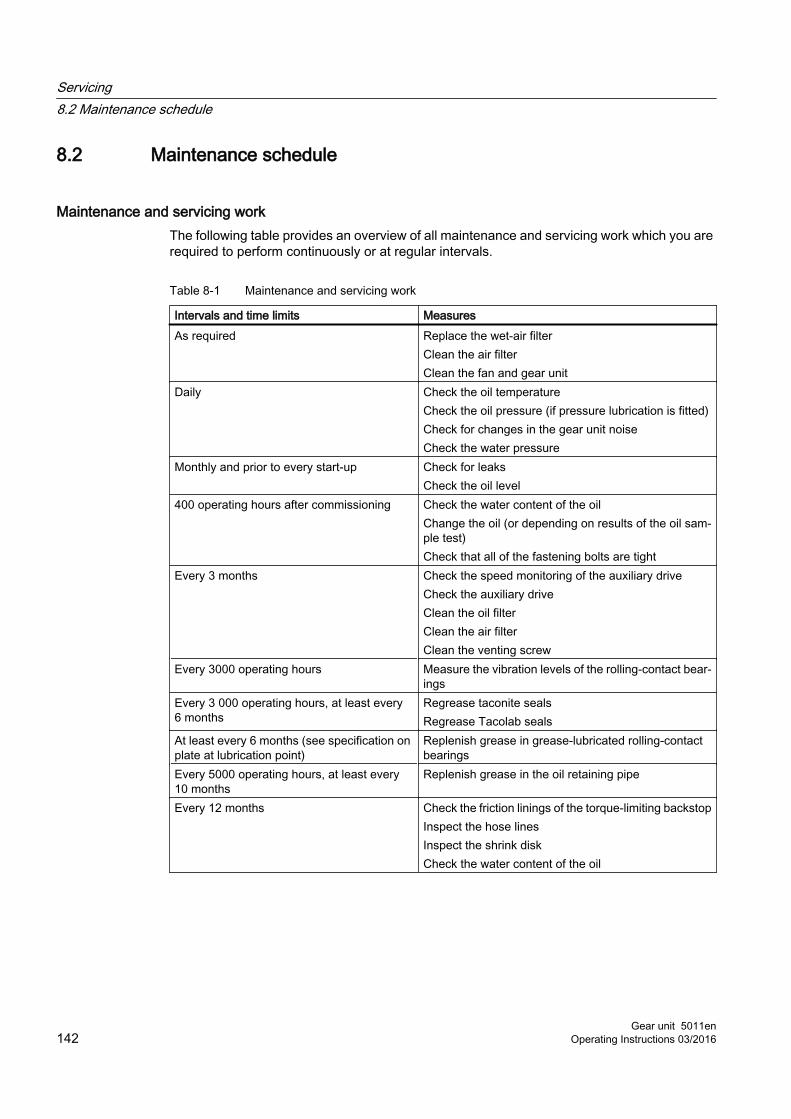
8.2 Maintenance schedule
Maintenance and servicing workThe following table provides an overview of all maintenance and servicing work which you are required to perform continuously or at regular intervals.
Table 8-1 Maintenance and servicing work
Intervals and time limits MeasuresAs required Replace the wet-air filter
Clean the air filterClean the fan and gear unit
Daily Check the oil temperatureCheck the oil pressure (if pressure lubrication is fitted)Check for changes in the gear unit noiseCheck the water pressure
Monthly and prior to every start-up Check for leaksCheck the oil level
400 operating hours after commissioning Check the water content of the oilChange the oil (or depending on results of the oil sam‐ple test)Check that all of the fastening bolts are tight
Every 3 months Check the speed monitoring of the auxiliary driveCheck the auxiliary driveClean the oil filterClean the air filterClean the venting screw
Every 3000 operating hours Measure the vibration levels of the rolling-contact bear‐ings
Every 3 000 operating hours, at least every 6 months
Regrease taconite sealsRegrease Tacolab seals
At least every 6 months (see specification on plate at lubrication point)
Replenish grease in grease-lubricated rolling-contact bearings
Every 5000 operating hours, at least every 10 months
Replenish grease in the oil retaining pipe
Every 12 months Check the friction linings of the torque-limiting backstopInspect the hose linesInspect the shrink diskCheck the water content of the oil
Servicing8.2 Maintenance schedule
Gear unit 5011en142 Operating Instructions 03/2016
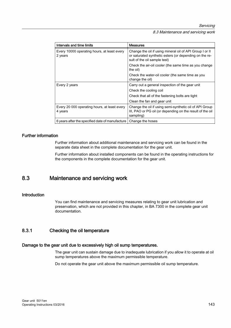
Intervals and time limits MeasuresEvery 10000 operating hours, at least every 2 years
Change the oil if using mineral oil of API Group I or II or saturated synthetic esters (or depending on the re‐sult of the oil sample test)Check the air‐oil cooler (the same time as you change the oil)Check the water‐oil cooler (the same time as you change the oil)
Every 2 years Carry out a general inspection of the gear unitCheck the cooling coilCheck that all of the fastening bolts are tightClean the fan and gear unit
Every 20 000 operating hours, at least every 4 years
Change the oil if using semi-synthetic oil of API Group III, PAO or PG oil (or depending on the result of the oil sampling)
6 years after the specified date of manufacture Change the hoses
Further informationFurther information about additional maintenance and servicing work can be found in the separate data sheet in the complete documentation for the gear unit.
Further information about installed components can be found in the operating instructions for the components in the complete documentation for the gear unit.
8.3 Maintenance and servicing work
IntroductionYou can find maintenance and servicing measures relating to gear unit lubrication and preservation, which are not provided in this chapter, in BA 7300 in the complete gear unit documentation.
8.3.1 Checking the oil temperature
Damage to the gear unit due to excessively high oil sump temperatures.The gear unit can sustain damage due to inadequate lubrication if you allow it to operate at oil sump temperatures above the maximum permissible temperature.
Do not operate the gear unit above the maximum permissible oil sump temperature.
Servicing8.3 Maintenance and servicing work
Gear unit 5011enOperating Instructions 03/2016 143

ProcedureProceed as follows to check the oil temperature:
1. Allow the gear unit to reach its normal operating temperature.
2. Operate the gear unit with the maximum driven machine power.
3. Measure the temperature of the oil in the oil sump.
4. Compare the measured value with the maximum permissible oil temperature (Page 139).
5. Immediately stop the gear unit if the maximum permissible oil temperature is exceeded. Contact Siemens Customer Services.
8.3.2 Filling the backstop with oil
Oil type and filling filterWhen filling the backstop with oil, observe the following points:
● Use the same oil type and oil viscosity as for the gear unit itself.
● Use a filling filter with the same filter mesh size as for the gear unit itself.
ProcedureProceed as follows to fill the backstop with oil:
1. Clean the oil filling point of the backstop.
2. Open the oil filling screw of the backstop.
3. Fill the amount of oil that is specified on the backstop plate. Use the same oil type and oil viscosity as for the gear unit itself.Use a filling filter with the same filter mesh size as for the gear unit itself.
4. Screw in the oil filling screw.
8.3.3 Filling the overrunning clutch of the auxiliary drive with oilProceed as follows to fill the overrunning clutch with oil:
1. Clean the oil filling point of the overrunning clutch.
2. Open the oil filling screw of the overrunning clutch.
3. Fill the amount of oil that is specified on the plate on the overrunning clutch. Use the same oil type and oil viscosity as for the gear unit itself.Use a filling filter with the same filter mesh size as the filter used to fill the gear unit.
4. Screw in the oil filling screw.
Servicing8.3 Maintenance and servicing work
Gear unit 5011en144 Operating Instructions 03/2016

8.3.4 Checking the auxiliary driveFollow the operating instructions of the auxiliary drive used that are included in the complete documentation for the gear unit.
8.3.5 Repacking grease in the oil retaining pipe
IntroductionOnly use grease that has been approved by Siemens AG as specified in BA 7300.
The precise designation of the grease nipple is provided in the complete documentation.
RequirementsUnder the following conditions, you must replenish the grease before commissioning the gear unit for the first time:
● Storage extending beyond 6 months
● Storage in a position other than the mounting position
ProcedureProceed as follows to replenish grease in an oil retaining pipe:
1. Clean the grease nipple.
2. Connect the lubrication device to the grease nipple.
3. Press in the specified quantity of lithium soap-based rolling-contact bearing grease. The lubrication points are marked by the following sign:
Figure 8-1 Sign: Lubrication point
4. Remove the lubrication device from the grease nipple.
CAUTION
Risk of slipping
There is a danger of slipping if the grease escapes from the oil retaining pipe.
Immediately remove any grease that has escaped from the oil retaining pipe and dispose of it correctly.
Servicing8.3 Maintenance and servicing work
Gear unit 5011enOperating Instructions 03/2016 145

8.3.6 Cleaning the fan and gear unit
IntroductionThe gear unit can sustain damage due to inadequate cooling if you operate it with a damaged or soiled fan. Depending on the conditions at the site of installation, it may therefore be necessary to clean the fan and gear unit more frequently than stipulated in the maintenance schedule.
Take appropriate measures to protect shaft seals from coming into contact with cleaning agents.
ProcedureProceed as follows to clean the fan and gear unit:
1. Remove the air guide cover.
2. Use a hard brush to remove any stubborn dirt from the impeller, air guide cover and protective grille. Never use a high-pressure cleaning device.
3. Treat any areas of corrosion.
4. Reinstall the air guide cover.Make sure that the air guide cover is correctly fastened. Make sure that there is no contact between the fan and the air guide cover.
8.3.7 Checking the cooling coil
IntroductionA soiled cooling coil can cause damage to the gear unit. It is therefore important to check the cooling coil regularly.
ProcedureTo check the cooling coil, proceed as follows:
1. Shut off the cooling water supply.
2. Disconnect the cooling water inlet and drain lines from the cooling coil.
Servicing8.3 Maintenance and servicing work
Gear unit 5011en146 Operating Instructions 03/2016

3. Inspect the inner surface of the cooling coil for deposits.
– If you discover that there are heavy deposits inside the cooling coil, arrange for the cooling water or the deposits to be analysed. Analysis services of this kind are offered by specialist chemical cleaning companies. These companies also sell special cleaning agents for removing deposits.
– Before you use a cleaning agent, check whether it is suitable for use on the cooling coil materials. You must consult Siemens Customer Services. Carefully read the instructions for use supplied by the manufacturer before using different kinds of cleaning agent.
– Replace especially severely soiled cooling coils by new ones. Please consult Siemens Customer Services (Page 155) for further advice.
4. Reconnect the cooling water inlet and drain lines to the cooling coil.
NOTICE
Build-up of heat due to soiled cooling coils
Overheating can damage the gear unit.
When the cooling coil is severely soiled, it can no longer be guaranteed to cool the gear unit effectively. In such cases, you must chemically clean the inside of the cooling coil or have it replaced with a new one.
8.3.8 Inspecting the shrink disk
IntroductionThe shrink disk inspection is limited to a visual assessment of its condition.
Aspects of the inspectionObserve the following points when inspecting the shrink disk:
● Loose bolts
● Damage due to use of force
● Inner ring resting flush against the outer ring
Further informationFurther information about the shrink disk can be found in the shrink disk operating instructions in the complete documentation for the gear unit.
Servicing8.3 Maintenance and servicing work
Gear unit 5011enOperating Instructions 03/2016 147

8.3.9 Cleaning the coarse filter
ProcedureTo clean the coarse filter, proceed as follows:
1. Inspect the coarse filter.
2. Remove the drain plug.
3. Pull out the strainer and remove particles of dirt.
4. Replace any strainers or sealing rings that are defective.
Further informationYou can find additional information about the coarse filter in the coarse filter operating instructions provided in the complete gear unit documentation.
You can find additional technical data in the separate data sheet and in the list of equipment provided in the complete gear unit documentation.
8.3.10 Cleaning the double change-over filter
ProcedureTo clean the double change-over filter, proceed as follows:
1. Inspect the double change-over filter.
2. Follow the operating instructions for the double change-over filter.
Further informationYou can find additional information about the double change-over filter in the double change-over filter operating instructions provided in the complete gear unit documentation.
You can find additional technical data in the separate data sheet and in the list of equipment provided in the complete gear unit documentation.
8.3.11 Checking the speed monitoring of the auxiliary drive
ProcedureProceed as follows to check the speed monitoring of the auxiliary drive:
1. Switch on the auxiliary drive.
2. Check whether the speed monitor switches.
Servicing8.3 Maintenance and servicing work
Gear unit 5011en148 Operating Instructions 03/2016

ResultIf the speed monitor does not switch, repair it or if necessary replace it.
Further informationYou can find additional information on the auxiliary drive in the auxiliary drive operating instructions, provided in the complete gear unit documentation.
8.3.12 Measuring the vibration levels of the rolling-contact bearings
ProcedureProceed as follows to measure the vibration levels of the rolling-contact bearings:
1. Measure the vibrations at the rolling-contact bearings.
2. Document the measurement results.
3. Compare the measured values with the comparison values that were documented when commissioning the gear unit.
4. Replace defective rolling-contact bearings.
5. Archive the report together with these instructions.
Further informationYou can find additional information on measuring the vibration levels at rolling-contact bearings in the operating instructions of the measurement sensor provided in the complete gear unit documentation.
8.3.13 Measuring the temperature at the rolling-contact bearings
ProcedureProceed as follows to measure the temperature at the rolling-contact bearings:
1. Measure the temperature at the rolling-contact bearings.
2. Document the measurement results.
3. Compare the measured values with the comparison values that were documented when commissioning the gear unit.
4. Archive the report together with these instructions.
5. Replace defective rolling-contact bearings.
Servicing8.3 Maintenance and servicing work
Gear unit 5011enOperating Instructions 03/2016 149

Further informationFurther information about measuring the temperature at the rolling-contact bearings can be found in the Pt 100 resistance thermometer operating instructions in the complete documentation for the gear unit.
8.3.14 Check that all of the fastening bolts are tightNote the following points when checking that the fastening bolts are tight:
● Observe the data regarding connection classes (Page 128), preload forces and tightening torques (Page 129).
● Replace any bolts that are no longer fit for use by bolts of the same strength class and type.
8.3.15 General inspection of the gear unitArrange for Siemens Customer Services to perform a general inspection on the gear unit. Thanks to their experience, these engineers are best placed to assess which gear unit components need to be replaced.
8.3.16 Final workAfter you have finished all the work listed in the maintenance schedule, replace any bolts that are no longer fit for use by bolts of the same strength class and type.
8.4 Possible faultsThe faults listed below are only intended as a troubleshooting guide.
If any faults occur while the unit is still under warranty, do not allow anyone except Siemens Customer Services to attempt a repair.
Even after the warranty period has expired, you should still arrange for faults to be rectified by Siemens Customer Services.
NoteLoss of warranty
You will invalidate the warranty for the gear unit if you modify it in any way without seeking the approval of Siemens beforehand, or if you do not use original spare parts.
Only use original spare parts from Siemens. Always arrange for Siemens Customer Services to repair any faults that develop while the unit is still under warranty.
Servicing8.4 Possible faults
Gear unit 5011en150 Operating Instructions 03/2016

Possible faults and their rectificationThe following table provides you with an overview of possible faults and indicates how they can be rectified.
Table 8-2 Possible faults and their rectification
Possible faults Causes Possible remediesBlocking function of backstop has failed
Damaged backstop ● Contact Customer Services● Check the backstop and replace if necessary
Pressure switch trig‐gers alarm
Oil pressure has dropped below minimum value
● Check the oil level at room temperature● Top up with oil if necessary● Check the oil pump● If required, replace the oil pump● Check the oil filter and coarse filter● If required, replace the oil filter or clean the coarse filter
Grease escaping at the output shaft
Defective rotary shaft sealing rings ● Inspect the rotary shaft seals and replace if necessary
Noise
Damage to the gear teeth ● Contact Customer Services● Inspect the toothed components● If necessary, replace damaged components
The bearing play is excessive. ● Contact Customer Services● Adjust bearing play
Defective rolling-contact bearings ● Contact Customer Services● Replace defective rolling-contact bearings
Overrunning noises caused by op‐eration on frequency converter
● Contact Customer Services● Check the closed-loop motor control system
Gear unit fastening has worked loose
● Tighten bolts and nuts to the specified tightening torque● Replace damaged bolts and nuts
Outer surface of gear unit soiled with oil
Inadequate sealing of the housing cover or joints
● Seal housing cover or joints
Labyrinth seals soiled with oil, incor‐rect transport position
● Check oil filling● Clean the labyrinths
Main drive motor does not start
Motor direction of rotation incorrect ● Change polarity of motorBackstop cage with sprags incor‐rectly installed or defective
● Contact Customer Services● Install the backstop cage, rotated through 180° - or replace
Overrunning clutch blocked ● Contact Customer Services● Install a new overrunning clutch
Overrunning clutch cage with sprags incorrectly installed and/or defective
● Contact Customer Services● Install the overrunning clutch cage, rotated through 180°
- or replace
Servicing8.4 Possible faults
Gear unit 5011enOperating Instructions 03/2016 151

Possible faults Causes Possible remediesMain drive motor can start while the auxiliary drive is operational
Defective electrical interlocking be‐tween the main and auxiliary motor
● Check the connections● If necessary, replace defective devices
Defective speed monitoring ● Check the connections● If necessary, replace defective devices
Auxiliary drive motor does not start
Overload at the output ● Reduce the load at the outputDefective auxiliary drive motor ● Repair or replace the motorMotor brake not released ● Correct the electrical connection of the motor brake
● If required, replace the motor brakeThe auxiliary drive mo‐tor starts, the main gear unit output shaft does not turn
Motor direction of rotation incorrect ● Change polarity of motorOverrunning clutch cage with sprags incorrectly installed
● Contact Customer Services● Install the overrunning clutch cage, rotated through 180°
- or replaceDefective overrunning clutch ● Contact Customer Services
● Install a new overrunning clutchLeakage
Labyrinth seals soiled with oil, incor‐rect transport position
● Check oil filling● Clean the labyrinths
Inadequate sealing of the housing cover or joints
● Check the seals and replace if necessary● Seal housing cover or joints
Defective rotary shaft sealing rings ● Check the rotary shaft sealing rings● Replace, if necessary
Wet-air filter is severe‐ly discoloured
Wet-air filter is spent ● Replace the wet-air filter
Wet-air filter is becom‐ing discoloured from the top downwards
Water in the oil ● Take test tube sample to examine oil condition for water penetration
● Have the oil examined by a chemical lab● Change the oil if necessary
Oil is foaming in the gear unit
Preservation agent not completely drained off
● Change the oil
Oil supply system left in operation for too long at low temperatures
● Switch off the oil supply system● Degas the oil
Gear unit too cold in operation ● Switch off the gear unit● Degas the oil● Start up without cooling water during cold restart
Water in the oil ● Take test tube sample to examine oil condition for water penetration
● Have the oil examined by a chemical lab● Change the oil if necessary
Oil defoamer has run out ● Examine the oil● Change the oil if necessary
Unsuitable mixture of oils ● Examine the oil● Change the oil if necessary
Servicing8.4 Possible faults
Gear unit 5011en152 Operating Instructions 03/2016

Possible faults Causes Possible remediesOil escaping from the gear unit
Inadequate sealing of the housing cover or joints
● Check the seals and replace if necessary● Seal housing cover or joints● Check the compression seals and retighten screws if
necessaryLeaking pipes ● Check the pipes, and replace or seal if necessary
Oil supply system mal‐function
- ● Follow the operating instructions for the oil supply system
Elevated temperature during operation
Oil level in the gear unit housing too high
● Check the oil level ● Correct the oil level if necessary
Oil is too old ● Find out when the last oil change was done● Change the oil if necessary
Oil is severely contaminated ● Change the oilOil supply system or cooling coil de‐fective
● Check the oil supply system or cooling coil● Replace defective components if necessary ● Follow the operating instructions for the oil supply system
Gear unit with water-oil cooler: Cool‐ant flow too low or too high
● Adjust the valves at the supply and return lines● Check the water-oil cooler for free flow
Gear unit with air-oil cooler: Inade‐quate air flow
● Clean the air-oil cooler
Gear unit with air-oil cooler: Cooler block soiled
● Clean the cooler block
Gear unit with oil cooling system: Inadequate oil flow through the oil cooler
● Check the oil filter and coarse filter● If required, replace the oil filter or clean the coarse filter
Gear units with cooling coil: Depos‐its in the cooling coil
● Clean, or if necessary, replace the cooling coil
Gear unit with fan: Air intake open‐ing in air guide cover or gear unit housing is soiled
● Clean the air guide cover and gear unit housing
Coolant temperature is too high ● Check the temperature; correct if necessaryDefective oil pump ● Check the oil pump function
● If required, repair or replace the oil pump
Servicing8.4 Possible faults
Gear unit 5011enOperating Instructions 03/2016 153

Possible faults Causes Possible remediesElevated temperature at bearing points
Oil level in the gear unit housing too low or too high
● Check the oil level at room temperature● Correct the oil level if necessary
Oil is too old ● Find out when the last oil change was done● Change the oil if necessary
Oil supply system defective ● Check the oil supply system● Replace defective components if necessary● Follow the operating instructions for the oil supply system
Defective rolling-contact bearings ● Contact Customer Services● Inspect the rolling-contact bearings and replace if
necessaryDefective oil pump ● Check the oil pump function
● If required, repair or replace the oil pumpElevated temperature at backstop
Damaged backstop ● Contact Customer Services● Check the backstop and replace if necessary
Increased vibration amplitude at the bear‐ing points
Defective rolling-contact bearings ● Contact Customer Services● Inspect the rolling-contact bearings and replace if
necessaryGear wheels defective ● Contact Customer Services
● Inspect the gear wheels and replace if necessaryContamination indica‐tor of the double change-over filter trig‐gers an alarm
Double change-over filter clogged ● Change over the double change-over filter corresponding to the separate operating instructions
● Clean the filter element
Water in the oil Oil supply system or cooling coil de‐fective
● Check the oil supply system or cooling coil● Replace defective components if necessary● Follow the operating instructions for the oil supply system
Engine room fan is blowing cold air onto gear unit: Water condenses
● Install suitable thermal insulation to protect gear unit housing
● Close the air outlet or change the direction of the air outlet using structural measures.
Climatic conditions ● Contact Customer Services● Use wet-air filter if necessary
Oil foams in the oil sump ● Take test tube sample to examine oil condition for water penetration
● Have the oil examined by a chemical lab
Servicing8.4 Possible faults
Gear unit 5011en154 Operating Instructions 03/2016

Service & Support 9Contact
When ordering spare parts, requesting a customer service technician or in the case of technical queries, please contact our factory or one of our customer service addresses:
Siemens Industriegetriebe GmbH
Thierbacher Strasse 24
09322 Penig
Germany
Tel.: +49 (0)37381 / 61-0
Fax: +49 (0)37381 / 80286
Gear unit 5011enOperating Instructions 03/2016 155

Service & Support
Gear unit 5011en156 Operating Instructions 03/2016

Disposal 10Disposal of the gear unit
When disposing of the gear unit after its useful life, please observe the following measures:
● Remove operating oil, preservative agents and coolant from the gear unit and dispose of it according to regulations.
● Dispose of the gear unit parts according to applicable national regulations or recycle them.
Environmental protectionObserve the following environmental protection measures for disposal:
● Dispose of or recycle packaging material according to applicable national regulations.
● When changing the oil, collect the used oil in suitable containers. Use oil-binding agents to clean up any oil spillages immediately.
● Store preservative agents separately from used oil.
● Dispose of used oil, preservative agents, oil binding agents and oil-soaked cloths according to the applicable environmental protection regulations.
Gear unit 5011enOperating Instructions 03/2016 157
Disposal
Gear unit 5011en158 Operating Instructions 03/2016

Spare parts 11By stocking the most important spare parts at the installation site you can ensure that the gear unit is ready for use at any time.
NoteDamage to the gear unit due to use of unsuitable spare parts
Only use original spare parts from Siemens. Siemens shall not accept any warranty claims for spare parts that are not supplied by Siemens.
Other spare parts are not tested and approved by Siemens. Non-approved spare parts may possibly change the design characteristics of the gear unit and thus impair its active or passive safety.
Siemens will accept no liability or warranty whatsoever for damage occurring as a result of the use of non-approved spare parts. The same applies to any accessories which were not supplied by Siemens.
The contact address of Siemens Customer Services can be found under Service & Support (Page 155).
Information required when ordering spare partsTo order spare parts, refer to the spare-parts list. Only use spare parts that are supplied by Siemens.
When ordering spare parts, please provide the following information:
● Order number with item
● Type and size
● Part number
● Quantity
Gear unit 5011enOperating Instructions 03/2016 159

Spare parts
Gear unit 5011en160 Operating Instructions 03/2016

Quality documents AA.1 Declaration of Incorporation
Gear unit 5011enOperating Instructions 03/2016 161

Declaration of incorporation
Company name and full address of the manufacturer:
Siemens Industriegetriebe GmbHThierbacher Straße 2409322 PenigDeutschland – Germany
Name and address of the person, authorised to compile the relevant technical documentation:
Jens KleinSiemens Industriegetriebe GmbHThierbacher Straße 2409322 PenigDeutschland – Germany
Description and identification of the partly completed machinery:
Gear unitH..V, B..VSizes 1 to 22for driving machines
The following "Essential health and safety requirements" are applied and are met:– Directive 2006/42/EC Official Journal L 157, 9.6.2006, pages 24-86, annex I.
1.1, 1.1.2, 1.1.3, 1.1.5; 1.2.6; 1.3.1 ‐ 1.3.4, 1.3.6 ‐ 1.3.8.1; 1.4.1, 1.4.2.1; 1.5.1, 1.5.2,1.5.4 ‐ 1.5.11, 1.5.13; 1.6.1, 1.6.2; 1.7.1 ‐ 1.7.2, 1.7.4 - 1.7.4.3
The special technical documents described in Annex VII part B have been prepared.The manufacturer undertakes, in response to a reasoned request by national authorities, totransmit in electronic form relevant information about the partly completed machinery.
The partly completed machinery must not be put into service until it has been established thatthe machinery into which the partly completed machinery is to be incorporated has beendeclared to be in conformity with the provisions of Directive 2006/42/EC, as appropriate.
Siemens Industriegetriebe GmbH
Penig, 2016‐03‐23 i.V.Jens Klein, Head of PD MD AP PNG
Penig, 2016‐03‐23 i.V.Tobias Bronsert, Head of PD MD AP PNG BA
Translation of the original declaration of incorporation
Quality documentsA.1 Declaration of Incorporation
Gear unit 5011en162 Operating Instructions 03/2016

Technical data BB.1 General technical data
Rating plateThe gear unit rating plate contains the most important technical data.
① Company logo ⑧ Speed n2
② Serial no.: production plant code/order no. item ser. no./year of manufacture
⑨ Oil data: Oil type, oil viscosity, oil quantity
③ Total weight in kg ⑩ Numbers of operating instructions④ For special information ⑪ For special information⑤ Type, size ⑫ Manufacturer and place of manufacture⑥ Power rating P2 in kW or torque T2 in Nm ⑬ Country of origin⑦ Speed n1
The limits of the intended use of the gear unit are defined on the basis of these data and the contractual agreements concerning the gear unit concluded between Siemens and the customer.
Further informationFurther information about these technical data can be found in the separate data sheet and the dimension drawings in the complete documentation for the gear unit.
Further information about all major accessories including their technical data and control instructions can be found in the order-specific list of equipment in the complete documentation for the gear unit.
Gear unit 5011enOperating Instructions 03/2016 163

Example codeThe following is an example of the code printed in line 5 of the rating plate and explains the meaning of the individual letters and numbers.
The following is an example of the code printed in line 5 of the rating plate and explains the meaning of the individual letters and numbers.
Further informationYou can find additional information on the weights and the enveloping surface sound pressure levels in chapters Weights (Page 168) and Enveloping surface sound pressure level (Page 173).
Technical dataB.1 General technical data
Gear unit 5011en164 Operating Instructions 03/2016

Further information about these technical data can be found in the separate data sheet and the dimension drawings in the complete documentation for the gear unit.
B.2 Ambient temperatureThe gear unit may be operated in an ambient temperature range from -20 °C to 40 °C. By applying various suitable measures, the gear unit can be used in the ambient temperature range extending from -40 °C up to 60 °C. However, this must always be authorised by Siemens and specified in the order text.
Storing the gear unitDo not expose the gear unit to harmful effects such as aggressive chemical products, environments with high levels of air pollution or humidity, or ambient temperatures below 0 °C or above 40 °C range.
B.3 TypesThe gear unit is available in the following types.
H.SV, H.VV B.SV, B.VV
H.HV, H.KV B.HV, B.KV
H.DV B.DV
H.FV B.FV
Technical dataB.3 Types
Gear unit 5011enOperating Instructions 03/2016 165
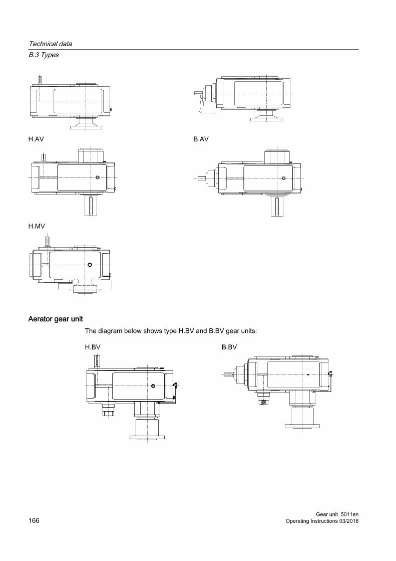
H.AV B.AV
H.MV
Aerator gear unitThe diagram below shows type H.BV and B.BV gear units:
H.BV B.BV
Technical dataB.3 Types
Gear unit 5011en166 Operating Instructions 03/2016

Agitator gear unitThe diagram below shows type H..V agitator gear units:
H.RV H.TV
H.GV H.JV
Water turbine gear unitThe diagram below shows type H.WV and B.WV water turbine gear units:
H.WV B.WV
Technical dataB.3 Types
Gear unit 5011enOperating Instructions 03/2016 167

Pulper gear unitThe diagram below shows a pulper gear unit:
B2PV
Further informationFurther information and a detailed illustrated description of the gear unit can be found in the dimension drawing in the complete documentation for the gear unit.
B.4 WeightsThe precise weights are specified in the dimension drawings in the complete documentation or on the rating plate.
All weight specifications refer to units without oil filling or mounted components.
Refer to the following tables for the weights (approximate values, in kg) of the helical and bevel helical gear units (Page 165):
Table B-1 Weights
Type Gear unit size1 2 3 4 5 6 7 8 9 10 11 12
H2.V - - 115 190 300 355 505 590 830 960 1 335 1 615H3.V - - - - 320 365 540 625 875 1 020 1 400 1 675H4.V - - - - - - 550 645 875 1 010 1 460 1 725B2.V 65 90 140 235 360 410 615 700 1 000 1 155 1 640 1 910B3.V - - 130 210 325 380 550 635 890 1 020 1 455 1 730B4.V - - - - 335 385 555 655 890 1 025 1 485 1 750
Technical dataB.4 Weights
Gear unit 5011en168 Operating Instructions 03/2016

Table B-2 Weights
Type Gear unit size13 14 15 16 17 18 19 20 21 22
H2.V 1 880 2 430 3 240 3 465 4 420 4 870 5 000 6 150 6 950 7 550H3.V 2 155 2 490 3 260 3 625 4 250 4 740 4 750 6 250 6 550 7 050H4.V 2 270 2 600 3 440 3 740 4 445 4 915 5 300 5 950 7 250 7 750B2.V 2 350 2 725 3 795 4 160 5 320 5 860 - - - -B3.V 2 260 2 615 3 540 3 765 4 760 5 240 6 050 6 710 8 190 8 950B4.V 2 280 2 605 3 435 3 765 4 460 4 930 5 400 6 000 7 350 7 850
Aerator gear unitRefer to the following table for the weights (approximate values, in kg) of the aerator gear units (Page 165):
Table B-3 Weights
Type Gear unit size5 6 7 8 9 10 11 12 13 14 15 16
H2BV 330 395 565 670 925 980 1 500 1 785 2 370 2 780 3 715 4 000H3BV 350 405 600 705 970 1 140 1 565 1 845 2 465 2 840 3 735 4 160B3BV 355 420 610 710 985 1 140 1 620 1 900 2 570 2 965 4 015 4 300
Agitator gear unitRefer to the following table for the weights (approximate values, in kg) of the agitator gear units (Page 165):
Table B-4 Weights
Type Gear unit size5 6 7 8 9 10 11 12 13 14 15 16 17 18
H2RV 380 480 710 840 1 100 1 240 1 630 1 980 2 360 2 830 3 780 4 130 5 350 5 950H2TV 380 470 680 790 1 010 1 160 1 530 1 840 2 100 2 910 3 800 4 050 4 990 5 500H2GV 360 455 610 770 1 020 1 180 1 555 1 865 2 115 2 680 3 550 3 915 4 940 5 450H2JV 360 455 610 770 1 020 1 180 1 555 1 865 2 115 2 680 3 555 3 915 4 940 5 450H2MV 360 455 610 770 1 020 1 180 1 555 1 865 2 115 2 680 3 550 3 915 4 940 5 450H3RV 400 490 750 870 1 140 1 300 1 690 2 040 2 640 2 890 3 800 4 290 5 180 5 820H3TV 400 480 720 820 1 060 1 220 1 600 1 900 2 380 2 970 3 820 4 210 4 820 5 370H3GV 380 465 645 805 1 065 1 240 1 620 1 925 2 390 2 740 3 570 4 075 4 770 5 320H3JV 380 465 645 805 1 065 1 240 1 620 1 925 2 390 2 740 3 570 4 075 4 770 5 320H3MV 380 465 645 805 1 065 1 240 1 620 1 925 2 390 2 740 3 570 4 075 4 770 5 320H4RV - - 760 890 1 140 1 300 1 750 2 090 2 750 3 000 3 980 4 410 5 380 6 000H4TV - - 730 840 1 060 1 210 1 660 1 950 2 490 3 080 4 000 4 330 5 020 5 550H4GV - - 655 825 1 065 1 230 1 680 1 975 2 505 2 850 3 750 4 190 4 965 5 495
Technical dataB.4 Weights
Gear unit 5011enOperating Instructions 03/2016 169

Type Gear unit size5 6 7 8 9 10 11 12 13 14 15 16 17 18
H4JV - - 655 825 1 065 1 230 1 660 1 975 2 505 2 850 3 750 4 190 4 965 5 495H4MV - - 655 825 1 065 1 230 1 660 1 975 2 505 2 850 3 750 4 190 4 965 5 495
Water turbine gear unitRefer to the following tables for the weights (approximate values, in kg) of the water turbine gear units (Page 165):
Table B-5 Weights
Type Gear unit size5 6 7 8 9 10 11 12 13
H2WV 400 500 660 750 1 050 1 200 1 600 2 000 2 600B2WV 405 470 660 760 1 000 1 200 1 600 2 000 2 600
Table B-6 Weights
Type Gear unit size14 15 16 17 18 19 20 21 22
H2WV 3 000 4 100 4 700 5 550 6 400 7 500 9 200 10 400 12 000B2WV 3 050 4 000 4 690 5 700 6 600 - - - -
Pulper gear unitRefer to the following table for the weights (approximate values, in kg) of the pulper gear units (Page 165):
Table B-7 Weights
Type Gear unit size8 9 10 11 12 13 14 15 16 17 18
B2PV 850 1 170 1 360 1 950 2 330 2 800 3 250 4 400 5 100 6 450 7 300
B.5 Oil quantitiesThe oil quantity required is specified on the rating plate attached to the gear unit.
Technical dataB.5 Oil quantities
Gear unit 5011en170 Operating Instructions 03/2016

Refer to the following table for the oil quantities (approximate values, in litres) for a gear unit in vertical mounting position with splash lubrication (gear unit with oil expansion unit).
Table B-8 Oil quantities
Type Gear unit size1 2 3 4 5 6 7 8 9 10 11 12
H2SV, H2HV, H2DV - - 14 23 35 37 62 69 98 110 160 180H3SV, H3HV, H3DV - - - - 36 40 64 70 110 120 190 205H4SV, H4HV, H4DV - - - - - - 60 65 105 110 175 200B2SV, B2HV, B2DV 5 9.5 11.5 23.5 38 46 74 81 115 120 190 225B3SV, B3HV, B3DV - - 14 20 34 36 60 68 96 105 155 175B4SV, B4HV, B4DV - - - - 36 40 65 73 105 110 175 200
The oil quantities for gear unit sizes ≥ 13 are available on request.
Refer to the following table for the oil quantities (approximate values, in litres) for a gear unit in vertical mounting position with pressure lubrication.
Table B-9 Oil quantities
Type Gear unit size5 6 7 8 9 10 11 12 13 14 15 16 17 18
H2SV, H2HV, H2DV 17.5 18.5 31 35 49 55 80 90 120 135 185 200 265 285H3SV, H3HV, H3DV 24 27 42 47 73 80 110 120 160 180 225 260 325 335H4SV, H4HV, H4DV - - 44 48 78 81 113 129 140 160 220 230 280 300B2SV, B2HV, B2DV 19 23 37 40 57 60 95 114 125 140 190 200 270 295B3SV, B3HV, B3DV 17 18 30 34 48 52 77 87 115 130 180 190 260 275B4SV, B4HV, B4DV 18 20 32 36 52 55 87 100 135 150 210 220 270 285
The oil quantities for gear unit sizes ≥ 19 are available on request.
Aerator gear unitRefer to the following table for the oil quantities (approximate values, in litres) for an aerator gear unit in vertical mounting position with pressure lubrication.
Table B-10 Oil quantities
Type Gear unit size5 6 7 8 9 10 11 12 13 14 15 16
H2BV 14 15 25 28 40 44 64 72 95 110 160 180H3BV 12.5 14 22 24 38 42 66 72 85 105 130 160B3BV 14 15 27 30 39 42 62 71 96 105 150 155
Technical dataB.5 Oil quantities
Gear unit 5011enOperating Instructions 03/2016 171

Agitator gear unitRefer to the following table for the oil quantities (approximate values, in litres) for an agitator gear unit in vertical mounting position with splash lubrication (gear unit with oil expansion unit).
Table B-11 Oil quantities
Type Gear unit size5 6 7 8 9 10 11 12
H2RV, H2TV 35 37 62 69 98 110 160 180H2GV, H2JV 23 27 58 62 100 110 160 180H3RV, H3TV 36 40 64 70 110 120 190 205H3GV, H3JV 35 37 60 72 100 110 170 190H4RV, H4TV - - 60 65 105 110 175 200H4GV, H4JV - - 50 60 95 110 165 180
The oil quantities for gear unit sizes ≥ 13 are available on request.
Refer to the following table for the oil quantities (approximate values, in litres) for an agitator gear unit in vertical mounting position with pressure lubrication.
Table B-12 Oil quantities
Type Gear unit size7 8 9 10 11 12 13 14 15 16 17 18
H2RV, H2TV 31 35 49 55 80 90 120 135 185 200 265 285H2GV, H2JV 22 25 42 46 60 70 80 90 140 150 175 185H3RV, H3TV 44 49 75 83 113 123 160 180 225 260 325 335H3GV, H3JV 25 30 40 45 66 75 115 126 180 190 190 200H4RV, H4TV 37 40 64 67 106 122 115 125 170 180 220 230H4GV, H4JV 20 25 38 45 65 75 95 105 150 160 190 200
Water turbine gear unitRefer to the following tables for the oil quantities (approximate values, in litres) for a water turbine gear unit in vertical mounting position with pressure lubrication.
Table B-13 Oil quantities
Type Gear unit size5 6 7 8 9 10 11 12 13
H2WV 14 17 25 28 40 44 64 72 100B2WV 19 26 37 40 59 60 95 110 125
Technical dataB.5 Oil quantities
Gear unit 5011en172 Operating Instructions 03/2016

Table B-14 Oil quantities
Type Gear unit size14 15 16 17 18 19 20 21 22
H2WV 110 150 165 215 240 - - - -B2WV 140 190 210 250 280 - - - -
Pulper gear unitRefer to the following table for the oil quantities (approximate values, in litres) for a pulper gear unit in vertical mounting position with pressure lubrication.
Table B-15 Oil quantities
Type Gear unit size8 9 10 11 12 13 14 15 16 17 18
B2PV 28 42 45 75 80 95 100 130 130 185 185
B.6 Enveloping surface sound pressure levelThe gear unit has an enveloping surface sound pressure level at a distance of 1 m away, which can be taken from the following table.
The measurement is performed using the sound-intensity method according to DIN EN ISO 9614 Part 2.
The workplace of operating personnel is defined as the area on the measuring surface at a distance of 1 m around the gear unit and in the vicinity where persons may be present.
The sound pressure level applies to a gear unit in the warm condition at a drive speed n1 and output power P2 according to the rating plate, for measurements carried out on a Siemens test bench. If several values are given, then the highest speed and power values apply.
The enveloping surface sound pressure level includes any mounted lubrication units. With outgoing and incoming pipes, the flange is considered to be the interface.
The sound pressure levels listed in the table were obtained based on statistical evaluations carried out by our Quality Control department. With statistical certainty, it can be assumed that the gear unit complies with these sound pressure levels.
Technical dataB.6 Enveloping surface sound pressure level
Gear unit 5011enOperating Instructions 03/2016 173

Refer to the following tables for the enveloping surface sound pressure level LpA in dB(A) for bevel helical gear units with fan.
Table B-16 Enveloping surface sound pressure level
Type iN n1 in rpm Gear unit size1 2 3 4 5 6 7 8 9 10 11 12
B2 5 - 8 3000 79 83 85 89 - - - - - - - -1500 65 70 73 76 79 81 83 84 85 87 88 891000 <60 <60 67 71 73 74 77 78 79 80 82 83750 <60 <60 61 64 66 67 70 71 72 73 75 76
9 - 14 3000 79 81 83 87 89 90 - - - - - -1500 65 67 70 73 75 76 78 81 82 83 84 851000 <60 61 63 67 68 70 73 74 75 77 79 80750 <60 <60 <60 61 62 64 66 67 68 70 72 73
16 - 22.4
3000 77 79 81 85 88 89 90 91 92 - - -1500 63 65 67 71 74 76 78 79 80 81 83 841000 <60 <60 60 64 67 68 70 72 73 74 78 79750 <60 <60 <60 <60 61 63 65 67 68 69 71 72
B3 12.5 - 31.5
3000 - - 82 86 87 88 90 92 93 - - -1500 - - 69 72 75 77 79 80 81 82 83 851000 - - 62 65 68 69 71 72 73 74 77 78750 - - <60 <60 63 64 66 68 69 70 71 73
35.5 - 56
3000 - - 81 83 85 86 87 88 90 92 95 961500 - - 67 69 72 73 74 75 77 79 82 841000 - - <60 63 65 66 67 69 71 72 73 75750 - - <60 <60 <60 <60 62 64 65 67 69 70
63 - 90
3000 - - 80 82 84 85 87 88 90 92 94 951500 - - 66 68 70 71 73 74 76 78 81 831000 - - <60 61 63 64 66 68 69 71 73 75750 - - <60 <60 <60 <60 61 63 64 66 67 68
Technical dataB.6 Enveloping surface sound pressure level
Gear unit 5011en174 Operating Instructions 03/2016

Table B-17 Enveloping surface sound pressure level
Type iN n1 in rpm Gear unit size13 14 15 16 17 18 19 20 21 22
B2 5 - 8 3000 - - - - - - - - - -1500 91 92 94 - - - - - - -1000 84 85 87 89 90 - - - - -750 77 78 81 82 83 85 - - - -
9 - 14 3000 - - - - - - - - - -1500 86 87 88 90 - - - - - -1000 81 82 83 84 86 87 - - - -750 74 75 77 78 79 80 - - - -
16 - 22.4
3000 - - - - - - - - - -1500 87 88 89 90 - - - - - -1000 80 81 82 83 84 84 - - - -750 73 73 74 74 75 76 - - - -
B3 12.5 - 31.5
3000 - - - - - - - - - -1500 88 89 90 91 93 93 93 93 95 951000 80 82 83 83 84 85 86 86 88 88750 74 75 76 77 78 78 79 79 81 81
35.5 - 56
3000 - - - - - - - - - -1500 86 87 88 89 90 91 92 92 93 931000 77 78 79 80 81 82 83 84 85 86750 71 72 73 74 75 76 77 78 79 79
63 - 90
3000 - - - - - - - - - -1500 85 86 87 88 89 90 91 91 92 921000 77 78 79 80 81 81 82 82 83 84750 70 71 72 73 74 75 75 76 77 77
Technical dataB.6 Enveloping surface sound pressure level
Gear unit 5011enOperating Instructions 03/2016 175

Refer to the following tables for the enveloping surface sound pressure level LpA in dB(A) for bevel helical gear units without fan.
Table B-18 Enveloping surface sound pressure level
Type iN n1 in rpm Gear unit size1 2 3 4 5 6 7 8 9 10 11 12
B2 5 - 8 3000 75 81 84 88 - - - - - - - -1500 63 69 72 75 78 80 82 83 84 86 87 881000 <60 <60 66 70 72 73 76 77 78 79 81 82750 <60 <60 <60 63 65 66 69 71 72 73 74 75
9 - 14 3000 73 77 80 83 86 87 - - - - - -1500 61 64 67 71 74 75 77 79 80 81 83 841000 <60 <60 61 65 67 69 72 73 74 76 77 78750 <60 <60 <60 <60 60 63 65 66 67 69 71 72
16 - 22.4
3000 69 72 76 79 81 83 85 86 87 - - -1500 <60 60 63 66 69 71 72 74 75 77 78 801000 <60 <60 <60 61 63 65 67 68 69 71 72 74750 <60 <60 <60 <60 <60 <60 60 62 63 64 66 67
B3 12.5 - 31.5
3000 - - 77 81 84 86 87 88 90 - - -1500 - - 65 68 71 74 75 76 77 79 81 831000 - - <60 63 66 68 69 70 72 73 75 77750 - - <60 <60 <60 61 62 64 65 66 68 71
35.5 - 56
3000 - - 72 77 80 82 83 84 84 86 89 921500 - - 60 65 67 70 71 71 72 74 77 791000 - - <60 <60 62 65 65 66 66 69 71 73750 - - <60 <60 <60 <60 <60 <60 <60 62 65 67
63 - 90
3000 - - 69 73 76 84 80 80 81 83 84 881500 - - <60 61 64 70 67 68 68 70 73 751000 - - <60 <60 <60 63 62 62 62 65 68 70750 - - <60 <60 <60 <60 <60 <60 <60 <60 61 63
B4 80 - 125
3000 - - - - 76 77 79 81 82 85 87 891500 - - - - 64 65 67 68 70 72 75 761000 - - - - <60 <60 61 63 64 67 69 70750 - - - - <60 <60 <60 <60 <60 <60 62 64
140 - 224
3000 - - - - 72 74 76 77 78 81 84 851500 - - - - 60 61 63 65 66 68 71 721000 - - - - <60 <60 <60 <60 61 63 65 67750 - - - - <60 <60 <60 <60 <60 <60 <60 <60
250 - 400
3000 - - - - 69 70 72 74 75 77 80 811500 - - - - <60 <60 <60 62 63 65 67 691000 - - - - <60 <60 <60 <60 <60 <60 62 63750 - - - - <60 <60 <60 <60 <60 <60 <60 <60
Technical dataB.6 Enveloping surface sound pressure level
Gear unit 5011en176 Operating Instructions 03/2016

Table B-19 Enveloping surface sound pressure level
Type iN n1 in rpm Gear unit size13 14 15 16 17 18 19 20 21 22
B2 5 - 8 3000 - - - - - - - - - -1500 89 90 93 - - - - - - -1000 83 84 86 88 89 - - - - -750 77 78 80 82 83 84 - - - -
9 - 14 3000 - - - - - - - - - -1500 85 86 87 89 - - - - - -1000 80 81 82 83 85 86 - - - -750 73 74 76 77 78 79 - - - -
16 - 22.4
3000 - - - - - - - - - -1500 81 82 85 85 - - - - - -1000 75 77 79 80 81 81 - - - -750 68 70 72 73 74 75 - - - -
B3 12.5 - 31.5
3000 - - - - - - - - - -1500 84 85 86 87 87 88 89 90 91 921000 78 80 80 81 82 82 84 85 86 86750 71 73 73 74 75 75 77 78 79 79
35.5 - 56
3000 - - - - - - - - - -1500 80 81 82 83 83 84 86 86 88 881000 75 76 76 77 77 78 80 81 82 83750 68 69 70 70 71 72 74 74 75 76
63 - 90
3000 89 90 - - - - - - - -1500 76 78 78 79 79 80 82 83 84 841000 71 72 73 73 74 75 76 77 78 79750 64 65 66 67 67 68 70 70 72 72
B4 80 - 125
3000 90 91 92 - - - - - - -1500 77 79 80 81 82 83 84 85 86 861000 72 73 74 75 76 77 78 79 80 80750 65 66 68 68 69 71 71 72 73 74
140 - 224
3000 86 87 89 89 90 92 - - - -1500 73 75 76 77 78 79 80 81 82 821000 68 69 71 71 72 74 75 75 76 77750 61 62 64 65 66 67 68 69 69 70
250 - 400
3000 82 84 85 86 87 88 89 90 91 -1500 70 71 73 73 75 76 77 77 78 791000 64 66 67 68 69 70 71 72 73 73750 <60 <60 <60 61 62 63 64 65 66 66
Technical dataB.6 Enveloping surface sound pressure level
Gear unit 5011enOperating Instructions 03/2016 177

Refer to the following tables for the enveloping surface sound pressure level LpA in dB(A) for helical gear units with fan.
Table B-20 Enveloping surface sound pressure level
Type iN n1 in rpm Gear unit size1 2 3 4 5 6 7 8 9 10 11 12
H2 6.3 - 10
3000 - - - 85 87 - - - - - - -1500 - - - 75 76 77 80 81 82 84 85 861000 - - - 69 71 72 74 75 77 79 80 81750 - - - 66 68 69 70 72 73 75 76 77
11.2 - 16
3000 - - - 84 86 87 91 - - - - -1500 - - - 73 75 77 79 80 81 82 85 881000 - - - 68 69 70 72 73 75 77 79 80750 - - - 64 66 67 69 70 71 73 74 76
18 - 28
3000 - - - 83 84 85 88 90 92 - - -1500 - - - 71 73 75 77 78 80 82 84 861000 - - - 65 67 68 71 72 73 75 77 78750 - - - 62 64 65 67 68 69 71 73 74
H3 22.4 - 35.5
3000 - - - - 84 84 87 87 90 - - -1500 - - - - 71 72 75 75 77 77 80 801000 - - - - 65 66 69 70 71 72 74 75750 - - - - 62 62 66 67 67 68 70 70
40 - 63
3000 - - - - 84 84 86 86 89 89 92 931500 - - - - 70 71 73 74 76 76 79 791000 - - - - 64 65 67 68 69 70 73 73750 - - - - 62 62 63 64 65 66 69 69
71 - 112
3000 - - - - 83 83 85 85 89 89 92 921500 - - - - 70 70 72 72 75 75 78 781000 - - - - 64 64 65 66 68 69 71 72750 - - - - 61 61 62 62 64 65 67 67
Technical dataB.6 Enveloping surface sound pressure level
Gear unit 5011en178 Operating Instructions 03/2016

Table B-21 Enveloping surface sound pressure level
Type iN n1 in rpm Gear unit size13 14 15 16 17 18 19 20 21 22
H2 6.3 - 10
3000 - - - - - - - - - -1500 88 90 92 94 96 96 - - - -1000 83 84 85 86 87 88 88 89 90 -750 79 80 81 82 83 83 84 84 85 85
11.2 - 16
3000 - - - - - - - - - -1500 90 91 92 93 95 95 - - - -1000 82 83 84 85 85 86 86 87 87 87750 78 79 79 80 81 81 82 82 83 83
18 - 28
3000 - - - - - - - - - -1500 87 90 91 92 93 94 94 95 95 951000 80 81 82 83 83 84 85 85 86 86750 75 77 78 79 79 80 80 81 81 81
H3 22.4 - 35.5
3000 - - - - - - - - - -1500 81 81 84 84 84 85 - - - -1000 75 75 78 78 78 79 - - - -750 71 72 74 74 75 76 - - - -
40 - 63
3000 - - - - - - - - - -1500 80 80 83 82 83 83 - - - -1000 73 74 77 77 77 77 - - - -750 69 70 72 73 73 73 - - - -
71 - 112
3000 92 92 - - - - - - - -1500 78 78 82 82 82 82 - - - -1000 72 72 75 75 75 76 - - - -750 68 68 71 71 71 72 - - - -
Refer to the following tables for the enveloping surface sound pressure level LpA in dB(A) for helical gear units without fan.
Table B-22 Enveloping surface sound pressure level
Type iN n1 in rpm Gear unit size1 2 3 4 5 6 7 8 9 10 11 12
H2 6.3 - 10
1500 - - - 71 74 75 76 77 79 79 80 811000 - - - 66 69 70 71 72 74 74 75 76750 - - - 63 66 67 67 69 70 71 72 73
11.2 - 16
1500 - - - 69 72 73 74 75 77 77 78 791000 - - - 64 67 68 69 70 72 72 73 74750 - - - 61 64 65 66 67 69 69 70 71
18 - 28
1500 - - - 66 69 70 71 72 74 74 75 761000 - - - 61 64 65 66 68 69 69 70 71750 - - - <60 61 62 63 64 66 66 67 68
Technical dataB.6 Enveloping surface sound pressure level
Gear unit 5011enOperating Instructions 03/2016 179
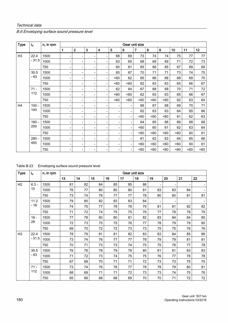
Type iN n1 in rpm Gear unit size1 2 3 4 5 6 7 8 9 10 11 12
H3 22.4 - 31.5
1500 - - - - 68 69 73 74 74 75 77 771000 - - - - 63 65 68 69 69 71 72 73750 - - - - 60 61 65 66 65 67 69 69
35.5 - 63
1500 - - - - 65 67 70 71 71 73 74 751000 - - - - <60 62 65 66 66 68 69 70750 - - - - <60 <60 62 63 63 65 66 67
71 - 112
1500 - - - - 62 64 67 68 68 70 71 721000 - - - - <60 <60 62 63 63 65 66 67750 - - - - <60 <60 <60 <60 <60 62 63 64
H4 100 - 140
1500 - - - - - - 66 67 68 69 70 711000 - - - - - - 62 63 63 64 65 66750 - - - - - - <60 <60 <60 61 62 63
160 - 250
1500 - - - - - - 64 65 66 66 68 681000 - - - - - - <60 60 61 62 63 64750 - - - - - - <60 <60 <60 <60 60 61
280 - 450
1500 - - - - - - 61 62 63 64 65 661000 - - - - - - <60 <60 <60 <60 60 61750 - - - - - - <60 <60 <60 <60 <60 <60
Table B-23 Enveloping surface sound pressure level
Type iN n1 in rpm Gear unit size13 14 15 16 17 18 19 20 21 22
H2 6.3 - 10
1500 81 82 84 85 85 86 - - - -1000 76 77 80 80 80 81 83 83 84 -750 73 74 76 77 77 78 80 80 81 81
11.2 - 16
1500 79 80 82 83 83 84 - - - -1000 74 75 77 78 78 79 81 81 82 82750 71 72 74 75 75 76 77 78 79 79
18 - 28
1500 77 78 80 80 81 82 83 84 84 851000 72 73 75 75 76 77 78 79 79 80750 69 70 72 72 73 73 75 75 76 76
H3 22.4 - 31.5
1500 78 79 81 81 82 83 83 84 85 861000 73 74 76 77 77 78 79 79 81 81750 70 71 73 73 74 75 75 76 77 78
35.5 - 63
1500 76 76 78 79 79 80 81 81 83 831000 71 72 73 74 75 75 76 77 78 78750 67 68 70 71 71 72 73 73 75 75
71 - 112
1500 73 74 76 76 77 78 78 79 80 811000 68 69 71 71 72 73 73 74 75 76750 65 66 68 68 69 70 70 71 72 72
Technical dataB.6 Enveloping surface sound pressure level
Gear unit 5011en180 Operating Instructions 03/2016

Type iN n1 in rpm Gear unit size13 14 15 16 17 18 19 20 21 22
H4 100 - 140
1500 72 73 75 75 76 76 77 78 78 781000 67 68 70 70 71 72 72 73 73 74750 64 64 66 67 68 68 69 69 70 70
160 - 250
1500 69 70 72 73 73 74 74 75 75 761000 64 65 67 68 68 69 70 70 71 71750 61 62 64 64 65 66 66 67 67 68
280 - 450
1500 67 67 69 70 70 71 72 72 73 731000 62 63 64 65 66 66 67 68 68 68750 <60 <60 61 62 62 63 64 64 65 65
Technical dataB.6 Enveloping surface sound pressure level
Gear unit 5011enOperating Instructions 03/2016 181

Technical dataB.6 Enveloping surface sound pressure level
Gear unit 5011en182 Operating Instructions 03/2016

Glossary
CAVEXCAVEX is an assembly and sales company for worm gear sets, worm gear units and drive solutions.
CSFWType of CAVEX helical worm unit, where the flange is defined as the output.
DU bushingDesignation for a type of plain bearing.
EDDuty cycle
HPGHigh Precision Gears
MIL-spec connectorAn MIL-spec connector is a circular connector used for military, aeronautic and industrial applications.
PAOPoly-alpha-olefin is a synthetic paraffin and naphthenic base oil.
PG/PAGPolyglycol is a synthetic, common water soluble polymer-based base oil.
ZAPEX couplingA ZAPEX coupling is a torsionally rigid gear coupling manufactured by Siemens AG.
Gear unit 5011enOperating Instructions 03/2016 183

Glossary
Gear unit 5011en184 Operating Instructions 03/2016

Index
AAerator gear unit, 30, 166Agitator gear unit, 25, 31, 167Air guide cover, 47Air-oil cooler, 51, 52Attachment points, 79Auxiliary drive
Checking, 145Checking the speed monitoring, 148Commissioning, 134Filling the overrunning clutch with oil, 144
BBackstop, 47
Commissioning, 134filling with oil, 144Principle of operation, 46
Bearing monitoringAcceleration sensor, 62Connecting, 126Resistance thermometer, 61Shock-pulse transducer, 61
CCentrifugal disk, 45Coarse filter
Cleaning, 148Coloured markings, 16Contact, 155Cooling, 47Cooling coil
Commissioning, 135Cooling water flow rate, 50Design, 50Principle of operation, 48
Copyright, 14Coupling, 56Customer Services, 155
DDanger of explosion, 20Directions of rotation, 23
Disclaimer, 13Disposal, 157Documentation landscape, 14Double change-over filter
Cleaning, 148
EEnvironmental protection, 157Equipment features, 26Eye bolts, 71
FFan, 47Fastening bolts
Bolt connection class, 128Bolts, 127Checking for tightness, 150Mating threads, 128Preload force, 129Tightening procedure, 128Tightening torque, 129
Fault, 150Fault rectification, 151Final work, 130Flange pump, 39
GGear unit designs, 23Gear unit equipment, 27Gear unit housing, 26Gear unit markings, 16General inspection of the gear unit, 150Grease nipple, 145
HHeating
Commissioning, 136Design, 58Function, 57Heating elements, 57Temperature monitor, 58
Gear unit 5011enOperating Instructions 03/2016 185

IInterval, 142Irregularities in operation, 139
LLabyrinth seal, 41Lateral pulling, 71Lubricant, 14Lubrication point, 26
MMaintenance activities, 142Maintenance information, 141Maintenance schedule, 142Measures
during commissioning, 137Prior to commissioning, 133
Motor pump, 38Mounting position, 79
NNote about assembly, 79
OOil, 14Oil expansion unit, 36Oil filter, 40, 55Oil level indicator, 59Oil retaining pipe, 45
Repacking grease, 145Oil supply, 36Oil supply system, 37, 51, 52, 53, 54, 55
Commissioning, 136Flange pump, 39Motor pump, 38
Oil supply variants, 36Oil temperature
Checking, 144Oil temperature monitoring, 60Operating data
Compliance with, 139Oil, 139
Ordering spare parts, 155, 159Output shaft versions, 24
PPreservation
Interior preservation through oil filling, 77Pressure lubrication, 36, 37Protective equipment, 18Pulper gear unit, 34, 168Pump, 40, 55
RRating plate, 163
Example of type and size, 164Reactivating, 22Resistance thermometer, 60
Connecting, 125Rolling-contact bearings
Grease filling, 74Measure temperature, 149Measuring the vibration levels, 149
Rotary shaft sealing ring, 41
SSafety rules, 15Scope of delivery, 69Servicing activities, 142Shaft bearings, 40Shaft seal, 40Shaft-mounted gear unit
Assembly, 99, 106, 113Auxiliary plate, 104Axial locking, 102Dismantling, 102End plate, 103, 104Hydraulic pulling equipment, 104
Shear pulling, 71Shipping documents, 69Shrink disk
Checking, 147Splash lubrication, 36
TTaconite seal, 42Taking the unit out of service, 140Technical data, 163Temperature monitor
Connecting, 125
Index
Gear unit 5011en186 Operating Instructions 03/2016

Transport information, 69Transport symbols, 70Troubleshooting, 150Types of danger, 18
UUnpacking, 80Used oil, 157Using the gear unit, 21
WWarning symbols, 17Water turbine gear unit, 33, 167Water-oil cooler, 53, 54
Index
Gear unit 5011enOperating Instructions 03/2016 187

Index
Gear unit 5011en188 Operating Instructions 03/2016

AA 5011_en_EBE

Siemens AGProcess Industries and DrivesPostfach 48 4890026 NÜRNBERGGERMANY
www.siemens.com/drives