FlashStack for SAP HANA TDI PDF - Cisco · SAP HANA is SAP SE’s implementation of in-memory...
282
FlashStack for SAP HANA TDI Last Updated: December 10, 2018
Transcript of FlashStack for SAP HANA TDI PDF - Cisco · SAP HANA is SAP SE’s implementation of in-memory...
FlashStack for SAP HANA TDI Last Updated: December 10, 2018
2
About the Cisco Validated Design Program
The Cisco Validated Design (CVD) program consists of systems and solutions designed, tested, and documented
to facilitate faster, more reliable, and more predictable customer deployments. For more information, see:
http://www.cisco.com/go/designzone.
ALL DESIGNS, SPECIFICATIONS, STATEMENTS, INFORMATION, AND RECOMMENDATIONS (COLLECTIVELY,
"DESIGNS") IN THIS MANUAL ARE PRESENTED "AS IS," WITH ALL FAULTS. CISCO AND ITS SUPPLIERS
DISCLAIM ALL WARRANTIES, INCLUDING, WITHOUT LIMITATION, THE WARRANTY OF MERCHANTABILITY,
FITNESS FOR A PARTICULAR PURPOSE AND NONINFRINGEMENT OR ARISING FROM A COURSE OF DEALING,
USAGE, OR TRADE PRACTICE. IN NO EVENT SHALL CISCO OR ITS SUPPLIERS BE LIABLE FOR ANY INDIRECT,
SPECIAL, CONSEQUENTIAL, OR INCIDENTAL DAMAGES, INCLUDING, WITHOUT LIMITATION, LOST PROFITS
OR LOSS OR DAMAGE TO DATA ARISING OUT OF THE USE OR INABILITY TO USE THE DESIGNS, EVEN IF
CISCO OR ITS SUPPLIERS HAVE BEEN ADVISED OF THE POSSIBILITY OF SUCH DAMAGES.
THE DESIGNS ARE SUBJECT TO CHANGE WITHOUT NOTICE. USERS ARE SOLELY RESPONSIBLE FOR THEIR
APPLICATION OF THE DESIGNS. THE DESIGNS DO NOT CONSTITUTE THE TECHNICAL OR OTHER
PROFESSIONAL ADVICE OF CISCO, ITS SUPPLIERS OR PARTNERS. USERS SHOULD CONSULT THEIR OWN
TECHNICAL ADVISORS BEFORE IMPLEMENTING THE DESIGNS. RESULTS MAY VARY DEPENDING ON
FACTORS NOT TESTED BY CISCO.
CCDE, CCENT, Cisco Eos, Cisco Lumin, Cisco Nexus, Cisco StadiumVision, Cisco TelePresence, Cisco WebEx,
the Cisco logo, DCE, and Welcome to the Human Network are trademarks; Changing the Way We Work, Live,
Play, and Learn and Cisco Store are service marks; and Access Registrar, Aironet, AsyncOS, Bringing the Meeting
To You, Catalyst, CCDA, CCDP, CCIE, CCIP, CCNA, CCNP, CCSP, CCVP, Cisco, the Cisco Certified Internetwork
Expert logo, Cisco IOS, Cisco Press, Cisco Systems, Cisco Systems Capital, the Cisco Systems logo, Cisco
Unified Computing System (Cisco UCS), Cisco UCS B-Series Blade Servers, Cisco UCS C-Series Rack Servers,
Cisco UCS S-Series Storage Servers, Cisco UCS Manager, Cisco UCS Management Software, Cisco Unified
Fabric, Cisco Application Centric Infrastructure, Cisco Nexus 9000 Series, Cisco Nexus 7000 Series. Cisco Prime
Data Center Network Manager, Cisco NX-OS Software, Cisco MDS Series, Cisco Unity, Collaboration Without
Limitation, EtherFast, EtherSwitch, Event Center, Fast Step, Follow Me Browsing, FormShare, GigaDrive,
HomeLink, Internet Quotient, IOS, iPhone, iQuick Study, LightStream, Linksys, MediaTone, MeetingPlace,
MeetingPlace Chime Sound, MGX, Networkers, Networking Academy, Network Registrar, PCNow, PIX,
PowerPanels, ProConnect, ScriptShare, SenderBase, SMARTnet, Spectrum Expert, StackWise, The Fastest Way
to Increase Your Internet Quotient, TransPath, WebEx, and the WebEx logo are registered trademarks of Cisco
Systems, Inc. and/or its affiliates in the United States and certain other countries.
All other trademarks mentioned in this document or website are the property of their respective owners. The use
of the word partner does not imply a partnership relationship between Cisco and any other company. (0809R)
© 2018 Cisco Systems, Inc. All rights reserved.
3
Table of Contents
About the Cisco Validated Design Program .................................................................................................................................................... 2
Executive Summary ........................................................................................................................................................................................ 7
Solution Overview ........................................................................................................................................................................................... 8
Introduction ................................................................................................................................................................................................ 8
Audience .................................................................................................................................................................................................... 8
Goals and Objectives of this Document ...................................................................................................................................................... 8
FlashStack System Overview ..................................................................................................................................................................... 9
Design Principles ...................................................................................................................................................................................... 10
FlashStack Solution Benefits .................................................................................................................................................................... 10
Infrastructure Requirements for the SAP HANA Database ............................................................................................................................ 12
CPU .......................................................................................................................................................................................................... 12
Memory .................................................................................................................................................................................................... 12
CPU and Memory Combinations .............................................................................................................................................................. 12
Network .................................................................................................................................................................................................... 13
Storage..................................................................................................................................................................................................... 14
Filesystem Layout .................................................................................................................................................................................. 15
Operating System ..................................................................................................................................................................................... 16
High Availability ......................................................................................................................................................................................... 16
Technology Overview ................................................................................................................................................................................... 17
Cisco Unified Computing System ............................................................................................................................................................. 17
Cisco Unified Computing System Components ........................................................................................................................................ 18
Cisco UCS Manager ................................................................................................................................................................................. 19
Cisco UCS Service Profile ........................................................................................................................................................................ 20
Cisco UCS 6300 Unified Fabric Interconnects ......................................................................................................................................... 24
Cisco UCS 6300 Series Fabric Interconnect Models ............................................................................................................................ 25
Cisco UCS 2304XP Fabric Extender ..................................................................................................................................................... 26
Cisco UCS Blade Chassis ........................................................................................................................................................................ 26
Cisco UCS B480 M5 Blade Server .......................................................................................................................................................... 26
Cisco VIC Interface Card ....................................................................................................................................................................... 27
Cisco VIC 1380 Virtual Interface Card ................................................................................................................................................... 28
Cisco Nexus 9336C-FX2 Switches ......................................................................................................................................................... 28
Cisco MDS 9148S 16G FC Switches ....................................................................................................................................................... 29
Pure Storage FlashArray //X R2................................................................................................................................................................ 30
Purity Operating Environment ................................................................................................................................................................... 32
Purity//FA Pure1® ..................................................................................................................................................................................... 33
Experience Evergreen™ Storage .............................................................................................................................................................. 33
Solution Architecture ..................................................................................................................................................................................... 34
4
Physical Topology..................................................................................................................................................................................... 34
Considerations ....................................................................................................................................................................................... 35
Solution components and Software Revisions .......................................................................................................................................... 35
Configuration Guidelines ........................................................................................................................................................................... 36
Management Pod Installation ........................................................................................................................................................................ 41
Management PoD Cisco Nexus 9000 Series Switch Network Configuration............................................................................................ 41
Device Cabling ...................................................................................................................................................................................... 41
Cisco Nexus 9000 Series Switches ─ Network Initial Configuration Setup ............................................................................................ 43
Enable Appropriate Cisco Nexus 9000 Series Switches─Features and Settings................................................................................... 46
Create VLANs for SAP HANA Management Traffic ............................................................................................................................... 47
Configure Virtual Port-Channel Domain ................................................................................................................................................. 47
Configure Network Interfaces for the VPC Peer Links ........................................................................................................................... 48
Direct Connection of Management Pod to FlashStack Infrastructure ..................................................................................................... 49
Dual-Homed FEX Topology (Active/Active FEX Topology) for 1 GE Management Access .................................................................... 51
Configure Interfaces to Cisco Nexus 2248 Fabric Extender Switch ...................................................................................................... 52
Configure Interfaces to Cisco UCS C220 Management Server............................................................................................................. 52
Management Server Installation ............................................................................................................................................................... 53
Server Configuration .............................................................................................................................................................................. 53
CIMC Configuration ............................................................................................................................................................................... 54
Storage Configuration ............................................................................................................................................................................ 55
VMware ESXi Installation ........................................................................................................................................................................ 59
Install ESXi ............................................................................................................................................................................................. 60
Set Up Management Networking for ESXi Hosts ................................................................................................................................... 61
VMware ESXi Host ESXi-Mgmt-01 ....................................................................................................................................................... 62
SAP HANA PoD Cisco Nexus 9000 Series Switch Network Configuration ................................................................................................... 66
Device Cabling ...................................................................................................................................................................................... 66
Cisco Nexus 9000 A Initial Configuration............................................................................................................................................... 70
Cisco Nexus 9000 B Initial Configuration ............................................................................................................................................... 71
Enable Appropriate Cisco Nexus 9000 Series Switches─Features and Settings................................................................................... 73
Create VLANs for SAP HANA Traffic ..................................................................................................................................................... 73
Configure Virtual Port-Channel Domain ................................................................................................................................................. 74
Configure Network Interfaces for the VPC Peer Links ........................................................................................................................... 75
Configure vPCs with Cisco UCS Fabric Interconnect ............................................................................................................................ 76
Configure Ports Connecting to Pure Storage FlashArray//XiSCSI Ports ................................................................................................ 79
Configure Cisco MDS 9148S Switches .................................................................................................................................................... 81
Cisco MDS Initial Configuration .............................................................................................................................................................. 82
Configure the Management Port and Enable Essential Features ........................................................................................................... 86
Configure Fibre Channel Ports and Port Channels ................................................................................................................................ 86
Configure VSANs ................................................................................................................................................................................... 87

5
Cisco UCS Configuration Overview .......................................................................................................................................................... 88
High-Level Steps to Configure Cisco Unified Computing System ......................................................................................................... 88
Initial Setup of Cisco UCS 6332-16UP Fabric Interconnects ................................................................................................................ 88
Log in to Cisco UCS Manager ............................................................................................................................................................... 90
Chassis Discovery Policy ....................................................................................................................................................................... 91
Configure Server Ports .......................................................................................................................................................................... 92
Configure FC SAN Uplink Ports ............................................................................................................................................................. 93
Configure Ethernet Uplink Ports............................................................................................................................................................. 94
Acknowledge Cisco UCS Chassis and Rack-Mount Servers................................................................................................................. 95
Create LAN Uplink Port Channels .......................................................................................................................................................... 96
Create FC Port Channels..................................................................................................................................................................... 102
Create New Organization .................................................................................................................................................................... 106
Create MAC Address Pools ................................................................................................................................................................. 107
Create WWNN Pool............................................................................................................................................................................. 110
Create WWPN Pool ............................................................................................................................................................................. 111
Create UUID Suffix Pool ...................................................................................................................................................................... 114
Add Block of IP Addresses for KVM Access ........................................................................................................................................ 115
Power Policy ........................................................................................................................................................................................ 116
Power Control Policy ........................................................................................................................................................................... 117
Create Host Firmware Package ........................................................................................................................................................... 118
Create Server BIOS Policy ................................................................................................................................................................... 119
Create Serial over LAN Policy ............................................................................................................................................................. 124
Update Default Maintenance Policy ..................................................................................................................................................... 125
Set Jumbo Frames in Cisco UCS Fabric ............................................................................................................................................. 126
Network Control Policy ........................................................................................................................................................................ 127
LAN Configurations .............................................................................................................................................................................. 129
SAN Configurations ............................................................................................................................................................................. 150
Create Boot Policy for SAN Boot ......................................................................................................................................................... 160
Create Service Profile Templates for SAP HANA Nodes ..................................................................................................................... 167
Create Service Profile from the Template ........................................................................................................................................... 181
Create and Configure Fiber Channel Zoning ....................................................................................................................................... 183
Configure Pure Storage FlashArray//X ........................................................................................................................................................ 189
Configure Host .................................................................................................................................................................................... 189
Configure Volume ................................................................................................................................................................................ 192
Configure NFS share for /hana/shared ................................................................................................................................................ 197
Creating NFS Share ............................................................................................................................................................................. 204
Reference Workloads and Use Cases ........................................................................................................................................................ 215
SAP HANA Node OS Preparation – SLES for SAP SP3 ......................................................................................................................... 215
OS Installation ...................................................................................................................................................................................... 215

6
Post Installation Steps ......................................................................................................................................................................... 231
SAP Notes Recommended Implementation......................................................................................................................................... 241
SAP HANA Node OS Preparation – RHEL for SAP HANA 7.4 ................................................................................................................ 243
OS Installation ...................................................................................................................................................................................... 243
Post Installation steps .......................................................................................................................................................................... 254
SAP Notes Recommendation Implementation ..................................................................................................................................... 260
System preparation for SAP HANA Scale-Up use-case ........................................................................................................................ 261
Workload Definition .............................................................................................................................................................................. 261
Requirements ...................................................................................................................................................................................... 261
Configure Storage ............................................................................................................................................................................... 262
Configure System for Storage Access ................................................................................................................................................ 264
System preparation for SAP HANA Scale-Out Use Case ....................................................................................................................... 266
Workload Definition .............................................................................................................................................................................. 267
Requirements ...................................................................................................................................................................................... 267
Configure Storage ............................................................................................................................................................................... 267
Configure System for Storage Access ................................................................................................................................................ 269
SSH Keys ............................................................................................................................................................................................ 274
SAP HANA Nodes Access to DATA and LOG LUNs ............................................................................................................................ 274
SAP HANA Installation ............................................................................................................................................................................ 275
Important SAP Notes ........................................................................................................................................................................... 275
HWCCT: fsperf paramaters .................................................................................................................................................................... 277
SAP HANA 1.0 .................................................................................................................................................................................... 277
SAP HANA 2.0 .................................................................................................................................................................................... 277
Pure Storage FlashArray//X: Sizing Guidelines ....................................................................................................................................... 278
References ................................................................................................................................................................................................. 280
Certified SAP HANA Hardware Directory ................................................................................................................................................ 280
SAP HANA TDI Documentation............................................................................................................................................................... 280
SAP Notes .............................................................................................................................................................................................. 280
Cisco and Pure Storage: FlashStack ...................................................................................................................................................... 280
Summary..................................................................................................................................................................................................... 281
About the Author ......................................................................................................................................................................................... 282
Acknowledgements ................................................................................................................................................................................ 282
Executive Summary
Executive Summary
Cisco Unified Computing System™ (Cisco UCS®) is a next-generation data center platform that unites computing,
network, storage access, and virtualization into a single cohesive system. Cisco UCS is an ideal platform for the
architecture of mission critical database workloads. The combination of the Cisco UCS platform, Pure Storage
FlashArray//X ®, and SAP HANA can accelerate your IT transformation by enabling faster deployments, greater
flexibility of choice, efficiency, and lower risk.
This Cisco Validated Design (CVD) describes a FlashStack reference architecture for deploying SAP HANA TDI on
Pure Storage FlashArray//X using Cisco UCS compute servers, Cisco MDS Switches and Cisco Nexus Switches.
Cisco and Pure Storage has validated the reference architecture with SAP HANA workload in its lab. This
document presents the hardware and software configuration of the components involved and offers
implementation and best practices guidance.
FlashStack for SAP is a converged infrastructure solution that brings the benefits of an all-flash storage platform
to your converged infrastructure deployments. Built on best of breed components from Cisco and Pure Storage,
FlashStack provides a converged infrastructure solution that is simple, flexible, efficient, and costs less than
legacy converged infrastructure solution based on traditional disk. FlashStack is designed to increase IT
responsiveness to business demands while reducing the overall cost of computing. FlashStack components are
integrated and standardized to help you achieve timely, repeatable, consistent deployments.
FlashStack embraces the latest technology and efficiently simplifies the data center workloads that redefine the
way IT delivers value;
Better performance (3min HANA reload times, 2.3x data reduction) - Faster time to deployment, fully
tested, validated, and documented for rapid deployment and reduced management complexity.
54 percent lower storage cost (IDC) Lowers overall IT costs by dramatic savings in power, cooling, and
space with 100 percent Flash storage.
Scales easily without disruption - Consolidate hundreds of enterprise-class applications in a single rack.
Delivers flexibility to support your most intensive workloads - Suitable for both SAP and associated
workloads such as Big Data and real-time Analytics.
Integrated, holistic system and data management across your entire infrastructure whether on-premise, in
a Cloud, or a hybrid combination of both.
Purity//FA’s Evergreen solution allows customers to move storage costs from CapEx to OpEx with
consumption-based pricing and cloud-like flexibility, even on-prem. Storage never goes out of date and
you never run short of capacity.
IDC confirms – no unplanned downtime Reduces operational risk- Highly available, six 9’s architecture with
no single point of failure, non-disruptive operations, and no downtime.
Solution Overview
8
Solution Overview
Introduction
The current industry trend in data center design is towards shared infrastructures featuring multi-tenant workload
deployments. Cisco® and Pure Storage have partnered to deliver FlashStack, which uses best-in-class storage,
server, and network components to serve as the foundation for a variety of workloads, enabling efficient
architectural designs that can be quickly and confidently deployed. FlashStack solution provides the advantage of
having the compute, storage, and network stack integrated with the programmability of Cisco Unified Computing
System and the on-demand growth and expandability of Evergreen storage from Pure Storage. Users
experience appliance-level simplicity with cloud-like efficiencies and economics while maintaining their SAP TDI-
based re-deployment/re-use options as their landscape evolves.
SAP HANA is SAP SE’s implementation of in-memory database technology. The SAP HANA database combines
transactional and analytical SAP workloads and hereby takes advantage of the low cost main memory (RAM),
data-processing capabilities of multicore processors, and faster data access. SAP HANA offers a multi-engine,
query-processing environment that supports relational data (with both row- and column-oriented physical
representations in a hybrid engine) as well as a graph and text processing for semi-structured and unstructured
data management within the same system. As an appliance, SAP HANA combines software components from
SAP optimized for certified hardware. However, this solution has a preconfigured hardware set-up and
preinstalled software package that is very inflexible and costly due to its dedicated SAP HANA hardware. In 2013,
SAP introduced SAP HANA Tailored Datacenter Integration (TDI) option; TDI solution offers a more open and
flexible way for integrating SAP HANA into the data center by reusing existing enterprise storage hardware,
thereby reducing hardware costs. Competitor solutions often require “forklift replacements” which drive up user
costs and reduce ROI. However SAP HANA TDI option enables organizations to run multiple SAP HANA
production systems on a shared infrastructure. It also enables customers to run the SAP application servers and
SAP HANA database hosted on the same infrastructure.
In this specific setup, the solution includes Windows File Services running on the FlashArray for the shared file
system, providing out-of-the-box file sharing capabilities without compromise.
For more information about SAP HANA, see the SAP help portal: http://help.sap.com/hana/.
The reference architecture detailed in this document highlights the resiliency, cost benefit, and ease of
deployment of an SAP HANA Storage TDI solution. This document describes the infrastructure installation and
configuration to run SAP HANA Storage TDI in the FlashStack environment. It also addresses two very important
use cases namely Scale-Up and Scale-Out system installation and configuration.
Audience
The target audience for this document includes, but is not limited to, storage administrators, data center
architects, database administrators, field consultants, IT managers, SAP solution architects and customers who
want to implement SAP HANA on FlashStack Converged Infrastructure solution. A working knowledge of SAP
HANA Database, Linux, server, storage, networks is assumed but is not a prerequisite to read this document.
Goals and Objectives of this Document
SAP HANA TDI deployments are complicated and generally mission critical with high availability requirements.
Customers face challenges maintaining these landscapes both in terms of time, available resources and
operational cost. .
Solution Overview
9
The goal of this CVD is to show case the scalability, manageability and simplicity of the FlashStack Converged
Infrastructure solution for deploying SAP HANA mission critical applications.
The following are the objectives of this reference architecture document:
1. Provide reference architecture design guidelines for the FlashStack based SAP HANA implementation.
2. Implement and validate SAP HANA single-node Scale-Up and 3+1 Scale-Out system design.
FlashStack System Overview
The FlashStack platform, is a flexible, integrated infrastructure solution that delivers pre-validated storage,
networking, and server technologies. Cisco and Pure Storage have carefully validated and verified the FlashStack
architecture and its many use cases while creating a portfolio of detailed documentation, information, and
references to assist customers in transforming their data centers to this shared infrastructure model.
This portfolio includes, but is not limited to, the following items:
Best practice architectural design
Implementation and deployment instructions and provide application sizing based on the results
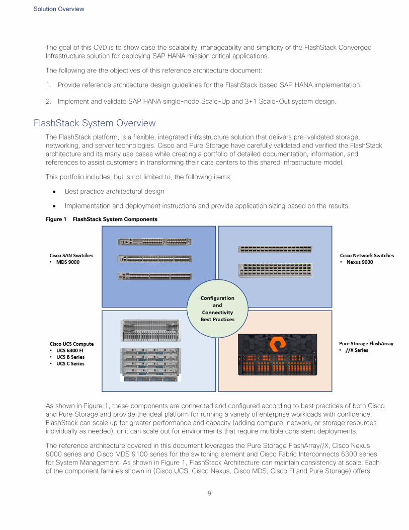
Figure 1 FlashStack System Components
As shown in Figure 1, these components are connected and configured according to best practices of both Cisco
and Pure Storage and provide the ideal platform for running a variety of enterprise workloads with confidence.
FlashStack can scale up for greater performance and capacity (adding compute, network, or storage resources
individually as needed), or it can scale out for environments that require multiple consistent deployments.
The reference architecture covered in this document leverages the Pure Storage FlashArray//X, Cisco Nexus
9000 series and Cisco MDS 9100 series for the switching element and Cisco Fabric Interconnects 6300 series
for System Management. As shown in Figure 1, FlashStack Architecture can maintain consistency at scale. Each
of the component families shown in (Cisco UCS, Cisco Nexus, Cisco MDS, Cisco FI and Pure Storage) offers
Solution Overview
10
platform and resource options to scale the infrastructure up or down, while supporting the same features and
functionality that are required under the configuration and connectivity best practices of FlashStack.
Design Principles
The FlashStack for SAP HANA solution addresses the following primary design principles:
Repeatable: Create a scalable building block that can be easily replicated at any customer site. Publish the
version of various firmware under test and weed out any issues in the lab before customers deploy this
solution.
Available: Create a design that is resilient and not prone to failure of a single component. For example, we
include best practices to enforce multiple paths to storage, multiple NICs for connectivity, and high
availability (HA) clustering.
Efficient: Take advantage of inline data reduction, higher bandwidth and low latency of the Pure Storage
FlashArray//m used in the FlashStack solution.
Simple: Avoid unnecessary and/or complex tweaks to make the results look better than a normal out-of-
box environment.
FlashStack Solution Benefits
Key Benefits of the FlashStack solution are:
Consistent Performance and Scalability
— Consistent sub-millisecond latency with 100 percent flash storage
— Consolidate hundreds of enterprise-class applications in a single rack
— Scalability through a design for hundreds of discrete servers and thousands of virtual machines, and
the capability to scale I/O bandwidth to match demand without disruption
— Repeatable growth through multiple FlashStack CI deployments
Operational Simplicity
— Fully tested, validated, and documented for rapid deployment
— Reduced management complexity
— No storage tuning or tiers necessary
— Auto-aligned 512b architecture eliminates storage alignment headaches
Improved TCO
— Dramatic savings in power, cooling and space with Cisco UCS and 100 percent Flash
Industry leading data reduction
Enterprise Grade Resiliency
— Highly available architecture and redundant components
— Non-disruptive operations

Solution Overview
11
— Upgrade and expand without downtime or performance loss
— Native data protection: snapshots and replication
Cisco and Pure Storage have also built a robust and experienced support team focused on FlashStack solutions,
from customer account and technical sales representatives to professional services and technical support
engineers. The support alliance between Pure Storage and Cisco gives customers and channel services partners
direct access to technical experts who collaborate with cross vendors and have access to shared lab resources
to resolve potential issues.
Infrastructure Requirements for the SAP HANA Database
12
Infrastructure Requirements for the SAP HANA Database
There are hardware and software requirements defined by SAP to run SAP HANA systems in Tailored Datacenter
Integration (TDI) option. This Cisco Validated Design uses guidelines provided by SAP.
Additional information is available at: http://saphana.com
CPU
SAP HANA2.0 (TDI) supports servers equipped with Intel Xeon processor E7-8880v3, E7-8890v3, E7-8880v4,
E7-8890v4 and all Skylake CPU’s > 8 cores. In addition, the Intel Xeon processor E5-26xx v4 is supported for
scale-up systems with the SAP HANA TDI option.
Memory
SAP HANA is supported in the following memory configurations:
Homogenous symmetric assembly of dual in-line memory modules (DIMMs) for example, DIMM size or
speed should not be mixed
Maximum use of all available memory channels
SAP HANA 2.0 Memory per socket up to 768 GB for SAP NetWeaver Business Warehouse (BW) and
DataMart
SAP HANA 2.0 Memory per socket up to 1536 GB for SAP Business Suite on SAP HANA (SoH) on 2- or
4-socket server
CPU and Memory Combinations
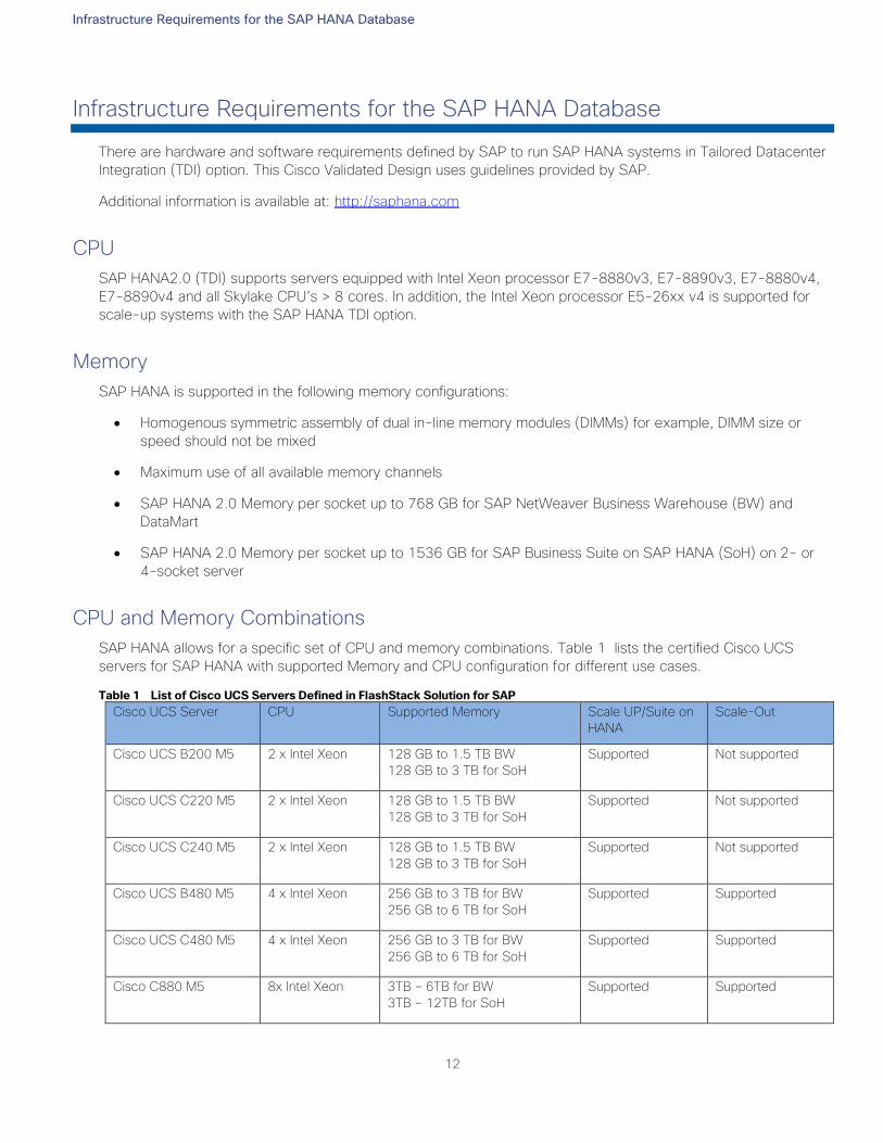
SAP HANA allows for a specific set of CPU and memory combinations. Table 1 lists the certified Cisco UCS
servers for SAP HANA with supported Memory and CPU configuration for different use cases.
Table 1 List of Cisco UCS Servers Defined in FlashStack Solution for SAP
Cisco UCS Server CPU Supported Memory
Scale UP/Suite on
HANA
Scale-Out
Cisco UCS B200 M5 2 x Intel Xeon 128 GB to 1.5 TB BW
128 GB to 3 TB for SoH
Supported Not supported
Cisco UCS C220 M5 2 x Intel Xeon 128 GB to 1.5 TB BW
128 GB to 3 TB for SoH
Supported Not supported
Cisco UCS C240 M5 2 x Intel Xeon 128 GB to 1.5 TB BW
128 GB to 3 TB for SoH
Supported Not supported
Cisco UCS B480 M5 4 x Intel Xeon 256 GB to 3 TB for BW
256 GB to 6 TB for SoH
Supported Supported
Cisco UCS C480 M5 4 x Intel Xeon 256 GB to 3 TB for BW
256 GB to 6 TB for SoH
Supported Supported
Cisco C880 M5 8x Intel Xeon 3TB – 6TB for BW
3TB – 12TB for SoH
Supported Supported
Infrastructure Requirements for the SAP HANA Database
13
Network
A SAP HANA data center deployment can range from a database running on a single host to a complex
distributed system. Distributed systems can get complex with multiple hosts located at a primary site having one
or more secondary sites; supporting a distributed multi-terabyte database with full fault and disaster recovery.
SAP HANA has different types of network communication channels to support the different SAP HANA scenarios
and setups:
Client zone: Channels used for external access to SAP HANA functions by end-user clients, administration
clients, and application servers, and for data provisioning through SQL or HTTP
Internal zone: Channels used for SAP HANA internal communication within the database or, in a distributed
scenario, for communication between hosts
Storage zone: Channels used for storage access (data persistence) and for backup and restore
procedures
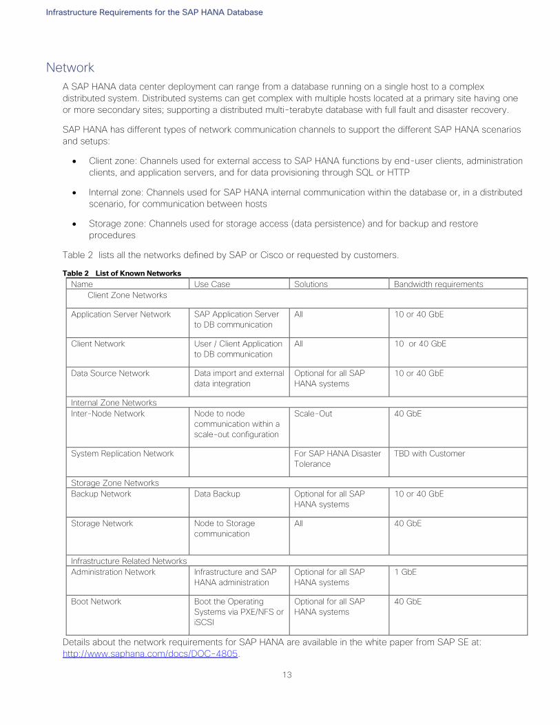
Table 2 lists all the networks defined by SAP or Cisco or requested by customers.
Table 2 List of Known Networks
Name Use Case Solutions Bandwidth requirements
Client Zone Networks
Application Server Network SAP Application Server
to DB communication
All 10 or 40 GbE
Client Network User / Client Application
to DB communication
All 10 or 40 GbE
Data Source Network Data import and external
data integration
Optional for all SAP
HANA systems
10 or 40 GbE
Internal Zone Networks
Inter-Node Network Node to node
communication within a
scale-out configuration
Scale-Out 40 GbE
System Replication Network For SAP HANA Disaster
Tolerance
TBD with Customer
Storage Zone Networks
Backup Network Data Backup Optional for all SAP
HANA systems
10 or 40 GbE
Storage Network Node to Storage
communication
All
40 GbE
Infrastructure Related Networks
Administration Network Infrastructure and SAP
HANA administration
Optional for all SAP
HANA systems
1 GbE
Boot Network Boot the Operating
Systems via PXE/NFS or
iSCSI
Optional for all SAP
HANA systems
40 GbE
Details about the network requirements for SAP HANA are available in the white paper from SAP SE at:
http://www.saphana.com/docs/DOC-4805.
Infrastructure Requirements for the SAP HANA Database
14
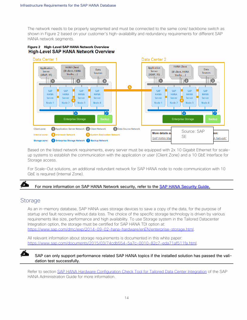
The network needs to be properly segmented and must be connected to the same core/ backbone switch as
shown in Figure 2 based on your customer’s high-availability and redundancy requirements for different SAP
HANA network segments.
Figure 2 High-Level SAP HANA Network Overview
Based on the listed network requirements, every server must be equipped with 2x 10 Gigabit Ethernet for scale-
up systems to establish the communication with the application or user (Client Zone) and a 10 GbE Interface for
Storage access.
For Scale-Out solutions, an additional redundant network for SAP HANA node to node communication with 10
GbE is required (Internal Zone).
For more information on SAP HANA Network security, refer to the SAP HANA Security Guide.
Storage
As an in-memory database, SAP HANA uses storage devices to save a copy of the data, for the purpose of
startup and fault recovery without data loss. The choice of the specific storage technology is driven by various
requirements like size, performance and high availability. To use Storage system in the Tailored Datacenter
Integration option, the storage must be certified for SAP HANA TDI option at:
https://www.sap.com/dmc/exp/2014-09-02-hana-hardware/enEN/enterprise-storage.html.
All relevant information about storage requirements is documented in this white paper:
https://www.sap.com/documents/2015/03/74cdb554-5a7c-0010-82c7-eda71af511fa.html.
SAP can only support performance related SAP HANA topics if the installed solution has passed the vali-
dation test successfully.
Refer to section SAP HANA Hardware Configuration Check Tool for Tailored Data Center Integration of the SAP
HANA Administration Guide for more information.
Source: SAP
SE
Infrastructure Requirements for the SAP HANA Database
15
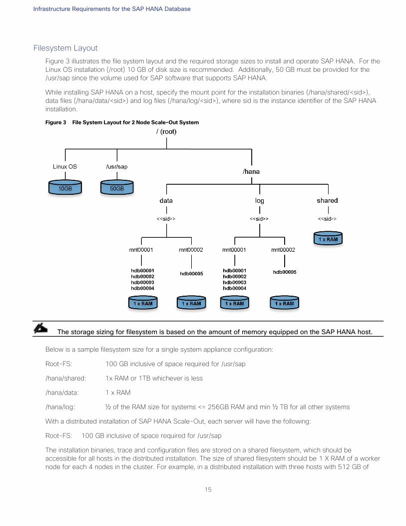
Filesystem Layout
Figure 3 illustrates the file system layout and the required storage sizes to install and operate SAP HANA. For the
Linux OS installation (/root) 10 GB of disk size is recommended. Additionally, 50 GB must be provided for the
/usr/sap since the volume used for SAP software that supports SAP HANA.
While installing SAP HANA on a host, specify the mount point for the installation binaries (/hana/shared/<sid>),
data files (/hana/data/<sid>) and log files (/hana/log/<sid>), where sid is the instance identifier of the SAP HANA
installation.
Figure 3 File System Layout for 2 Node Scale-Out System
The storage sizing for filesystem is based on the amount of memory equipped on the SAP HANA host.
Below is a sample filesystem size for a single system appliance configuration:
Root-FS: 100 GB inclusive of space required for /usr/sap
/hana/shared: 1x RAM or 1TB whichever is less
/hana/data: 1 x RAM
/hana/log: ½ of the RAM size for systems <= 256GB RAM and min ½ TB for all other systems
With a distributed installation of SAP HANA Scale-Out, each server will have the following:
Root-FS: 100 GB inclusive of space required for /usr/sap
The installation binaries, trace and configuration files are stored on a shared filesystem, which should be
accessible for all hosts in the distributed installation. The size of shared filesystem should be 1 X RAM of a worker
node for each 4 nodes in the cluster. For example, in a distributed installation with three hosts with 512 GB of
Infrastructure Requirements for the SAP HANA Database
16
memory each, shared file system should be 1 x 512 GB = 512 GB, for 5 hosts with 512 GB of memory each,
shared file system should be 2 x 512 GB = 1024GB.
For each SAP HANA host there should be a mount point for data and log volume. The size of the file system for
data volume with TDI option is one times the host memory:
/hana/data/<sid>/mntXXXXX: 1x RAM
For solutions based on Intel Skylake 81XX CPU the size of the Log volume must be as follows:
Half of the server RAM size for systems with ≤ 512 GB RAM
512 GB for systems with > 512 GB RAM
Operating System
The supported operating systems for SAP HANA are as follows:
SUSE Linux Enterprise Server for SAP Applications
RedHat Enterprise Linux for SAP HANA
High Availability
The infrastructure for a SAP HANA solution must not have single point of failure. To support high-availability, the
hardware and software requirements are:
Internal storage: A RAID-based configuration is preferred
External storage: Redundant data paths, dual controllers, and a RAID-based configuration are required
Ethernet switches: Two or more independent switches should be used
SAP HANA Scale-Out comes with in integrated high-availability function. If a SAP HANA system is configured with
a stand-by node, a failed part of SAP HANA will start on the stand-by node automatically. For automatic host
failover, storage connector API must be properly configured for the implementation and operation of the SAP
HANA.
For detailed information from SAP see: http://saphana.com or http://service.sap.com/notes.
Technology Overview
17
Technology Overview
This section provides a technical overview of products used in this solution.
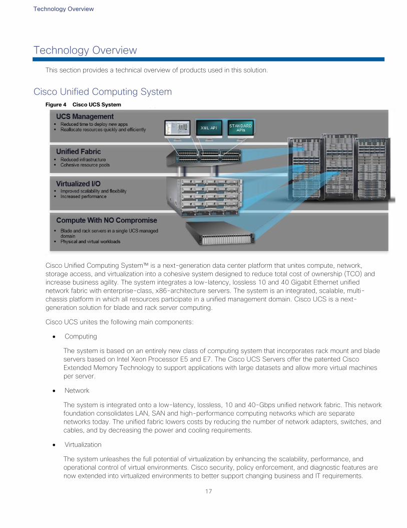
Cisco Unified Computing System Figure 4 Cisco UCS System
Cisco Unified Computing System™ is a next-generation data center platform that unites compute, network,
storage access, and virtualization into a cohesive system designed to reduce total cost of ownership (TCO) and
increase business agility. The system integrates a low-latency, lossless 10 and 40 Gigabit Ethernet unified
network fabric with enterprise-class, x86-architecture servers. The system is an integrated, scalable, multi-
chassis platform in which all resources participate in a unified management domain. Cisco UCS is a next-
generation solution for blade and rack server computing.
Cisco UCS unites the following main components:
Computing
The system is based on an entirely new class of computing system that incorporates rack mount and blade
servers based on Intel Xeon Processor E5 and E7. The Cisco UCS Servers offer the patented Cisco
Extended Memory Technology to support applications with large datasets and allow more virtual machines
per server.
Network
The system is integrated onto a low-latency, lossless, 10 and 40-Gbps unified network fabric. This network
foundation consolidates LAN, SAN and high-performance computing networks which are separate
networks today. The unified fabric lowers costs by reducing the number of network adapters, switches, and
cables, and by decreasing the power and cooling requirements.
Virtualization
The system unleashes the full potential of virtualization by enhancing the scalability, performance, and
operational control of virtual environments. Cisco security, policy enforcement, and diagnostic features are
now extended into virtualized environments to better support changing business and IT requirements.
Technology Overview
18
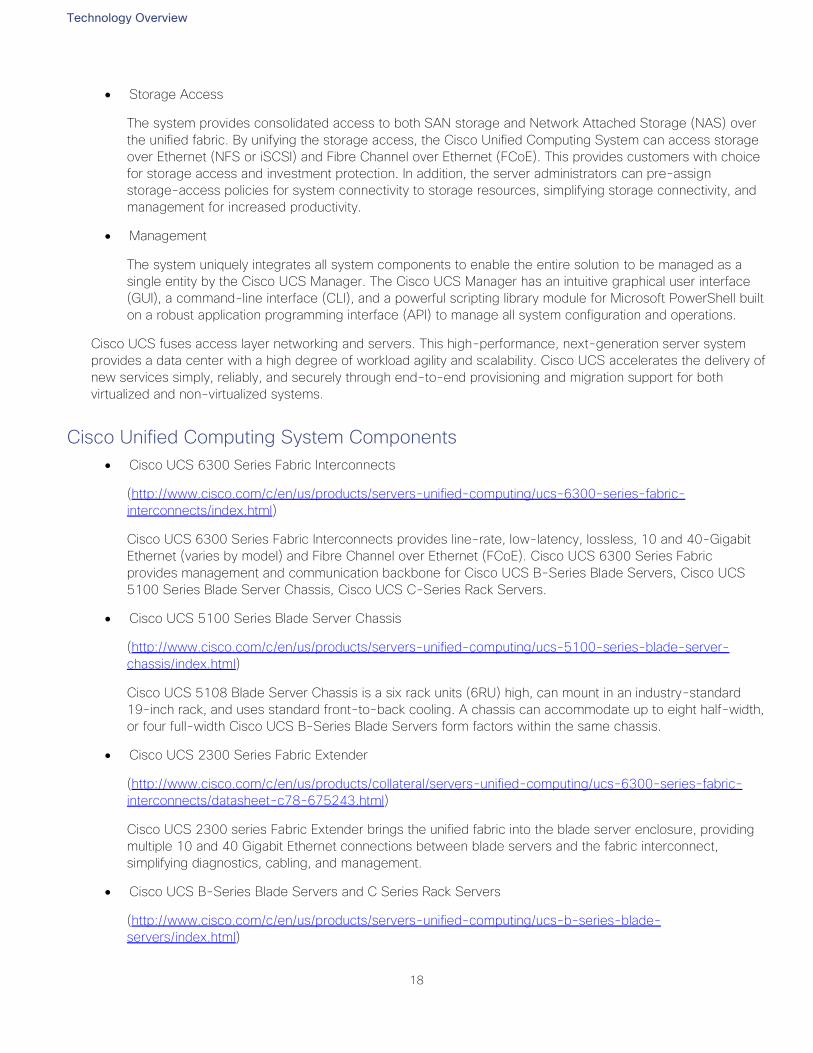
Storage Access
The system provides consolidated access to both SAN storage and Network Attached Storage (NAS) over
the unified fabric. By unifying the storage access, the Cisco Unified Computing System can access storage
over Ethernet (NFS or iSCSI) and Fibre Channel over Ethernet (FCoE). This provides customers with choice
for storage access and investment protection. In addition, the server administrators can pre-assign
storage-access policies for system connectivity to storage resources, simplifying storage connectivity, and
management for increased productivity.
Management
The system uniquely integrates all system components to enable the entire solution to be managed as a
single entity by the Cisco UCS Manager. The Cisco UCS Manager has an intuitive graphical user interface
(GUI), a command-line interface (CLI), and a powerful scripting library module for Microsoft PowerShell built
on a robust application programming interface (API) to manage all system configuration and operations.
Cisco UCS fuses access layer networking and servers. This high-performance, next-generation server system
provides a data center with a high degree of workload agility and scalability. Cisco UCS accelerates the delivery of
new services simply, reliably, and securely through end-to-end provisioning and migration support for both
virtualized and non-virtualized systems.
Cisco Unified Computing System Components
Cisco UCS 6300 Series Fabric Interconnects
(http://www.cisco.com/c/en/us/products/servers-unified-computing/ucs-6300-series-fabric-
interconnects/index.html)
Cisco UCS 6300 Series Fabric Interconnects provides line-rate, low-latency, lossless, 10 and 40-Gigabit
Ethernet (varies by model) and Fibre Channel over Ethernet (FCoE). Cisco UCS 6300 Series Fabric
provides management and communication backbone for Cisco UCS B-Series Blade Servers, Cisco UCS
5100 Series Blade Server Chassis, Cisco UCS C-Series Rack Servers.
Cisco UCS 5100 Series Blade Server Chassis
(http://www.cisco.com/c/en/us/products/servers-unified-computing/ucs-5100-series-blade-server-
chassis/index.html)
Cisco UCS 5108 Blade Server Chassis is a six rack units (6RU) high, can mount in an industry-standard
19-inch rack, and uses standard front-to-back cooling. A chassis can accommodate up to eight half-width,
or four full-width Cisco UCS B-Series Blade Servers form factors within the same chassis.
Cisco UCS 2300 Series Fabric Extender
(http://www.cisco.com/c/en/us/products/collateral/servers-unified-computing/ucs-6300-series-fabric-
interconnects/datasheet-c78-675243.html)
Cisco UCS 2300 series Fabric Extender brings the unified fabric into the blade server enclosure, providing
multiple 10 and 40 Gigabit Ethernet connections between blade servers and the fabric interconnect,
simplifying diagnostics, cabling, and management.
Cisco UCS B-Series Blade Servers and C Series Rack Servers
(http://www.cisco.com/c/en/us/products/servers-unified-computing/ucs-b-series-blade-
servers/index.html)
Technology Overview
19
(http://www.cisco.com/c/en/us/products/servers-unified-computing/ucs-c-series-rack-
servers/index.html)
Based on Intel® Xeon® processor E7 and E5 product families and the latest Skylake processors, Cisco UCS
Servers work with virtualized and non-virtualized applications to increase:
— Performance
— Energy efficiency
— Flexibility
— Administrator productivity
Cisco UCS Adapters
(http://www.cisco.com/c/en/us/products/interfaces-modules/unified-computing-system-
adapters/index.html)
The Cisco Unified Computing System supports Converged Network Adapters (CNAs) obviate the need for
multiple network interface cards (NICs) and host bus adapters (HBAs) by converging LAN and SAN traffic in
a single interface.
Cisco UCS Manager
(http://www.cisco.com/c/en/us/products/servers-unified-computing/ucs-manager/index.html)
Streamline many of your most time-consuming daily activities, including configuration, provisioning,
monitoring, and problem resolution with Cisco UCS Manager. It reduces TCO and simplifies daily operations
to generate significant savings.
Cisco Nexus 9000 Series Switches
(http://www.cisco.com/c/en/us/products/switches/nexus-9000-series-switches/index.html)
The 9000 Series offers modular 9500 switches and fixed 9300 and 9200 switches with
1/10/25/50/40/100 Gigabit Ethernet switch configurations. 9200 switches are optimized for high
performance and density in NX-OS mode operations.
Cisco MDS 9100 Series Multilayer Fabric Switches
(http://www.cisco.com/c/en/us/products/storage-networking/mds-9100-series-multilayer-fabric-
switches/index.html)
The Cisco MDS 9100 Series Multilayer Fabric Switches consists of Cisco MDS 9148S, a 48-port, 16 Gbps
Fibre Channel switch, and the Cisco MDS 9148, a 48-port 8 Gbps Fibre Channel switch.
Cisco UCS Manager
Cisco UCS Manager (UCSM) provides unified, centralized, embedded management of all Cisco UCS software
and hardware components across multiple chassis and thousands of virtual machines. Administrators use the
software to manage the entire Cisco UCS as a single logical entity through an intuitive GUI, a command-line
interface (CLI), or an XML API.
Cisco UCS Manager manages Cisco UCS systems through an intuitive HTML 5 or Java user interface and a
command-line interface (CLI) enabling centralized management of distributed systems scaling to thousands of
http://www.cisco.com/c/en/us/products/servers-unified-computing/ucs-c-series-rack-servers/index.html
Technology Overview
20
servers. Cisco UCS Manager is embedded on a pair of Cisco UCS 6300 Series Fabric Interconnects using a
clustered, active-standby configuration for high availability. The manager gives administrators a single interface for
performing server provisioning, device discovery, inventory, configuration, diagnostics, monitoring, fault detection,
auditing, and statistics collection.
Cisco UCS management software provides a model-based foundation for streamlining the day-to-day processes
of updating, monitoring, and managing computing resources, local storage, storage connections, and network
connections. By enabling better automation of processes, Cisco UCS Manager allows IT organizations to achieve
greater agility and scale in their infrastructure operations while reducing complexity and risk.
Cisco UCS Manager provides an easier, faster, more flexible, and unified solution for managing firmware across
the entire hardware stack than traditional approaches to server firmware provisioning. Using service profiles,
administrators can associate any compatible firmware with any component of the hardware stack. After the
firmware versions are downloaded from Cisco, they can be provisioned within minutes on components in the
server, fabric interconnect, and fabric extender based on the required network, server, and storage policies for
each application and operating system. The firmware’s auto-installation capability simplifies the upgrade process
by automatically sequencing and applying upgrades to individual system elements.
Some of the key elements managed by Cisco UCS Manager include:
Cisco UCS Integrated Management Controller (IMC) firmware
RAID controller firmware and settings
BIOS firmware and settings, including server universal user ID (UUID) and boot order
Converged network adapter (CNA) firmware and settings, including MAC addresses and worldwide names
(WWNs) and SAN boot settings
Virtual port groups used by virtual machines, using Cisco Data Center VM-FEX technology
Interconnect configuration, including uplink and downlink definitions, MAC address and WWN pinning,
VLANs, VSANs, quality of service (QoS), bandwidth allocations, Cisco Data Center VM-FEX settings, and
Ether Channels to upstream LAN switches
Cisco UCS Manager provides end-to-end management of all the devices in the Cisco UCS domain it manages.
Devices that are uplinked from the fabric interconnect must be managed by their respective management
applications.
Cisco UCS Manager is provided at no additional charge with every Cisco UCS platform.
For more information on Cisco UCS Manager, see:
http://www.cisco.com/c/en/us/products/servers-unified-computing/ucs-manager/index.html
Cisco UCS Service Profile
Service profiles are essential to the automation functions in Cisco UCS Manager. They provision and manage
Cisco UCS systems and their I/O properties within a Cisco UCS domain. Infrastructure policies are created by
server, network, and storage administrators and are stored in the Cisco UCS Fabric Interconnects. The
infrastructure policies needed to deploy applications are encapsulated in the service profiles templates, which are
collections of policies needed for the specific applications. The service profile templates are then used to create
one or more service profiles, which provide the complete definition of the server. The policies coordinate and
automate element management at every layer of the hardware stack, including RAID levels, BIOS settings,
Technology Overview
21
firmware revisions and settings, server identities, adapter settings, VLAN and VSAN network settings, network
quality of service (QoS), and data center connectivity.
A server’s identity is made up of many properties such as UUID, boot order, IPMI settings, BIOS firmware, BIOS
settings, RAID settings, disk scrub settings, number of NICs, NIC speed, NIC firmware, MAC and IP addresses,
number of HBAs, HBA WWNs, HBA firmware, FC fabric assignments, QoS settings, VLAN assignments, remote
keyboard/video/monitor etc. I think you get the idea. It’s a LONG list of “points of configuration” that need to be
configured to give this server its identity and make it unique from every other server within your data center.
Some of these parameters are kept in the hardware of the server itself (like BIOS firmware version, BIOS settings,
boot order, FC boot settings, etc.) while some settings are kept on your network and storage switches (like VLAN
assignments, FC fabric assignments, QoS settings, ACLs, etc.). This results in following server deployment
challenges:
Every deployment requires coordination among server, storage, and network teams
Need to ensure correct firmware and settings for hardware components
Need appropriate LAN and SAN connectivity
The service profile consists of a software definition of a server and the associated LAN and SAN connectivity that
the server requires. When a service profile is associated with a server, Cisco UCS Manager automatically
configures the server, adapters, fabric extenders, and fabric interconnects to match the configuration specified in
the service profile. Service profiles improve IT productivity and business agility because they establish the best
practices of your subject-matter experts in software. With service profiles, infrastructure can be provisioned in
minutes instead of days, shifting the focus of IT staff from maintenance to strategic initiatives. Service profiles
enable pre-provisioning of servers, enabling organizations to configure new servers and associated LAN and SAN
access settings even before the servers are physically deployed.
Cisco UCS Service Profiles contain values for a server's property settings, including virtual network interface
cards (vNICs), MAC addresses, boot policies, firmware policies, fabric connectivity, external management, and HA
information. By abstracting these settings from the physical server into a Cisco Service Profile, the Service Profile
can then be deployed to any physical compute hardware within the Cisco UCS domain. Furthermore, Service
Profiles can, at any time, be migrated from one physical server to another. This logical abstraction of the server
personality separates the dependency of the hardware type or model and is a result of Cisco’s unified fabric
model (rather than overlaying software tools on top).
Technology Overview
22
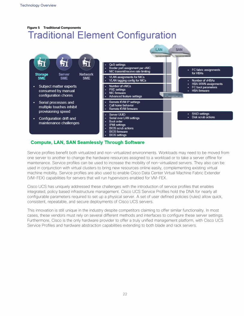
Figure 5 Traditional Components
Service profiles benefit both virtualized and non-virtualized environments. Workloads may need to be moved from
one server to another to change the hardware resources assigned to a workload or to take a server offline for
maintenance. Service profiles can be used to increase the mobility of non-virtualized servers. They also can be
used in conjunction with virtual clusters to bring new resources online easily, complementing existing virtual
machine mobility. Service profiles are also used to enable Cisco Data Center Virtual Machine Fabric Extender
(VM-FEX) capabilities for servers that will run hypervisors enabled for VM-FEX.
Cisco UCS has uniquely addressed these challenges with the introduction of service profiles that enables
integrated, policy based infrastructure management. Cisco UCS Service Profiles hold the DNA for nearly all
configurable parameters required to set up a physical server. A set of user defined policies (rules) allow quick,
consistent, repeatable, and secure deployments of Cisco UCS servers.
This innovation is still unique in the industry despite competitors claiming to offer similar functionality. In most
cases, these vendors must rely on several different methods and interfaces to configure these server settings.
Furthermore, Cisco is the only hardware provider to offer a truly unified management platform, with Cisco UCS
Service Profiles and hardware abstraction capabilities extending to both blade and rack servers.
Technology Overview
23
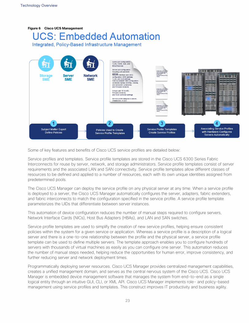
Figure 6 Cisco UCS Management
Some of key features and benefits of Cisco UCS service profiles are detailed below:
Service profiles and templates. Service profile templates are stored in the Cisco UCS 6300 Series Fabric
Interconnects for reuse by server, network, and storage administrators. Service profile templates consist of server
requirements and the associated LAN and SAN connectivity. Service profile templates allow different classes of
resources to be defined and applied to a number of resources, each with its own unique identities assigned from
predetermined pools.
The Cisco UCS Manager can deploy the service profile on any physical server at any time. When a service profile
is deployed to a server, the Cisco UCS Manager automatically configures the server, adapters, fabric extenders,
and fabric interconnects to match the configuration specified in the service profile. A service profile template
parameterizes the UIDs that differentiate between server instances.
This automation of device configuration reduces the number of manual steps required to configure servers,
Network Interface Cards (NICs), Host Bus Adapters (HBAs), and LAN and SAN switches.
Service profile templates are used to simplify the creation of new service profiles, helping ensure consistent
policies within the system for a given service or application. Whereas a service profile is a description of a logical
server and there is a one-to-one relationship between the profile and the physical server, a service profile
template can be used to define multiple servers. The template approach enables you to configure hundreds of
servers with thousands of virtual machines as easily as you can configure one server. This automation reduces
the number of manual steps needed, helping reduce the opportunities for human error, improve consistency, and
further reducing server and network deployment times.
Programmatically deploying server resources. Cisco UCS Manager provides centralized management capabilities,
creates a unified management domain, and serves as the central nervous system of the Cisco UCS. Cisco UCS
Manager is embedded device management software that manages the system from end-to-end as a single
logical entity through an intuitive GUI, CLI, or XML API. Cisco UCS Manager implements role- and policy-based
management using service profiles and templates. This construct improves IT productivity and business agility.
Technology Overview
24
Now infrastructure can be provisioned in minutes instead of days, shifting IT’s focus from maintenance to strategic
initiatives.
Dynamic provisioning. Cisco UCS resources are abstract in the sense that their identity, I/O configuration, MAC
addresses and WWNs, firmware versions, BIOS boot order, and network attributes (including QoS settings, ACLs,
pin groups, and threshold policies) all are programmable using a just-in-time deployment model. A service profile
can be applied to any blade server to provision it with the characteristics required to support a specific software
stack. A service profile allows server and network definitions to move within the management domain, enabling
flexibility in the use of system resources. Service profile templates allow different classes of resources to be
defined and applied to a number of resources, each with its own unique identities assigned from predetermined
pools.
Cisco UCS 6300 Unified Fabric Interconnects
The Cisco UCS 6300 Series Fabric Interconnects are a core part of Cisco UCS, providing both network
connectivity and management capabilities for the system. The Cisco UCS 6300 Series offers line-rate, low-
latency, lossless 10 and 40 Gigabit Ethernet, Fibre Channel over Ethernet (FCoE), and Fibre Channel functions.
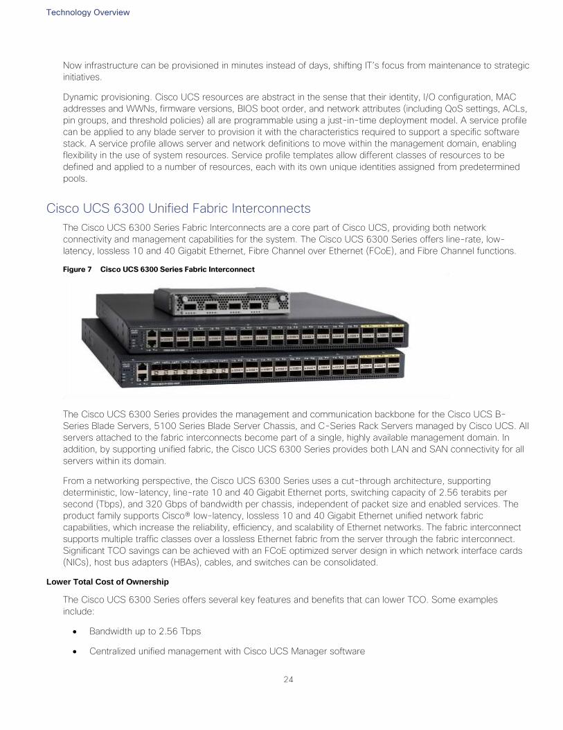
Figure 7 Cisco UCS 6300 Series Fabric Interconnect
The Cisco UCS 6300 Series provides the management and communication backbone for the Cisco UCS B-
Series Blade Servers, 5100 Series Blade Server Chassis, and C-Series Rack Servers managed by Cisco UCS. All
servers attached to the fabric interconnects become part of a single, highly available management domain. In
addition, by supporting unified fabric, the Cisco UCS 6300 Series provides both LAN and SAN connectivity for all
servers within its domain.
From a networking perspective, the Cisco UCS 6300 Series uses a cut-through architecture, supporting
deterministic, low-latency, line-rate 10 and 40 Gigabit Ethernet ports, switching capacity of 2.56 terabits per
second (Tbps), and 320 Gbps of bandwidth per chassis, independent of packet size and enabled services. The
product family supports Cisco® low-latency, lossless 10 and 40 Gigabit Ethernet unified network fabric
capabilities, which increase the reliability, efficiency, and scalability of Ethernet networks. The fabric interconnect
supports multiple traffic classes over a lossless Ethernet fabric from the server through the fabric interconnect.
Significant TCO savings can be achieved with an FCoE optimized server design in which network interface cards
(NICs), host bus adapters (HBAs), cables, and switches can be consolidated.
Lower Total Cost of Ownership
The Cisco UCS 6300 Series offers several key features and benefits that can lower TCO. Some examples
include:
Bandwidth up to 2.56 Tbps
Centralized unified management with Cisco UCS Manager software
Technology Overview
25
Highly Scalable Architecture
Cisco Fabric Extender technology scales up to 20 chassis in just one unified system without additional complexity.
The result is that customers can eliminate dedicated chassis management and blade switches, as well as reduce
cabling.
Cisco UCS 6300 Series Fabric Interconnect Models
Cisco UCS 6332 and 6332-16UP Fabric Interconnects
These top-of-rack (ToR) switches manage domains of up to 160 servers.
Table 3 Fabric Interconnect Specifications
Feature FI 6332 FI 6332-16UP
Height 1 RU 1 RU
Physical Ports 32 40
Max 10G Ports 98 88
Max 40G Ports 32 24
Max FC Ports 0 16 x 4/8/16 G
Unified Ports 0 16
Default Port Licenses 8 4/24, 8/16 UP
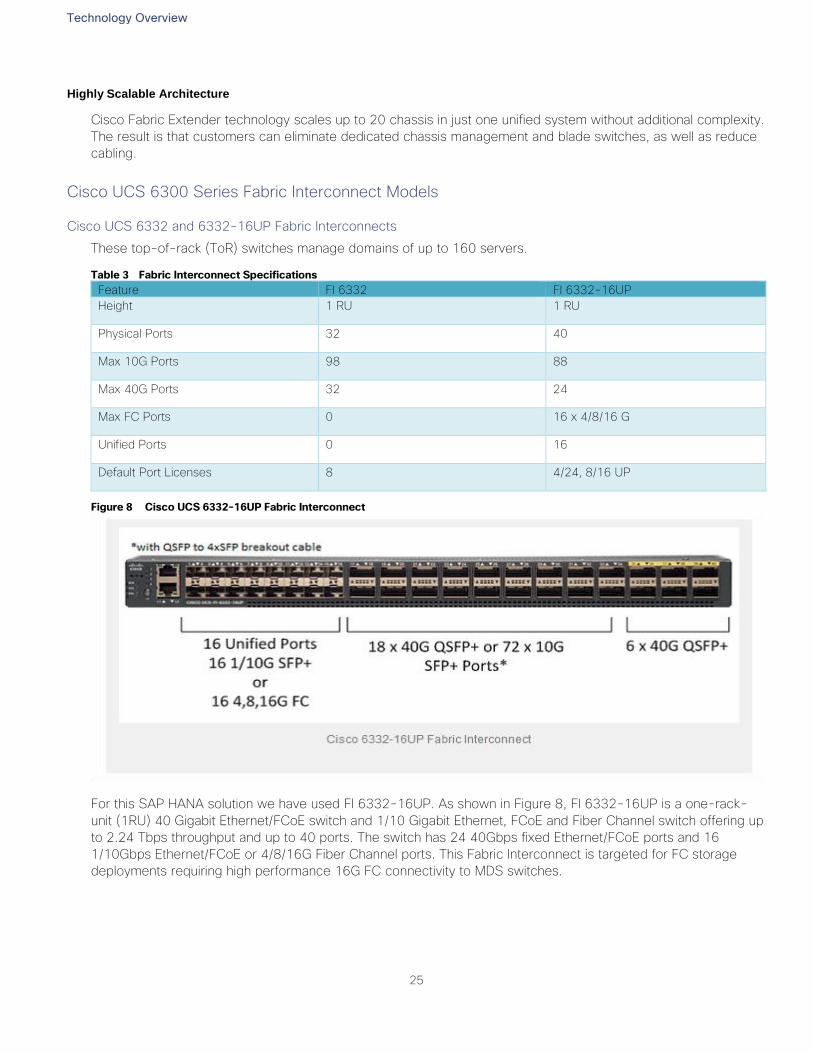
Figure 8 Cisco UCS 6332-16UP Fabric Interconnect
For this SAP HANA solution we have used FI 6332-16UP. As shown in Figure 8, FI 6332-16UP is a one-rack-
unit (1RU) 40 Gigabit Ethernet/FCoE switch and 1/10 Gigabit Ethernet, FCoE and Fiber Channel switch offering up
to 2.24 Tbps throughput and up to 40 ports. The switch has 24 40Gbps fixed Ethernet/FCoE ports and 16
1/10Gbps Ethernet/FCoE or 4/8/16G Fiber Channel ports. This Fabric Interconnect is targeted for FC storage
deployments requiring high performance 16G FC connectivity to MDS switches.

Technology Overview
26
Cisco UCS 2304XP Fabric Extender
The Cisco UCS 2304 Fabric Extender has four 40 Gigabit Ethernet, FCoE-capable, Quad Small Form-Factor
Pluggable (QSFP+) ports that connect the blade chassis to the fabric interconnect. Each Cisco UCS 2304 has
four 40 Gigabit Ethernet ports connected through the midplane to each half-width slot in the chassis. Typically
configured in pairs for redundancy, two fabric extenders provide up to 320 Gbps of I/O to the chassis.
Figure 9 Cisco UCS 2304 XP
Cisco UCS Blade Chassis
The Cisco UCS 5100 Series Blade Server Chassis is a crucial building block of Cisco Unified Computing System,
delivering a scalable and flexible blade server.
The Cisco UCS 5108 Blade Server Chassis is six rack units (6RU) high and can mount in an industry standard
19-inch rack. A single chassis can house up to eight half-width Cisco UCS B-Series Blade Servers and can
accommodate both half-width and full-width blade form factors. Four hot-swappable power supplies are
accessible from the front of the chassis, and single-phase AC, –48V DC, and 200 to 380V DC power supplies
and chassis are available. These power supplies are up to 94 percent efficient and meet the requirements for the
80 Plus Platinum rating. The power subsystem can be configured to support nonredundant, N+1 redundant, and
grid-redundant configurations. The rear of the chassis contains eight hot-swappable fans, four power connectors
(one per power supply), and two I/O bays that can support either Cisco UCS 2000 Series Fabric Extenders or the
Cisco UCS 6324 Fabric Interconnect. A passive midplane provides up to 80 Gbps of I/O bandwidth per server
slot and up to 160 Gbps of I/O bandwidth for two slots.
The Cisco UCS Blade Server Chassis is shown in Figure 10.
Figure 10 Cisco Blade Server Chassis (front and back view)
Cisco UCS B480 M5 Blade Server
The enterprise-class Cisco UCS B480 M5 Blade Server delivers market-leading performance, versatility, and
density without compromise for memory-intensive mission-critical enterprise applications and virtualized
workloads, among others. With the Cisco UCS B480 M5, you can quickly deploy stateless physical and virtual
workloads with the programmability that Cisco UCS Manager and Cisco® SingleConnect technology enable.
The Cisco UCS B480 M5 is a full-width blade server supported by the Cisco UCS 5108 Blade Server Chassis.
The Cisco UCS 5108 chassis and the Cisco UCS B-Series Blade Servers provide inherent architectural
advantages:
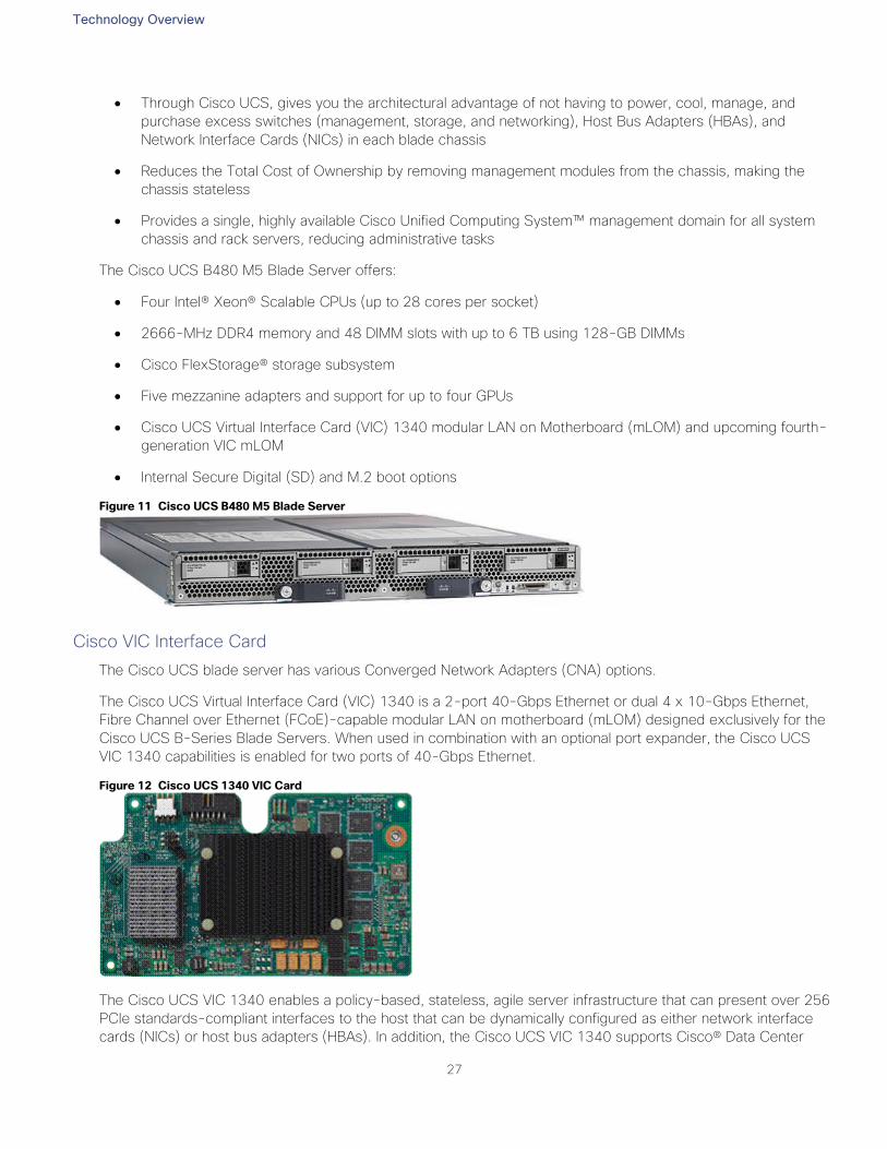
Technology Overview
27
Through Cisco UCS, gives you the architectural advantage of not having to power, cool, manage, and
purchase excess switches (management, storage, and networking), Host Bus Adapters (HBAs), and
Network Interface Cards (NICs) in each blade chassis
Reduces the Total Cost of Ownership by removing management modules from the chassis, making the
chassis stateless
Provides a single, highly available Cisco Unified Computing System™ management domain for all system
chassis and rack servers, reducing administrative tasks
The Cisco UCS B480 M5 Blade Server offers:
Four Intel® Xeon® Scalable CPUs (up to 28 cores per socket)
2666-MHz DDR4 memory and 48 DIMM slots with up to 6 TB using 128-GB DIMMs
Cisco FlexStorage® storage subsystem
Five mezzanine adapters and support for up to four GPUs
Cisco UCS Virtual Interface Card (VIC) 1340 modular LAN on Motherboard (mLOM) and upcoming fourth-
generation VIC mLOM
Internal Secure Digital (SD) and M.2 boot options
Figure 11 Cisco UCS B480 M5 Blade Server
Cisco VIC Interface Card
The Cisco UCS blade server has various Converged Network Adapters (CNA) options.
The Cisco UCS Virtual Interface Card (VIC) 1340 is a 2-port 40-Gbps Ethernet or dual 4 x 10-Gbps Ethernet,
Fibre Channel over Ethernet (FCoE)-capable modular LAN on motherboard (mLOM) designed exclusively for the
Cisco UCS B-Series Blade Servers. When used in combination with an optional port expander, the Cisco UCS
VIC 1340 capabilities is enabled for two ports of 40-Gbps Ethernet.
Figure 12 Cisco UCS 1340 VIC Card
The Cisco UCS VIC 1340 enables a policy-based, stateless, agile server infrastructure that can present over 256
PCIe standards-compliant interfaces to the host that can be dynamically configured as either network interface
cards (NICs) or host bus adapters (HBAs). In addition, the Cisco UCS VIC 1340 supports Cisco® Data Center
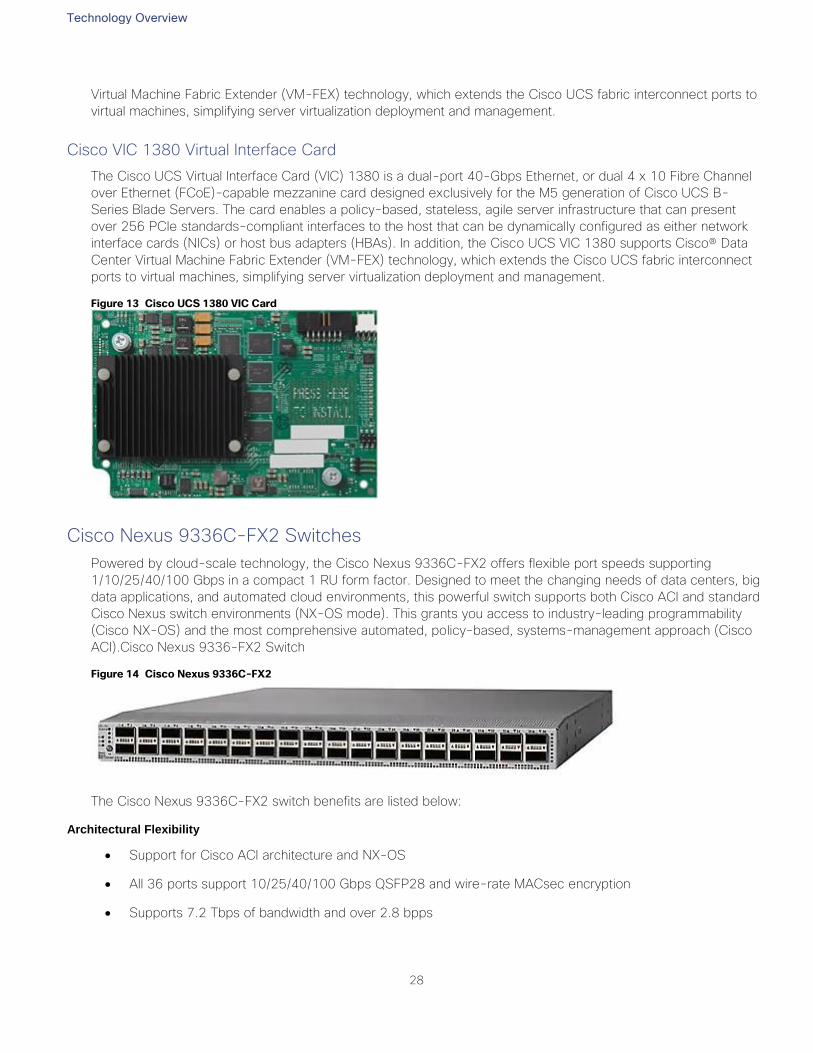
Technology Overview
28
Virtual Machine Fabric Extender (VM-FEX) technology, which extends the Cisco UCS fabric interconnect ports to
virtual machines, simplifying server virtualization deployment and management.
Cisco VIC 1380 Virtual Interface Card
The Cisco UCS Virtual Interface Card (VIC) 1380 is a dual-port 40-Gbps Ethernet, or dual 4 x 10 Fibre Channel
over Ethernet (FCoE)-capable mezzanine card designed exclusively for the M5 generation of Cisco UCS B-
Series Blade Servers. The card enables a policy-based, stateless, agile server infrastructure that can present
over 256 PCIe standards-compliant interfaces to the host that can be dynamically configured as either network
interface cards (NICs) or host bus adapters (HBAs). In addition, the Cisco UCS VIC 1380 supports Cisco® Data
Center Virtual Machine Fabric Extender (VM-FEX) technology, which extends the Cisco UCS fabric interconnect
ports to virtual machines, simplifying server virtualization deployment and management.
Figure 13 Cisco UCS 1380 VIC Card
Cisco Nexus 9336C-FX2 Switches
Powered by cloud-scale technology, the Cisco Nexus 9336C-FX2 offers flexible port speeds supporting
1/10/25/40/100 Gbps in a compact 1 RU form factor. Designed to meet the changing needs of data centers, big
data applications, and automated cloud environments, this powerful switch supports both Cisco ACI and standard
Cisco Nexus switch environments (NX-OS mode). This grants you access to industry-leading programmability
(Cisco NX-OS) and the most comprehensive automated, policy-based, systems-management approach (Cisco
ACI).Cisco Nexus 9336-FX2 Switch
Figure 14 Cisco Nexus 9336C-FX2
The Cisco Nexus 9336C-FX2 switch benefits are listed below:
Architectural Flexibility
Support for Cisco ACI architecture and NX-OS
All 36 ports support 10/25/40/100 Gbps QSFP28 and wire-rate MACsec encryption
Supports 7.2 Tbps of bandwidth and over 2.8 bpps
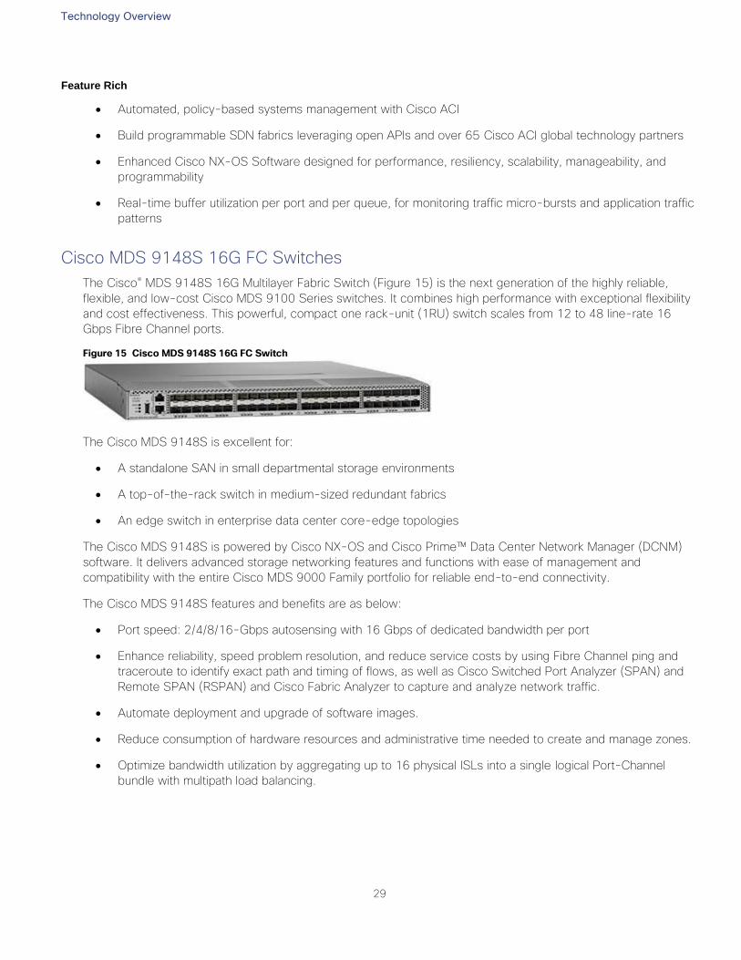
Technology Overview
29
Feature Rich
Automated, policy-based systems management with Cisco ACI
Build programmable SDN fabrics leveraging open APIs and over 65 Cisco ACI global technology partners
Enhanced Cisco NX-OS Software designed for performance, resiliency, scalability, manageability, and
programmability
Real-time buffer utilization per port and per queue, for monitoring traffic micro-bursts and application traffic
patterns
Cisco MDS 9148S 16G FC Switches
The Cisco® MDS 9148S 16G Multilayer Fabric Switch (Figure 15) is the next generation of the highly reliable,
flexible, and low-cost Cisco MDS 9100 Series switches. It combines high performance with exceptional flexibility
and cost effectiveness. This powerful, compact one rack-unit (1RU) switch scales from 12 to 48 line-rate 16
Gbps Fibre Channel ports.
Figure 15 Cisco MDS 9148S 16G FC Switch
The Cisco MDS 9148S is excellent for:
A standalone SAN in small departmental storage environments
A top-of-the-rack switch in medium-sized redundant fabrics
An edge switch in enterprise data center core-edge topologies
The Cisco MDS 9148S is powered by Cisco NX-OS and Cisco Prime™ Data Center Network Manager (DCNM)
software. It delivers advanced storage networking features and functions with ease of management and
compatibility with the entire Cisco MDS 9000 Family portfolio for reliable end-to-end connectivity.
The Cisco MDS 9148S features and benefits are as below:
Port speed: 2/4/8/16-Gbps autosensing with 16 Gbps of dedicated bandwidth per port
Enhance reliability, speed problem resolution, and reduce service costs by using Fibre Channel ping and
traceroute to identify exact path and timing of flows, as well as Cisco Switched Port Analyzer (SPAN) and
Remote SPAN (RSPAN) and Cisco Fabric Analyzer to capture and analyze network traffic.
Automate deployment and upgrade of software images.
Reduce consumption of hardware resources and administrative time needed to create and manage zones.
Optimize bandwidth utilization by aggregating up to 16 physical ISLs into a single logical Port-Channel
bundle with multipath load balancing.
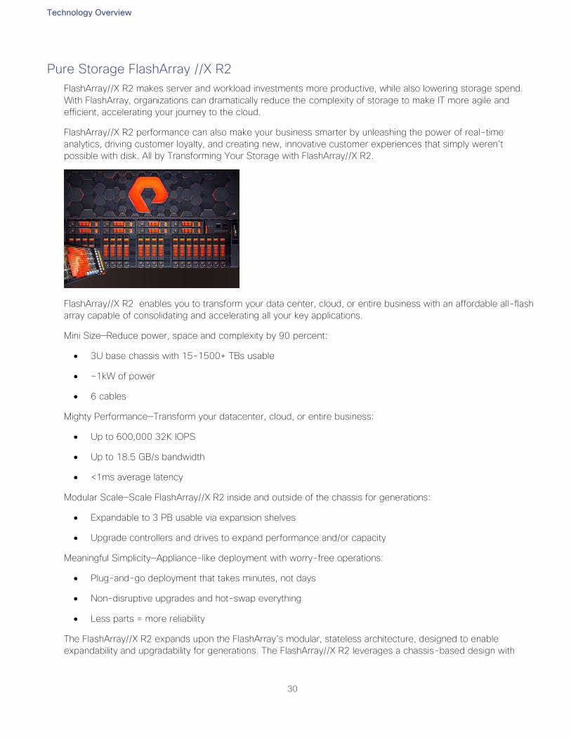
Technology Overview
30
Pure Storage FlashArray //X R2
FlashArray//X R2 makes server and workload investments more productive, while also lowering storage spend.
With FlashArray, organizations can dramatically reduce the complexity of storage to make IT more agile and
efficient, accelerating your journey to the cloud.
FlashArray//X R2 performance can also make your business smarter by unleashing the power of real-time
analytics, driving customer loyalty, and creating new, innovative customer experiences that simply weren’t
possible with disk. All by Transforming Your Storage with FlashArray//X R2.
FlashArray//X R2 enables you to transform your data center, cloud, or entire business with an affordable all-flash
array capable of consolidating and accelerating all your key applications.
Mini Size—Reduce power, space and complexity by 90 percent:
3U base chassis with 15-1500+ TBs usable
~1kW of power
6 cables
Mighty Performance—Transform your datacenter, cloud, or entire business:
Up to 600,000 32K IOPS
Up to 18.5 GB/s bandwidth
<1ms average latency
Modular Scale—Scale FlashArray//X R2 inside and outside of the chassis for generations:
Expandable to 3 PB usable via expansion shelves
Upgrade controllers and drives to expand performance and/or capacity
Meaningful Simplicity—Appliance-like deployment with worry-free operations:
Plug-and-go deployment that takes minutes, not days
Non-disruptive upgrades and hot-swap everything
Less parts = more reliability
The FlashArray//X R2 expands upon the FlashArray’s modular, stateless architecture, designed to enable
expandability and upgradability for generations. The FlashArray//X R2 leverages a chassis-based design with

Technology Overview
31
customizable modules, enabling both capacity and performance to be independently improved over time with
advances in compute and flash, to meet your business’ needs today and tomorrow.
The Pure Storage FlashArray//X is ideal for:
Accelerating Databases and Applications Speed transactions by 10x with consistent low latency, enable online
data analytics across wide datasets, and mix production, analytics, dev/test, and backup workloads without fear.
Virtualizing and Consolidating Workloads Easily accommodate the most IO-hungry Tier 1 workloads, increase
consolidation rates (thereby reducing servers), simplify VI administration, and accelerate common administrative
tasks.
Delivering the Ultimate Virtual Desktop Experience Support demanding users with better performance than
physical desktops, scale without disruption from pilot to >1000’s of users, and experience all-flash performance
Protecting and Recovering Vital Data Assets Provide an always-on protection for business-critical data, maintain
performance even under failure conditions, and recover instantly with FlashRecover.
Pure Storage FlashArray//X sets the benchmark for all-flash enterprise storage arrays. It delivers:
Consistent Performance FlashArray delivers consistent <1ms average latency. Performance is optimized for the
real-world applications workloads that are dominated by I/O sizes of 32K or larger vs. 4K/8K hero performance
benchmarks. Full performance is maintained even under failures/updates.
Lower Cost than Disk Inline de-duplication and compression deliver 5 – 10x space savings across a broad set of
I/O workloads including Databases, Virtual Machines and Virtual Desktop Infrastructure.
Mission-Critical Resiliency FlashArray delivers >99.9999% proven availability, as measured across the Pure
Storage installed base and does so with non-disruptive everything without performance impact.
Disaster Recovery Built-In FlashArray offers native, fully-integrated, data reduction-optimized backup and disaster
recovery at no additional cost. Setup disaster recovery with policy-based automation within minutes. And, recover
instantly from local, space-efficient snapshots or remote replicas.
Simplicity Built-In FlashArray offers game-changing management simplicity that makes storage installation,
configuration, provisioning and migration a snap. No more managing performance, RAID, tiers or caching. Achieve
optimal application performance without any tuning at any layer. Manage the FlashArray the way you like it: Web-
based GUI, CLI, VMware® vCenter, Rest API, or OpenStack.
Figure 16 FlashArray//X R2 Specifications
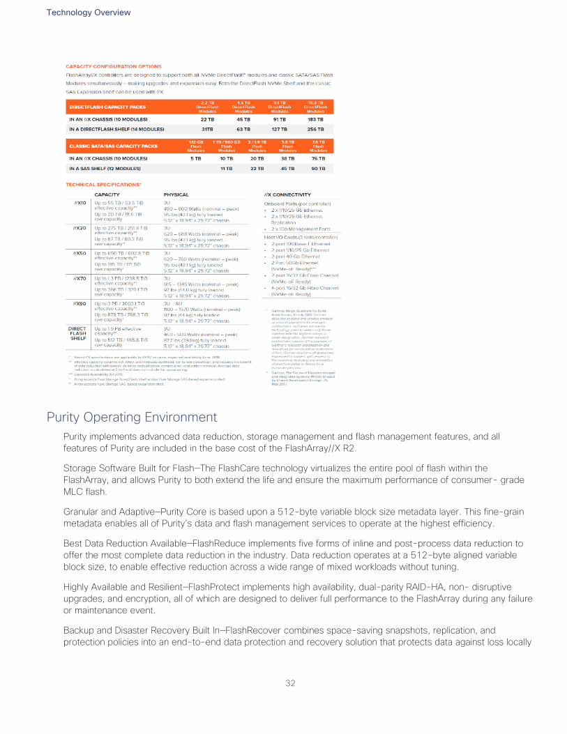
Technology Overview
32
Purity Operating Environment
Purity implements advanced data reduction, storage management and flash management features, and all
features of Purity are included in the base cost of the FlashArray//X R2.
Storage Software Built for Flash—The FlashCare technology virtualizes the entire pool of flash within the
FlashArray, and allows Purity to both extend the life and ensure the maximum performance of consumer- grade
MLC flash.
Granular and Adaptive—Purity Core is based upon a 512-byte variable block size metadata layer. This fine-grain
metadata enables all of Purity’s data and flash management services to operate at the highest efficiency.
Best Data Reduction Available—FlashReduce implements five forms of inline and post-process data reduction to
offer the most complete data reduction in the industry. Data reduction operates at a 512-byte aligned variable
block size, to enable effective reduction across a wide range of mixed workloads without tuning.
Highly Available and Resilient—FlashProtect implements high availability, dual-parity RAID-HA, non- disruptive
upgrades, and encryption, all of which are designed to deliver full performance to the FlashArray during any failure
or maintenance event.
Backup and Disaster Recovery Built In—FlashRecover combines space-saving snapshots, replication, and
protection policies into an end-to-end data protection and recovery solution that protects data against loss locally
Technology Overview
33
and globally. All FlashProtect services are fully-integrated in the FlashArray and leverage the native data reduction
capabilities.
Purity//FA Pure1®
Pure1 Manage—By combining local web-based management with cloud-based monitoring, Pure1 Manage allows
you to manage your FlashArray wherever you are – with just a web browser.
Pure1 Connect—A rich set of APIs, plugin-is, application connectors, and automation toolkits enable you to
connect FlashArray//X R2 to all your data center and cloud monitoring, management, and orchestration tools.
Pure1 Support—FlashArray//X R2 is constantly cloud- connected, enabling Pure Storage to deliver the most
proactive support experience possible. Highly trained staff combined with big data analytics help resolve problems
before they start.
Pure1 Collaborate—Extend your development and support experience online, leveraging the Pure1 Collaborate
community to get peer-based support, and to share tips, tricks, and scripts.
Experience Evergreen™ Storage
Get storage that behaves like SaaS and the cloud. Deploy it once and keep expanding and improving
performance, capacity, density and/or features for 10 years or more – without downtime, performance impact, or
data migrations. Our “Right Size” capacity guarantee ensures you get started knowing you will have the effective
capacity you need. And our Capacity Consolidation program keeps your storage modern and dense as you
expand. With Evergreen Storage, you will never re-buy a TB you already own.
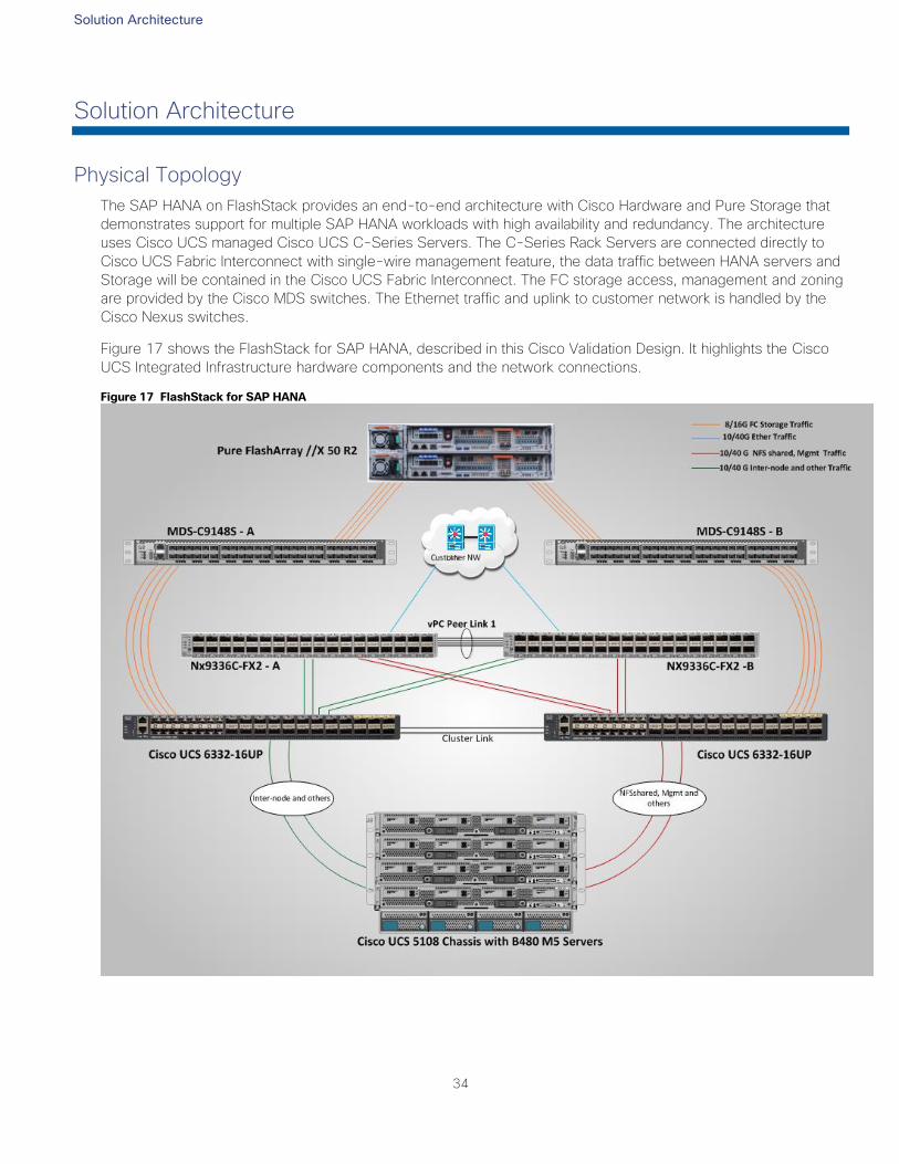
Solution Architecture
34
Solution Architecture
Physical Topology
The SAP HANA on FlashStack provides an end-to-end architecture with Cisco Hardware and Pure Storage that
demonstrates support for multiple SAP HANA workloads with high availability and redundancy. The architecture
uses Cisco UCS managed Cisco UCS C-Series Servers. The C-Series Rack Servers are connected directly to
Cisco UCS Fabric Interconnect with single-wire management feature, the data traffic between HANA servers and
Storage will be contained in the Cisco UCS Fabric Interconnect. The FC storage access, management and zoning
are provided by the Cisco MDS switches. The Ethernet traffic and uplink to customer network is handled by the
Cisco Nexus switches.
Figure 17 shows the FlashStack for SAP HANA, described in this Cisco Validation Design. It highlights the Cisco
UCS Integrated Infrastructure hardware components and the network connections.
Figure 17 FlashStack for SAP HANA
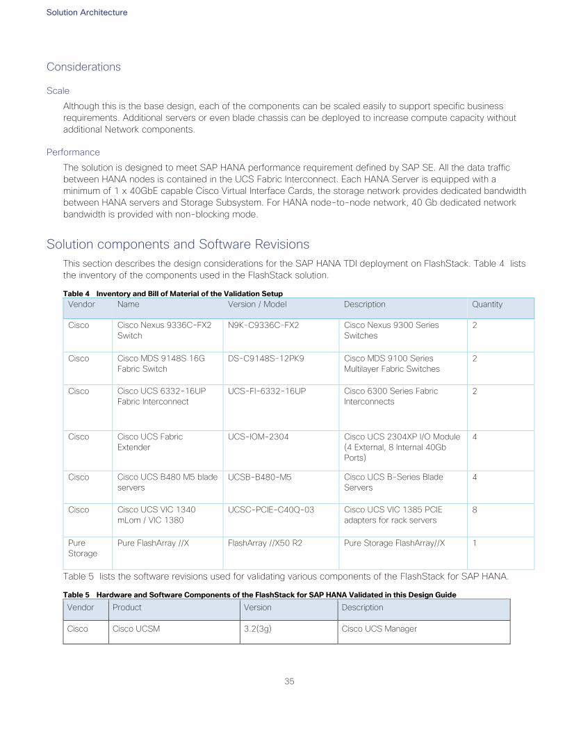
Solution Architecture
35
Considerations
Scale
Although this is the base design, each of the components can be scaled easily to support specific business
requirements. Additional servers or even blade chassis can be deployed to increase compute capacity without
additional Network components.
Performance
The solution is designed to meet SAP HANA performance requirement defined by SAP SE. All the data traffic
between HANA nodes is contained in the UCS Fabric Interconnect. Each HANA Server is equipped with a
minimum of 1 x 40GbE capable Cisco Virtual Interface Cards, the storage network provides dedicated bandwidth
between HANA servers and Storage Subsystem. For HANA node-to-node network, 40 Gb dedicated network
bandwidth is provided with non-blocking mode.
Solution components and Software Revisions
This section describes the design considerations for the SAP HANA TDI deployment on FlashStack. Table 4 lists
the inventory of the components used in the FlashStack solution.
Table 4 Inventory and Bill of Material of the Validation Setup
Vendor Name Version / Model Description Quantity
Cisco Cisco Nexus 9336C-FX2
Switch
N9K-C9336C-FX2 Cisco Nexus 9300 Series
Switches
2
Cisco Cisco MDS 9148S 16G
Fabric Switch
DS-C9148S-12PK9 Cisco MDS 9100 Series
Multilayer Fabric Switches
2
Cisco Cisco UCS 6332-16UP
Fabric Interconnect
UCS-FI-6332-16UP Cisco 6300 Series Fabric
Interconnects
2
Cisco Cisco UCS Fabric
Extender
UCS-IOM-2304 Cisco UCS 2304XP I/O Module
(4 External, 8 Internal 40Gb
Ports)
4
Cisco Cisco UCS B480 M5 blade
servers
UCSB-B480-M5 Cisco UCS B-Series Blade
Servers
4
Cisco Cisco UCS VIC 1340
mLom / VIC 1380
UCSC-PCIE-C40Q-03 Cisco UCS VIC 1385 PCIE
adapters for rack servers
8
Pure
Storage
Pure FlashArray //X FlashArray //X50 R2 Pure Storage FlashArray//X 1
Table 5 lists the software revisions used for validating various components of the FlashStack for SAP HANA.
Table 5 Hardware and Software Components of the FlashStack for SAP HANA Validated in this Design Guide
Vendor Product Version Description
Cisco Cisco UCSM 3.2(3g) Cisco UCS Manager
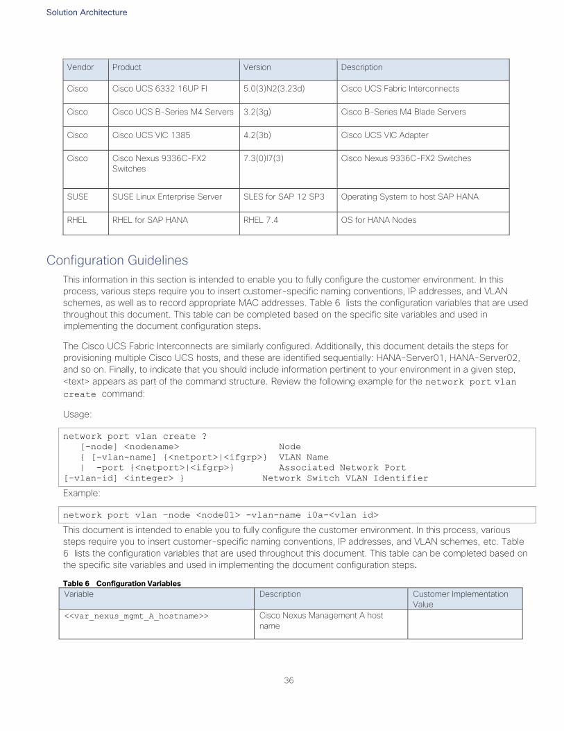
Solution Architecture
36
Vendor Product Version Description
Cisco Cisco UCS 6332 16UP FI 5.0(3)N2(3.23d) Cisco UCS Fabric Interconnects
Cisco Cisco UCS B-Series M4 Servers 3.2(3g) Cisco B-Series M4 Blade Servers
Cisco Cisco UCS VIC 1385 4.2(3b) Cisco UCS VIC Adapter
Cisco Cisco Nexus 9336C-FX2
Switches
7.3(0)I7(3) Cisco Nexus 9336C-FX2 Switches
SUSE SUSE Linux Enterprise Server SLES for SAP 12 SP3 Operating System to host SAP HANA
RHEL RHEL for SAP HANA RHEL 7.4 OS for HANA Nodes
Configuration Guidelines
This information in this section is intended to enable you to fully configure the customer environment. In this
process, various steps require you to insert customer-specific naming conventions, IP addresses, and VLAN
schemes, as well as to record appropriate MAC addresses. Table 6 lists the configuration variables that are used
throughout this document. This table can be completed based on the specific site variables and used in
implementing the document configuration steps.
The Cisco UCS Fabric Interconnects are similarly configured. Additionally, this document details the steps for
provisioning multiple Cisco UCS hosts, and these are identified sequentially: HANA-Server01, HANA-Server02,
and so on. Finally, to indicate that you should include information pertinent to your environment in a given step,
<text> appears as part of the command structure. Review the following example for the network port vlan
create command:
Usage:
network port vlan create ?
[-node] <nodename> Node
{ [-vlan-name] {<netport>|<ifgrp>} VLAN Name
| -port {<netport>|<ifgrp>} Associated Network Port
[-vlan-id] <integer> } Network Switch VLAN Identifier
Example:
network port vlan –node <node01> -vlan-name i0a-<vlan id>
This document is intended to enable you to fully configure the customer environment. In this process, various
steps require you to insert customer-specific naming conventions, IP addresses, and VLAN schemes, etc. Table
6 lists the configuration variables that are used throughout this document. This table can be completed based on
the specific site variables and used in implementing the document configuration steps.
Table 6 Configuration Variables
Variable Description Customer Implementation
Value
<<var_nexus_mgmt_A_hostname>> Cisco Nexus Management A host
name
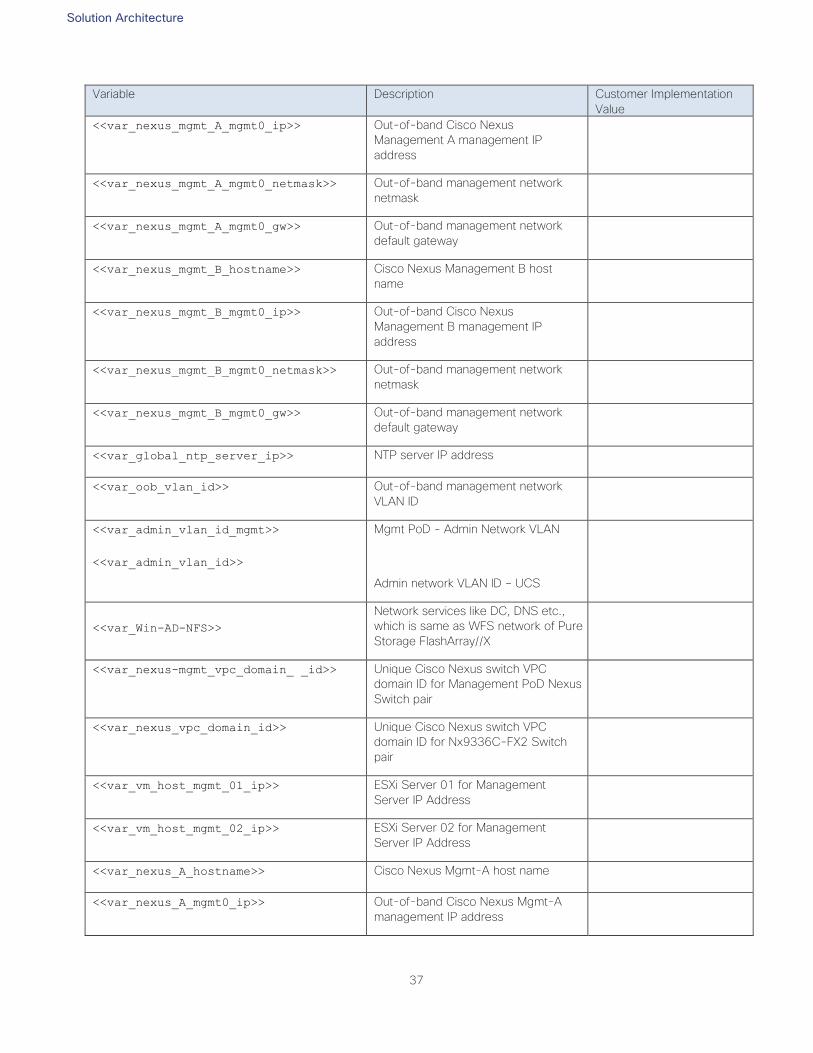
Solution Architecture
37
Variable Description Customer Implementation
Value
<<var_nexus_mgmt_A_mgmt0_ip>> Out-of-band Cisco Nexus
Management A management IP
address
<<var_nexus_mgmt_A_mgmt0_netmask>> Out-of-band management network
netmask
<<var_nexus_mgmt_A_mgmt0_gw>> Out-of-band management network
default gateway
<<var_nexus_mgmt_B_hostname>> Cisco Nexus Management B host
name
<<var_nexus_mgmt_B_mgmt0_ip>> Out-of-band Cisco Nexus
Management B management IP
address
<<var_nexus_mgmt_B_mgmt0_netmask>> Out-of-band management network
netmask
<<var_nexus_mgmt_B_mgmt0_gw>> Out-of-band management network
default gateway
<<var_global_ntp_server_ip>> NTP server IP address
<<var_oob_vlan_id>> Out-of-band management network
VLAN ID
<<var_admin_vlan_id_mgmt>>
<<var_admin_vlan_id>>
Mgmt PoD - Admin Network VLAN
Admin network VLAN ID – UCS
<<var_Win-AD-NFS>>
Network services like DC, DNS etc.,
which is same as WFS network of Pure
Storage FlashArray//X
<<var_nexus-mgmt_vpc_domain_ _id>> Unique Cisco Nexus switch VPC
domain ID for Management PoD Nexus
Switch pair
<<var_nexus_vpc_domain_id>> Unique Cisco Nexus switch VPC
domain ID for Nx9336C-FX2 Switch
pair
<<var_vm_host_mgmt_01_ip>> ESXi Server 01 for Management
Server IP Address
<<var_vm_host_mgmt_02_ip>> ESXi Server 02 for Management
Server IP Address
<<var_nexus_A_hostname>> Cisco Nexus Mgmt-A host name
<<var_nexus_A_mgmt0_ip>> Out-of-band Cisco Nexus Mgmt-A
management IP address
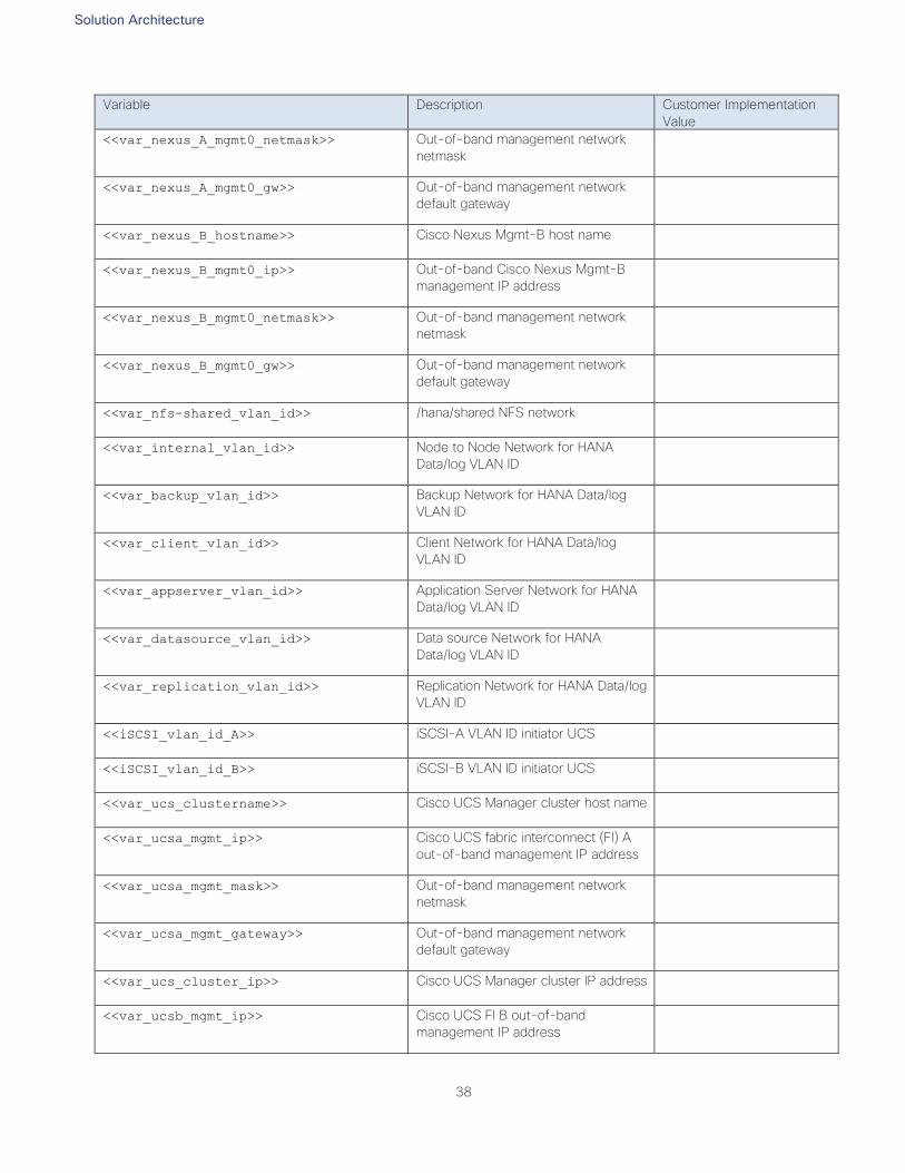
Solution Architecture
38
Variable Description Customer Implementation
Value
<<var_nexus_A_mgmt0_netmask>> Out-of-band management network
netmask
<<var_nexus_A_mgmt0_gw>> Out-of-band management network
default gateway
<<var_nexus_B_hostname>> Cisco Nexus Mgmt-B host name
<<var_nexus_B_mgmt0_ip>> Out-of-band Cisco Nexus Mgmt-B
management IP address
<<var_nexus_B_mgmt0_netmask>> Out-of-band management network
netmask
<<var_nexus_B_mgmt0_gw>> Out-of-band management network
default gateway
<<var_nfs-shared_vlan_id>> /hana/shared NFS network
<<var_internal_vlan_id>> Node to Node Network for HANA
Data/log VLAN ID
<<var_backup_vlan_id>> Backup Network for HANA Data/log
VLAN ID
<<var_client_vlan_id>> Client Network for HANA Data/log
VLAN ID
<<var_appserver_vlan_id>> Application Server Network for HANA
Data/log VLAN ID
<<var_datasource_vlan_id>> Data source Network for HANA
Data/log VLAN ID
<<var_replication_vlan_id>> Replication Network for HANA Data/log
VLAN ID
<<iSCSI_vlan_id_A>> iSCSI-A VLAN ID initiator UCS
<<iSCSI_vlan_id_B>> iSCSI-B VLAN ID initiator UCS
<<var_ucs_clustername>> Cisco UCS Manager cluster host name
<<var_ucsa_mgmt_ip>> Cisco UCS fabric interconnect (FI) A
out-of-band management IP address
<<var_ucsa_mgmt_mask>> Out-of-band management network
netmask
<<var_ucsa_mgmt_gateway>> Out-of-band management network
default gateway
<<var_ucs_cluster_ip>> Cisco UCS Manager cluster IP address
<<var_ucsb_mgmt_ip>> Cisco UCS FI B out-of-band
management IP address
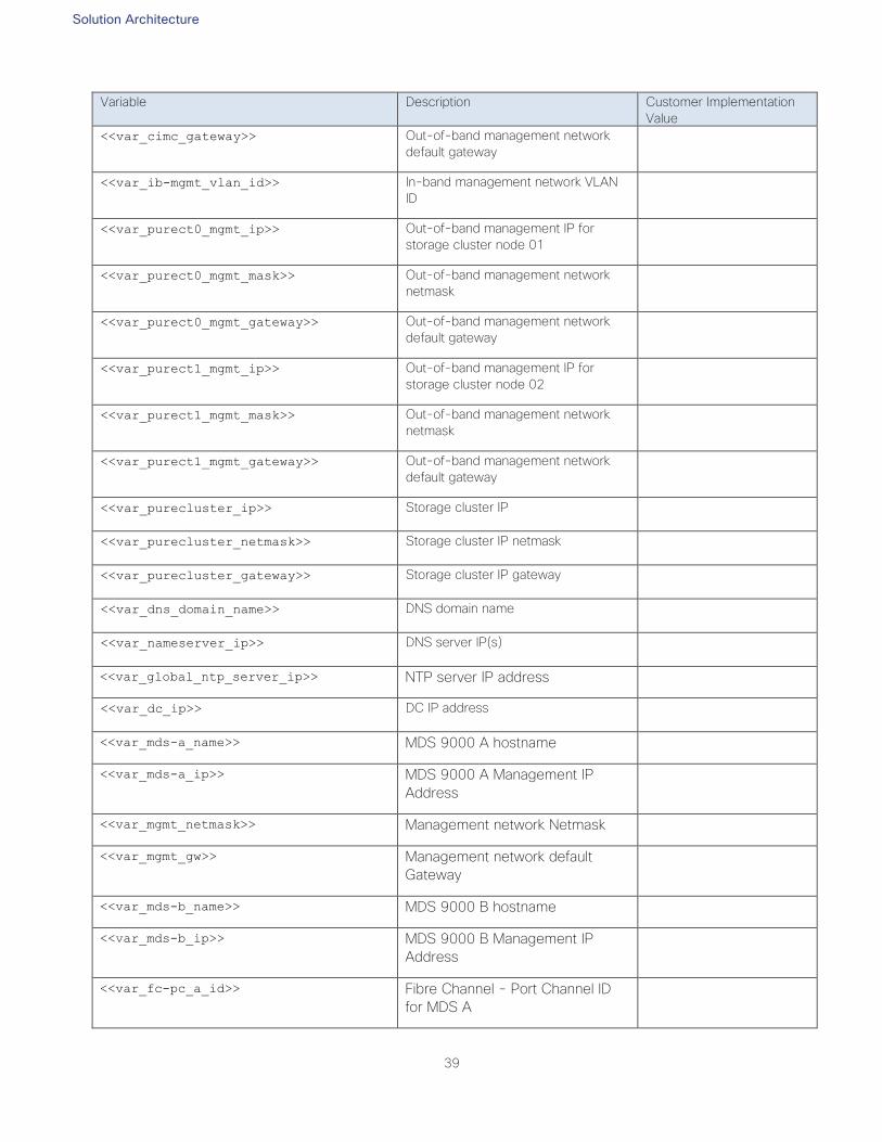
Solution Architecture
39
Variable Description Customer Implementation
Value
<<var_cimc_gateway>> Out-of-band management network
default gateway
<<var_ib-mgmt_vlan_id>> In-band management network VLAN
ID
<<var_purect0_mgmt_ip>> Out-of-band management IP for
storage cluster node 01
<<var_purect0_mgmt_mask>> Out-of-band management network
netmask
<<var_purect0_mgmt_gateway>> Out-of-band management network
default gateway
<<var_purect1_mgmt_ip>> Out-of-band management IP for
storage cluster node 02
<<var_purect1_mgmt_mask>> Out-of-band management network
netmask
<<var_purect1_mgmt_gateway>> Out-of-band management network
default gateway
<<var_purecluster_ip>> Storage cluster IP
<<var_purecluster_netmask>> Storage cluster IP netmask
<<var_purecluster_gateway>> Storage cluster IP gateway
<<var_dns_domain_name>> DNS domain name
<<var_nameserver_ip>> DNS server IP(s)
<<var_global_ntp_server_ip>> NTP server IP address
<<var_dc_ip>> DC IP address
<<var_mds-a_name>> MDS 9000 A hostname
<<var_mds-a_ip>> MDS 9000 A Management IP
Address
<<var_mgmt_netmask>> Management network Netmask
<<var_mgmt_gw>> Management network default
Gateway
<<var_mds-b_name>> MDS 9000 B hostname
<<var_mds-b_ip>> MDS 9000 B Management IP
Address
<<var_fc-pc_a_id>> Fibre Channel - Port Channel ID
for MDS A

Solution Architecture
40
Variable Description Customer Implementation
Value
<<var_fc-pc_b_id>> Fibre Channel - Port Channel ID
for MDS A
<<var_san_a_id>> VSAN ID for MDS A
<<var_san_b_id>> VSAN ID for MDS B
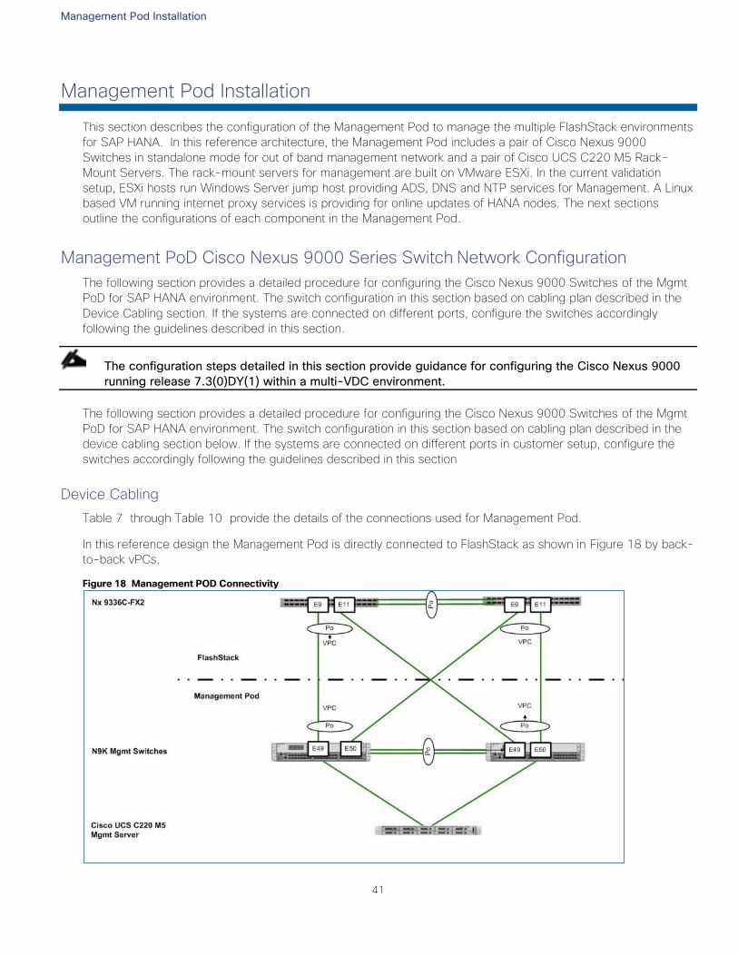
Management Pod Installation
41
Management Pod Installation
This section describes the configuration of the Management Pod to manage the multiple FlashStack environments
for SAP HANA. In this reference architecture, the Management Pod includes a pair of Cisco Nexus 9000
Switches in standalone mode for out of band management network and a pair of Cisco UCS C220 M5 Rack-
Mount Servers. The rack-mount servers for management are built on VMware ESXi. In the current validation
setup, ESXi hosts run Windows Server jump host providing ADS, DNS and NTP services for Management. A Linux
based VM running internet proxy services is providing for online updates of HANA nodes. The next sections
outline the configurations of each component in the Management Pod.
Management PoD Cisco Nexus 9000 Series Switch Network Configuration
The following section provides a detailed procedure for configuring the Cisco Nexus 9000 Switches of the Mgmt
PoD for SAP HANA environment. The switch configuration in this section based on cabling plan described in the
Device Cabling section. If the systems are connected on different ports, configure the switches accordingly
following the guidelines described in this section.
The configuration steps detailed in this section provide guidance for configuring the Cisco Nexus 9000
running release 7.3(0)DY(1) within a multi-VDC environment.
The following section provides a detailed procedure for configuring the Cisco Nexus 9000 Switches of the Mgmt
PoD for SAP HANA environment. The switch configuration in this section based on cabling plan described in the
device cabling section below. If the systems are connected on different ports in customer setup, configure the
switches accordingly following the guidelines described in this section
Device Cabling
Table 7 through Table 10 provide the details of the connections used for Management Pod.
In this reference design the Management Pod is directly connected to FlashStack as shown in Figure 18 by back-
to-back vPCs.
Figure 18 Management POD Connectivity
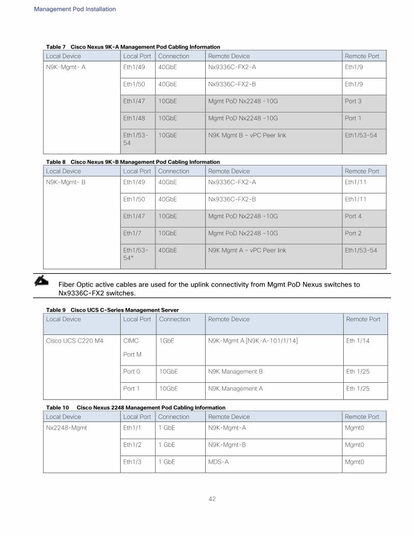
Management Pod Installation
42
Table 7 Cisco Nexus 9K-A Management Pod Cabling Information
Local Device Local Port Connection Remote Device Remote Port
N9K-Mgmt- A
Eth1/49 40GbE Nx9336C-FX2-A Eth1/9
Eth1/50 40GbE Nx9336C-FX2-B Eth1/9
Eth1/47 10GbE Mgmt PoD Nx2248 -10G Port 3
Eth1/48 10GbE Mgmt PoD Nx2248 -10G Port 1
Eth1/53-
54
10GbE N9K Mgmt B – vPC Peer link Eth1/53-54
Table 8 Cisco Nexus 9K-B Management Pod Cabling Information
Local Device Local Port Connection Remote Device Remote Port
N9K-Mgmt- B
Eth1/49 40GbE Nx9336C-FX2-A Eth1/11
Eth1/50 40GbE Nx9336C-FX2-B Eth1/11
Eth1/47 10GbE Mgmt PoD Nx2248 -10G Port 4
Eth1/7 10GbE Mgmt PoD Nx2248 -10G Port 2
Eth1/53-
54*
40GbE N9K Mgmt A – vPC Peer link Eth1/53-54
Fiber Optic active cables are used for the uplink connectivity from Mgmt PoD Nexus switches to
Nx9336C-FX2 switches.
Table 9 Cisco UCS C-Series Management Server
Local Device Local Port Connection Remote Device Remote Port
Cisco UCS C220 M4
CIMC
Port M
1GbE N9K-Mgmt A [N9K-A-101/1/14] Eth 1/14
Port 0 10GbE N9K Management B Eth 1/25
Port 1 10GbE N9K Management A Eth 1/25
Table 10 Cisco Nexus 2248 Management Pod Cabling Information
Local Device Local Port Connection Remote Device Remote Port
Nx2248-Mgmt
Eth1/1 1 GbE N9K-Mgmt-A Mgmt0
Eth1/2 1 GbE N9K-Mgmt-B Mgmt0
Eth1/3 1 GbE MDS-A Mgmt0
Management Pod Installation
43
Local Device Local Port Connection Remote Device Remote Port
Eth1/4 1 GbE MDS-B Mgmt0
Eth1/5 1 GbE FI-A Mgmt0
Eth1/6 1 GbE FI-B Mgmt0
Eth1/7 1 GbE Pure Storage FlashArray//XCT0 Mgmt0
Eth1/8 1 GbE Pure Storage FlashArray//X CT1 Mgmt0
Eth/123 1 GbE Nx9336C-FX2-A Mgmt0
Eth1/24 1 GbE Nx9336C-FX2-B Mgmt0
The configuration steps detailed in this section provides guidance for configuring the Cisco Nexus 9000
running release 7.3(0)DY(1) within a multi-VDC environment.
These steps provide the details for the initial Cisco Nexus 9000 Series Switch setup.
Cisco Nexus 9000 Series Switches ─ Network Initial Configuration Setup
This section provides the steps for the initial Cisco Nexus 9000 Series Switch setup.
Cisco Nexus 9000 A
To set up the initial configuration for the first Cisco Nexus switch, complete the following steps:
On initial boot and connection to the serial or console port of the switch, the NX-OS setup should auto-
matically start and attempt to enter Power on Auto Provisioning.
---- Basic System Configuration Dialog VDC: 1 ----
This setup utility will guide you through the basic configuration of
the system. Setup configures only enough connectivity for management
of the system.
*Note: setup is mainly used for configuring the system initially,
when no configuration is present. So setup always assumes system
defaults and not the current system configuration values.
Press Enter at anytime to skip a dialog. Use ctrl-c at anytime
to skip the remaining dialogs.
Would you like to enter the basic configuration dialog (yes/no): yes
Do you want to enforce secure password standard (yes/no) [y]:
Create another login account (yes/no) [n]:
Configure read-only SNMP community string (yes/no) [n]:
Management Pod Installation
44
Configure read-write SNMP community string (yes/no) [n]:
Enter the switch name : <<var_nexus_mgmt_A_hostname>>
Continue with Out-of-band (mgmt0) management configuration? (yes/no) [y]:
Mgmt0 IPv4 address : <<var_nexus_mgmt_A_mgmt0_ip>>
Mgmt0 IPv4 netmask : <<var_nexus_mgmt_A_mgmt0_netmask>>
Configure the default gateway? (yes/no) [y]:
IPv4 address of the default gateway : <<var_nexus_mgmt_A_mgmt0_gw>>
Configure advanced IP options? (yes/no) [n]:
Enable the telnet service? (yes/no) [n]:
Enable the ssh service? (yes/no) [y]:
Type of ssh key you would like to generate (dsa/rsa) [rsa]:
Number of rsa key bits <1024-2048> [2048]:
Configure the ntp server? (yes/no) [n]: y
NTP server IPv4 address : <<var_global_ntp_server_ip>>
Configure CoPP system profile (strict/moderate/lenient/dense/skip) [strict]:
The following configuration will be applied:
password strength-check
switchname <<var_nexus_mgmt_A_hostname>>
vrf context management
ip route 0.0.0.0/0 <<var_nexus_mgmt_A_mgmt0_gw>>
exit
no feature telnet
ssh key rsa 2048 force
feature ssh
ntp server <<var_global_ntp_server_ip>>
copp profile strict
interface mgmt0
ip address <<var_nexus_mgmt_A_mgmt0_ip>> <<var_nexus_mgmt_A_mgmt0_netmask>>
no shutdown
Would you like to edit the configuration? (yes/no) [n]: Enter
Use this configuration and save it? (yes/no) [y]: Enter
[########################################] 100%
Copy complete.
Cisco Nexus 9000 B
To set up the initial configuration for the second Cisco Nexus switch, complete the following steps:
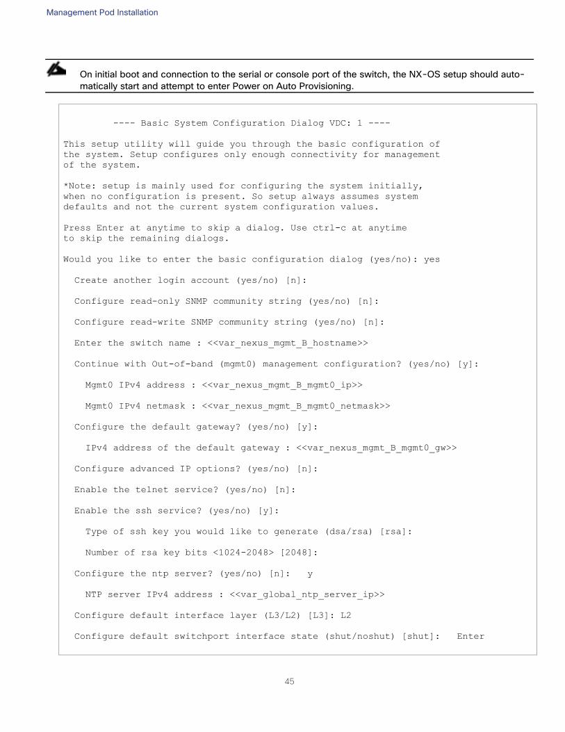
Management Pod Installation
45
On initial boot and connection to the serial or console port of the switch, the NX-OS setup should auto-
matically start and attempt to enter Power on Auto Provisioning.
---- Basic System Configuration Dialog VDC: 1 ----
This setup utility will guide you through the basic configuration of
the system. Setup configures only enough connectivity for management
of the system.
*Note: setup is mainly used for configuring the system initially,
when no configuration is present. So setup always assumes system
defaults and not the current system configuration values.
Press Enter at anytime to skip a dialog. Use ctrl-c at anytime
to skip the remaining dialogs.
Would you like to enter the basic configuration dialog (yes/no): yes
Create another login account (yes/no) [n]:
Configure read-only SNMP community string (yes/no) [n]:
Configure read-write SNMP community string (yes/no) [n]:
Enter the switch name : <<var_nexus_mgmt_B_hostname>>
Continue with Out-of-band (mgmt0) management configuration? (yes/no) [y]:
Mgmt0 IPv4 address : <<var_nexus_mgmt_B_mgmt0_ip>>
Mgmt0 IPv4 netmask : <<var_nexus_mgmt_B_mgmt0_netmask>>
Configure the default gateway? (yes/no) [y]:
IPv4 address of the default gateway : <<var_nexus_mgmt_B_mgmt0_gw>>
Configure advanced IP options? (yes/no) [n]:
Enable the telnet service? (yes/no) [n]:
Enable the ssh service? (yes/no) [y]:
Type of ssh key you would like to generate (dsa/rsa) [rsa]:
Number of rsa key bits <1024-2048> [2048]:
Configure the ntp server? (yes/no) [n]: y
NTP server IPv4 address : <<var_global_ntp_server_ip>>
Configure default interface layer (L3/L2) [L3]: L2
Configure default switchport interface state (shut/noshut) [shut]: Enter
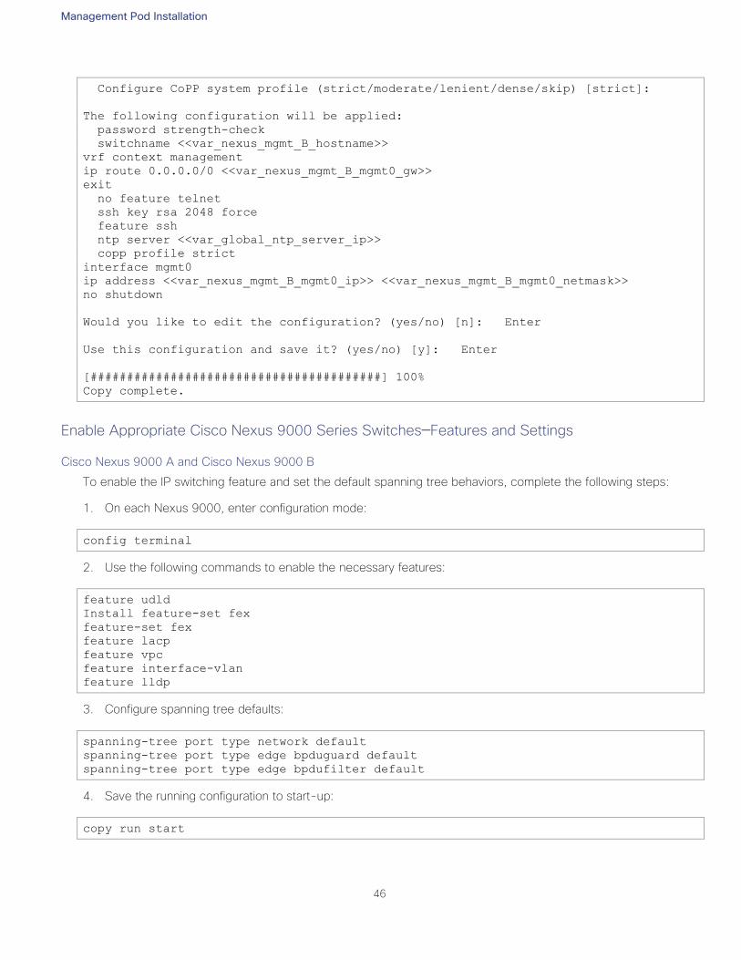
Management Pod Installation
46
Configure CoPP system profile (strict/moderate/lenient/dense/skip) [strict]:
The following configuration will be applied:
password strength-check
switchname <<var_nexus_mgmt_B_hostname>>
vrf context management
ip route 0.0.0.0/0 <<var_nexus_mgmt_B_mgmt0_gw>>
exit
no feature telnet
ssh key rsa 2048 force
feature ssh
ntp server <<var_global_ntp_server_ip>>
copp profile strict
interface mgmt0
ip address <<var_nexus_mgmt_B_mgmt0_ip>> <<var_nexus_mgmt_B_mgmt0_netmask>>
no shutdown
Would you like to edit the configuration? (yes/no) [n]: Enter
Use this configuration and save it? (yes/no) [y]: Enter
[########################################] 100%
Copy complete.
Enable Appropriate Cisco Nexus 9000 Series Switches─Features and Settings
Cisco Nexus 9000 A and Cisco Nexus 9000 B
To enable the IP switching feature and set the default spanning tree behaviors, complete the following steps:
1. On each Nexus 9000, enter configuration mode:
config terminal
2. Use the following commands to enable the necessary features:
feature udld
Install feature-set fex
feature-set fex
feature lacp
feature vpc
feature interface-vlan
feature lldp
3. Configure spanning tree defaults:
spanning-tree port type network default
spanning-tree port type edge bpduguard default
spanning-tree port type edge bpdufilter default
4. Save the running configuration to start-up:
copy run start
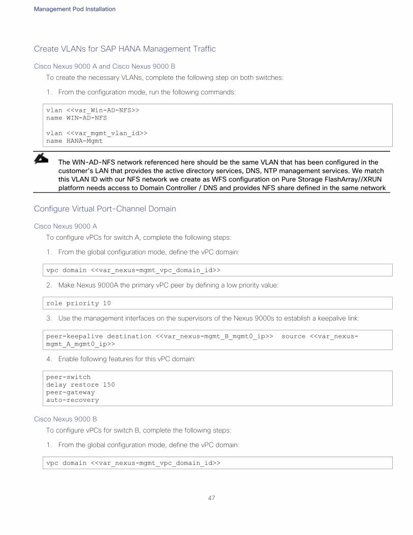
Management Pod Installation
47
Create VLANs for SAP HANA Management Traffic
Cisco Nexus 9000 A and Cisco Nexus 9000 B
To create the necessary VLANs, complete the following step on both switches:
1. From the configuration mode, run the following commands:
vlan <<var_Win-AD-NFS>>
name WIN-AD-NFS
vlan <<var_mgmt_vlan_id>>
name HANA-Mgmt
The WIN-AD-NFS network referenced here should be the same VLAN that has been configured in the
customer’s LAN that provides the active directory services, DNS, NTP management services. We match
this VLAN ID with our NFS network we create as WFS configuration on Pure Storage FlashArray//XRUN
platform needs access to Domain Controller / DNS and provides NFS share defined in the same network
Configure Virtual Port-Channel Domain
Cisco Nexus 9000 A
To configure vPCs for switch A, complete the following steps:
1. From the global configuration mode, define the vPC domain:
vpc domain <<var_nexus-mgmt_vpc_domain_id>>
2. Make Nexus 9000A the primary vPC peer by defining a low priority value:
role priority 10
3. Use the management interfaces on the supervisors of the Nexus 9000s to establish a keepalive link:
peer-keepalive destination <<var_nexus-mgmt_B_mgmt0_ip>> source <<var_nexus-
mgmt_A_mgmt0_ip>>
4. Enable following features for this vPC domain:
peer-switch
delay restore 150
peer-gateway
auto-recovery
Cisco Nexus 9000 B
To configure vPCs for switch B, complete the following steps:
1. From the global configuration mode, define the vPC domain:
vpc domain <<var_nexus-mgmt_vpc_domain_id>>
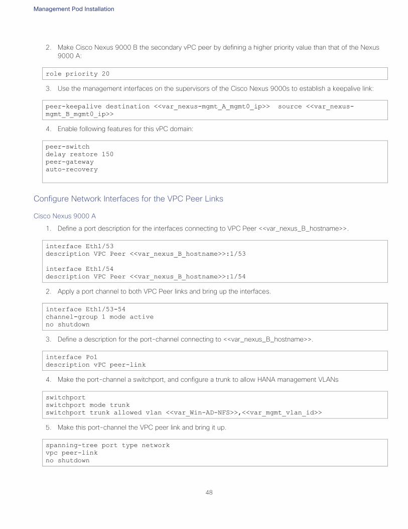
Management Pod Installation
48
2. Make Cisco Nexus 9000 B the secondary vPC peer by defining a higher priority value than that of the Nexus
9000 A:
role priority 20
3. Use the management interfaces on the supervisors of the Cisco Nexus 9000s to establish a keepalive link:
peer-keepalive destination <<var_nexus-mgmt_A_mgmt0_ip>> source <<var_nexus-
mgmt_B_mgmt0_ip>>
4. Enable following features for this vPC domain:
peer-switch
delay restore 150
peer-gateway
auto-recovery
Configure Network Interfaces for the VPC Peer Links
Cisco Nexus 9000 A
1. Define a port description for the interfaces connecting to VPC Peer <<var_nexus_B_hostname>>.
interface Eth1/53
description VPC Peer <<var_nexus_B_hostname>>:1/53
interface Eth1/54
description VPC Peer <<var_nexus_B_hostname>>:1/54
2. Apply a port channel to both VPC Peer links and bring up the interfaces.
interface Eth1/53-54
channel-group 1 mode active
no shutdown
3. Define a description for the port-channel connecting to <<var_nexus_B_hostname>>.
interface Po1
description vPC peer-link
4. Make the port-channel a switchport, and configure a trunk to allow HANA management VLANs
switchport
switchport mode trunk
switchport trunk allowed vlan <<var_Win-AD-NFS>>,<<var_mgmt_vlan_id>>
5. Make this port-channel the VPC peer link and bring it up.
spanning-tree port type network
vpc peer-link
no shutdown
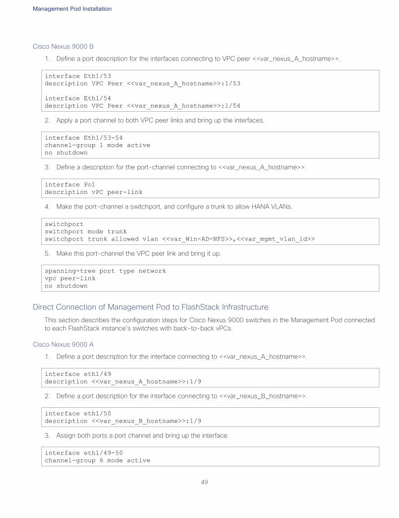
Management Pod Installation
49
Cisco Nexus 9000 B
1. Define a port description for the interfaces connecting to VPC peer <<var_nexus_A_hostname>>.
interface Eth1/53
description VPC Peer <<var_nexus_A_hostname>>:1/53
interface Eth1/54
description VPC Peer <<var_nexus_A_hostname>>:1/54
2. Apply a port channel to both VPC peer links and bring up the interfaces.
interface Eth1/53-54
channel-group 1 mode active
no shutdown
3. Define a description for the port-channel connecting to <<var_nexus_A_hostname>>.
interface Po1
description vPC peer-link
4. Make the port-channel a switchport, and configure a trunk to allow HANA VLANs.
switchport
switchport mode trunk
switchport trunk allowed vlan <<var_Win-AD-NFS>>,<<var_mgmt_vlan_id>>
5. Make this port-channel the VPC peer link and bring it up.
spanning-tree port type network
vpc peer-link
no shutdown
Direct Connection of Management Pod to FlashStack Infrastructure
This section describes the configuration steps for Cisco Nexus 9000 switches in the Management Pod connected
to each FlashStack instance’s switches with back-to-back vPCs.
Cisco Nexus 9000 A
1. Define a port description for the interface connecting to <<var_nexus_A_hostname>>.
interface eth1/49
description <<var_nexus_A_hostname>>:1/9
2. Define a port description for the interface connecting to <<var_nexus_B_hostname>>.
interface eth1/50
description <<var_nexus_B_hostname>>:1/9
3. Assign both ports a port channel and bring up the interface.
interface eth1/49-50
channel-group 6 mode active
Management Pod Installation
50
no shutdown
4. Define a description for the port-channel connecting to FlashStack Switch.
interface Po6
description back-to-back-vpc-with-Nx9336C-FX2-pair
5. Make the port-channel a switchport, and configure a trunk to allow all Management VLANs.
switchport
switchport mode trunk
switchport trunk allowed vlan switchport trunk allowed vlan <<var_Win-AD-
NFS>>,<<var_mgmt_vlan_id>>
6. Make the port channel and associated interfaces spanning tree network ports.
spanning-tree port type network
7. Set the MTU to be 9216 to support jumbo frames.
mtu 9216
8. Make this a VPC port-channel and bring it up.
vpc 6
no shutdown
9. Save the running configuration to start-up.
copy run start
Cisco Nexus 9000 B
1. Define a port description for the interface connecting to <<var_nexus_A_hostname>>.
interface eth1/49
description <<var_nexus_A_hostname>>:eth1/11
2. Define a port description for the interface connecting to <<var_nexus_B_hostname>>.
interface eth1/50
description <<var_nexus_B_hostname>>:eth1/11
3. Assign both the interfaces to a port channel and bring up the interface.
interface eth1/49-50
channel-group 6 mode active
no shutdown
4. Define a description for the port-channel connecting to FlashStack Switch.
interface Po6
description back-to-back-vpc-with-Nx9336C-FX2-pair
Management Pod Installation
51
5. Make the port-channel a switchport, and configure a trunk to allow all Management VLANs.
switchport
switchport mode trunk
switchport trunk allowed vlan switchport trunk allowed vlan <<var_Win-AD-
NFS>>,<<var_mgmt_vlan_id>>
6. Make the port channel and associated interfaces spanning tree network ports.
spanning-tree port type network
7. Set the MTU to be 9216 to support jumbo frames.
mtu 9216
8. Make this a VPC port-channel and bring it up.
vpc 6
no shutdown
9. Save the running configuration to start-up.
copy run start
Dual-Homed FEX Topology (Active/Active FEX Topology) for 1 GE Management Access
A Nexus 2248 switch in dual-homed topology with management Nexus 9000 series switches is used for having
the 1GE management access to all elements of the reference infrastructure.
The dual-homed FEX (Active/Active) topology is supported with NX-OS 7.0(3)I5(2) and later using Cisco Nexus
9300 and Nexus 9300-EX Series switches. The following topology shows that each FEX is dual-homed with two
Cisco Nexus 9300 Series switches.
The FEX-fabric interfaces for each FEX are configured as a vPC on both peer switches. The host interfaces on
the FEX appear on both peer switches.
A sample high-level connectivity/configuration is shown below:
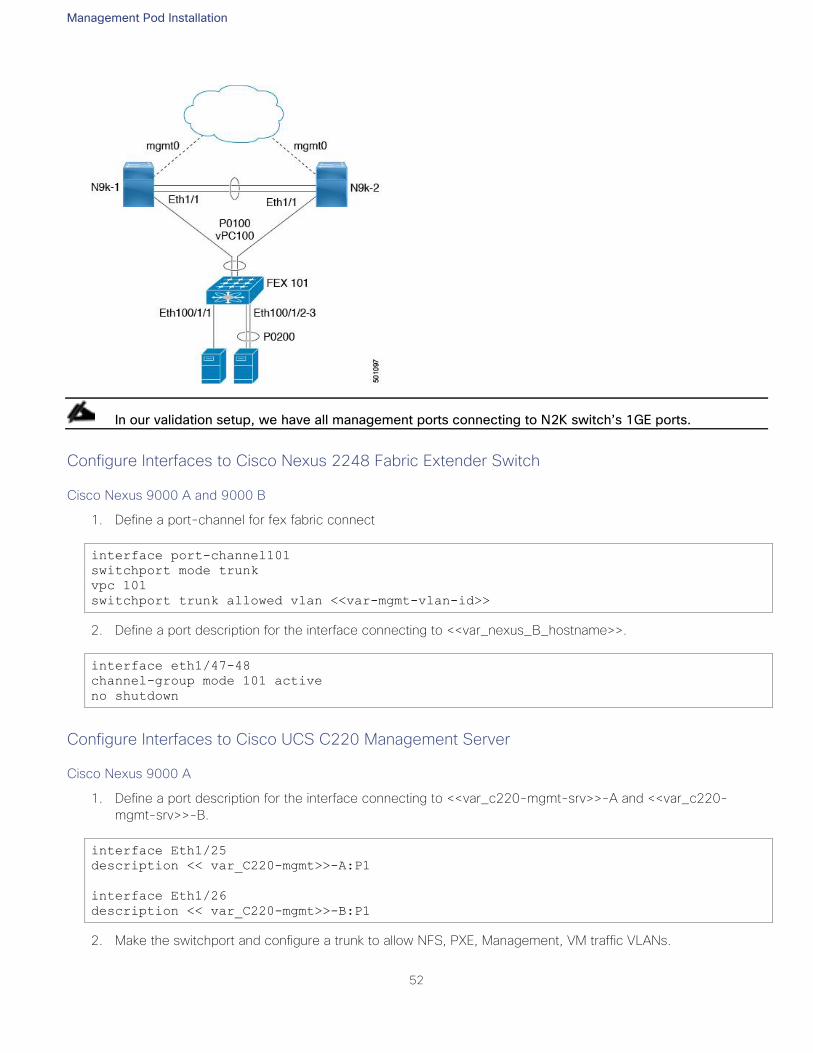
Management Pod Installation
52
In our validation setup, we have all management ports connecting to N2K switch’s 1GE ports.
Configure Interfaces to Cisco Nexus 2248 Fabric Extender Switch
Cisco Nexus 9000 A and 9000 B
1. Define a port-channel for fex fabric connect
interface port-channel101
switchport mode trunk
vpc 101
switchport trunk allowed vlan <<var-mgmt-vlan-id>>
2. Define a port description for the interface connecting to <<var_nexus_B_hostname>>.
interface eth1/47-48
channel-group mode 101 active
no shutdown
Configure Interfaces to Cisco UCS C220 Management Server
Cisco Nexus 9000 A
1. Define a port description for the interface connecting to <<var_c220-mgmt-srv>>-A and <<var_c220-
mgmt-srv>>-B.
interface Eth1/25
description << var_C220-mgmt>>-A:P1
interface Eth1/26
description << var_C220-mgmt>>-B:P1
2. Make the switchport and configure a trunk to allow NFS, PXE, Management, VM traffic VLANs.
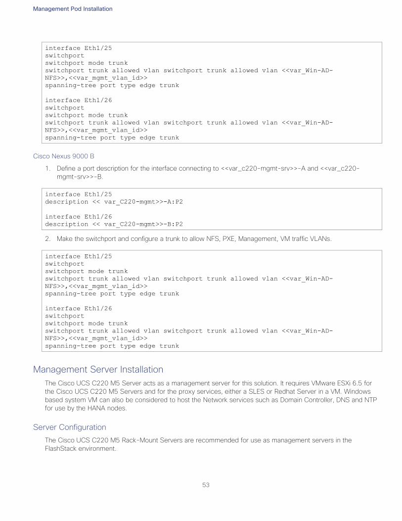
Management Pod Installation
53
interface Eth1/25
switchport
switchport mode trunk
switchport trunk allowed vlan switchport trunk allowed vlan <<var_Win-AD-
NFS>>,<<var_mgmt_vlan_id>>
spanning-tree port type edge trunk
interface Eth1/26
switchport
switchport mode trunk
switchport trunk allowed vlan switchport trunk allowed vlan <<var_Win-AD-
NFS>>,<<var_mgmt_vlan_id>>
spanning-tree port type edge trunk
Cisco Nexus 9000 B
1. Define a port description for the interface connecting to <<var_c220-mgmt-srv>>-A and <<var_c220-
mgmt-srv>>-B.
interface Eth1/25
description << var_C220-mgmt>>-A:P2
interface Eth1/26
description << var_C220-mgmt>>-B:P2
2. Make the switchport and configure a trunk to allow NFS, PXE, Management, VM traffic VLANs.
interface Eth1/25
switchport
switchport mode trunk
switchport trunk allowed vlan switchport trunk allowed vlan <<var_Win-AD-
NFS>>,<<var_mgmt_vlan_id>>
spanning-tree port type edge trunk
interface Eth1/26
switchport
switchport mode trunk
switchport trunk allowed vlan switchport trunk allowed vlan <<var_Win-AD-
NFS>>,<<var_mgmt_vlan_id>>
spanning-tree port type edge trunk
Management Server Installation
The Cisco UCS C220 M5 Server acts as a management server for this solution. It requires VMware ESXi 6.5 for
the Cisco UCS C220 M5 Servers and for the proxy services, either a SLES or Redhat Server in a VM. Windows
based system VM can also be considered to host the Network services such as Domain Controller, DNS and NTP
for use by the HANA nodes.
Server Configuration
The Cisco UCS C220 M5 Rack-Mount Servers are recommended for use as management servers in the
FlashStack environment.
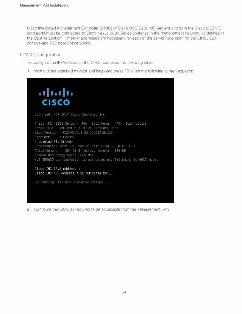
Management Pod Installation
54
Cisco Integrated Management Controller (CIMC) of Cisco UCS C220 M5 Servers and both the Cisco UCS VIC
card ports must be connected to Cisco Nexus 9000 Series Switches in the management network, as defined in
the Cabling Section. Three IP addresses are necessary for each of the server; one each for the CIMC, ESXi
console and PXE boot VM networks.
CIMC Configuration
To configure the IP-Address on the CIMC, complete the following steps:
1. With a direct attached monitor and keyboard press F8 when the following screen appears:
2. Configure the CIMC as required to be accessible from the Management LAN.
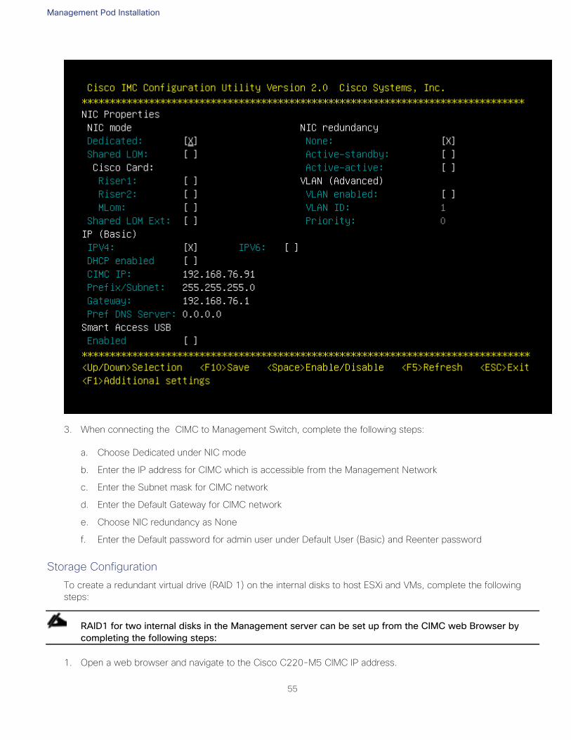
Management Pod Installation
55
3. When connecting the CIMC to Management Switch, complete the following steps:
a. Choose Dedicated under NIC mode
b. Enter the IP address for CIMC which is accessible from the Management Network
c. Enter the Subnet mask for CIMC network
d. Enter the Default Gateway for CIMC network
e. Choose NIC redundancy as None
f. Enter the Default password for admin user under Default User (Basic) and Reenter password
Storage Configuration
To create a redundant virtual drive (RAID 1) on the internal disks to host ESXi and VMs, complete the following
steps:
RAID1 for two internal disks in the Management server can be set up from the CIMC web Browser by
completing the following steps:
1. Open a web browser and navigate to the Cisco C220-M5 CIMC IP address.
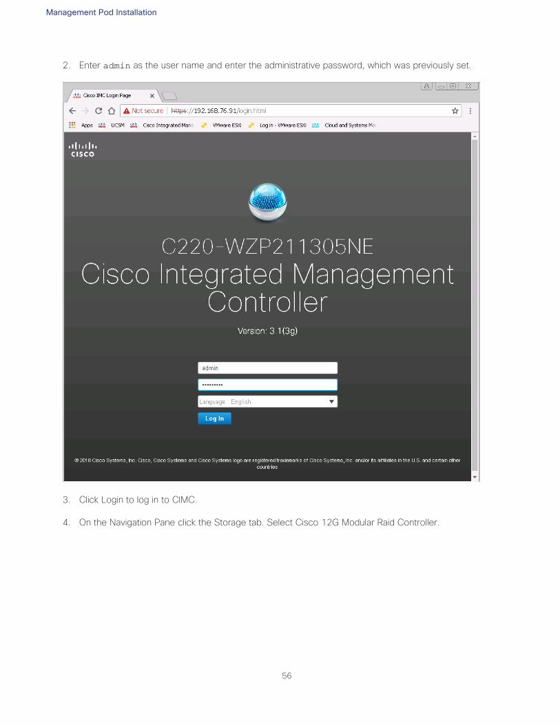
Management Pod Installation
56
2. Enter admin as the user name and enter the administrative password, which was previously set.
3. Click Login to log in to CIMC.
4. On the Navigation Pane click the Storage tab. Select Cisco 12G Modular Raid Controller.
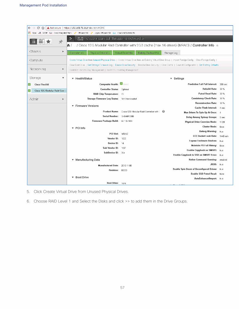
Management Pod Installation
57
5. Click Create Virtual Drive from Unused Physical Drives.
6. Choose RAID Level 1 and Select the Disks and click >> to add them in the Drive Groups.
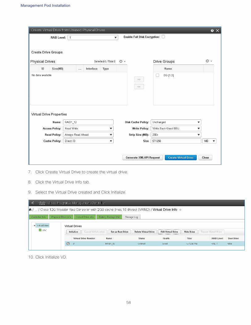
Management Pod Installation
58
7. Click Create Virtual Drive to create the virtual drive.
8. Click the Virtual Drive Info tab.
9. Select the Virtual Drive created and Click Initialize.
10. Click Initialize VD.
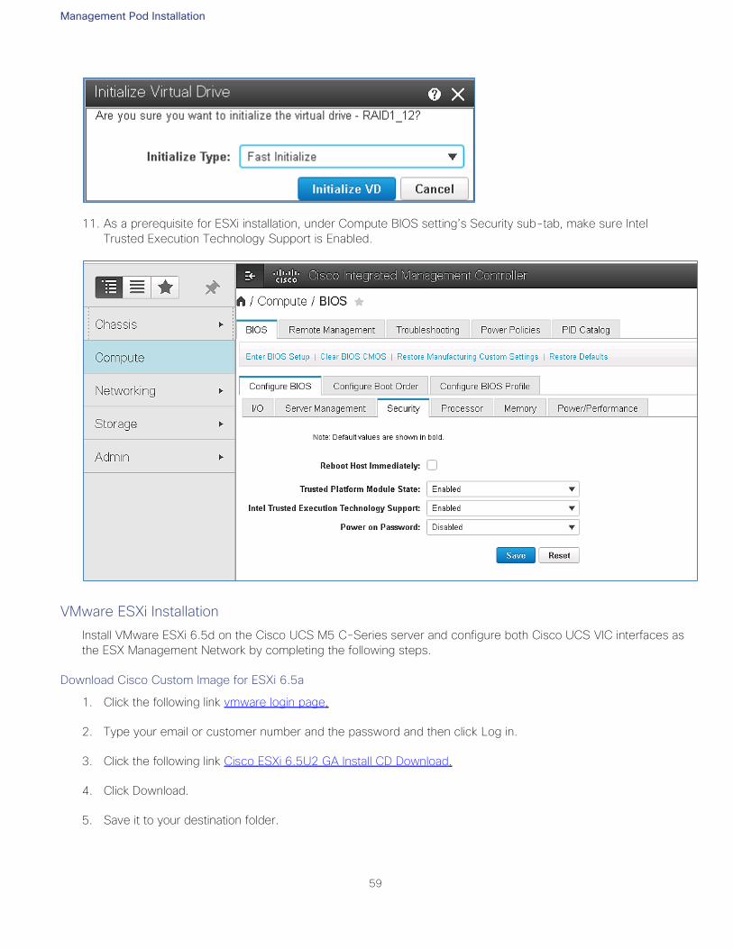
Management Pod Installation
59
11. As a prerequisite for ESXi installation, under Compute BIOS setting’s Security sub-tab, make sure Intel
Trusted Execution Technology Support is Enabled.
VMware ESXi Installation
Install VMware ESXi 6.5d on the Cisco UCS M5 C-Series server and configure both Cisco UCS VIC interfaces as
the ESX Management Network by completing the following steps.
Download Cisco Custom Image for ESXi 6.5a
1. Click the following link vmware login page.
2. Type your email or customer number and the password and then click Log in.
3. Click the following link Cisco ESXi 6.5U2 GA Install CD Download.
4. Click Download.
5. Save it to your destination folder.
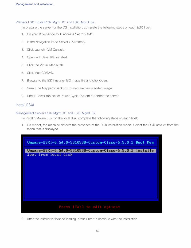
Management Pod Installation
60
VMware ESXi Hosts ESXi-Mgmt-01 and ESXi-Mgmt-02
To prepare the server for the OS installation, complete the following steps on each ESXi host:
1. On your Browser go to IP address Set for CIMC.
2. In the Navigation Pane Server > Summary.
3. Click Launch KVM Console.
4. Open with Java JRE installed.
5. Click the Virtual Media tab.
6. Click Map CD/DVD.
7. Browse to the ESXi installer ISO image file and click Open.
8. Select the Mapped checkbox to map the newly added image.
9. Under Power tab select Power Cycle System to reboot the server.
Install ESXi
Management Server ESXi-Mgmt-01 and ESXi-Mgmt-02
To install VMware ESXi on the local disk, complete the following steps on each host:
1. On reboot, the machine detects the presence of the ESXi installation media. Select the ESXi installer from the
menu that is displayed.
2. After the installer is finished loading, press Enter to continue with the installation.

Management Pod Installation
61
3. Read and accept the end-user license agreement (EULA). Press F11 to accept and continue.
4. Select the local disk which was previously created for ESXi and press Enter to continue with the installation.
5. Select the appropriate keyboard layout and press Enter.
6. Enter and confirm the root password and press Enter.
7. The installer issues a warning that existing partitions will be repartitioned. Press F11 to continue with the in-
stallation.
8. After the installation is complete, clear the Mapped checkbox (located in the Virtual Media tab of the KVM
console) to unmap the ESXi installation image.
9. The ESXi installation image must be unmapped to make sure that the server reboots into ESXi and not into the
installer.
10. The Virtual Media window might issue a warning stating that it is preferable to eject the media from the guest.
Click Yes to unmap the image.
11. From the KVM tab, press Enter to reboot the server.
Set Up Management Networking for ESXi Hosts
Adding a management network for each VMware host is necessary for managing the host. To add a management
network for the VMware hosts, complete the following steps on each ESXi host.
Configure Management Access
To configure the ESXi-Mgmt-01 ESXi host with access to the management network, complete the following
steps:
1. After the server has finished rebooting, press F2 to customize the system.
2. Log in as root and enter the corresponding password.
3. Select the Configure the Management Network option and press Enter.
4. Select the VLAN (Optional) option and press Enter.
5. Enter the <<var_oob_vlan_id>> and press Enter.
6. From the Configure Management Network menu, select IP Configuration and press Enter.
7. Select the Set Static IP Address and Network Configuration option by using the space bar.
8. Enter the IP address for managing the first ESXi host: <<var_vm_host_mgmt_01_ip>>.
9. Enter the subnet mask for the first ESXi host.
10. Enter the default gateway for the first ESXi host.
11. Press Enter to accept the changes to the IP configuration.

Management Pod Installation
62
12. Select the IPv6 Configuration option and press Enter.
13. Using the spacebar, unselect Enable IPv6 (restart required) and press Enter.
14. Select the DNS Configuration option and press Enter.
15. Because the IP address is assigned manually, the DNS information must also be entered manually.
16. Enter the IP address of the primary DNS server.
17. Optional: Enter the IP address of the secondary DNS server.
18. Enter the fully qualified domain name (FQDN) for the first ESXi host.
19. Press Enter to accept the changes to the DNS configuration.
20. Press Esc to exit the Configure Management Network submenu.
21. Press Y to confirm the changes and return to the main menu.
22. The ESXi host reboots. After reboot, press F2 and log back in as root.
23. Select Test Management Network to verify that the management network is set up correctly and press Enter.
24. Press Enter to run the test.
25. Press Enter to exit the window.
26. Press Esc to log out of the VMware console.
Repeat the above steps to configure the ESXi-Mgmt-02 ESXi host.
VMware ESXi Host ESXi-Mgmt-01
Set Up VMkernel Ports and Virtual Switch
Repeat the steps in this section for all the ESXi Hosts.
To set up the VMkernel ports and the virtual switches on the ESXi-Mgmt-01 ESXi host, complete the following
steps:
1. From each Web client, select the host in the inventory.
2. Click the Networking in the main pane.
3. Select Standard Switch: vSwith0
4. Select Network Adapters tab and add vmnic2 and vmnic3 to the vSwitch and click Save.
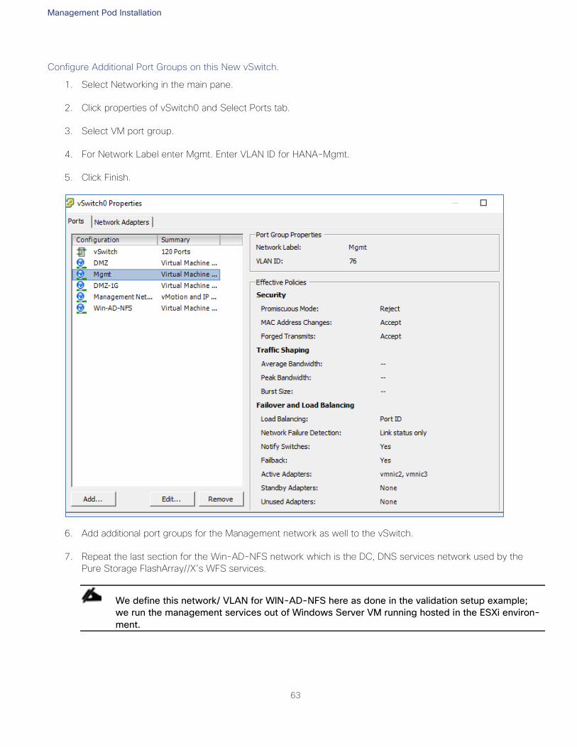
Management Pod Installation
63
Configure Additional Port Groups on this New vSwitch.
1. Select Networking in the main pane.
2. Click properties of vSwitch0 and Select Ports tab.
3. Select VM port group.
4. For Network Label enter Mgmt. Enter VLAN ID for HANA-Mgmt.
5. Click Finish.
6. Add additional port groups for the Management network as well to the vSwitch.
7. Repeat the last section for the Win-AD-NFS network which is the DC, DNS services network used by the
Pure Storage FlashArray//X’s WFS services.
We define this network/ VLAN for WIN-AD-NFS here as done in the validation setup example;
we run the management services out of Windows Server VM running hosted in the ESXi environ-
ment.
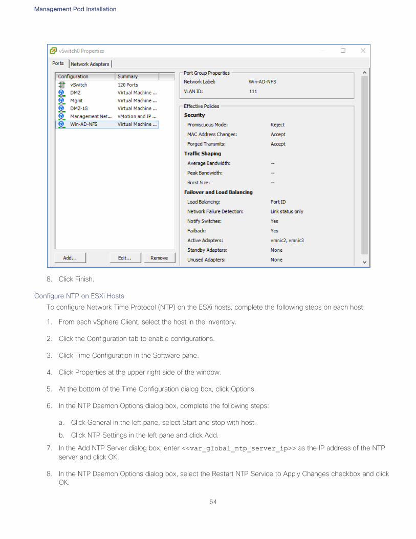
Management Pod Installation
64
8. Click Finish.
Configure NTP on ESXi Hosts
To configure Network Time Protocol (NTP) on the ESXi hosts, complete the following steps on each host:
1. From each vSphere Client, select the host in the inventory.
2. Click the Configuration tab to enable configurations.
3. Click Time Configuration in the Software pane.
4. Click Properties at the upper right side of the window.
5. At the bottom of the Time Configuration dialog box, click Options.
6. In the NTP Daemon Options dialog box, complete the following steps:
a. Click General in the left pane, select Start and stop with host.
b. Click NTP Settings in the left pane and click Add.
7. In the Add NTP Server dialog box, enter <<var_global_ntp_server_ip>> as the IP address of the NTP
server and click OK.
8. In the NTP Daemon Options dialog box, select the Restart NTP Service to Apply Changes checkbox and click
OK.

Management Pod Installation
65
9. In the Time Configuration dialog box, complete the following steps:
a. Select the NTP Client Enabled checkbox and click OK.
b. Verify that the clock is now set to approximately the correct time.
10. The NTP server time may vary slightly from the host time.
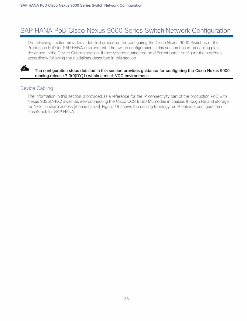
SAP HANA PoD Cisco Nexus 9000 Series Switch Network Configuration
66
SAP HANA PoD Cisco Nexus 9000 Series Switch Network Configuration
The following section provides a detailed procedure for configuring the Cisco Nexus 9000 Switches of the
Production PoD for SAP HANA environment. The switch configuration in this section based on cabling plan
described in the Device Cabling section. If the systems connected on different ports, configure the switches
accordingly following the guidelines described in this section
The configuration steps detailed in this section provides guidance for configuring the Cisco Nexus 9000
running release 7.3(0)DY(1) within a multi-VDC environment.
Device Cabling
The information in this section is provided as a reference for the IP connectivity part of the production PoD with
Nexus 9336C-FX2 switches interconnecting the Cisco UCS B480 M5 nodes in chassis through FIs and storage
for NFS file share access [/hana/shared]. Figure 19 shows the cabling topology for IP network configuration of
FlashStack for SAP HANA.
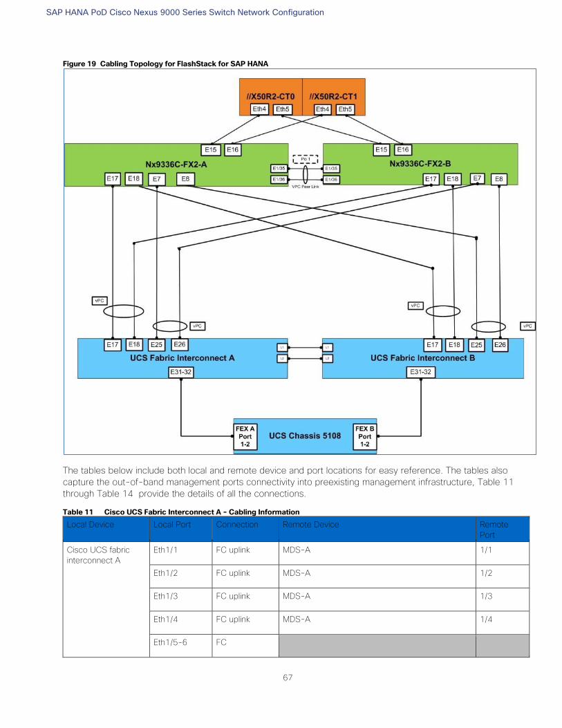
SAP HANA PoD Cisco Nexus 9000 Series Switch Network Configuration
67
Figure 19 Cabling Topology for FlashStack for SAP HANA
The tables below include both local and remote device and port locations for easy reference. The tables also
capture the out-of-band management ports connectivity into preexisting management infrastructure, Table 11
through Table 14 provide the details of all the connections.
Table 11 Cisco UCS Fabric Interconnect A - Cabling Information
Local Device Local Port Connection Remote Device Remote
Port
Cisco UCS fabric
interconnect A
Eth1/1 FC uplink MDS-A 1/1
Eth1/2 FC uplink MDS-A 1/2
Eth1/3 FC uplink MDS-A 1/3
Eth1/4 FC uplink MDS-A 1/4
Eth1/5-6 FC
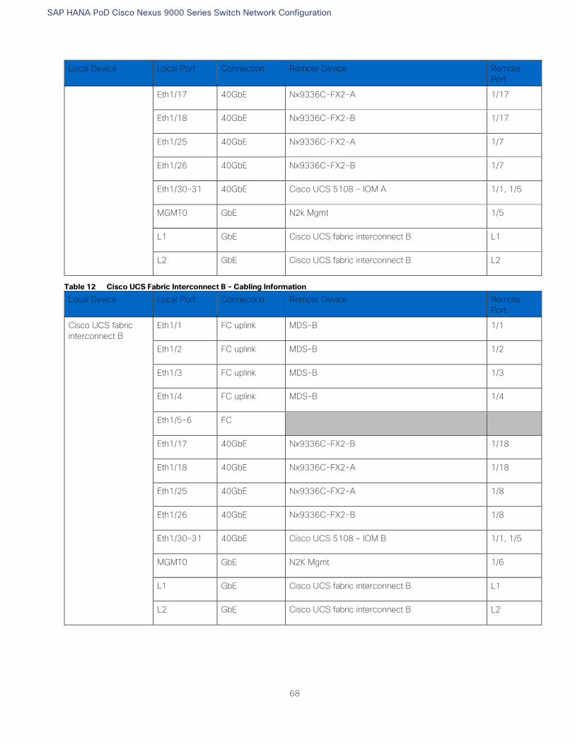
SAP HANA PoD Cisco Nexus 9000 Series Switch Network Configuration
68
Local Device Local Port Connection Remote Device Remote
Port
Eth1/17 40GbE Nx9336C-FX2-A 1/17
Eth1/18 40GbE Nx9336C-FX2-B 1/17
Eth1/25 40GbE Nx9336C-FX2-A 1/7
Eth1/26 40GbE Nx9336C-FX2-B 1/7
Eth1/30-31 40GbE Cisco UCS 5108 – IOM A 1/1, 1/5
MGMT0 GbE N2k Mgmt 1/5
L1 GbE Cisco UCS fabric interconnect B L1
L2 GbE Cisco UCS fabric interconnect B L2
Table 12 Cisco UCS Fabric Interconnect B - Cabling Information
Local Device Local Port Connection Remote Device Remote
Port
Cisco UCS fabric
interconnect B
Eth1/1 FC uplink MDS-B 1/1
Eth1/2 FC uplink MDS-B 1/2
Eth1/3 FC uplink MDS-B 1/3
Eth1/4 FC uplink MDS-B 1/4
Eth1/5-6 FC
Eth1/17 40GbE Nx9336C-FX2-B 1/18
Eth1/18 40GbE Nx9336C-FX2-A 1/18
Eth1/25 40GbE Nx9336C-FX2-A 1/8
Eth1/26 40GbE Nx9336C-FX2-B 1/8
Eth1/30-31 40GbE Cisco UCS 5108 – IOM B 1/1, 1/5
MGMT0 GbE N2K Mgmt 1/6
L1 GbE Cisco UCS fabric interconnect B L1
L2 GbE Cisco UCS fabric interconnect B L2
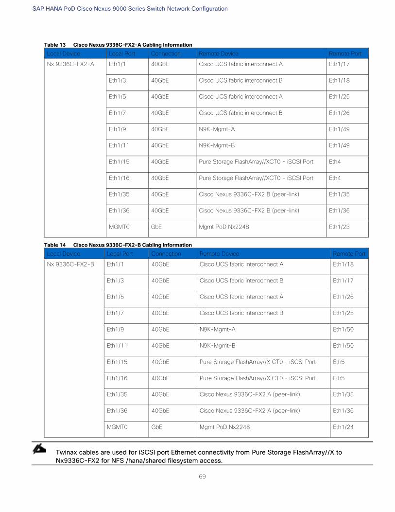
SAP HANA PoD Cisco Nexus 9000 Series Switch Network Configuration
69
Table 13 Cisco Nexus 9336C-FX2-A Cabling Information
Local Device Local Port Connection Remote Device Remote Port
Nx 9336C-FX2-A
Eth1/1 40GbE Cisco UCS fabric interconnect A Eth1/17
Eth1/3 40GbE Cisco UCS fabric interconnect B Eth1/18
Eth1/5 40GbE Cisco UCS fabric interconnect A Eth1/25
Eth1/7 40GbE Cisco UCS fabric interconnect B Eth1/26
Eth1/9 40GbE N9K-Mgmt-A Eth1/49
Eth1/11 40GbE N9K-Mgmt-B Eth1/49
Eth1/15 40GbE Pure Storage FlashArray//XCT0 - iSCSI Port Eth4
Eth1/16 40GbE Pure Storage FlashArray//XCT0 - iSCSI Port Eth4
Eth1/35 40GbE Cisco Nexus 9336C-FX2 B (peer-link) Eth1/35
Eth1/36 40GbE Cisco Nexus 9336C-FX2 B (peer-link) Eth1/36
MGMT0 GbE Mgmt PoD Nx2248 Eth1/23
Table 14 Cisco Nexus 9336C-FX2-B Cabling Information
Local Device Local Port Connection Remote Device Remote Port
Nx 9336C-FX2-B
Eth1/1 40GbE Cisco UCS fabric interconnect A Eth1/18
Eth1/3 40GbE Cisco UCS fabric interconnect B Eth1/17
Eth1/5 40GbE Cisco UCS fabric interconnect A Eth1/26
Eth1/7 40GbE Cisco UCS fabric interconnect B Eth1/25
Eth1/9 40GbE N9K-Mgmt-A Eth1/50
Eth1/11 40GbE N9K-Mgmt-B Eth1/50
Eth1/15 40GbE Pure Storage FlashArray//X CT0 - iSCSI Port Eth5
Eth1/16 40GbE Pure Storage FlashArray//X CT0 - iSCSI Port Eth5
Eth1/35 40GbE Cisco Nexus 9336C-FX2 A (peer-link) Eth1/35
Eth1/36 40GbE Cisco Nexus 9336C-FX2 A (peer-link) Eth1/36
MGMT0 GbE Mgmt PoD Nx2248 Eth1/24
Twinax cables are used for iSCSI port Ethernet connectivity from Pure Storage FlashArray//X to
Nx9336C-FX2 for NFS /hana/shared filesystem access.
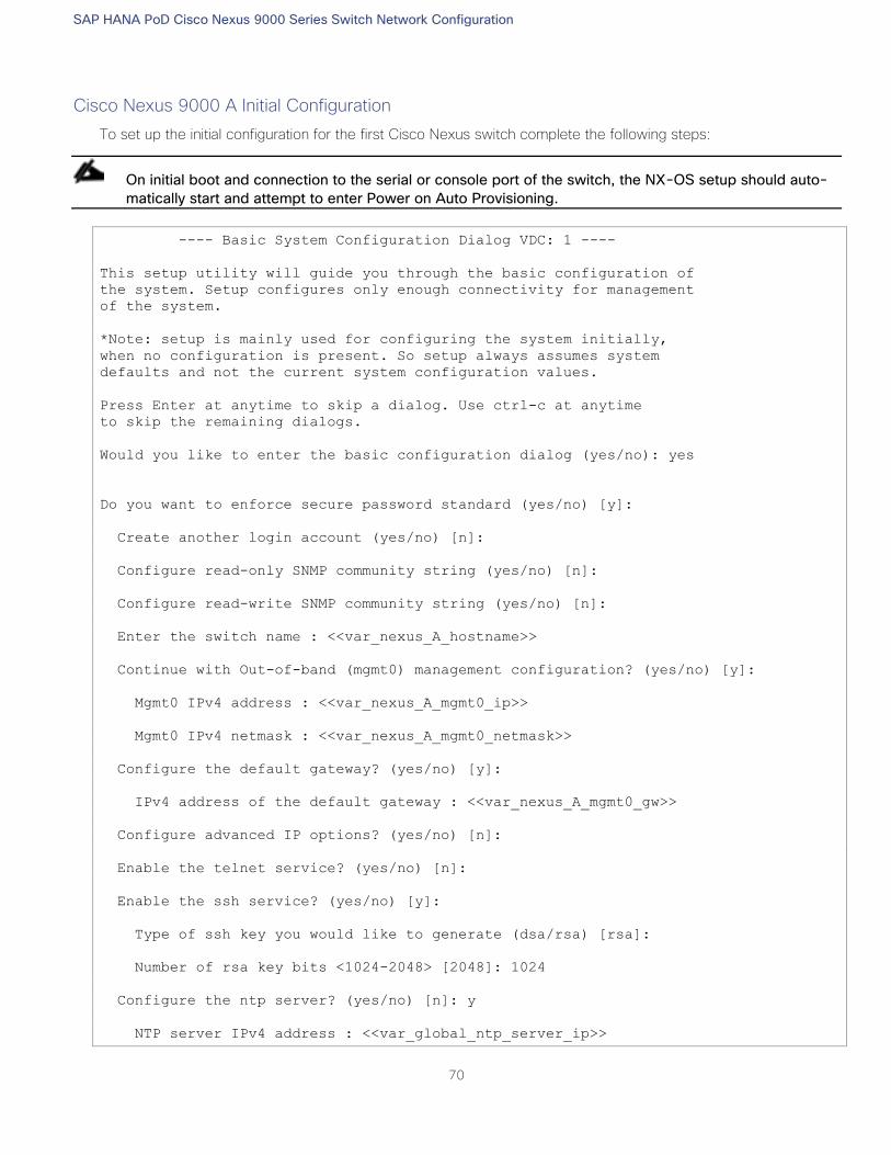
SAP HANA PoD Cisco Nexus 9000 Series Switch Network Configuration
70
Cisco Nexus 9000 A Initial Configuration
To set up the initial configuration for the first Cisco Nexus switch complete the following steps:
On initial boot and connection to the serial or console port of the switch, the NX-OS setup should auto-
matically start and attempt to enter Power on Auto Provisioning.
---- Basic System Configuration Dialog VDC: 1 ----
This setup utility will guide you through the basic configuration of
the system. Setup configures only enough connectivity for management
of the system.
*Note: setup is mainly used for configuring the system initially,
when no configuration is present. So setup always assumes system
defaults and not the current system configuration values.
Press Enter at anytime to skip a dialog. Use ctrl-c at anytime
to skip the remaining dialogs.
Would you like to enter the basic configuration dialog (yes/no): yes
Do you want to enforce secure password standard (yes/no) [y]:
Create another login account (yes/no) [n]:
Configure read-only SNMP community string (yes/no) [n]:
Configure read-write SNMP community string (yes/no) [n]:
Enter the switch name : <<var_nexus_A_hostname>>
Continue with Out-of-band (mgmt0) management configuration? (yes/no) [y]:
Mgmt0 IPv4 address : <<var_nexus_A_mgmt0_ip>>
Mgmt0 IPv4 netmask : <<var_nexus_A_mgmt0_netmask>>
Configure the default gateway? (yes/no) [y]:
IPv4 address of the default gateway : <<var_nexus_A_mgmt0_gw>>
Configure advanced IP options? (yes/no) [n]:
Enable the telnet service? (yes/no) [n]:
Enable the ssh service? (yes/no) [y]:
Type of ssh key you would like to generate (dsa/rsa) [rsa]:
Number of rsa key bits <1024-2048> [2048]: 1024
Configure the ntp server? (yes/no) [n]: y
NTP server IPv4 address : <<var_global_ntp_server_ip>>
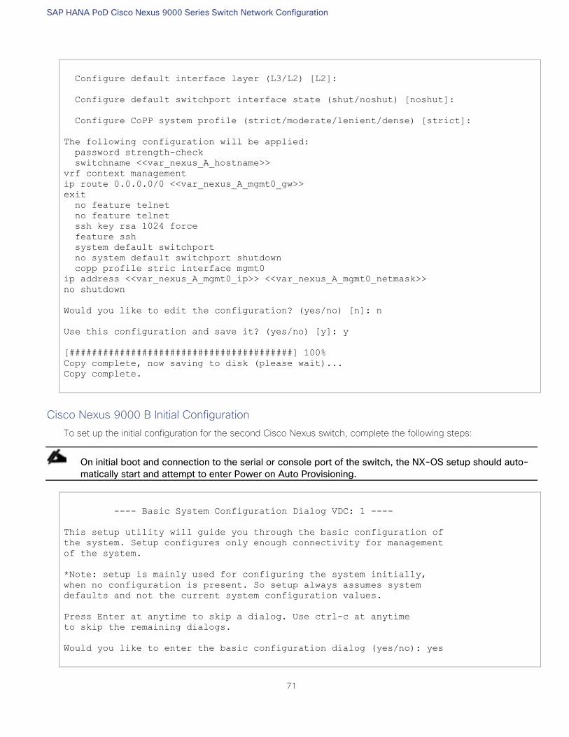
SAP HANA PoD Cisco Nexus 9000 Series Switch Network Configuration
71
Configure default interface layer (L3/L2) [L2]:
Configure default switchport interface state (shut/noshut) [noshut]:
Configure CoPP system profile (strict/moderate/lenient/dense) [strict]:
The following configuration will be applied:
password strength-check
switchname <<var_nexus_A_hostname>>
vrf context management
ip route 0.0.0.0/0 <<var_nexus_A_mgmt0_gw>>
exit
no feature telnet
no feature telnet
ssh key rsa 1024 force
feature ssh
system default switchport
no system default switchport shutdown
copp profile stric interface mgmt0
ip address <<var_nexus_A_mgmt0_ip>> <<var_nexus_A_mgmt0_netmask>>
no shutdown
Would you like to edit the configuration? (yes/no) [n]: n
Use this configuration and save it? (yes/no) [y]: y
[########################################] 100%
Copy complete, now saving to disk (please wait)...
Copy complete.
Cisco Nexus 9000 B Initial Configuration
To set up the initial configuration for the second Cisco Nexus switch, complete the following steps:
On initial boot and connection to the serial or console port of the switch, the NX-OS setup should auto-
matically start and attempt to enter Power on Auto Provisioning.
---- Basic System Configuration Dialog VDC: 1 ----
This setup utility will guide you through the basic configuration of
the system. Setup configures only enough connectivity for management
of the system.
*Note: setup is mainly used for configuring the system initially,
when no configuration is present. So setup always assumes system
defaults and not the current system configuration values.
Press Enter at anytime to skip a dialog. Use ctrl-c at anytime
to skip the remaining dialogs.
Would you like to enter the basic configuration dialog (yes/no): yes
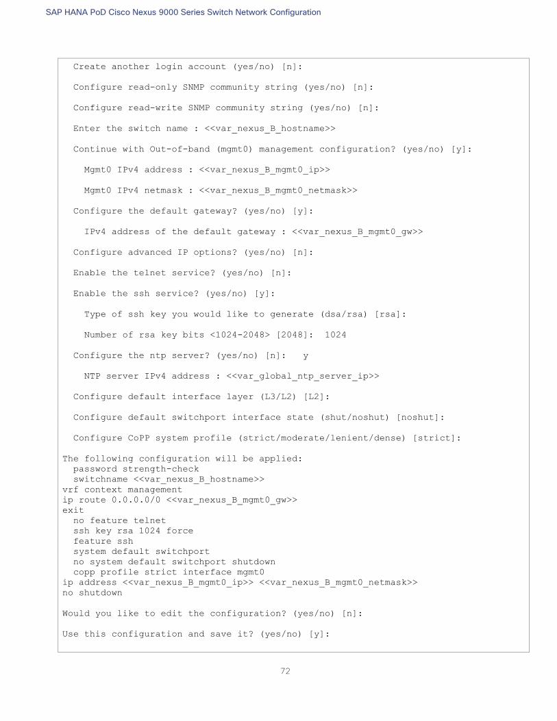
SAP HANA PoD Cisco Nexus 9000 Series Switch Network Configuration
72
Create another login account (yes/no) [n]:
Configure read-only SNMP community string (yes/no) [n]:
Configure read-write SNMP community string (yes/no) [n]:
Enter the switch name : <<var_nexus_B_hostname>>
Continue with Out-of-band (mgmt0) management configuration? (yes/no) [y]:
Mgmt0 IPv4 address : <<var_nexus_B_mgmt0_ip>>
Mgmt0 IPv4 netmask : <<var_nexus_B_mgmt0_netmask>>
Configure the default gateway? (yes/no) [y]:
IPv4 address of the default gateway : <<var_nexus_B_mgmt0_gw>>
Configure advanced IP options? (yes/no) [n]:
Enable the telnet service? (yes/no) [n]:
Enable the ssh service? (yes/no) [y]:
Type of ssh key you would like to generate (dsa/rsa) [rsa]:
Number of rsa key bits <1024-2048> [2048]: 1024
Configure the ntp server? (yes/no) [n]: y
NTP server IPv4 address : <<var_global_ntp_server_ip>>
Configure default interface layer (L3/L2) [L2]:
Configure default switchport interface state (shut/noshut) [noshut]:
Configure CoPP system profile (strict/moderate/lenient/dense) [strict]:
The following configuration will be applied:
password strength-check
switchname <<var_nexus_B_hostname>>
vrf context management
ip route 0.0.0.0/0 <<var_nexus_B_mgmt0_gw>>
exit
no feature telnet
ssh key rsa 1024 force
feature ssh
system default switchport
no system default switchport shutdown
copp profile strict interface mgmt0
ip address <<var_nexus_B_mgmt0_ip>> <<var_nexus_B_mgmt0_netmask>>
no shutdown
Would you like to edit the configuration? (yes/no) [n]:
Use this configuration and save it? (yes/no) [y]:
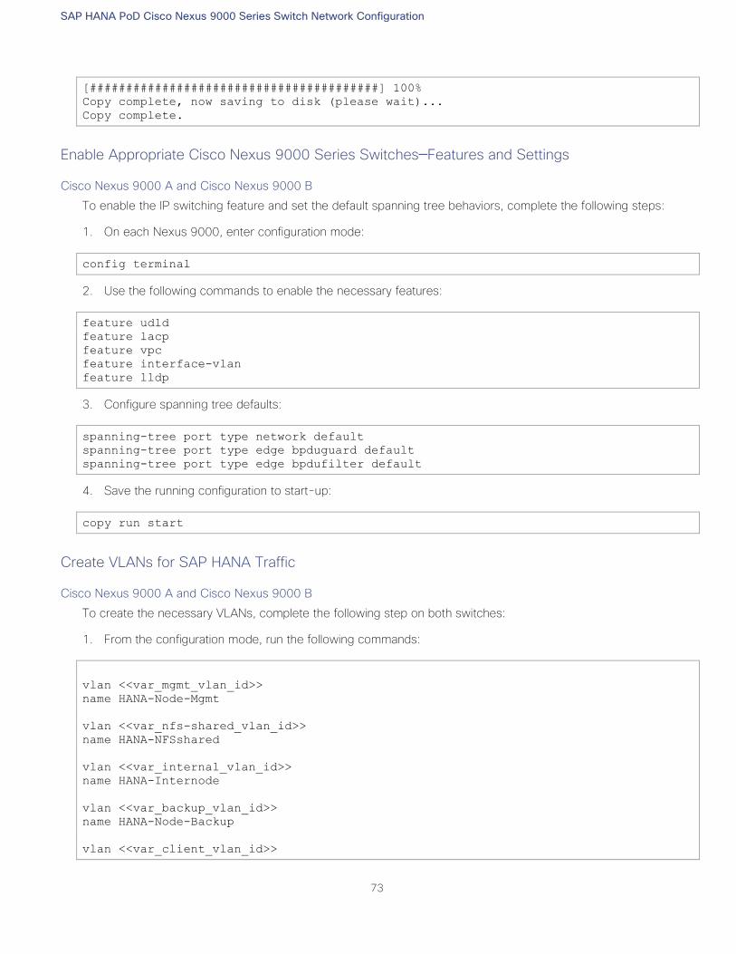
SAP HANA PoD Cisco Nexus 9000 Series Switch Network Configuration
73
[########################################] 100%
Copy complete, now saving to disk (please wait)...
Copy complete.
Enable Appropriate Cisco Nexus 9000 Series Switches─Features and Settings
Cisco Nexus 9000 A and Cisco Nexus 9000 B
To enable the IP switching feature and set the default spanning tree behaviors, complete the following steps:
1. On each Nexus 9000, enter configuration mode:
config terminal
2. Use the following commands to enable the necessary features:
feature udld
feature lacp
feature vpc
feature interface-vlan
feature lldp
3. Configure spanning tree defaults:
spanning-tree port type network default
spanning-tree port type edge bpduguard default
spanning-tree port type edge bpdufilter default
4. Save the running configuration to start-up:
copy run start
Create VLANs for SAP HANA Traffic
Cisco Nexus 9000 A and Cisco Nexus 9000 B
To create the necessary VLANs, complete the following step on both switches:
1. From the configuration mode, run the following commands:
vlan <<var_mgmt_vlan_id>>
name HANA-Node-Mgmt
vlan <<var_nfs-shared_vlan_id>>
name HANA-NFSshared
vlan <<var_internal_vlan_id>>
name HANA-Internode
vlan <<var_backup_vlan_id>>
name HANA-Node-Backup
vlan <<var_client_vlan_id>>
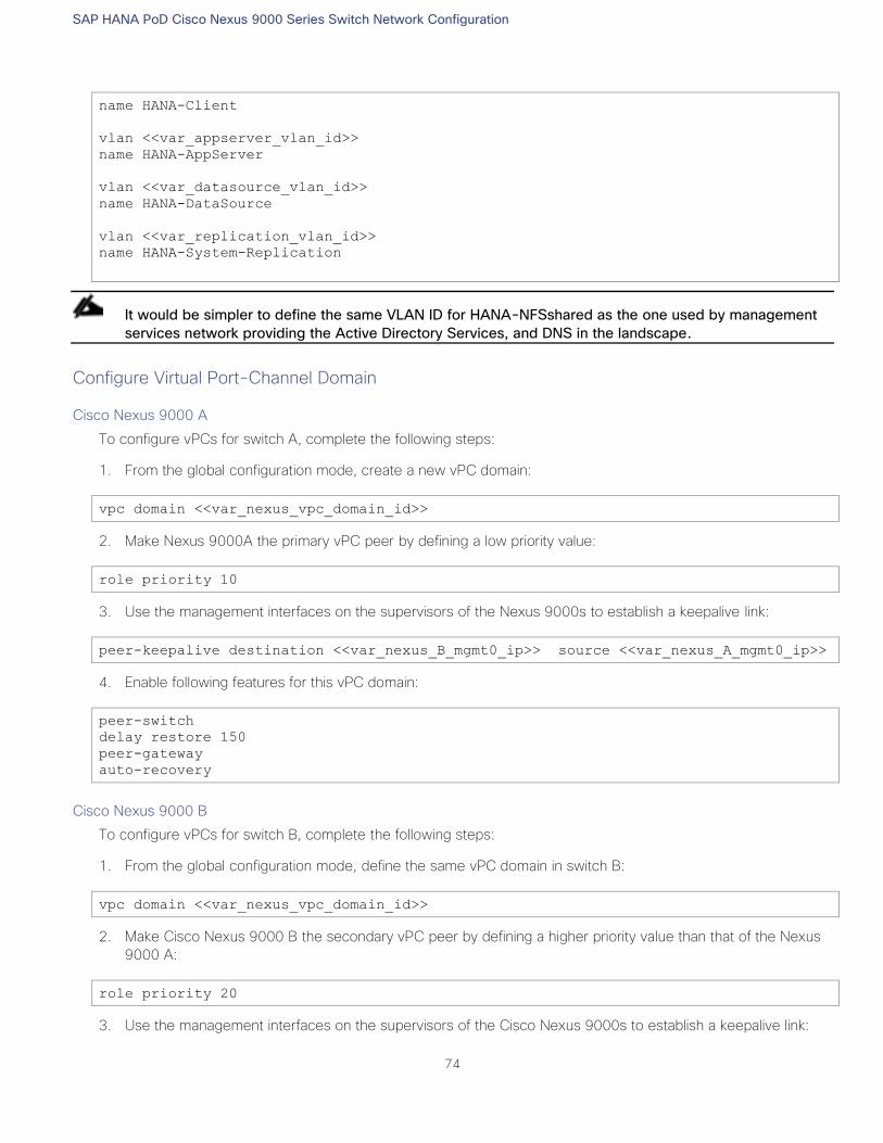
SAP HANA PoD Cisco Nexus 9000 Series Switch Network Configuration
74
name HANA-Client
vlan <<var_appserver_vlan_id>>
name HANA-AppServer
vlan <<var_datasource_vlan_id>>
name HANA-DataSource
vlan <<var_replication_vlan_id>>
name HANA-System-Replication
It would be simpler to define the same VLAN ID for HANA-NFSshared as the one used by management
services network providing the Active Directory Services, and DNS in the landscape.
Configure Virtual Port-Channel Domain
Cisco Nexus 9000 A
To configure vPCs for switch A, complete the following steps:
1. From the global configuration mode, create a new vPC domain:
vpc domain <<var_nexus_vpc_domain_id>>
2. Make Nexus 9000A the primary vPC peer by defining a low priority value:
role priority 10
3. Use the management interfaces on the supervisors of the Nexus 9000s to establish a keepalive link:
peer-keepalive destination <<var_nexus_B_mgmt0_ip>> source <<var_nexus_A_mgmt0_ip>>
4. Enable following features for this vPC domain:
peer-switch
delay restore 150
peer-gateway
auto-recovery
Cisco Nexus 9000 B
To configure vPCs for switch B, complete the following steps:
1. From the global configuration mode, define the same vPC domain in switch B:
vpc domain <<var_nexus_vpc_domain_id>>
2. Make Cisco Nexus 9000 B the secondary vPC peer by defining a higher priority value than that of the Nexus
9000 A:
role priority 20
3. Use the management interfaces on the supervisors of the Cisco Nexus 9000s to establish a keepalive link:
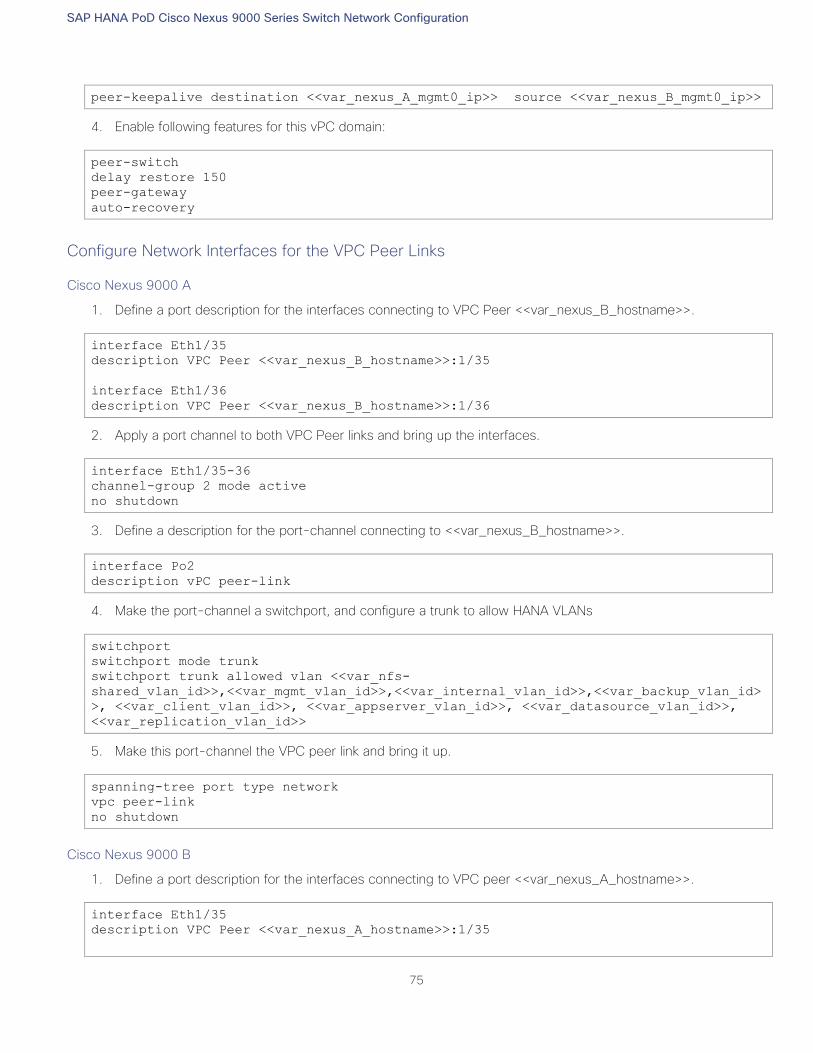
SAP HANA PoD Cisco Nexus 9000 Series Switch Network Configuration
75
peer-keepalive destination <<var_nexus_A_mgmt0_ip>> source <<var_nexus_B_mgmt0_ip>>
4. Enable following features for this vPC domain:
peer-switch
delay restore 150
peer-gateway
auto-recovery
Configure Network Interfaces for the VPC Peer Links
Cisco Nexus 9000 A
1. Define a port description for the interfaces connecting to VPC Peer <<var_nexus_B_hostname>>.
interface Eth1/35
description VPC Peer <<var_nexus_B_hostname>>:1/35
interface Eth1/36
description VPC Peer <<var_nexus_B_hostname>>:1/36
2. Apply a port channel to both VPC Peer links and bring up the interfaces.
interface Eth1/35-36
channel-group 2 mode active
no shutdown
3. Define a description for the port-channel connecting to <<var_nexus_B_hostname>>.
interface Po2
description vPC peer-link
4. Make the port-channel a switchport, and configure a trunk to allow HANA VLANs
switchport
switchport mode trunk
switchport trunk allowed vlan <<var_nfs-
shared_vlan_id>>,<<var_mgmt_vlan_id>>,<<var_internal_vlan_id>>,<<var_backup_vlan_id>
>, <<var_client_vlan_id>>, <<var_appserver_vlan_id>>, <<var_datasource_vlan_id>>,
<<var_replication_vlan_id>>
5. Make this port-channel the VPC peer link and bring it up.
spanning-tree port type network
vpc peer-link
no shutdown
Cisco Nexus 9000 B
1. Define a port description for the interfaces connecting to VPC peer <<var_nexus_A_hostname>>.
interface Eth1/35
description VPC Peer <<var_nexus_A_hostname>>:1/35
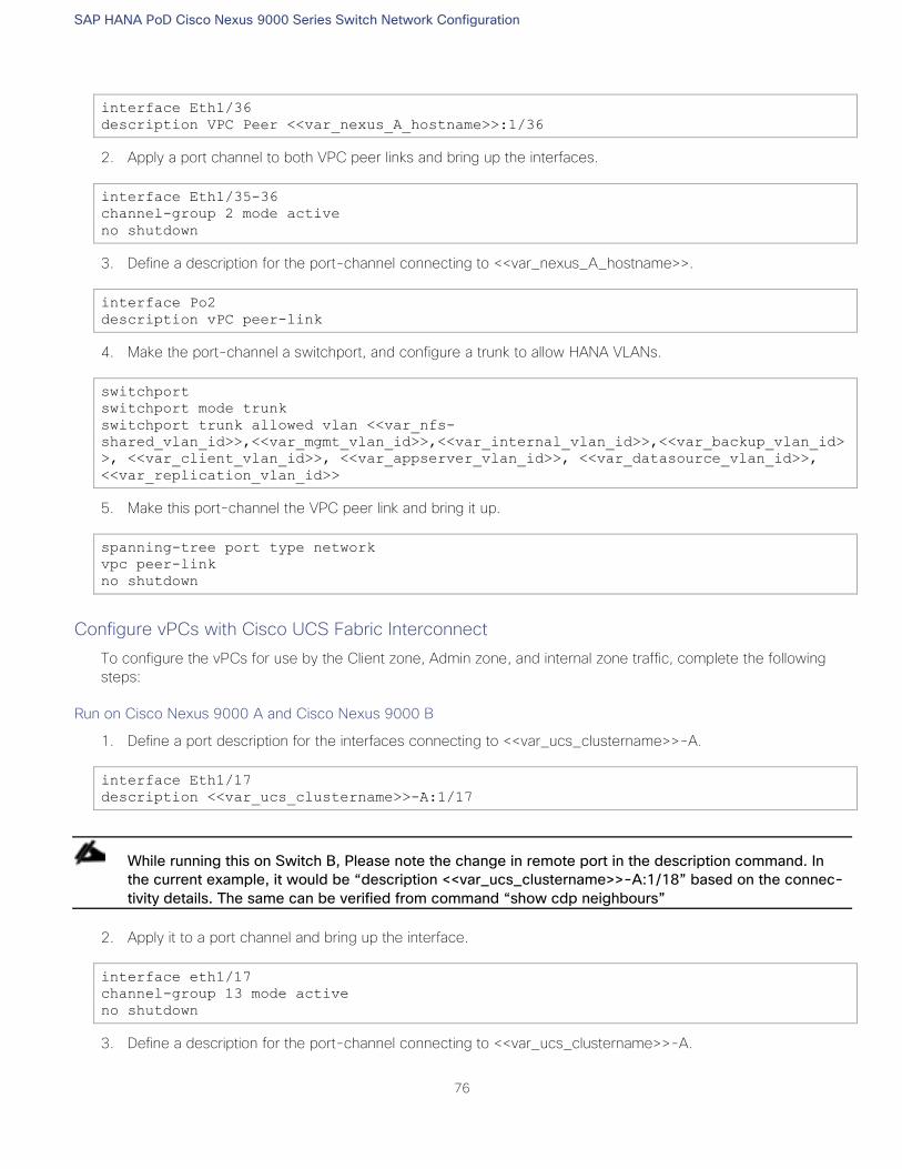
SAP HANA PoD Cisco Nexus 9000 Series Switch Network Configuration
76
interface Eth1/36
description VPC Peer <<var_nexus_A_hostname>>:1/36
2. Apply a port channel to both VPC peer links and bring up the interfaces.
interface Eth1/35-36
channel-group 2 mode active
no shutdown
3. Define a description for the port-channel connecting to <<var_nexus_A_hostname>>.
interface Po2
description vPC peer-link
4. Make the port-channel a switchport, and configure a trunk to allow HANA VLANs.
switchport
switchport mode trunk
switchport trunk allowed vlan <<var_nfs-
shared_vlan_id>>,<<var_mgmt_vlan_id>>,<<var_internal_vlan_id>>,<<var_backup_vlan_id>
>, <<var_client_vlan_id>>, <<var_appserver_vlan_id>>, <<var_datasource_vlan_id>>,
<<var_replication_vlan_id>>
5. Make this port-channel the VPC peer link and bring it up.
spanning-tree port type network
vpc peer-link
no shutdown
Configure vPCs with Cisco UCS Fabric Interconnect
To configure the vPCs for use by the Client zone, Admin zone, and internal zone traffic, complete the following
steps:
Run on Cisco Nexus 9000 A and Cisco Nexus 9000 B
1. Define a port description for the interfaces connecting to <<var_ucs_clustername>>-A.
interface Eth1/17
description <<var_ucs_clustername>>-A:1/17
While running this on Switch B, Please note the change in remote port in the description command. In
the current example, it would be “description <<var_ucs_clustername>>-A:1/18” based on the connec-
tivity details. The same can be verified from command “show cdp neighbours”
2. Apply it to a port channel and bring up the interface.
interface eth1/17
channel-group 13 mode active
no shutdown
3. Define a description for the port-channel connecting to <<var_ucs_clustername>>-A.
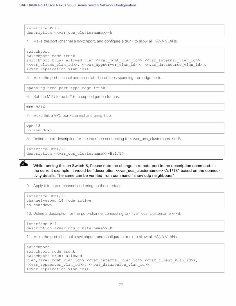
SAP HANA PoD Cisco Nexus 9000 Series Switch Network Configuration
77
interface Po13
description <<var_ucs_clustername>>-A
4. Make the port-channel a switchport, and configure a trunk to allow all HANA VLANs.
switchport
switchport mode trunk
switchport trunk allowed vlan <<var_mgmt_vlan_id>>,<<var_internal_vlan_id>>,
<<var_client_vlan_id>>, <<var_appserver_vlan_id>>, <<var_datasource_vlan_id>>,
<<var_replication_vlan_id>>
5. Make the port channel and associated interfaces spanning tree edge ports.
spanning-tree port type edge trunk
6. Set the MTU to be 9216 to support jumbo frames.
mtu 9216
7. Make this a VPC port-channel and bring it up.
vpc 13
no shutdown
8. Define a port description for the interface connecting to <<var_ucs_clustername>>-B.
interface Eth1/18
description <<var_ucs_clustername>>-B:1/17
While running this on Switch B, Please note the change in remote port in the description command. In
the current example, it would be “description <<var_ucs_clustername>>-A:1/18” based on the connec-
tivity details. The same can be verified from command “show cdp neighbours”
9. Apply it to a port channel and bring up the interface.
interface Eth1/18
channel-group 14 mode active
no shutdown
10. Define a description for the port-channel connecting to <<var_ucs_clustername>>-B.
interface P14
description <<var_ucs_clustername>>-B
11. Make the port-channel a switchport, and configure a trunk to allow all HANA VLANs.
switchport
switchport mode trunk
switchport trunk allowed
vlan,<<var_mgmt_vlan_id>>,<<var_internal_vlan_id>>,<<var_client_vlan_id>>,
<<var_appserver_vlan_id>>, <<var_datasource_vlan_id>>,
<<var_replication_vlan_id>>
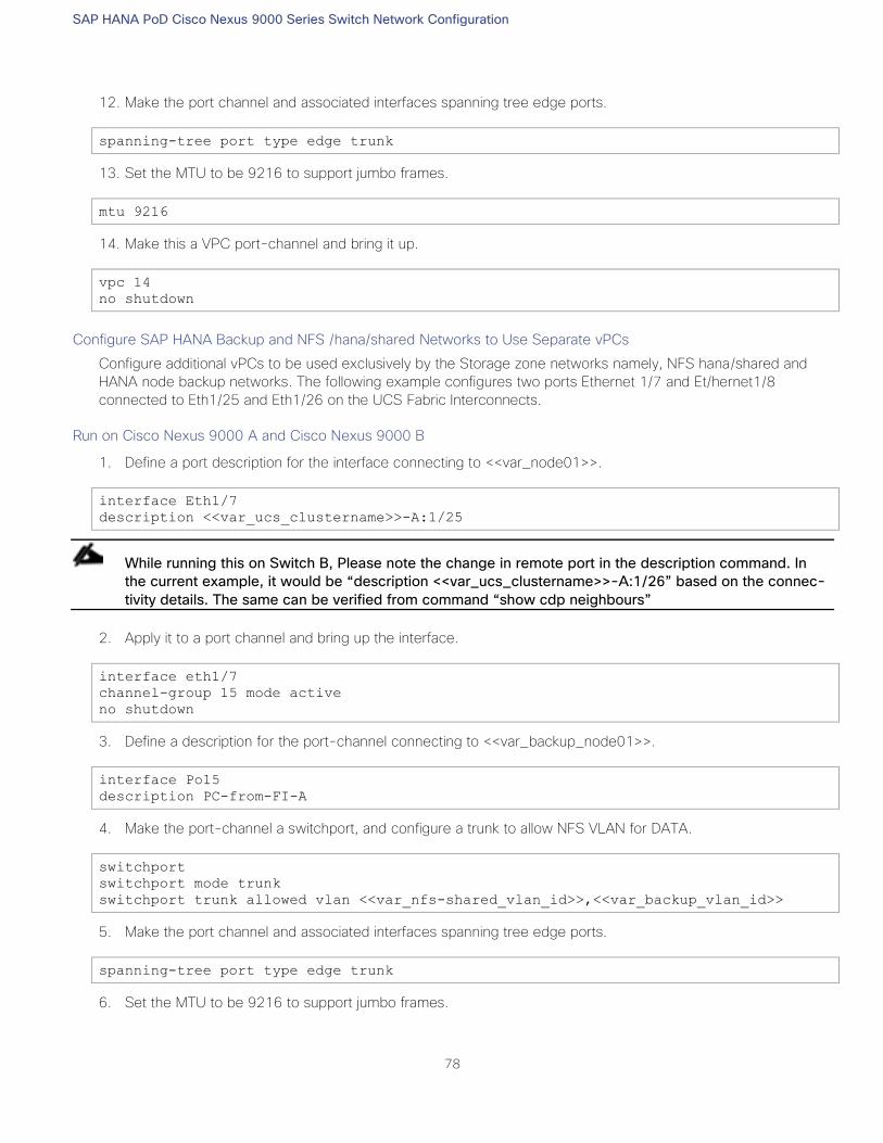
SAP HANA PoD Cisco Nexus 9000 Series Switch Network Configuration
78
12. Make the port channel and associated interfaces spanning tree edge ports.
spanning-tree port type edge trunk
13. Set the MTU to be 9216 to support jumbo frames.
mtu 9216
14. Make this a VPC port-channel and bring it up.
vpc 14
no shutdown
Configure SAP HANA Backup and NFS /hana/shared Networks to Use Separate vPCs
Configure additional vPCs to be used exclusively by the Storage zone networks namely, NFS hana/shared and
HANA node backup networks. The following example configures two ports Ethernet 1/7 and Et/hernet1/8
connected to Eth1/25 and Eth1/26 on the UCS Fabric Interconnects.
Run on Cisco Nexus 9000 A and Cisco Nexus 9000 B
1. Define a port description for the interface connecting to <<var_node01>>.
interface Eth1/7
description <<var_ucs_clustername>>-A:1/25
While running this on Switch B, Please note the change in remote port in the description command. In
the current example, it would be “description <<var_ucs_clustername>>-A:1/26” based on the connec-
tivity details. The same can be verified from command “show cdp neighbours”
2. Apply it to a port channel and bring up the interface.
interface eth1/7
channel-group 15 mode active
no shutdown
3. Define a description for the port-channel connecting to <<var_backup_node01>>.
interface Po15
description PC-from-FI-A
4. Make the port-channel a switchport, and configure a trunk to allow NFS VLAN for DATA.
switchport
switchport mode trunk
switchport trunk allowed vlan <<var_nfs-shared_vlan_id>>,<<var_backup_vlan_id>>
5. Make the port channel and associated interfaces spanning tree edge ports.
spanning-tree port type edge trunk
6. Set the MTU to be 9216 to support jumbo frames.
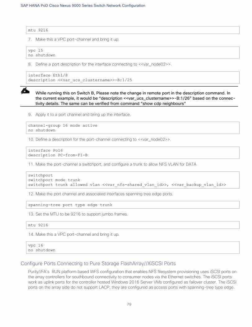
SAP HANA PoD Cisco Nexus 9000 Series Switch Network Configuration
79
mtu 9216
7. Make this a VPC port-channel and bring it up.
vpc 15
no shutdown
8. Define a port description for the interface connecting to <<var_node02>>.
interface Eth1/8
description <<var_ucs_clustername>>-B:1/25
While running this on Switch B, Please note the change in remote port in the description command. In
the current example, it would be “description <<var_ucs_clustername>>-B:1/26” based on the connec-
tivity details. The same can be verified from command “show cdp neighbours”
9. Apply it to a port channel and bring up the interface.
channel-group 16 mode active
no shutdown
10. Define a description for the port-channel connecting to <<var_node02>>.
interface Po16
description PC-from-FI-B
11. Make the port-channel a switchport, and configure a trunk to allow NFS VLAN for DATA
switchport
switchport mode trunk
switchport trunk allowed vlan <<var_nfs-shared_vlan_id>>, <<var_backup_vlan_id>>
12. Make the port channel and associated interfaces spanning tree edge ports.
spanning-tree port type edge trunk
13. Set the MTU to be 9216 to support jumbo frames.
mtu 9216
14. Make this a VPC port-channel and bring it up.
vpc 16
no shutdown
Configure Ports Connecting to Pure Storage FlashArray//XiSCSI Ports
Purity//FA’s RUN platform based WFS configuration that enables NFS filesystem provisioning uses iSCSI ports on
the array controllers for southbound connectivity to consumer nodes via the Ethernet switches. The iSCSI ports
work as uplink ports for the controller hosted Windows 2016 Server VMs configured as failover cluster. The iSCSI
ports on the array side do not support LACP; they are configured as access ports with spanning-tree type edge.
SAP HANA PoD Cisco Nexus 9000 Series Switch Network Configuration
80
In this section, you will configure the ports that connect to Pure Storage FlashArray//X’s iSCSI ports that provide
IP connectivity to NFS share for HANA nodes.
Cisco Nexus 9000 A
1. Define a port description for the interface connecting to iSCSI port eth4 on array controller 0.
interface Eth1/15
description Pure-CT0-iscsi-eth4
2. Configure it as access port and assign the NFS network VLAN.
switchport access <<var-nfs-shared-vlan-id>>
spanning-tree port type edge
no shutdown
3. Define a port description for the interface connecting to iSCSI port eth4 on array controller 1
interface eth1/16
description Pure-CT1-iscsi-eth4
4. Configure it as access port and assign the NFS network VLAN.
switchport access <<var-nfs-shared-vlan-id>>
spanning-tree port type edge
no shutdown
Cisco Nexus 9000 B
1. Define a port description for the interface connecting to iSCSI port eth5 on array controller 0.
interface Eth1/15
description Pure-CT0-iscsi-eth5
2. Configure it as access port and assign the NFS network VLAN.
switchport access <<var-nfs-shared-vlan-id>>
spanning-tree port type edge
no shutdown
3. Define a port description for the interface connecting to iSCSI port eth5 on array controller 1.
interface eth1/16
description Pure-CT1-iscsi-eth5
4. Configure it as access port and assign the NFS network VLAN.
switchport access <<var-nfs-shared-vlan-id>>
spanning-tree port type edge
no shutdown
Make sure to save the configuration to the startup config using the command “copy r s”
SAP HANA PoD Cisco Nexus 9000 Series Switch Network Configuration
81
Configure Cisco MDS 9148S Switches
Figure 20 illustrates the connected MDS Switches to Fabric Interconnects and Pure Storage FlashArray//X.
Figure 20 MDS, FI and Pure Storage Layout
For this solution, we connected four ports (ports 1-4) of MDS Switch A to Fabric Interconnect A (ports 1-4).
Similarly, we connected four ports (ports 1-4) of MDS Switch B to Fabric Interconnect B (ports 1-4). We
connected four ports (ports 33-36) of MDS Switch A to Pure Storage FlashArray//X. Similarly, we connected four
ports (ports 33-36) of MDS Switch B to Pure Storage FlashArray//X as shown in Table 15 . All ports carry 16 GB
FC Traffic.
Table 15 MDS 9148S –A Port Connection to Cisco UCS FI-A and Pure Storage
Local Device Local Port Connection Remote Device Remote Port
Cisco MDS - A
fc 1/1 16Gb UCS FI- A 1/1
fc 1/2 16Gb UCS FI- A 1/2
fc 1/3 16Gb UCS FI- A 1/3
fc 1/4 16Gb UCS FI- A 1/4
fc 1/33 16Gb Pure Storage FlashArray//X - Storage Contoller-
0
CT0-FC2
fc 1/34 16Gb Pure Storage FlashArray//X - Storage Contoller-
1
CT1-FC2
fc 1/35 16Gb Pure Storage FlashArray//X - Storage Contoller-
0
CT0-FC0
fc 1/36 16Gb Pure Storage FlashArray//X - Storage Contoller-
1
CT1-FC0
MGMT0 GbE Customer’s Management Switch Any
SAP HANA PoD Cisco Nexus 9000 Series Switch Network Configuration
82
Table 16 MDS 9148S –B Port Connection to Cisco UCS FI-B and Pure Storage
Local Device Local Port Connection Remote Device Remote Port
Cisco MDS - B
fc 1/1 16Gb UCS FI- B 1/1
fc 1/2 16Gb UCS FI- B 1/2
fc 1/3 16Gb UCS FI- B 1/3
fc 1/4 16Gb UCS FI- B 1/4
fc 1/33 16Gb Pure Storage FlashArray//X - Storage Contoller-
0
CT0-FC3
fc 1/34 16Gb Pure Storage FlashArray//X - Storage Contoller-
1
CT1-FC3
fc 1/35 16Gb Pure Storage FlashArray//X - Storage Contoller-
0
CT0-FC1
fc 1/36 16Gb Pure Storage FlashArray//X - Storage Contoller-
1
CT1-FC1
MGMT0 GbE Customer’s Management Switch Any
This section explains the fabric switch configuration required for the FlashStack for SAP HANA.
This example uses the Fibre Channel Port Channel between the Cisco MDS switches and the Cisco UCS Fabric
Interconnects.
Since Cisco UCS is not configured at this time, the FC ports connected to the Cisco UCS Fabric Inter-
connects will not come up.
Cisco MDS Initial Configuration
Cisco MDS 9148S A
Connect to the console port of MDS9148S-A.
---- System Admin Account Setup ----
Do you want to enforce secure password standard (yes/no) [y]: yes
Enter the password for "admin": <<var_mgmt_passwd>>
Confirm the password for "admin": <<var_mgmt_passwd>>
---- Basic System Configuration Dialog ----
This setup utility will guide you through the basic configuration of
the system. Setup configures only enough connectivity for management
of the system.
Please register Cisco MDS 9000 Family devices promptly with your
SAP HANA PoD Cisco Nexus 9000 Series Switch Network Configuration
83
supplier. Failure to register may affect response times for initial
service calls. MDS devices must be registered to receive entitled
support services.
Press Enter at any time to skip a dialog. Use ctrl-c at anytime
to skip the remaining dialogs.
Would you like to enter the basic configuration dialog (yes/no): yes
Create another login account (yes/no) [n]:
Configure read-only SNMP community string (yes/no) [n]: yes
SNMP community string :
Enter the switch name : <<var_mds-a_name>>
Continue with Out-of-band (mgmt0) management configuration? (yes/no) [y]:
Mgmt0 IPv4 address : <<var_mds-a_ip>>
Mgmt0 IPv4 netmask : <<var_mgmt_netmask>>
Configure the default gateway? (yes/no) [y]:
IPv4 address of the default gateway : <<var_mgmt_gw>>
Configure advanced IP options? (yes/no) [n]:
Enable the ssh service? (yes/no) [y]:
Type of ssh key you would like to generate (dsa/rsa) [rsa]:
Number of rsa key bits <768-2048> [1024]: 2048
Enable the telnet service? (yes/no) [n]:
Enable the http-server? (yes/no) [y]:
Configure clock? (yes/no) [n]:
Configure timezone? (yes/no) [n]: n
Configure the ntp server? (yes/no) [n]: y
NTP server IPv4 address : <<var_global_ntp_server_ip>>
Configure default switchport interface state (shut/noshut) [shut]: noshut
Configure default switchport trunk mode (on/off/auto) [on]: auto
Configure default switchport port mode F (yes/no) [n]: y
Configure default zone policy (permit/deny) [deny]:
Enable full zoneset distribution? (yes/no) [n]:
SAP HANA PoD Cisco Nexus 9000 Series Switch Network Configuration
84
Configure default zone mode (basic/enhanced) [basic]:
The following configuration will be applied:
password strength-check
snmp-server community <<var_snmp_ro_string>> ro
switchname <<var_mds-a_name>>
interface mgmt0
ip address <<var_mds-a_ip>> <<var_mgmt_netmask>>
no shutdown
ip default-gateway <<var_mgmt_gw>>
ssh key rsa 2048 force
feature ssh
no feature telnet
feature http-server
ntp server <<var_global_ntp_server_ip>>
no system default switchport shutdown
system default switchport trunk mode auto
system default switchport mode F
no system default zone default-zone permit
no system default zone distribute full
no system default zone mode enhanced
Would you like to edit the configuration? (yes/no) [n]: no
Use this configuration and save it? (yes/no) [y]: yes
[########################################] 100%
Cisco MDS 9148S B
Connect to the console port of MDS9148S-B.
---- System Admin Account Setup ----
Do you want to enforce secure password standard (yes/no) [y]: yes
Enter the password for "admin": <<var_mgmt_passwd>>
Confirm the password for "admin": <<var_mgmt_passwd>>
---- Basic System Configuration Dialog ----
This setup utility will guide you through the basic configuration of
the system. Setup configures only enough connectivity for management
of the system.
Please register Cisco MDS 9000 Family devices promptly with your
supplier. Failure to register may affect response times for initial
service calls. MDS devices must be registered to receive entitled
support services.
Press Enter at any time to skip a dialog. Use ctrl-c at anytime
to skip the remaining dialogs.
Would you like to enter the basic configuration dialog (yes/no): yes
Create another login account (yes/no) [n]:
SAP HANA PoD Cisco Nexus 9000 Series Switch Network Configuration
85
Configure read-only SNMP community string (yes/no) [n]: yes
SNMP community string :
Enter the switch name : <<var_mds-b_name>>
Continue with Out-of-band (mgmt0) management configuration? (yes/no) [y]:
Mgmt0 IPv4 address : <<var_mds-b_ip>>
Mgmt0 IPv4 netmask : <<var_mgmt_netmask>>
Configure the default gateway? (yes/no) [y]:
IPv4 address of the default gateway : <<var_mgmt_gw>>
Configure advanced IP options? (yes/no) [n]:
Enable the ssh service? (yes/no) [y]:
Type of ssh key you would like to generate (dsa/rsa) [rsa]:
Number of rsa key bits <768-2048> [1024]: 2048
Enable the telnet service? (yes/no) [n]:
Enable the http-server? (yes/no) [y]:
Configure clock? (yes/no) [n]:
Configure timezone? (yes/no) [n]: n
Configure the ntp server? (yes/no) [n]: y
NTP server IPv4 address : <<var_global_ntp_server_ip>>
Configure default switchport interface state (shut/noshut) [shut]: noshut
Configure default switchport trunk mode (on/off/auto) [on]: auto
Configure default switchport port mode F (yes/no) [n]: y
Configure default zone policy (permit/deny) [deny]:
Enable full zoneset distribution? (yes/no) [n]:
Configure default zone mode (basic/enhanced) [basic]:
The following configuration will be applied:
password strength-check
snmp-server community <<var_snmp_ro_string>> ro
switchname <<var_mds-b_name>>
interface mgmt0
ip address <<var_mds-b_ip>> <<var_mgmt_netmask>>
no shutdown
ip default-gateway <<var_mgmt_gw>>
ssh key rsa 2048 force
SAP HANA PoD Cisco Nexus 9000 Series Switch Network Configuration
86
feature ssh
no feature telnet
feature http-server
ntp server <<var_global_ntp_server_ip>>
no system default switchport shutdown
system default switchport trunk mode auto
system default switchport mode F
no system default zone default-zone permit
no system default zone distribute full
no system default zone mode enhanced
Would you like to edit the configuration? (yes/no) [n]: no
Use this configuration and save it? (yes/no) [y]: yes
[########################################] 100%
Configure the Management Port and Enable Essential Features
On MDS 9148S A and B enter configuration mode and execute following commands:
interface mgmt 0
switchport speed 1000
no shut
Configure Fibre Channel Ports and Port Channels
1. On MDS 9148S A enter the configuration mode and enable the required features as shown below:
feature fport-channel-trunk
feature npiv
2. Use the following commands to configure the FC Port channel and add all FC ports connected to Cisco UCS
Fabric Interconnect A:
int port-channel <<var_fc-pc_a_id>>
channel mode active
int fc1/1-4
channel-group <<var_fc-pc_a_id>> force
int port-channel <<var_fc-pc_a_id>>
switchport mode F
switchport trunk mode off
no shut
3. On MDS 9148S B enter the configuration mode and enable the required features as shown below:
feature fport-channel-trunk
feature npiv
4. Use the following commands to configure the FC Port channel and add all FC ports connected to Cisco UCS
Fabric Interconnect B:
SAP HANA PoD Cisco Nexus 9000 Series Switch Network Configuration
87
int port channel <<var_fc-pc_b_id>>
channel mode active
int fc1/1-4
channel-group <<var_fc-pc_b_id>> force
int port channel <<var_fc-pc_b_id>>
switchport mode F
switchport trunk mode off
no shut
Configure VSANs
1. On MDS 9148S A enter the configuration mode and execute the following commands to configure the VSAN:
vsan database
vsan <<var_san_a_id>>
vsan <<var_san_a_id>> interface port channel <<var_fc-pc_a_id>>
vsan <<var_san_a_id>> interface fc 1/33
vsan <<var_san_a_id>> interface fc 1/34
vsan <<var_san_a_id>> interface fc 1/35
vsan <<var_san_a_id>> interface fc 1/36
int fc 1/33-36
switchport trunk mode off
switchport trunk allowed vsan <<var_san_a_id>>
port-license acquire
no shut
2. On MDS 9148S B enter the configuration mode and execute the following commands to configure the VSAN:
vsan database
vsan <<var_san_b_id>>
vsan <<var_san_b_id>> interface port channel <<var_fc-pc_b_id>>
vsan <<var_san_b_id>> interface fc 1/33
vsan <<var_san_b_id>> interface fc 1/34
vsan <<var_san_b_id>> interface fc 1/35
vsan <<var_san_b_id>> interface fc 1/36
int fc 1/33-36
switchport trunk mode off
switchport trunk allowed vsan <<var_san_b_id>>
port-license acquire
no shut
Make sure to save the configuration to the startup config using the command “copy r s”
SAP HANA PoD Cisco Nexus 9000 Series Switch Network Configuration
88
Cisco UCS Configuration Overview
It is beyond the scope of this document to cover detailed information about the Cisco UCS infrastructure setup
and connectivity. The documentation guides and examples are available at:
http://www.cisco.com/en/US/products/ps10281/products_installation_and_configuration_guides_list.html.
This document details only the tasks to configure Cisco UCS and presents minimal screenshots.
High-Level Steps to Configure Cisco Unified Computing System
The following are the high-level steps involved for a Cisco UCS configuration:
1. Configure Fabric Interconnects for a Cluster Setup.
2. Configure Fabric Interconnects for Chassis and Blade Discovery:
a. Configure Global Policies
b. Configure Server Ports
3. Configure LAN and SAN on Cisco UCS Manager:
a. Configure Ethernet LAN Uplink Ports
b. Configure FC SAN Uplink Ports
c. Configure VLAN
d. Configure VSAN
4. Configure UUID, IP, MAC, WWNN and WWPN Pools:
a. UUID Pool Creation
b. IP and MAC Pool Creation
c. WWNN and WWPN Pool Creation
5. Configure vNIC and vHBA Template:
a. Create vNIC Template one each for Fabric A and B
b. Create Storage vHBA Template one each for Fabric A and B
6. Configure Ethernet Uplink Port-Channels.
7. Create Server Boot Policy for SAN Boot.
Initial Setup of Cisco UCS 6332-16UP Fabric Interconnects
This section provides detailed procedures for configuring the Cisco Unified Computing System for use in SAP
HANA Scale-Out Solution environment. The steps are necessary to provision the Cisco UCS C-Series servers to
meet SAP HANA requirement.
Cisco UCS 6332-16UP Fabric Interconnect A
To configure the Cisco UCS Fabric Interconnect A, complete the following steps:
1. Connect to the console port on the first Cisco UCS 6300 Fabric Interconnect.
SAP HANA PoD Cisco Nexus 9000 Series Switch Network Configuration
89
Enter the configuration method: console
Enter the setup mode; setup newly or restore from backup.(setup/restore)? setup
You have chosen to setup a a new fabric interconnect? Continue? (y/n): y
Enforce strong passwords? (y/n) [y]: y
Enter the password for "admin": <<var_password>>
Enter the same password for "admin": <<var_password>>
Is this fabric interconnect part of a cluster (select 'no' for standalone)?
(yes/no) [n]: y
Which switch fabric (A|B): A
Enter the system name: <<var_ucs_clustername>>
Physical switch Mgmt0 IPv4 address: <<var_ucsa_mgmt_ip>>
Physical switch Mgmt0 IPv4 netmask: <<var_ucsa_mgmt_mask>>
IPv4 address of the default gateway: <<var_ucsa_mgmt_gateway>>
Cluster IPv4 address: <<var_ucs_cluster_ip>>
Configure DNS Server IPv4 address? (yes/no) [no]: y
DNS IPv4 address: <<var_nameserver_ip>>
Configure the default domain name? y
Default domain name: <<var_dns_domain_name>>
Join centralized management environment (UCS Central)? (yes/no) [n]: Enter
2. Review the settings printed to the console. If they are correct, answer yes to apply and save the configura-
tion.
3. Wait for the login prompt to make sure that the configuration has been saved.
Cisco UCS 6332-16UP Fabric Interconnect B
To configure the Cisco UCS Fabric Interconnect B, complete the following steps:
1. Connect to the console port on the second Cisco UCS 6332 Fabric Interconnect.
Enter the configuration method: console
Installer has detected the presence of a peer Fabric interconnect. This Fabric
interconnect will be added to the cluster. Do you want to continue {y|n}? y
Enter the admin password for the peer fabric interconnect: <<var_password>>
Physical switch Mgmt0 IPv4 address: <<var_ucsb_mgmt_ip>>
Apply and save the configuration (select ‘no’ if you want to re-enter)?
(yes/no): y
2. Wait for the login prompt to make sure that the configuration has been saved.
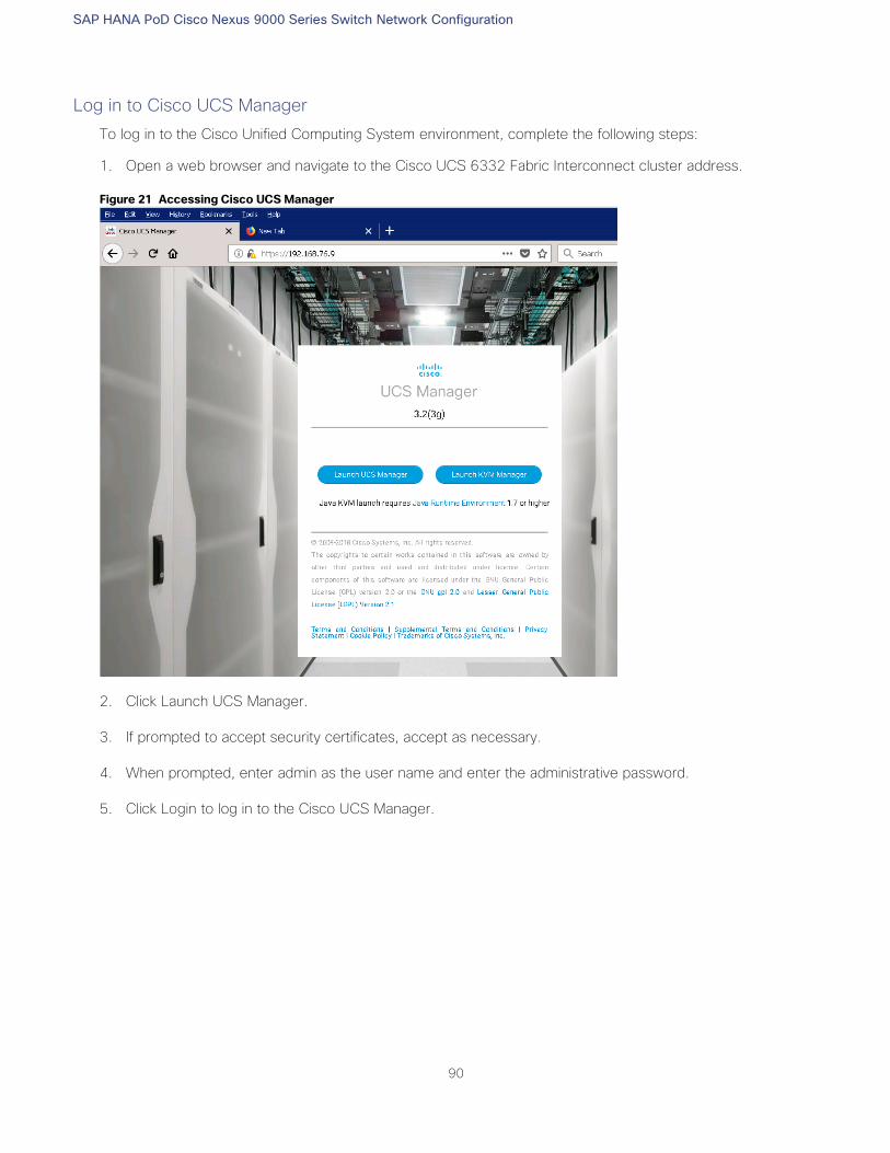
SAP HANA PoD Cisco Nexus 9000 Series Switch Network Configuration
90
Log in to Cisco UCS Manager
To log in to the Cisco Unified Computing System environment, complete the following steps:
1. Open a web browser and navigate to the Cisco UCS 6332 Fabric Interconnect cluster address.
Figure 21 Accessing Cisco UCS Manager
2. Click Launch UCS Manager.
3. If prompted to accept security certificates, accept as necessary.
4. When prompted, enter admin as the user name and enter the administrative password.
5. Click Login to log in to the Cisco UCS Manager.
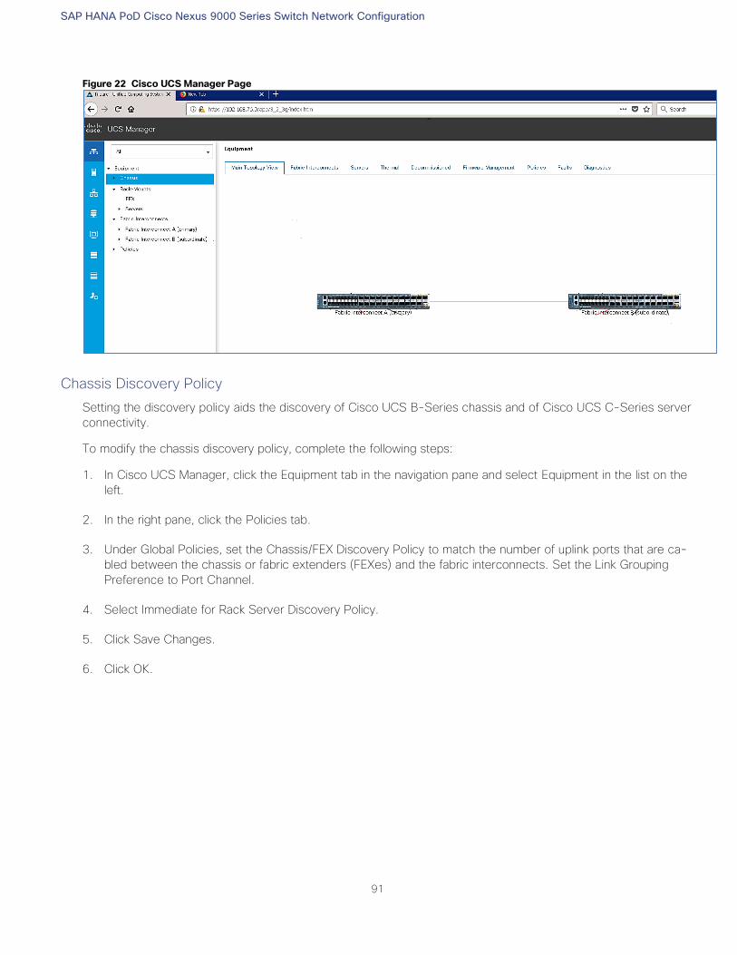
SAP HANA PoD Cisco Nexus 9000 Series Switch Network Configuration
91
Figure 22 Cisco UCS Manager Page
Chassis Discovery Policy
Setting the discovery policy aids the discovery of Cisco UCS B-Series chassis and of Cisco UCS C-Series server
connectivity.
To modify the chassis discovery policy, complete the following steps:
1. In Cisco UCS Manager, click the Equipment tab in the navigation pane and select Equipment in the list on the
left.
2. In the right pane, click the Policies tab.
3. Under Global Policies, set the Chassis/FEX Discovery Policy to match the number of uplink ports that are ca-
bled between the chassis or fabric extenders (FEXes) and the fabric interconnects. Set the Link Grouping
Preference to Port Channel.
4. Select Immediate for Rack Server Discovery Policy.
5. Click Save Changes.
6. Click OK.
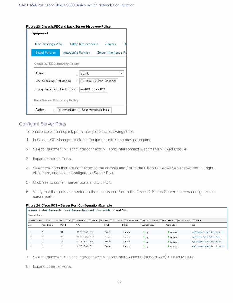
SAP HANA PoD Cisco Nexus 9000 Series Switch Network Configuration
92
Figure 23 Chassis/FEX and Rack Server Discovery Policy
Configure Server Ports
To enable server and uplink ports, complete the following steps:
1. In Cisco UCS Manager, click the Equipment tab in the navigation pane.
2. Select Equipment > Fabric Interconnects > Fabric Interconnect A (primary) > Fixed Module.
3. Expand Ethernet Ports.
4. Select the ports that are connected to the chassis and / or to the Cisco C-Series Server (two per FI), right-
click them, and select Configure as Server Port.
5. Click Yes to confirm server ports and click OK.
6. Verify that the ports connected to the chassis and / or to the Cisco C-Series Server are now configured as
server ports.
Figure 24 Cisco UCS – Server Port Configuration Example
7. Select Equipment > Fabric Interconnects > Fabric Interconnect B (subordinate) > Fixed Module.
8. Expand Ethernet Ports.
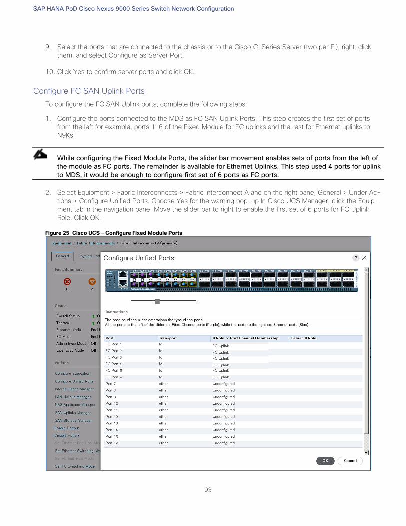
SAP HANA PoD Cisco Nexus 9000 Series Switch Network Configuration
93
9. Select the ports that are connected to the chassis or to the Cisco C-Series Server (two per FI), right-click
them, and select Configure as Server Port.
10. Click Yes to confirm server ports and click OK.
Configure FC SAN Uplink Ports
To configure the FC SAN Uplink ports, complete the following steps:
1. Configure the ports connected to the MDS as FC SAN Uplink Ports. This step creates the first set of ports
from the left for example, ports 1-6 of the Fixed Module for FC uplinks and the rest for Ethernet uplinks to
N9Ks.
While configuring the Fixed Module Ports, the slider bar movement enables sets of ports from the left of
the module as FC ports. The remainder is available for Ethernet Uplinks. This step used 4 ports for uplink
to MDS, it would be enough to configure first set of 6 ports as FC ports.
2. Select Equipment > Fabric Interconnects > Fabric Interconnect A and on the right pane, General > Under Ac-
tions > Configure Unified Ports. Choose Yes for the warning pop-up In Cisco UCS Manager, click the Equip-
ment tab in the navigation pane. Move the slider bar to right to enable the first set of 6 ports for FC Uplink
Role. Click OK.
Figure 25 Cisco UCS – Configure Fixed Module Ports
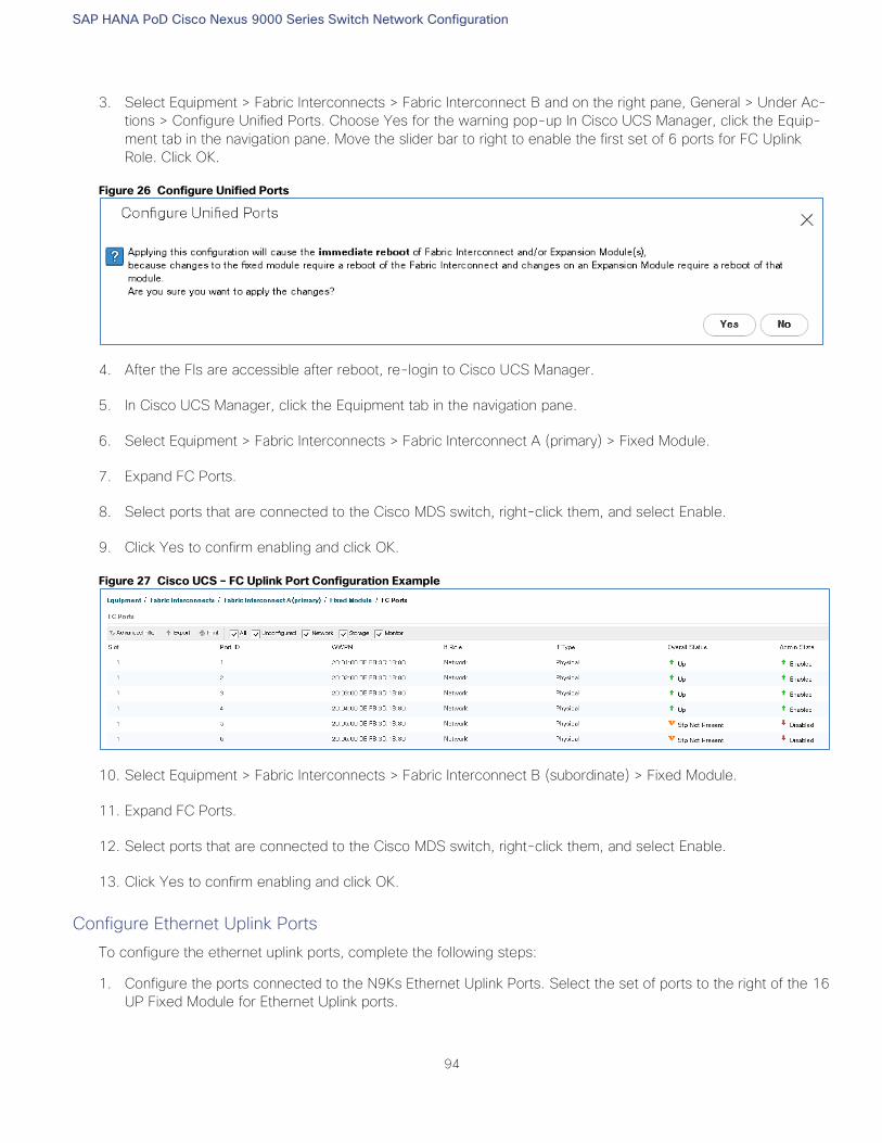
SAP HANA PoD Cisco Nexus 9000 Series Switch Network Configuration
94
3. Select Equipment > Fabric Interconnects > Fabric Interconnect B and on the right pane, General > Under Ac-
tions > Configure Unified Ports. Choose Yes for the warning pop-up In Cisco UCS Manager, click the Equip-
ment tab in the navigation pane. Move the slider bar to right to enable the first set of 6 ports for FC Uplink
Role. Click OK.
Figure 26 Configure Unified Ports
4. After the FIs are accessible after reboot, re-login to Cisco UCS Manager.
5. In Cisco UCS Manager, click the Equipment tab in the navigation pane.
6. Select Equipment > Fabric Interconnects > Fabric Interconnect A (primary) > Fixed Module.
7. Expand FC Ports.
8. Select ports that are connected to the Cisco MDS switch, right-click them, and select Enable.
9. Click Yes to confirm enabling and click OK.
Figure 27 Cisco UCS – FC Uplink Port Configuration Example
10. Select Equipment > Fabric Interconnects > Fabric Interconnect B (subordinate) > Fixed Module.
11. Expand FC Ports.
12. Select ports that are connected to the Cisco MDS switch, right-click them, and select Enable.
13. Click Yes to confirm enabling and click OK.
Configure Ethernet Uplink Ports
To configure the ethernet uplink ports, complete the following steps:
1. Configure the ports connected to the N9Ks Ethernet Uplink Ports. Select the set of ports to the right of the 16
UP Fixed Module for Ethernet Uplink ports.
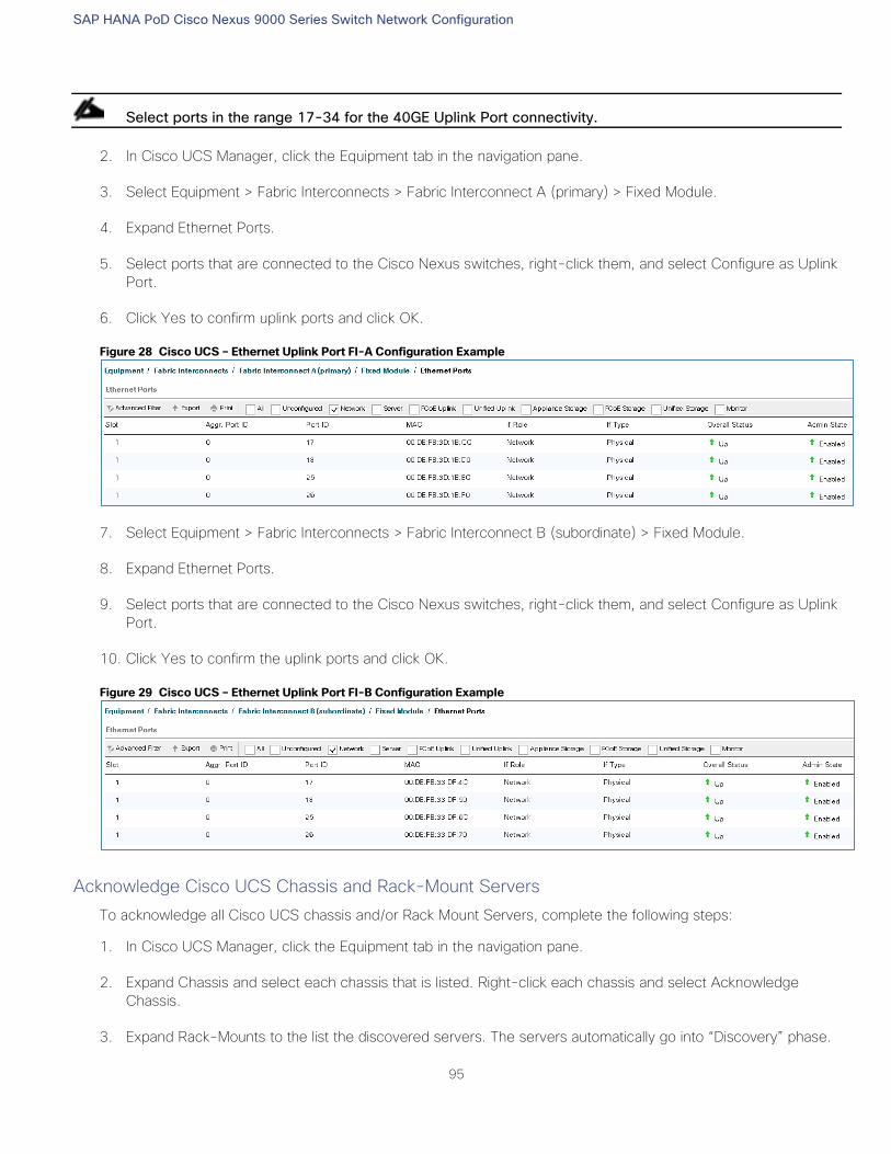
SAP HANA PoD Cisco Nexus 9000 Series Switch Network Configuration
95
Select ports in the range 17-34 for the 40GE Uplink Port connectivity.
2. In Cisco UCS Manager, click the Equipment tab in the navigation pane.
3. Select Equipment > Fabric Interconnects > Fabric Interconnect A (primary) > Fixed Module.
4. Expand Ethernet Ports.
5. Select ports that are connected to the Cisco Nexus switches, right-click them, and select Configure as Uplink
Port.
6. Click Yes to confirm uplink ports and click OK.
Figure 28 Cisco UCS – Ethernet Uplink Port FI-A Configuration Example
7. Select Equipment > Fabric Interconnects > Fabric Interconnect B (subordinate) > Fixed Module.
8. Expand Ethernet Ports.
9. Select ports that are connected to the Cisco Nexus switches, right-click them, and select Configure as Uplink
Port.
10. Click Yes to confirm the uplink ports and click OK.
Figure 29 Cisco UCS – Ethernet Uplink Port FI-B Configuration Example
Acknowledge Cisco UCS Chassis and Rack-Mount Servers
To acknowledge all Cisco UCS chassis and/or Rack Mount Servers, complete the following steps:
1. In Cisco UCS Manager, click the Equipment tab in the navigation pane.
2. Expand Chassis and select each chassis that is listed. Right-click each chassis and select Acknowledge
Chassis.
3. Expand Rack-Mounts to the list the discovered servers. The servers automatically go into “Discovery” phase.
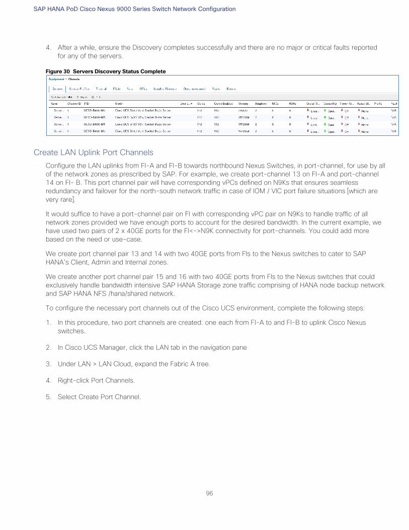
SAP HANA PoD Cisco Nexus 9000 Series Switch Network Configuration
96
4. After a while, ensure the Discovery completes successfully and there are no major or critical faults reported
for any of the servers.
Figure 30 Servers Discovery Status Complete
Create LAN Uplink Port Channels
Configure the LAN uplinks from FI-A and FI-B towards northbound Nexus Switches, in port-channel, for use by all
of the network zones as prescribed by SAP. For example, we create port-channel 13 on FI-A and port-channel
14 on FI- B. This port channel pair will have corresponding vPCs defined on N9Ks that ensures seamless
redundancy and failover for the north-south network traffic in case of IOM / VIC port failure situations [which are
very rare].
It would suffice to have a port-channel pair on FI with corresponding vPC pair on N9Ks to handle traffic of all
network zones provided we have enough ports to account for the desired bandwidth. In the current example, we
have used two pairs of 2 x 40GE ports for the FI<->N9K connectivity for port-channels. You could add more
based on the need or use-case.
We create port channel pair 13 and 14 with two 40GE ports from FIs to the Nexus switches to cater to SAP
HANA’s Client, Admin and Internal zones.
We create another port channel pair 15 and 16 with two 40GE ports from FIs to the Nexus switches that could
exclusively handle bandwidth intensive SAP HANA Storage zone traffic comprising of HANA node backup network
and SAP HANA NFS /hana/shared network.
To configure the necessary port channels out of the Cisco UCS environment, complete the following steps:
1. In this procedure, two port channels are created: one each from FI-A to and FI-B to uplink Cisco Nexus
switches.
2. In Cisco UCS Manager, click the LAN tab in the navigation pane
3. Under LAN > LAN Cloud, expand the Fabric A tree.
4. Right-click Port Channels.
5. Select Create Port Channel.
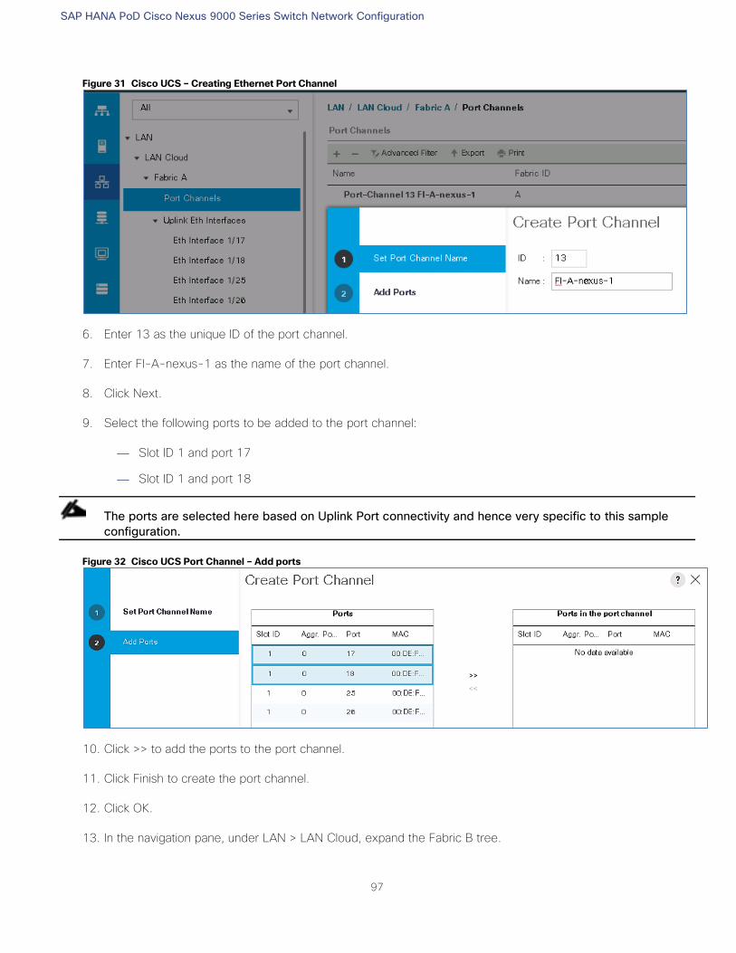
SAP HANA PoD Cisco Nexus 9000 Series Switch Network Configuration
97
Figure 31 Cisco UCS – Creating Ethernet Port Channel
6. Enter 13 as the unique ID of the port channel.
7. Enter FI-A-nexus-1 as the name of the port channel.
8. Click Next.
9. Select the following ports to be added to the port channel:
— Slot ID 1 and port 17
— Slot ID 1 and port 18
The ports are selected here based on Uplink Port connectivity and hence very specific to this sample
configuration.
Figure 32 Cisco UCS Port Channel – Add ports
10. Click >> to add the ports to the port channel.
11. Click Finish to create the port channel.
12. Click OK.
13. In the navigation pane, under LAN > LAN Cloud, expand the Fabric B tree.
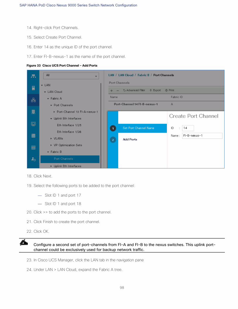
SAP HANA PoD Cisco Nexus 9000 Series Switch Network Configuration
98
14. Right-click Port Channels.
15. Select Create Port Channel.
16. Enter 14 as the unique ID of the port channel.
17. Enter FI-B-nexus-1 as the name of the port channel.
Figure 33 Cisco UCS Port Channel – Add Ports
18. Click Next.
19. Select the following ports to be added to the port channel:
— Slot ID 1 and port 17
— Slot ID 1 and port 18
20. Click >> to add the ports to the port channel.
21. Click Finish to create the port channel.
22. Click OK.
Configure a second set of port-channels from FI-A and FI-B to the nexus switches. This uplink port-
channel could be exclusively used for backup network traffic.
23. In Cisco UCS Manager, click the LAN tab in the navigation pane
24. Under LAN > LAN Cloud, expand the Fabric A tree.
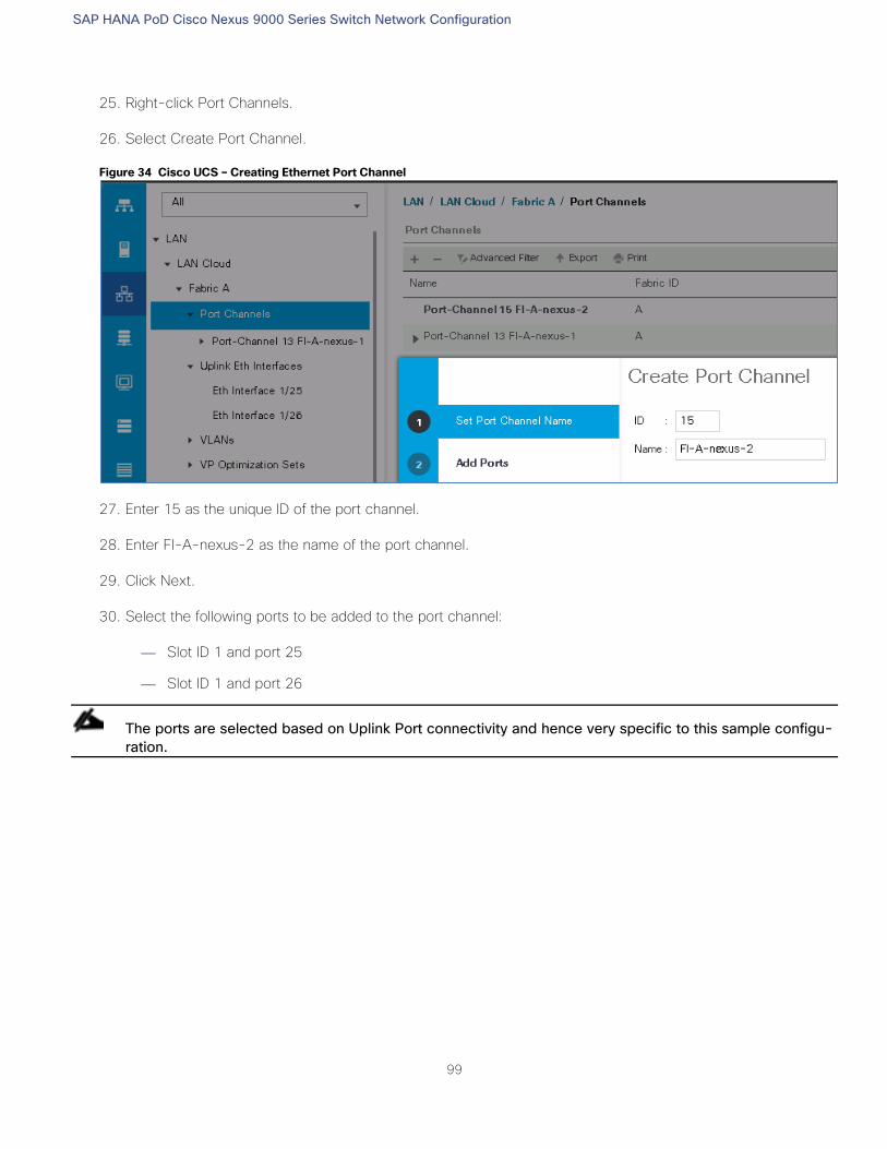
SAP HANA PoD Cisco Nexus 9000 Series Switch Network Configuration
99
25. Right-click Port Channels.
26. Select Create Port Channel.
Figure 34 Cisco UCS – Creating Ethernet Port Channel
27. Enter 15 as the unique ID of the port channel.
28. Enter FI-A-nexus-2 as the name of the port channel.
29. Click Next.
30. Select the following ports to be added to the port channel:
— Slot ID 1 and port 25
— Slot ID 1 and port 26
The ports are selected based on Uplink Port connectivity and hence very specific to this sample configu-
ration.
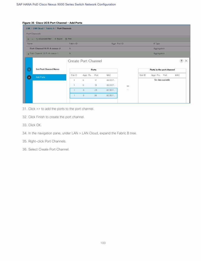
SAP HANA PoD Cisco Nexus 9000 Series Switch Network Configuration
100
Figure 35 Cisco UCS Port Channel – Add Ports
31. Click >> to add the ports to the port channel.
32. Click Finish to create the port channel.
33. Click OK.
34. In the navigation pane, under LAN > LAN Cloud, expand the Fabric B tree.
35. Right-click Port Channels.
36. Select Create Port Channel.
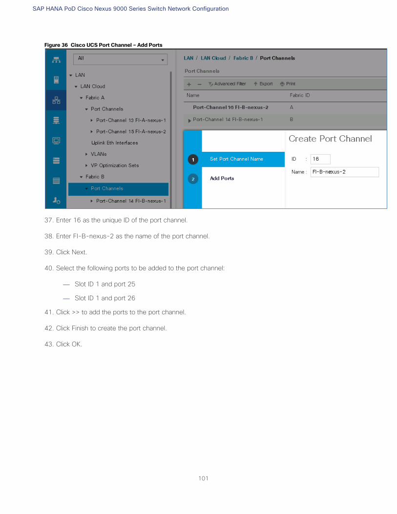
SAP HANA PoD Cisco Nexus 9000 Series Switch Network Configuration
101
Figure 36 Cisco UCS Port Channel – Add Ports
37. Enter 16 as the unique ID of the port channel.
38. Enter FI-B-nexus-2 as the name of the port channel.
39. Click Next.
40. Select the following ports to be added to the port channel:
— Slot ID 1 and port 25
— Slot ID 1 and port 26
41. Click >> to add the ports to the port channel.
42. Click Finish to create the port channel.
43. Click OK.
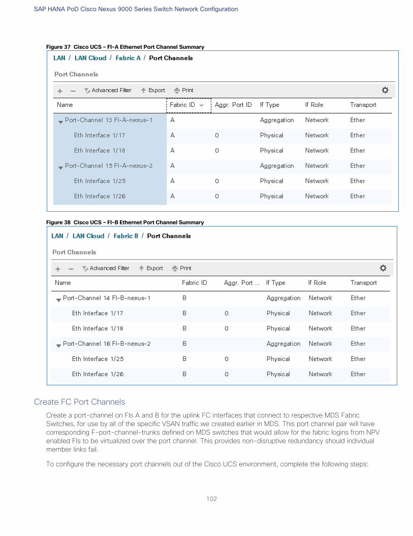
SAP HANA PoD Cisco Nexus 9000 Series Switch Network Configuration
102
Figure 37 Cisco UCS – FI-A Ethernet Port Channel Summary
Figure 38 Cisco UCS – FI-B Ethernet Port Channel Summary
Create FC Port Channels
Create a port-channel on FIs A and B for the uplink FC interfaces that connect to respective MDS Fabric
Switches, for use by all of the specific VSAN traffic we created earlier in MDS. This port channel pair will have
corresponding F-port-channel-trunks defined on MDS switches that would allow for the fabric logins from NPV
enabled FIs to be virtualized over the port channel. This provides non-disruptive redundancy should individual
member links fail.
To configure the necessary port channels out of the Cisco UCS environment, complete the following steps:
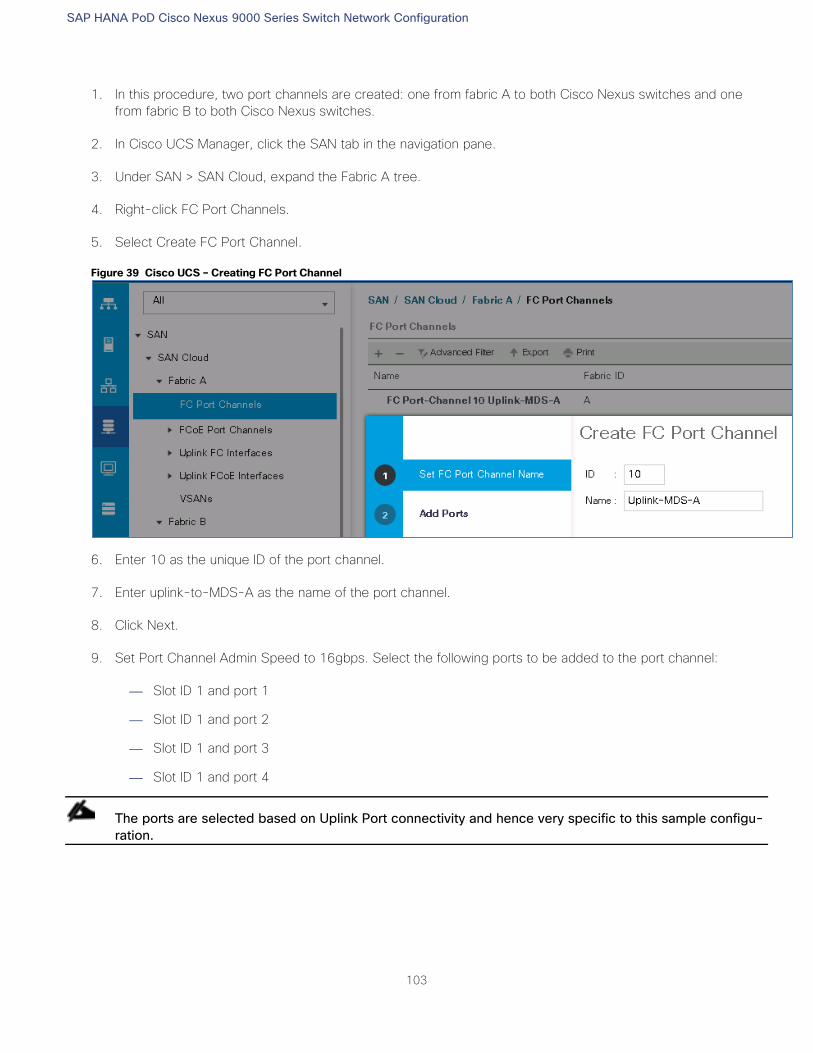
SAP HANA PoD Cisco Nexus 9000 Series Switch Network Configuration
103
1. In this procedure, two port channels are created: one from fabric A to both Cisco Nexus switches and one
from fabric B to both Cisco Nexus switches.
2. In Cisco UCS Manager, click the SAN tab in the navigation pane.
3. Under SAN > SAN Cloud, expand the Fabric A tree.
4. Right-click FC Port Channels.
5. Select Create FC Port Channel.
Figure 39 Cisco UCS – Creating FC Port Channel
6. Enter 10 as the unique ID of the port channel.
7. Enter uplink-to-MDS-A as the name of the port channel.
8. Click Next.
9. Set Port Channel Admin Speed to 16gbps. Select the following ports to be added to the port channel:
— Slot ID 1 and port 1
— Slot ID 1 and port 2
— Slot ID 1 and port 3
— Slot ID 1 and port 4
The ports are selected based on Uplink Port connectivity and hence very specific to this sample configu-
ration.
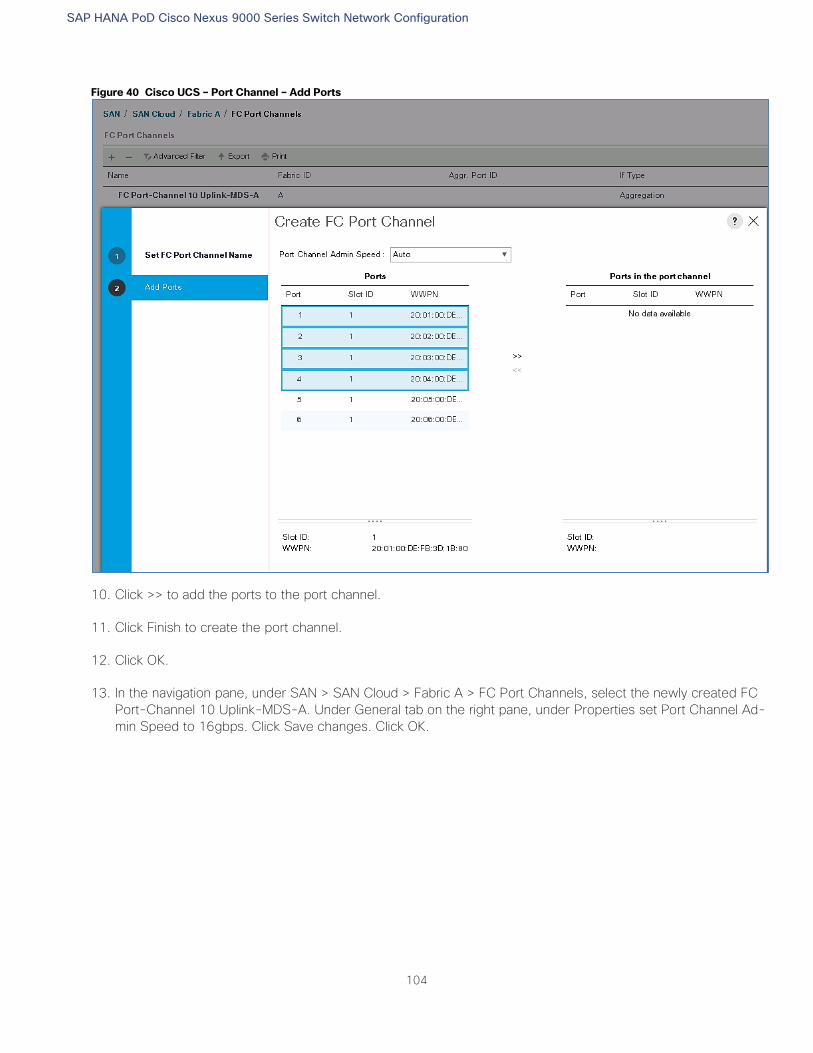
SAP HANA PoD Cisco Nexus 9000 Series Switch Network Configuration
104
Figure 40 Cisco UCS – Port Channel – Add Ports
10. Click >> to add the ports to the port channel.
11. Click Finish to create the port channel.
12. Click OK.
13. In the navigation pane, under SAN > SAN Cloud > Fabric A > FC Port Channels, select the newly created FC
Port-Channel 10 Uplink-MDS-A. Under General tab on the right pane, under Properties set Port Channel Ad-
min Speed to 16gbps. Click Save changes. Click OK.
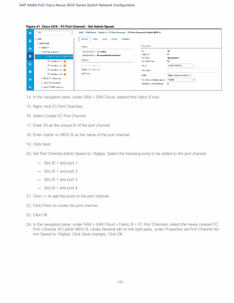
SAP HANA PoD Cisco Nexus 9000 Series Switch Network Configuration
105
Figure 41 Cisco UCS – FC Port Channel – Set Admin Speed
14. In the navigation pane, under SAN > SAN Cloud, expand the Fabric B tree.
15. Right-click FC Port Channels.
16. Select Create FC Port Channel.
17. Enter 20 as the unique ID of the port channel.
18. Enter Uplink-to-MDS-B as the name of the port channel.
19. Click Next.
20. Set Port Channel Admin Speed to 16gbps. Select the following ports to be added to the port channel:
— Slot ID 1 and port 1
— Slot ID 1 and port 2
— Slot ID 1 and port 3
— Slot ID 1 and port 4
21. Click >> to add the ports to the port channel.
22. Click Finish to create the port channel.
23. Click OK.
24. In the navigation pane, under SAN > SAN Cloud > Fabric B > FC Port Channels, select the newly created FC
Port-Channel 20 Uplink-MDS-B. Under General tab on the right pane, under Properties set Port Channel Ad-
min Speed to 16gbps. Click Save changes. Click OK.
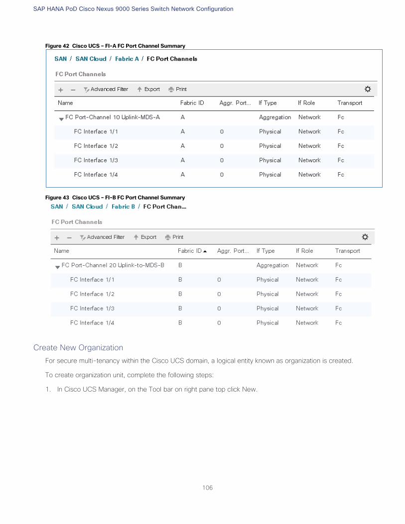
SAP HANA PoD Cisco Nexus 9000 Series Switch Network Configuration
106
Figure 42 Cisco UCS – FI-A FC Port Channel Summary
Figure 43 Cisco UCS – FI-B FC Port Channel Summary
Create New Organization
For secure multi-tenancy within the Cisco UCS domain, a logical entity known as organization is created.
To create organization unit, complete the following steps:
1. In Cisco UCS Manager, on the Tool bar on right pane top click New.
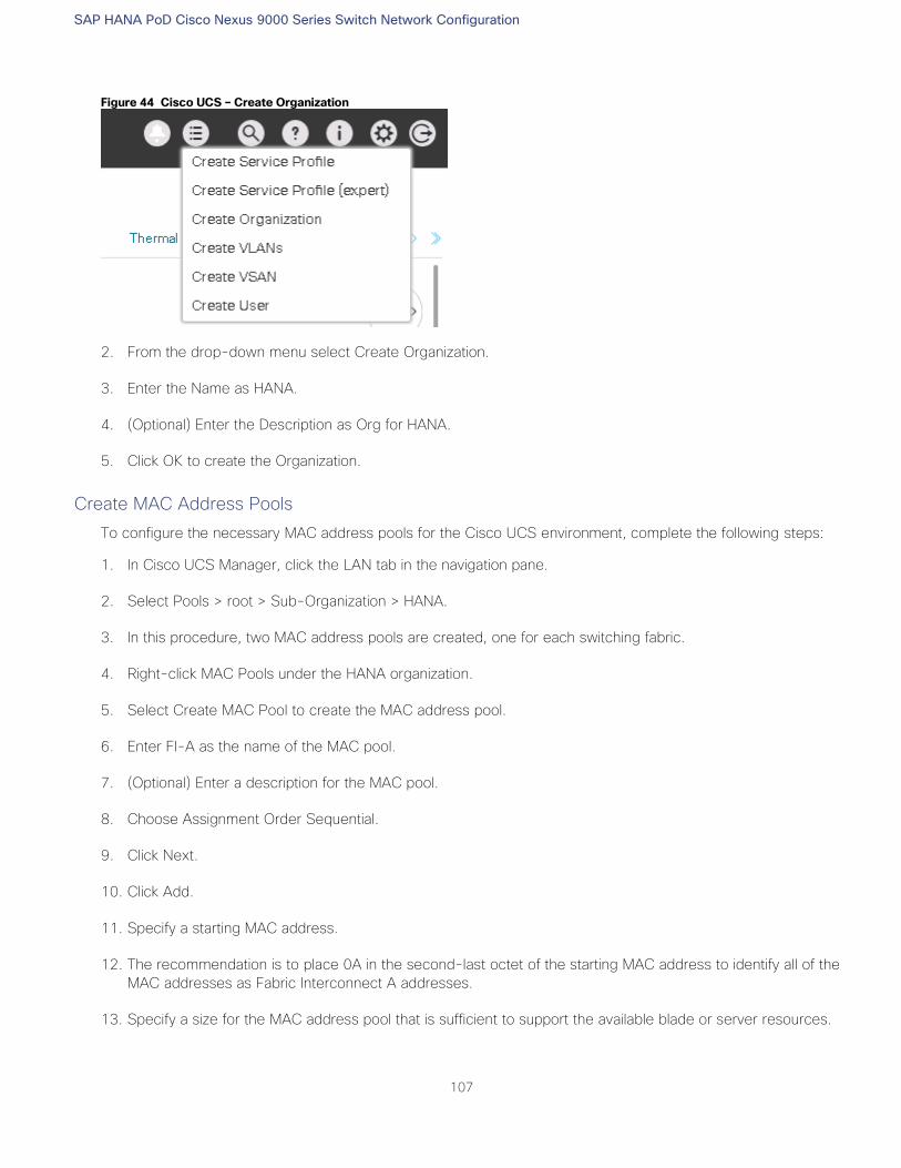
SAP HANA PoD Cisco Nexus 9000 Series Switch Network Configuration
107
Figure 44 Cisco UCS – Create Organization
2. From the drop-down menu select Create Organization.
3. Enter the Name as HANA.
4. (Optional) Enter the Description as Org for HANA.
5. Click OK to create the Organization.
Create MAC Address Pools
To configure the necessary MAC address pools for the Cisco UCS environment, complete the following steps:
1. In Cisco UCS Manager, click the LAN tab in the navigation pane.
2. Select Pools > root > Sub-Organization > HANA.
3. In this procedure, two MAC address pools are created, one for each switching fabric.
4. Right-click MAC Pools under the HANA organization.
5. Select Create MAC Pool to create the MAC address pool.
6. Enter FI-A as the name of the MAC pool.
7. (Optional) Enter a description for the MAC pool.
8. Choose Assignment Order Sequential.
9. Click Next.
10. Click Add.
11. Specify a starting MAC address.
12. The recommendation is to place 0A in the second-last octet of the starting MAC address to identify all of the
MAC addresses as Fabric Interconnect A addresses.
13. Specify a size for the MAC address pool that is sufficient to support the available blade or server resources.
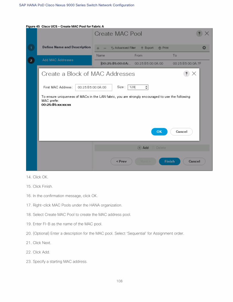
SAP HANA PoD Cisco Nexus 9000 Series Switch Network Configuration
108
Figure 45 Cisco UCS – Create MAC Pool for Fabric A
14. Click OK.
15. Click Finish.
16. In the confirmation message, click OK.
17. Right-click MAC Pools under the HANA organization.
18. Select Create MAC Pool to create the MAC address pool.
19. Enter FI-B as the name of the MAC pool.
20. (Optional) Enter a description for the MAC pool. Select ‘Sequential’ for Assignment order.
21. Click Next.
22. Click Add.
23. Specify a starting MAC address.
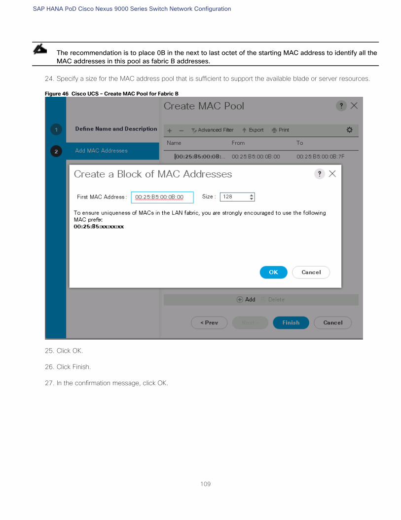
SAP HANA PoD Cisco Nexus 9000 Series Switch Network Configuration
109
The recommendation is to place 0B in the next to last octet of the starting MAC address to identify all the
MAC addresses in this pool as fabric B addresses.
24. Specify a size for the MAC address pool that is sufficient to support the available blade or server resources.
Figure 46 Cisco UCS – Create MAC Pool for Fabric B
25. Click OK.
26. Click Finish.
27. In the confirmation message, click OK.
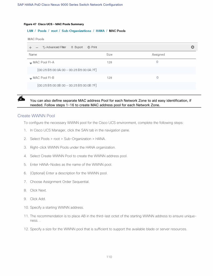
SAP HANA PoD Cisco Nexus 9000 Series Switch Network Configuration
110
Figure 47 Cisco UCS – MAC Pools Summary
You can also define separate MAC address Pool for each Network Zone to aid easy identification, if
needed. Follow steps 1-16 to create MAC address pool for each Network Zone.
Create WWNN Pool
To configure the necessary WWNN pool for the Cisco UCS environment, complete the following steps:
1. In Cisco UCS Manager, click the SAN tab in the navigation pane.
2. Select Pools > root > Sub-Organization > HANA.
3. Right-click WWNN Pools under the HANA organization.
4. Select Create WWNN Pool to create the WWNN address pool.
5. Enter HANA-Nodes as the name of the WWNN pool.
6. (Optional) Enter a description for the WWNN pool.
7. Choose Assignment Order Sequential.
8. Click Next.
9. Click Add.
10. Specify a starting WWNN address.
11. The recommendation is to place AB in the third-last octet of the starting WWNN address to ensure unique-
ness. .
12. Specify a size for the WWNN pool that is sufficient to support the available blade or server resources.
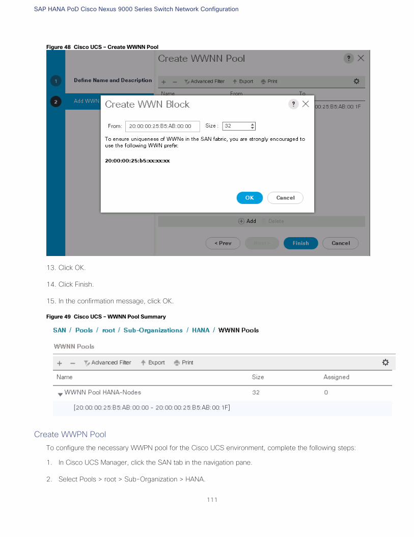
SAP HANA PoD Cisco Nexus 9000 Series Switch Network Configuration
111
Figure 48 Cisco UCS – Create WWNN Pool
13. Click OK.
14. Click Finish.
15. In the confirmation message, click OK.
Figure 49 Cisco UCS – WWNN Pool Summary
Create WWPN Pool
To configure the necessary WWPN pool for the Cisco UCS environment, complete the following steps:
1. In Cisco UCS Manager, click the SAN tab in the navigation pane.
2. Select Pools > root > Sub-Organization > HANA.
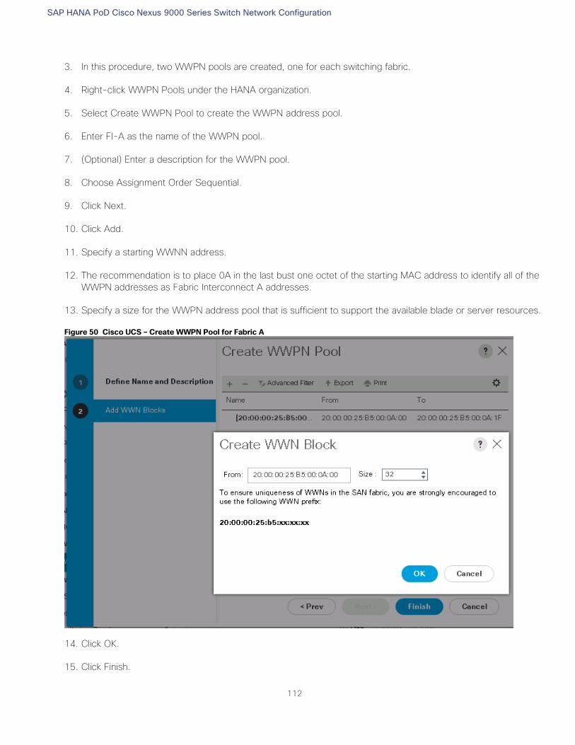
SAP HANA PoD Cisco Nexus 9000 Series Switch Network Configuration
112
3. In this procedure, two WWPN pools are created, one for each switching fabric.
4. Right-click WWPN Pools under the HANA organization.
5. Select Create WWPN Pool to create the WWPN address pool.
6. Enter FI-A as the name of the WWPN pool.
7. (Optional) Enter a description for the WWPN pool.
8. Choose Assignment Order Sequential.
9. Click Next.
10. Click Add.
11. Specify a starting WWNN address.
12. The recommendation is to place 0A in the last bust one octet of the starting MAC address to identify all of the
WWPN addresses as Fabric Interconnect A addresses.
13. Specify a size for the WWPN address pool that is sufficient to support the available blade or server resources.
Figure 50 Cisco UCS – Create WWPN Pool for Fabric A
14. Click OK.
15. Click Finish.
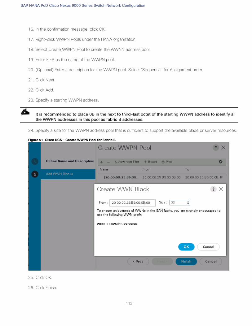
SAP HANA PoD Cisco Nexus 9000 Series Switch Network Configuration
113
16. In the confirmation message, click OK.
17. Right-click WWPN Pools under the HANA organization.
18. Select Create WWPN Pool to create the WWNN address pool.
19. Enter FI-B as the name of the WWPN pool.
20. (Optional) Enter a description for the WWPN pool. Select ‘Sequential’ for Assignment order.
21. Click Next.
22. Click Add.
23. Specify a starting WWPN address.
It is recommended to place 0B in the next to third-last octet of the starting WWPN address to identify all
the WWPN addresses in this pool as fabric B addresses.
24. Specify a size for the WWPN address pool that is sufficient to support the available blade or server resources.
Figure 51 Cisco UCS – Create WWPN Pool for Fabric B
25. Click OK.
26. Click Finish.
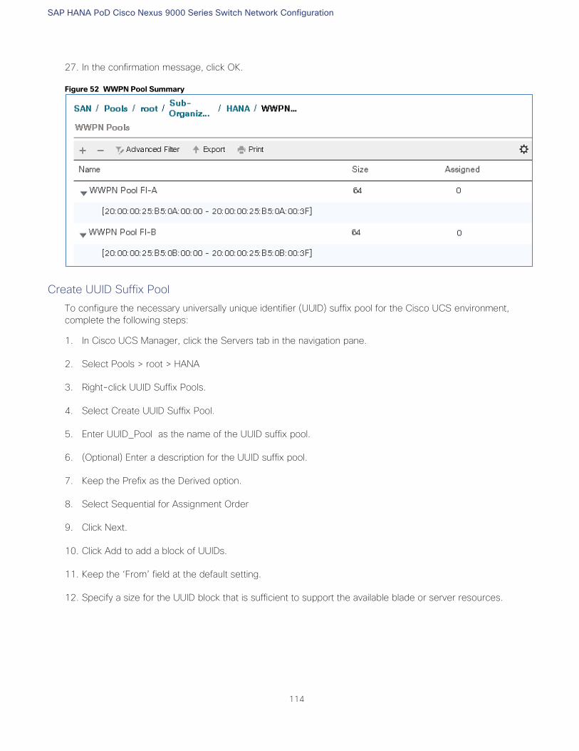
SAP HANA PoD Cisco Nexus 9000 Series Switch Network Configuration
114
27. In the confirmation message, click OK.
Figure 52 WWPN Pool Summary
Create UUID Suffix Pool
To configure the necessary universally unique identifier (UUID) suffix pool for the Cisco UCS environment,
complete the following steps:
1. In Cisco UCS Manager, click the Servers tab in the navigation pane.
2. Select Pools > root > HANA
3. Right-click UUID Suffix Pools.
4. Select Create UUID Suffix Pool.
5. Enter UUID_Pool as the name of the UUID suffix pool.
6. (Optional) Enter a description for the UUID suffix pool.
7. Keep the Prefix as the Derived option.
8. Select Sequential for Assignment Order
9. Click Next.
10. Click Add to add a block of UUIDs.
11. Keep the ‘From’ field at the default setting.
12. Specify a size for the UUID block that is sufficient to support the available blade or server resources.
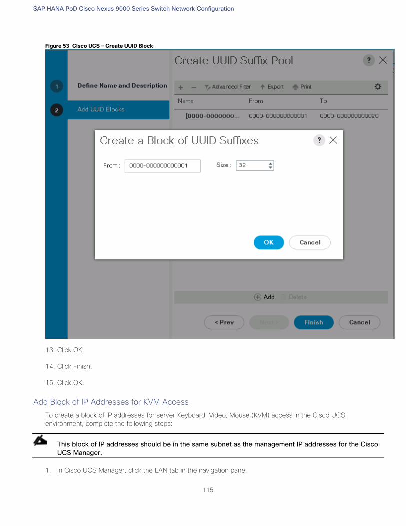
SAP HANA PoD Cisco Nexus 9000 Series Switch Network Configuration
115
Figure 53 Cisco UCS – Create UUID Block
13. Click OK.
14. Click Finish.
15. Click OK.
Add Block of IP Addresses for KVM Access
To create a block of IP addresses for server Keyboard, Video, Mouse (KVM) access in the Cisco UCS
environment, complete the following steps:
This block of IP addresses should be in the same subnet as the management IP addresses for the Cisco
UCS Manager.
1. In Cisco UCS Manager, click the LAN tab in the navigation pane.
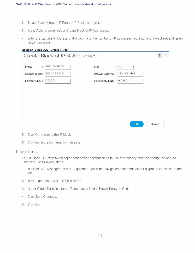
SAP HANA PoD Cisco Nexus 9000 Series Switch Network Configuration
116
2. Select Pools > root > IP Pools > IP Pool ext-mgmt.
3. In the Actions pane, select Create Block of IP Addresses.
4. Enter the starting IP address of the block and the number of IP addresses required, and the subnet and gate-
way information.
Figure 54 Cisco UCS - Create IP Pool
5. Click OK to create the IP block.
6. Click OK in the confirmation message.
Power Policy
To run Cisco UCS with two independent power distribution units, the redundancy must be configured as Grid.
Complete the following steps:
1. In Cisco UCS Manager, click the Equipment tab in the navigation pane and select Equipment in the list on the
left.
2. In the right pane, click the Policies tab.
3. Under Global Policies, set the Redundancy field in Power Policy to Grid.
4. Click Save Changes.
5. Click OK.

SAP HANA PoD Cisco Nexus 9000 Series Switch Network Configuration
117
Figure 55 Power Policy
Power Control Policy
The Power Capping feature in Cisco UCS is designed to save power with a legacy data center use cases. This
feature does not contribute much to the high performance behavior of SAP HANA. By choosing the option “No
Cap” for power control policy, the SAP HANA server nodes will not have a restricted power supply. It is
recommended to have this power control policy to make sure sufficient power supply for high performance and
critical applications like SAP HANA.
To create a power control policy for the Cisco UCS environment, complete the following steps:
1. In Cisco UCS Manager, click the Servers tab in the navigation pane.
2. Select Policies > root.
3. Right-click Power Control Policies.
4. Select Create Power Control Policy.
5. Enter HANA as the Power Control Policy name. (Optional) provide description.
6. Set Fan Speed Policy to Performance.
7. Change the Power Capping setting to No Cap.
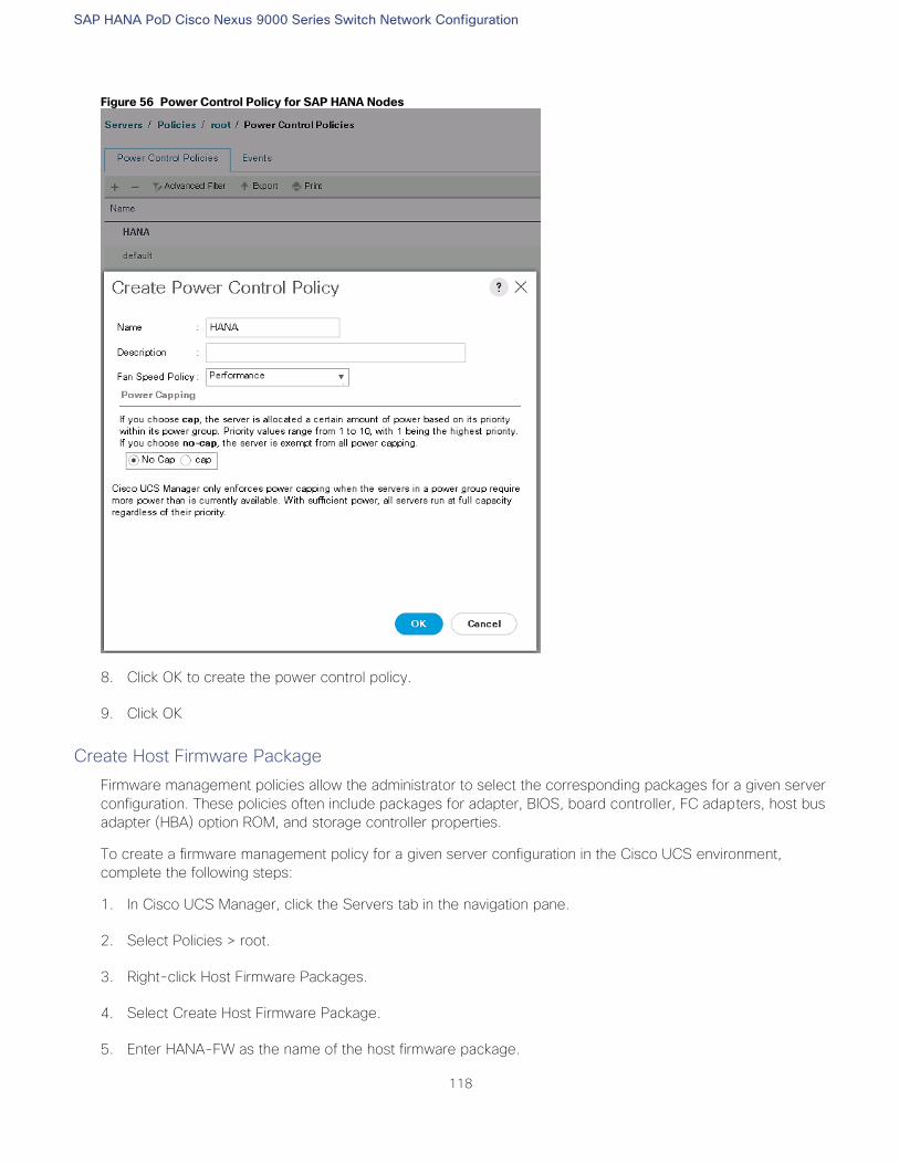
SAP HANA PoD Cisco Nexus 9000 Series Switch Network Configuration
118
Figure 56 Power Control Policy for SAP HANA Nodes
8. Click OK to create the power control policy.
9. Click OK
Create Host Firmware Package
Firmware management policies allow the administrator to select the corresponding packages for a given server
configuration. These policies often include packages for adapter, BIOS, board controller, FC adapters, host bus
adapter (HBA) option ROM, and storage controller properties.
To create a firmware management policy for a given server configuration in the Cisco UCS environment,
complete the following steps:
1. In Cisco UCS Manager, click the Servers tab in the navigation pane.
2. Select Policies > root.
3. Right-click Host Firmware Packages.
4. Select Create Host Firmware Package.
5. Enter HANA-FW as the name of the host firmware package.
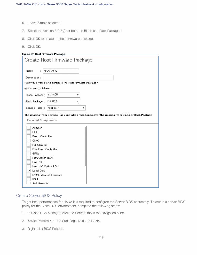
SAP HANA PoD Cisco Nexus 9000 Series Switch Network Configuration
119
6. Leave Simple selected.
7. Select the version 3.2(3g) for both the Blade and Rack Packages.
8. Click OK to create the host firmware package.
9. Click OK.
Figure 57 Host Firmware Package
Create Server BIOS Policy
To get best performance for HANA it is required to configure the Server BIOS accurately. To create a server BIOS
policy for the Cisco UCS environment, complete the following steps:
1. In Cisco UCS Manager, click the Servers tab in the navigation pane.
2. Select Policies > root > Sub-Organization > HANA.
3. Right-click BIOS Policies.
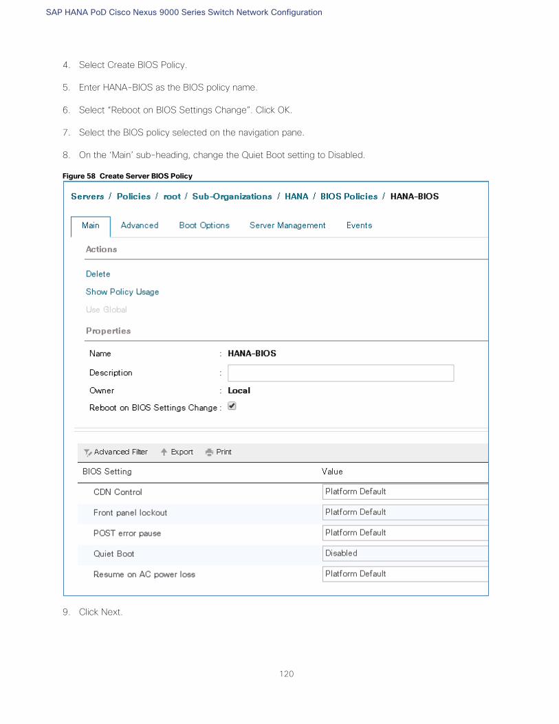
SAP HANA PoD Cisco Nexus 9000 Series Switch Network Configuration
120
4. Select Create BIOS Policy.
5. Enter HANA-BIOS as the BIOS policy name.
6. Select “Reboot on BIOS Settings Change”. Click OK.
7. Select the BIOS policy selected on the navigation pane.
8. On the ‘Main’ sub-heading, change the Quiet Boot setting to Disabled.
Figure 58 Create Server BIOS Policy
9. Click Next.
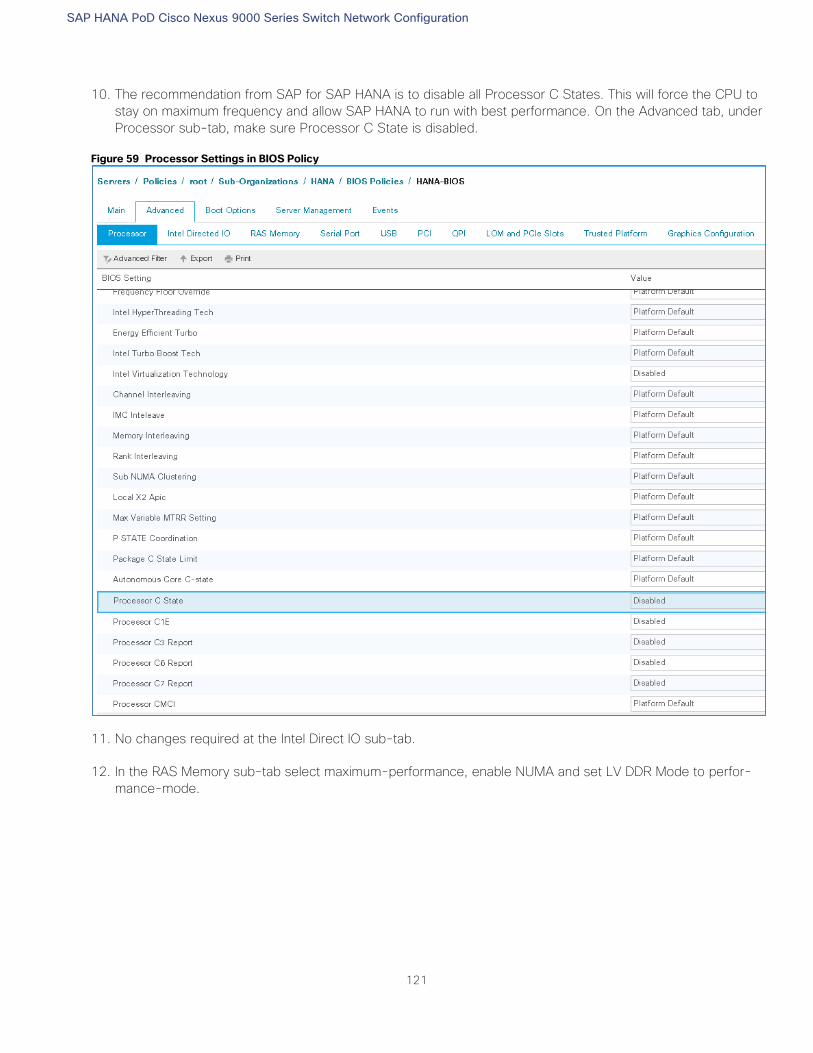
SAP HANA PoD Cisco Nexus 9000 Series Switch Network Configuration
121
10. The recommendation from SAP for SAP HANA is to disable all Processor C States. This will force the CPU to
stay on maximum frequency and allow SAP HANA to run with best performance. On the Advanced tab, under
Processor sub-tab, make sure Processor C State is disabled.
Figure 59 Processor Settings in BIOS Policy
11. No changes required at the Intel Direct IO sub-tab.
12. In the RAS Memory sub-tab select maximum-performance, enable NUMA and set LV DDR Mode to perfor-
mance-mode.
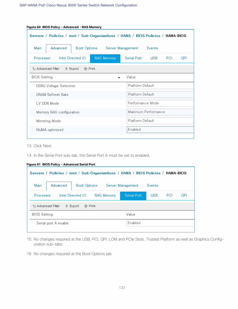
SAP HANA PoD Cisco Nexus 9000 Series Switch Network Configuration
122
Figure 60 BIOS Policy – Advanced - RAS Memory
13. Click Next.
14. In the Serial Port sub-tab, the Serial Port A must be set to enabled.
Figure 61 BIOS Policy – Advanced Serial Port
15. No changes required at the USB, PCI, QPI, LOM and PCIe Slots, Trusted Platform as well as Graphics Config-
uration sub-tabs.
16. No changes required at the Boot Options tab.
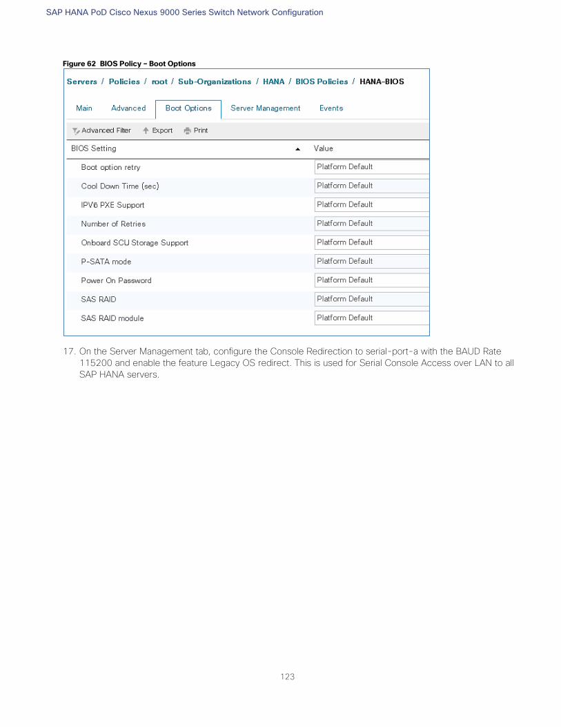
SAP HANA PoD Cisco Nexus 9000 Series Switch Network Configuration
123
Figure 62 BIOS Policy – Boot Options
17. On the Server Management tab, configure the Console Redirection to serial-port-a with the BAUD Rate
115200 and enable the feature Legacy OS redirect. This is used for Serial Console Access over LAN to all
SAP HANA servers.
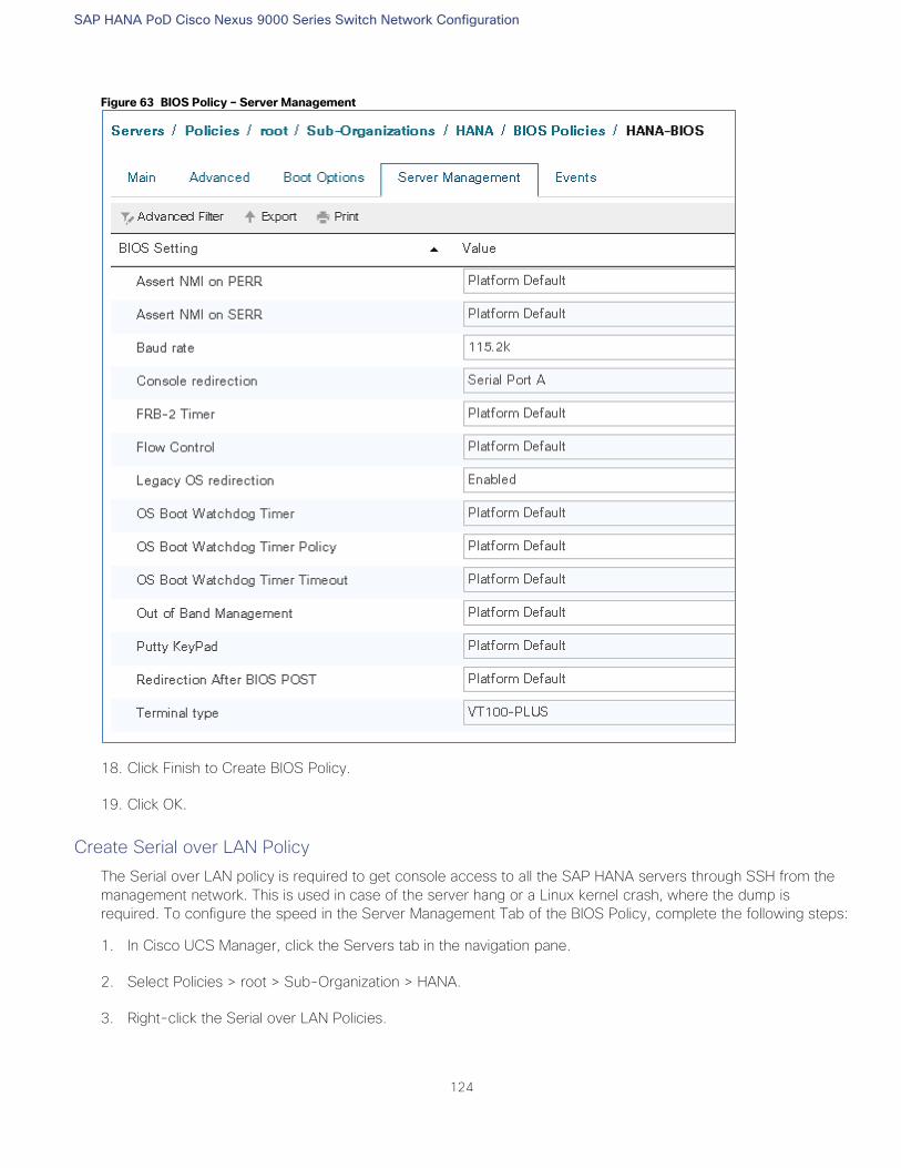
SAP HANA PoD Cisco Nexus 9000 Series Switch Network Configuration
124
Figure 63 BIOS Policy – Server Management
18. Click Finish to Create BIOS Policy.
19. Click OK.
Create Serial over LAN Policy
The Serial over LAN policy is required to get console access to all the SAP HANA servers through SSH from the
management network. This is used in case of the server hang or a Linux kernel crash, where the dump is
required. To configure the speed in the Server Management Tab of the BIOS Policy, complete the following steps:
1. In Cisco UCS Manager, click the Servers tab in the navigation pane.
2. Select Policies > root > Sub-Organization > HANA.
3. Right-click the Serial over LAN Policies.
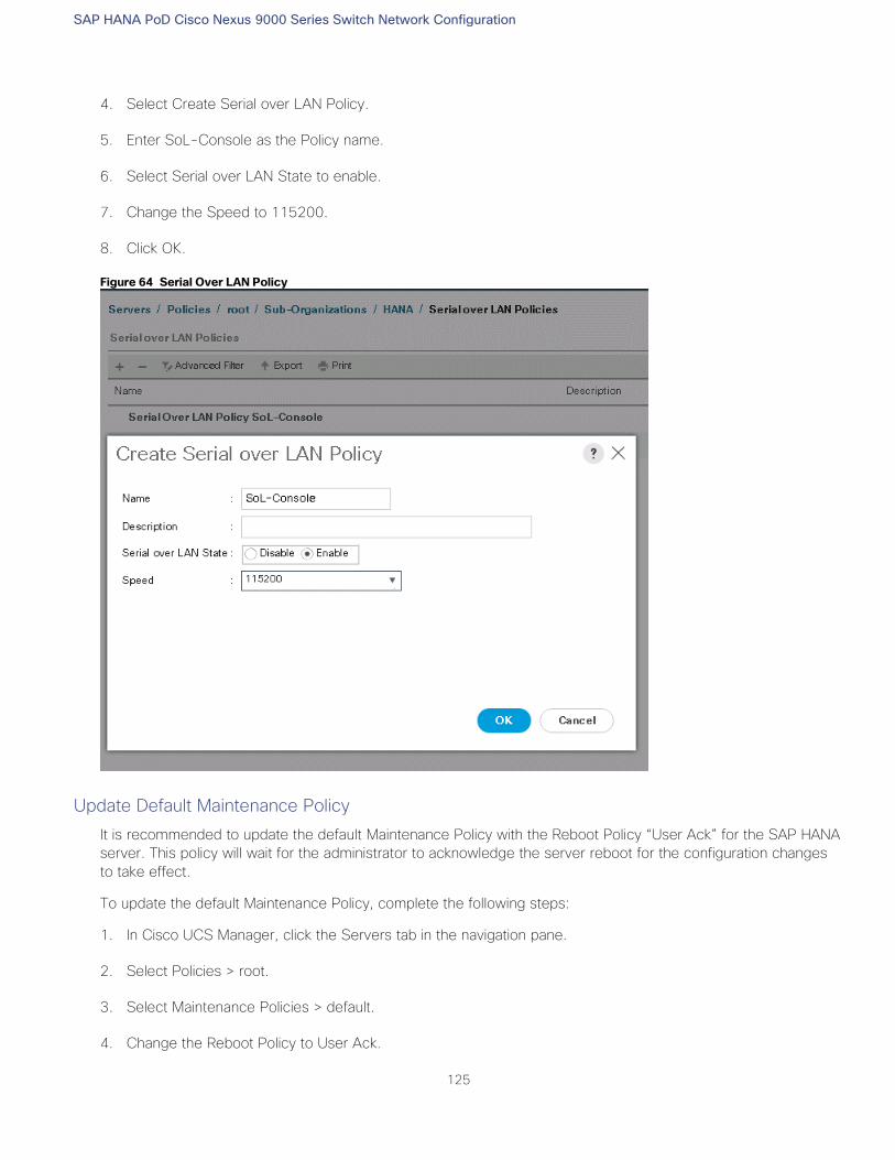
SAP HANA PoD Cisco Nexus 9000 Series Switch Network Configuration
125
4. Select Create Serial over LAN Policy.
5. Enter SoL-Console as the Policy name.
6. Select Serial over LAN State to enable.
7. Change the Speed to 115200.
8. Click OK.
Figure 64 Serial Over LAN Policy
Update Default Maintenance Policy
It is recommended to update the default Maintenance Policy with the Reboot Policy “User Ack” for the SAP HANA
server. This policy will wait for the administrator to acknowledge the server reboot for the configuration changes
to take effect.
To update the default Maintenance Policy, complete the following steps:
1. In Cisco UCS Manager, click the Servers tab in the navigation pane.
2. Select Policies > root.
3. Select Maintenance Policies > default.
4. Change the Reboot Policy to User Ack.
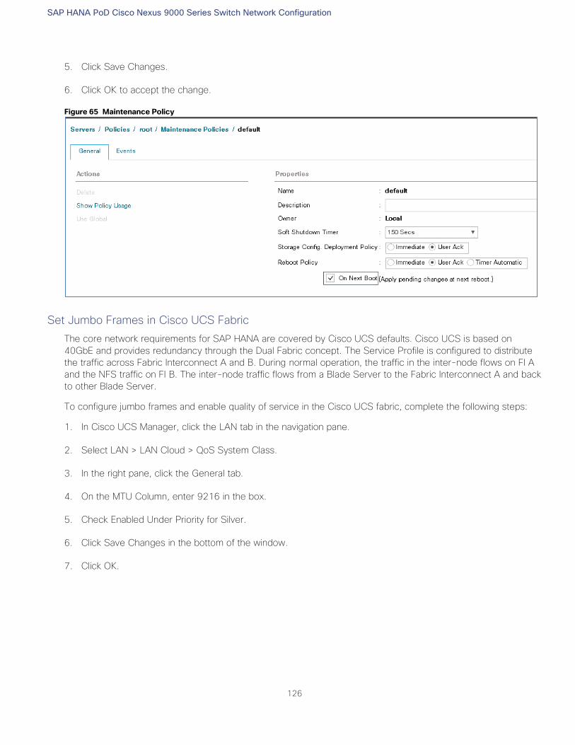
SAP HANA PoD Cisco Nexus 9000 Series Switch Network Configuration
126
5. Click Save Changes.
6. Click OK to accept the change.
Figure 65 Maintenance Policy
Set Jumbo Frames in Cisco UCS Fabric
The core network requirements for SAP HANA are covered by Cisco UCS defaults. Cisco UCS is based on
40GbE and provides redundancy through the Dual Fabric concept. The Service Profile is configured to distribute
the traffic across Fabric Interconnect A and B. During normal operation, the traffic in the inter-node flows on FI A
and the NFS traffic on FI B. The inter-node traffic flows from a Blade Server to the Fabric Interconnect A and back
to other Blade Server.
To configure jumbo frames and enable quality of service in the Cisco UCS fabric, complete the following steps:
1. In Cisco UCS Manager, click the LAN tab in the navigation pane.
2. Select LAN > LAN Cloud > QoS System Class.
3. In the right pane, click the General tab.
4. On the MTU Column, enter 9216 in the box.
5. Check Enabled Under Priority for Silver.
6. Click Save Changes in the bottom of the window.
7. Click OK.
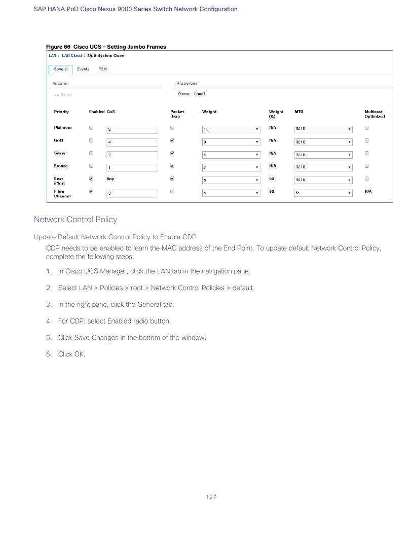
SAP HANA PoD Cisco Nexus 9000 Series Switch Network Configuration
127
Figure 66 Cisco UCS – Setting Jumbo Frames
Network Control Policy
Update Default Network Control Policy to Enable CDP
CDP needs to be enabled to learn the MAC address of the End Point. To update default Network Control Policy,
complete the following steps:
1. In Cisco UCS Manager, click the LAN tab in the navigation pane.
2. Select LAN > Policies > root > Network Control Policies > default.
3. In the right pane, click the General tab.
4. For CDP: select Enabled radio button.
5. Click Save Changes in the bottom of the window.
6. Click OK.
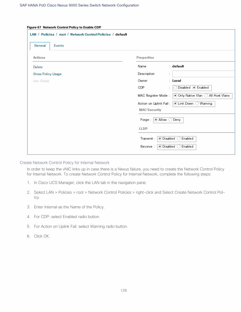
SAP HANA PoD Cisco Nexus 9000 Series Switch Network Configuration
128
Figure 67 Network Control Policy to Enable CDP
Create Network Control Policy for Internal Network
In order to keep the vNIC links up in case there is a Nexus failure, you need to create the Network Control Policy
for Internal Network. To create Network Control Policy for Internal Network, complete the following steps:
1. In Cisco UCS Manager, click the LAN tab in the navigation pane.
2. Select LAN > Policies > root > Network Control Policies > right-click and Select Create Network Control Pol-
icy.
3. Enter Internal as the Name of the Policy.
4. For CDP: select Enabled radio button.
5. For Action on Uplink Fail: select Warning radio button.
6. Click OK.
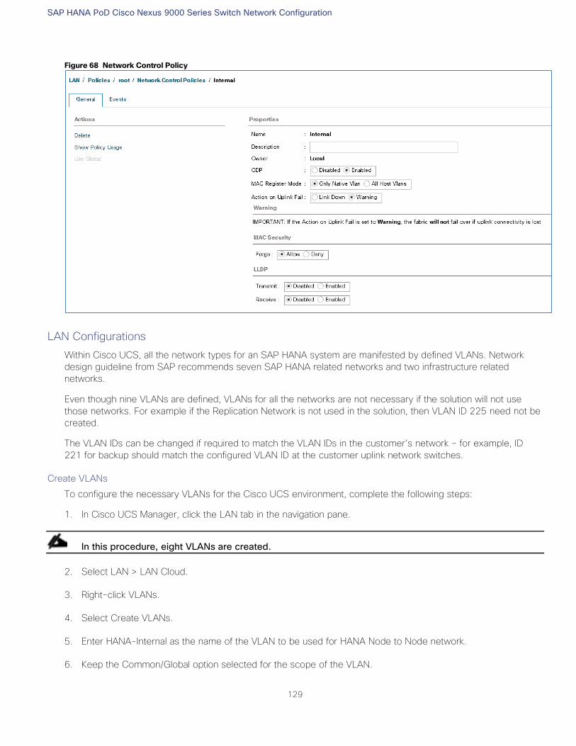
SAP HANA PoD Cisco Nexus 9000 Series Switch Network Configuration
129
Figure 68 Network Control Policy
LAN Configurations
Within Cisco UCS, all the network types for an SAP HANA system are manifested by defined VLANs. Network
design guideline from SAP recommends seven SAP HANA related networks and two infrastructure related
networks.
Even though nine VLANs are defined, VLANs for all the networks are not necessary if the solution will not use
those networks. For example if the Replication Network is not used in the solution, then VLAN ID 225 need not be
created.
The VLAN IDs can be changed if required to match the VLAN IDs in the customer’s network – for example, ID
221 for backup should match the configured VLAN ID at the customer uplink network switches.
Create VLANs
To configure the necessary VLANs for the Cisco UCS environment, complete the following steps:
1. In Cisco UCS Manager, click the LAN tab in the navigation pane.
In this procedure, eight VLANs are created.
2. Select LAN > LAN Cloud.
3. Right-click VLANs.
4. Select Create VLANs.
5. Enter HANA-Internal as the name of the VLAN to be used for HANA Node to Node network.
6. Keep the Common/Global option selected for the scope of the VLAN.
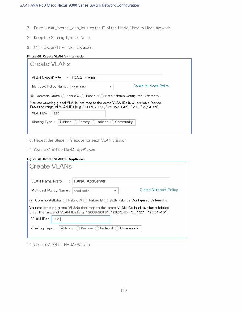
SAP HANA PoD Cisco Nexus 9000 Series Switch Network Configuration
130
7. Enter <<var_internal_vlan_id>> as the ID of the HANA Node to Node network.
8. Keep the Sharing Type as None.
9. Click OK, and then click OK again.
Figure 69 Create VLAN for Internode
10. Repeat the Steps 1-9 above for each VLAN creation.
11. Create VLAN for HANA-AppServer.
Figure 70 Create VLAN for AppServer
12. Create VLAN for HANA-Backup.
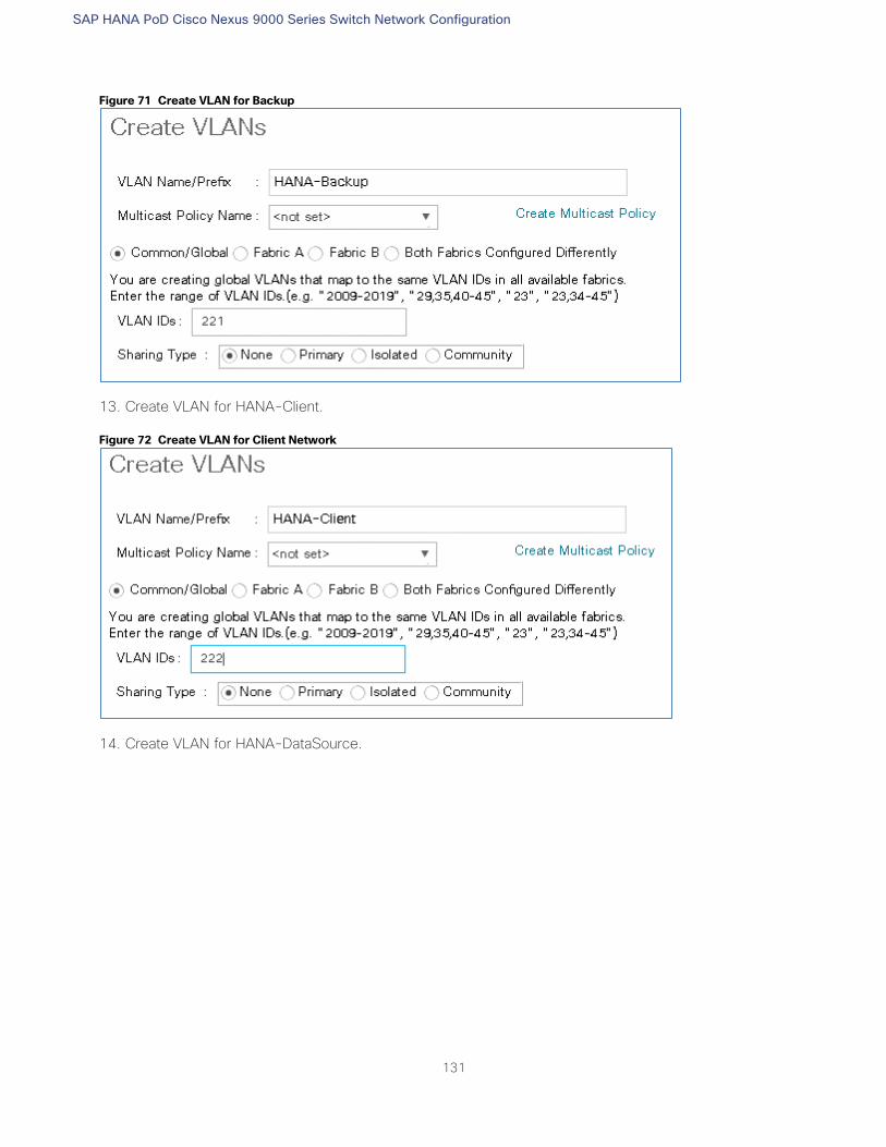
SAP HANA PoD Cisco Nexus 9000 Series Switch Network Configuration
131
Figure 71 Create VLAN for Backup
13. Create VLAN for HANA-Client.
Figure 72 Create VLAN for Client Network
14. Create VLAN for HANA-DataSource.
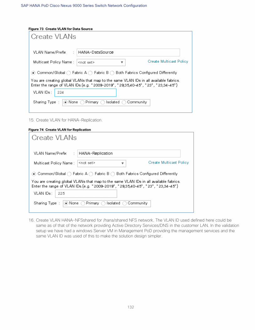
SAP HANA PoD Cisco Nexus 9000 Series Switch Network Configuration
132
Figure 73 Create VLAN for Data Source
15. Create VLAN for HANA-Replication.
Figure 74 Create VLAN for Replication
16. Create VLAN HANA-NFSshared for /hana/shared NFS network. The VLAN ID used defined here could be
same as of that of the network providing Active Directory Services/DNS in the customer LAN. In the validation
setup we have had a windows Server VM in Management PoD providing the management services and the
same VLAN ID was used of this to make the solution design simpler.
SAP HANA PoD Cisco Nexus 9000 Series Switch Network Configuration
133
Figure 75 Create VLAN for /hana/shared NFS Network
17. Create VLAN for Management.
Figure 76 Create VLAN for Management
The list of created VLANs is shown below:
SAP HANA PoD Cisco Nexus 9000 Series Switch Network Configuration
134
Figure 77 VLAN Definition in Cisco UCS
Create VLAN Groups
For easier management and bandwidth allocation to a dedicated uplink on the Fabric Interconnect, VLAN Groups
are created within the Cisco UCS. SAP groups the networks needed by HANA system into following zones which
could be translated to VLAN groups in Cisco UCS configuration:
Client Zone – including AppServer, Client and DataSource networks
Internal Zone – including Inter-node and System Replication networks
Storage Zone – including Backup and IP storage networks
And optional Admin zone – including Management, PXE Boot network, OS cluster network, if any
To configure the necessary VLAN Groups for the Cisco UCS environment, complete the following steps:
1. In Cisco UCS Manager, click the LAN tab in the navigation pane.
In this procedure, three VLAN Groups are created. Based on the solution requirement create VLAN
groups as needed by the implementation scenario.
2. Select LAN > LAN Cloud.
3. Right-click VLAN Groups.
4. Select Create VLAN Groups.
5. Enter Admin-Zone as the name of the VLAN Group used for Infrastructure network.
6. Select HANA-Mgmt.
SAP HANA PoD Cisco Nexus 9000 Series Switch Network Configuration
135
Figure 78 Create VLAN Group for Admin Zone
7. Click Next
8. Click Next on Add Uplink Ports, since you will use port-channel.
9. Choose port-channels created [13 & 14 in this example configuration] for uplink network. Click >>
Figure 79 Add Port-Channel for VLAN Group Admin Zone
10. Click Finish.
11. Create VLAN Group for Client Zone. Select HANA-AppServer, HANA-Client and HANA-DataSource networks
to be part of this VLAN group.
SAP HANA PoD Cisco Nexus 9000 Series Switch Network Configuration
136
Figure 80 Create VLAN Group for Client Zone
12. Click Next.
13. Click Next on Add Uplink Ports, since you will use port-channel.
14. Choose port-channels [13 & 14 in this example configuration] created for uplink network. Click >>
Figure 81 Add Port-Channel for VLAN Group Internal Zone
15. Click Finish.
16. Similarly, create VLAN Group for Internal Zone. Select HANA-Internal network. Optionally select the HANA-
Replication, if used in the setup.
SAP HANA PoD Cisco Nexus 9000 Series Switch Network Configuration
137
Figure 82 Create VLAN Group for Internal Zone
17. Click Next.
18. Click Next on Add Uplink Ports, since you will use port-channel.
19. Choose port-channels (13 and 14 in this example configuration) created for uplink network. Click >>
Figure 83 Add Port-Channel for VLAN Group Internal Zone
20. Click Finish.
21. Similarly, create VLAN Groups for Storage Zone. Select the HANA-NFSshared network. Optionally select
HANA-Backup network, if used in the setup.

SAP HANA PoD Cisco Nexus 9000 Series Switch Network Configuration
138
Figure 84 Create VLAN Group for Storage Zone
22. Click Next.
23. Click Next on Add Uplink Ports, since you will use port-channel.
24. Choose other pair of port-channels (15 and 16 in this example configuration) created for Storage Zone.
Figure 85 Add Port-Channel for VLAN Group Client Zone
25. Click Finish.
26. More VLAN groups, if needed could be created following the above steps. VLAN Groups created in the Cisco
UCS.
SAP HANA PoD Cisco Nexus 9000 Series Switch Network Configuration
139
Figure 86 VLAN Groups in Cisco UCS
For each VLAN Group a dedicated Ethernet Uplink Port or Port Channel can be selected, if the use-case
demands. Alternatively, a single uplink Port Channel with more ports to enhance the bandwidth could
also be used if that suffices.
Create vNIC Template
Each VLAN is mapped to a vNIC template to specify the characteristic of a specific network. The vNIC template
configuration settings include MTU size, Failover capabilities and MAC-Address pools.
To create vNIC templates for the Cisco UCS environment, complete the following steps:
1. In Cisco UCS Manager, click the LAN tab in the navigation pane.
2. Select Policies > root > Sub-Organization > HANA.
3. Right-click vNIC Templates.
4. Select Create vNIC Template.
5. Enter HANA-Internal as the vNIC template name.
6. Keep Fabric A selected.
7. Check the Enable Failover checkbox.
8. Under Target, make sure that the VM checkbox is unchecked.
SAP HANA PoD Cisco Nexus 9000 Series Switch Network Configuration
140
9. Select Updating Template as the Template Type.
10. Under VLANs, check the checkboxes for HANA-Internal.
11. Set HANA-Internal as the native VLAN.
12. For MTU, enter 9000.
13. In the MAC Pool list, select FI-A.
14. For Network Control Policy Select Internal from drop-down list.
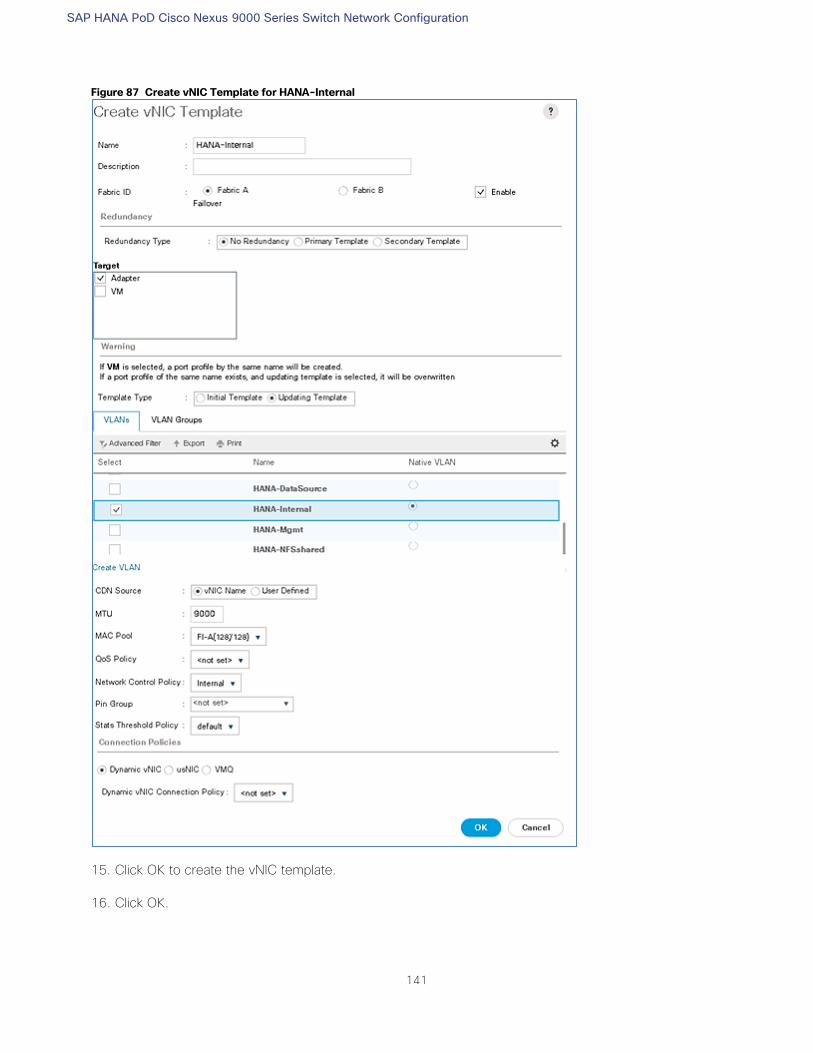
SAP HANA PoD Cisco Nexus 9000 Series Switch Network Configuration
141
Figure 87 Create vNIC Template for HANA-Internal
15. Click OK to create the vNIC template.
16. Click OK.
SAP HANA PoD Cisco Nexus 9000 Series Switch Network Configuration
142
For most SAP HANA use cases the network traffic is well distributed across the two Fabrics (Fabric A
and Fabric B) using the default setup. In special cases, it can be required to rebalance this distribution
for better overall performance. This can be done in the vNIC template with the Fabric ID setting. The
MTU settings must match the configuration in customer data center. MTU setting of 9000 is recom-
mended for best performance.
17. Similarly create vNIC template for each Network.
18. Create a vNIC template for HANA Nodes OS Cluster network.
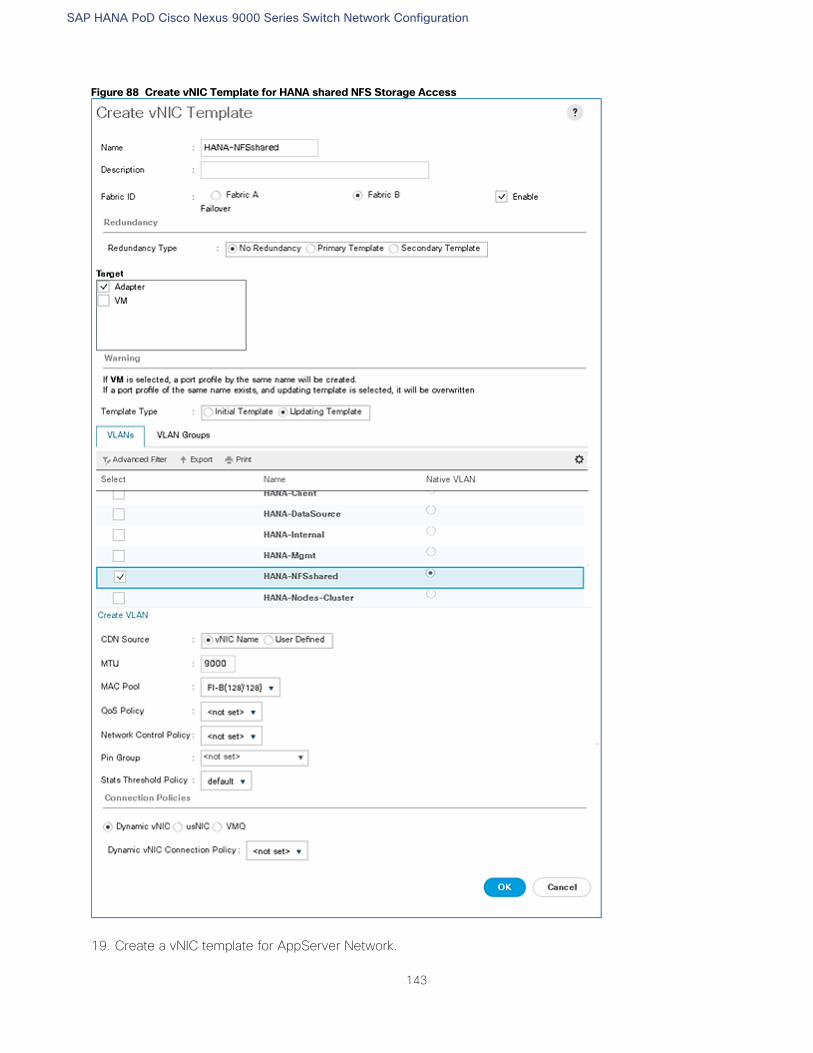
SAP HANA PoD Cisco Nexus 9000 Series Switch Network Configuration
143
Figure 88 Create vNIC Template for HANA shared NFS Storage Access
19. Create a vNIC template for AppServer Network.
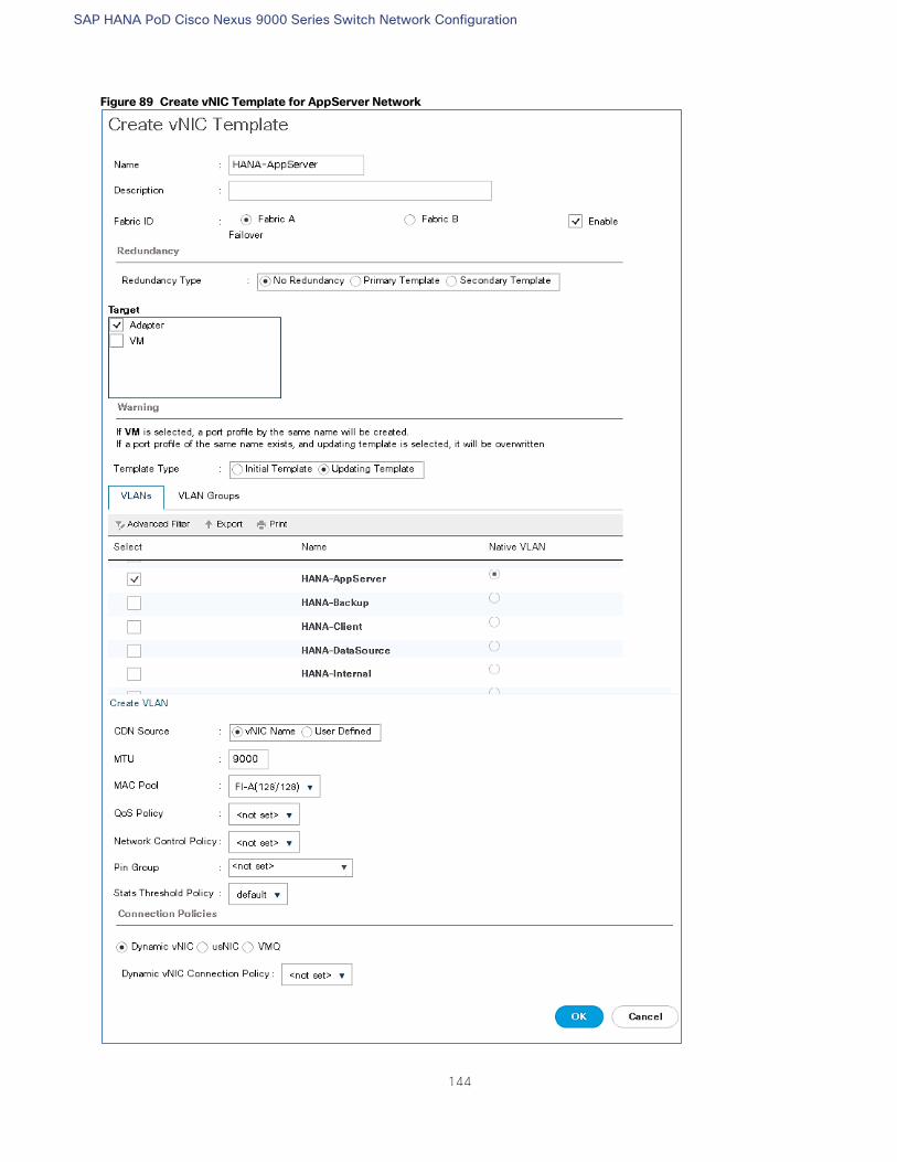
SAP HANA PoD Cisco Nexus 9000 Series Switch Network Configuration
144
Figure 89 Create vNIC Template for AppServer Network
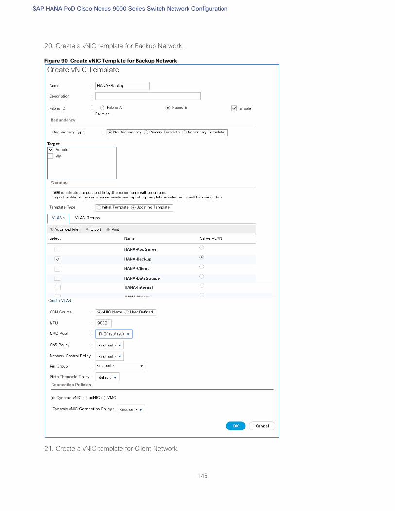
SAP HANA PoD Cisco Nexus 9000 Series Switch Network Configuration
145
20. Create a vNIC template for Backup Network.
Figure 90 Create vNIC Template for Backup Network
21. Create a vNIC template for Client Network.
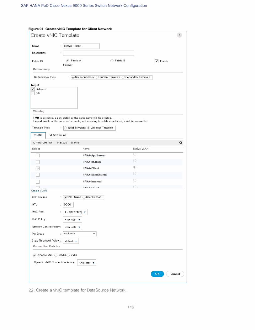
SAP HANA PoD Cisco Nexus 9000 Series Switch Network Configuration
146
Figure 91 Create vNIC Template for Client Network
22. Create a vNIC template for DataSource Network.
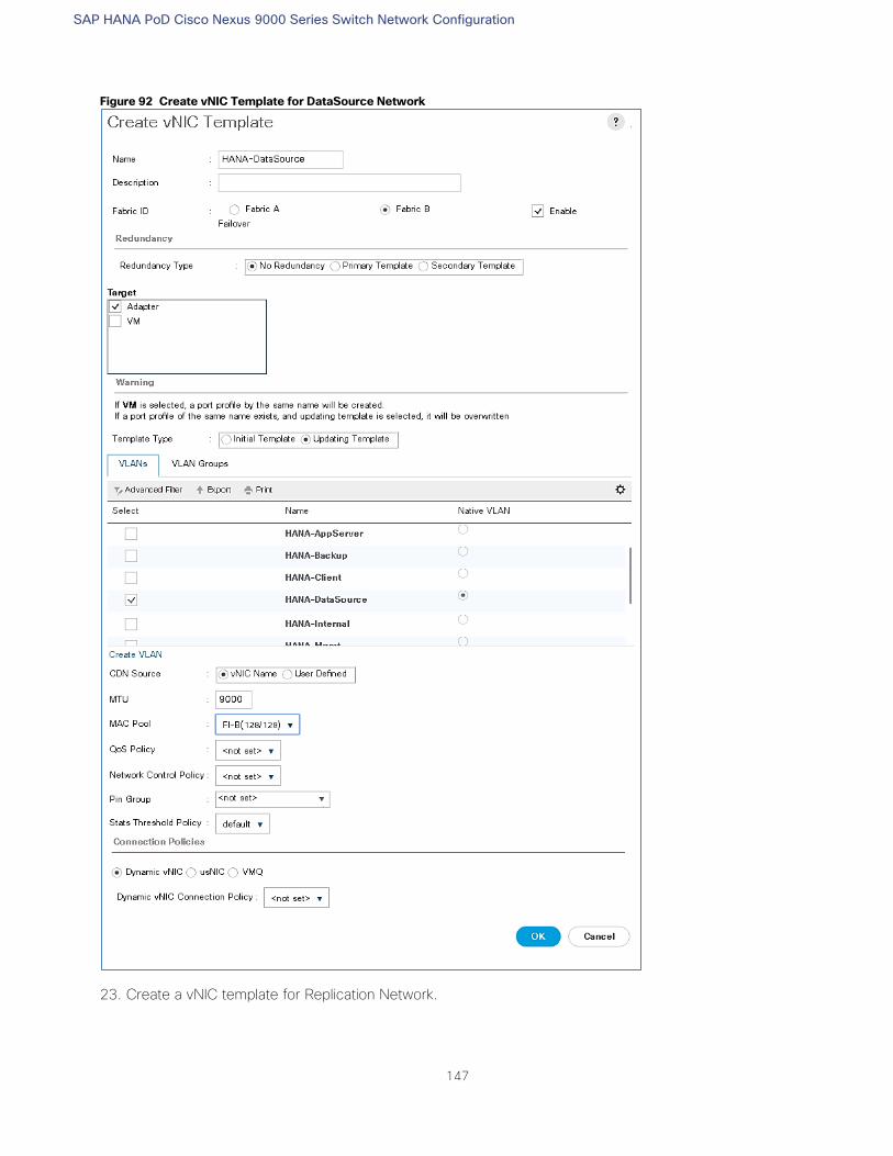
SAP HANA PoD Cisco Nexus 9000 Series Switch Network Configuration
147
Figure 92 Create vNIC Template for DataSource Network
23. Create a vNIC template for Replication Network.
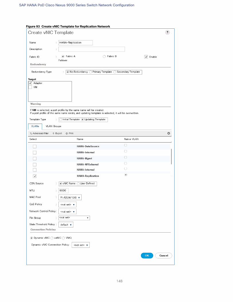
SAP HANA PoD Cisco Nexus 9000 Series Switch Network Configuration
148
Figure 93 Create vNIC Template for Replication Network
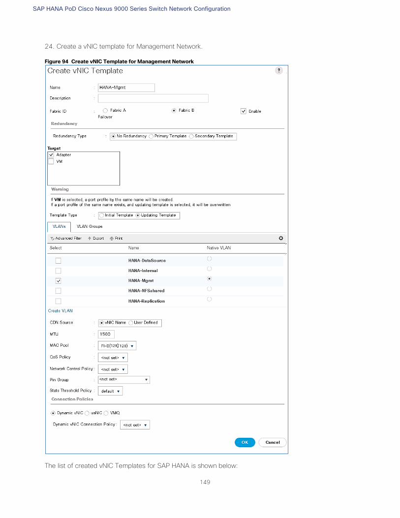
SAP HANA PoD Cisco Nexus 9000 Series Switch Network Configuration
149
24. Create a vNIC template for Management Network.
Figure 94 Create vNIC Template for Management Network
The list of created vNIC Templates for SAP HANA is shown below:
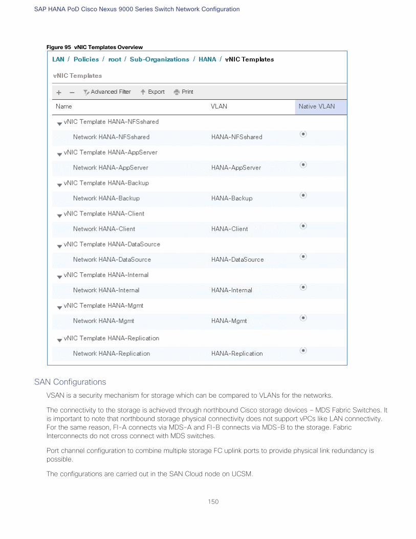
SAP HANA PoD Cisco Nexus 9000 Series Switch Network Configuration
150
Figure 95 vNIC Templates Overview
SAN Configurations
VSAN is a security mechanism for storage which can be compared to VLANs for the networks.
The connectivity to the storage is achieved through northbound Cisco storage devices – MDS Fabric Switches. It
is important to note that northbound storage physical connectivity does not support vPCs like LAN connectivity.
For the same reason, FI-A connects via MDS-A and FI-B connects via MDS-B to the storage. Fabric
Interconnects do not cross connect with MDS switches.
Port channel configuration to combine multiple storage FC uplink ports to provide physical link redundancy is
possible.
The configurations are carried out in the SAN Cloud node on UCSM.
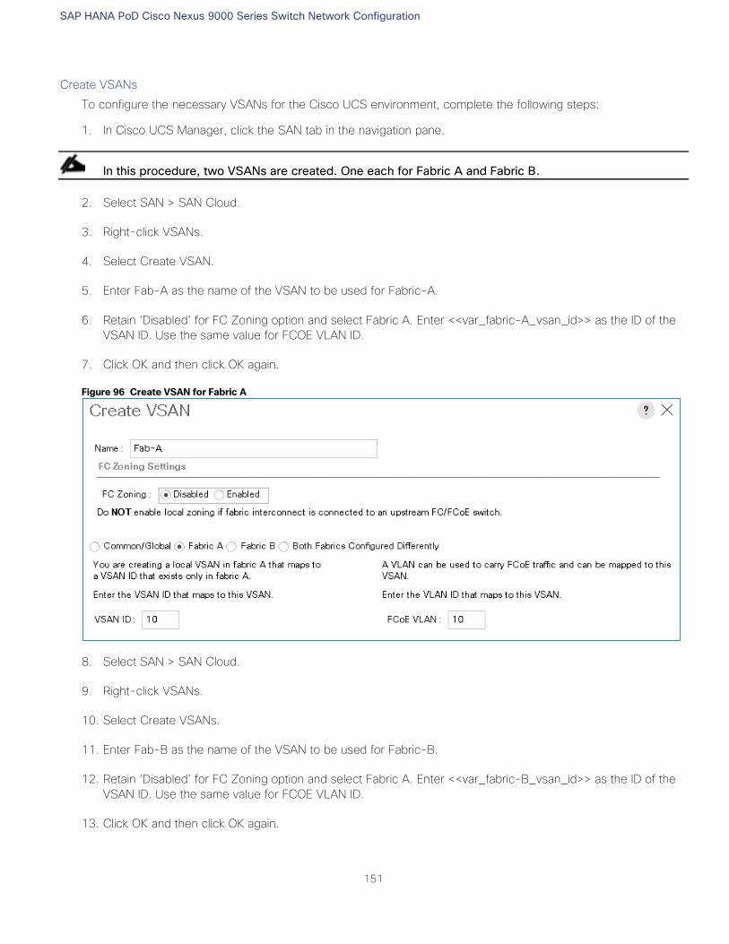
SAP HANA PoD Cisco Nexus 9000 Series Switch Network Configuration
151
Create VSANs
To configure the necessary VSANs for the Cisco UCS environment, complete the following steps:
1. In Cisco UCS Manager, click the SAN tab in the navigation pane.
In this procedure, two VSANs are created. One each for Fabric A and Fabric B.
2. Select SAN > SAN Cloud.
3. Right-click VSANs.
4. Select Create VSAN.
5. Enter Fab-A as the name of the VSAN to be used for Fabric-A.
6. Retain ‘Disabled’ for FC Zoning option and select Fabric A. Enter <<var_fabric-A_vsan_id>> as the ID of the
VSAN ID. Use the same value for FCOE VLAN ID.
7. Click OK and then click OK again.
Figure 96 Create VSAN for Fabric A
8. Select SAN > SAN Cloud.
9. Right-click VSANs.
10. Select Create VSANs.
11. Enter Fab-B as the name of the VSAN to be used for Fabric-B.
12. Retain ‘Disabled’ for FC Zoning option and select Fabric A. Enter <<var_fabric-B_vsan_id>> as the ID of the
VSAN ID. Use the same value for FCOE VLAN ID.
13. Click OK and then click OK again.
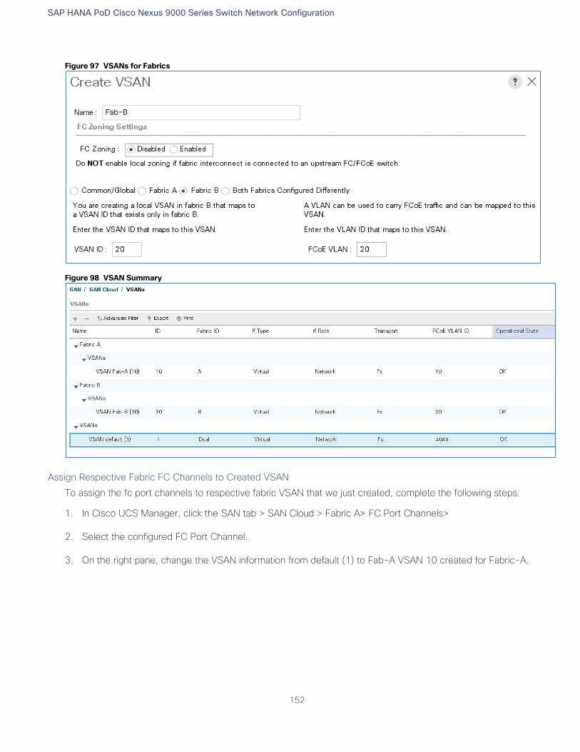
SAP HANA PoD Cisco Nexus 9000 Series Switch Network Configuration
152
Figure 97 VSANs for Fabrics
Figure 98 VSAN Summary
Assign Respective Fabric FC Channels to Created VSAN
To assign the fc port channels to respective fabric VSAN that we just created, complete the following steps:
1. In Cisco UCS Manager, click the SAN tab > SAN Cloud > Fabric A> FC Port Channels>
2. Select the configured FC Port Channel.
3. On the right pane, change the VSAN information from default (1) to Fab-A VSAN 10 created for Fabric-A.
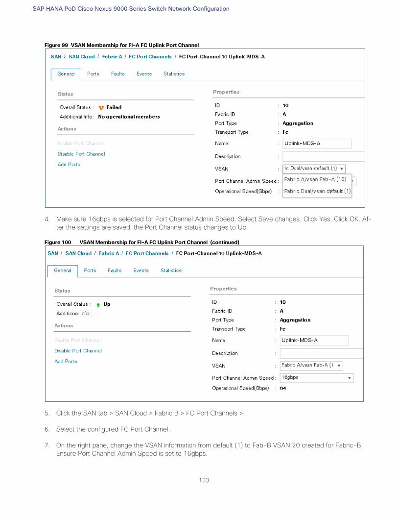
SAP HANA PoD Cisco Nexus 9000 Series Switch Network Configuration
153
Figure 99 VSAN Membership for FI-A FC Uplink Port Channel
4. Make sure 16gbps is selected for Port Channel Admin Speed. Select Save changes. Click Yes. Click OK. Af-
ter the settings are saved, the Port Channel status changes to Up.
Figure 100 VSAN Membership for FI-A FC Uplink Port Channel (continued)
5. Click the SAN tab > SAN Cloud > Fabric B > FC Port Channels >.
6. Select the configured FC Port Channel.
7. On the right pane, change the VSAN information from default (1) to Fab-B VSAN 20 created for Fabric-B.
Ensure Port Channel Admin Speed is set to 16gbps.
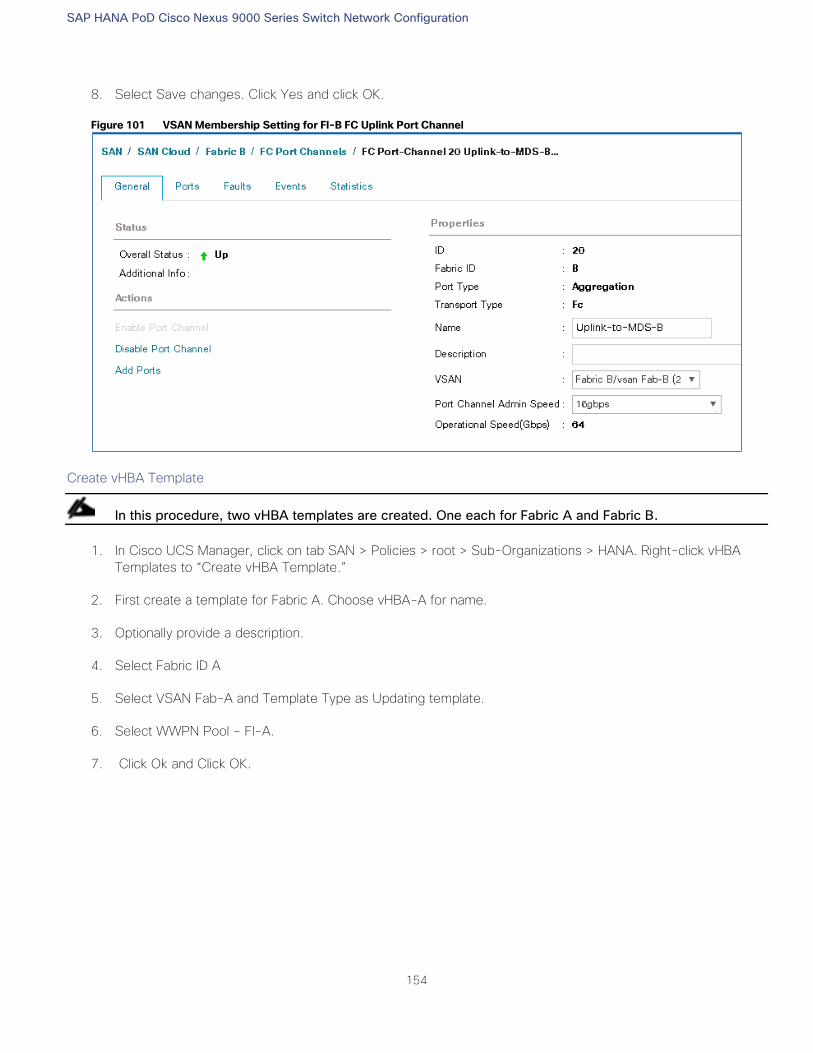
SAP HANA PoD Cisco Nexus 9000 Series Switch Network Configuration
154
8. Select Save changes. Click Yes and click OK.
Figure 101 VSAN Membership Setting for FI-B FC Uplink Port Channel
Create vHBA Template
In this procedure, two vHBA templates are created. One each for Fabric A and Fabric B.
1. In Cisco UCS Manager, click on tab SAN > Policies > root > Sub-Organizations > HANA. Right-click vHBA
Templates to “Create vHBA Template.”
2. First create a template for Fabric A. Choose vHBA-A for name.
3. Optionally provide a description.
4. Select Fabric ID A
5. Select VSAN Fab-A and Template Type as Updating template.
6. Select WWPN Pool – FI-A.
7. Click Ok and Click OK.
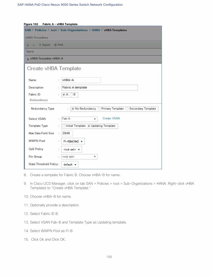
SAP HANA PoD Cisco Nexus 9000 Series Switch Network Configuration
155
Figure 102 Fabric A - vHBA Template
8. Create a template for Fabric B. Choose vHBA-B for name.
9. In Cisco UCS Manager, click on tab SAN > Policies > root > Sub-Organizations > HANA. Right-click vHBA
Templates to “Create vHBA Template.”
10. Choose vHBA-B for name.
11. Optionally provide a description.
12. Select Fabric ID B.
13. Select VSAN Fab-B and Template Type as Updating template.
14. Select WWPN Pool as FI-B.
15. Click Ok and Click OK.
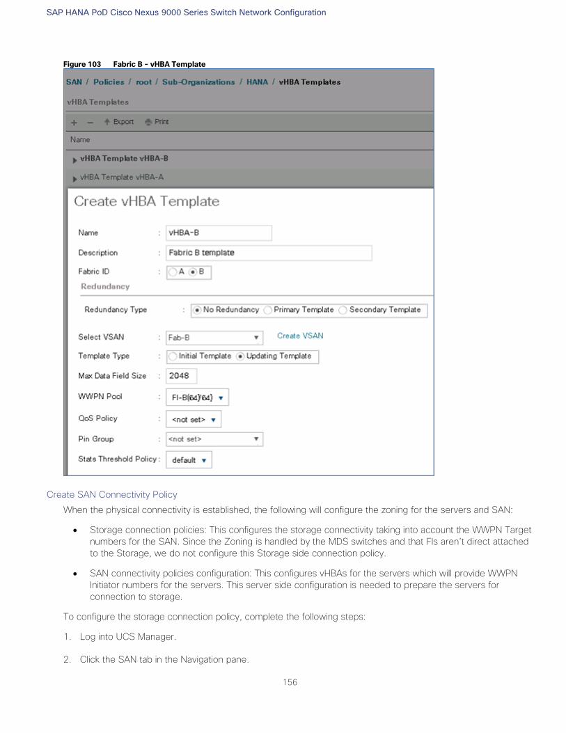
SAP HANA PoD Cisco Nexus 9000 Series Switch Network Configuration
156
Figure 103 Fabric B - vHBA Template
Create SAN Connectivity Policy
When the physical connectivity is established, the following will configure the zoning for the servers and SAN:
Storage connection policies: This configures the storage connectivity taking into account the WWPN Target
numbers for the SAN. Since the Zoning is handled by the MDS switches and that FIs aren’t direct attached
to the Storage, we do not configure this Storage side connection policy.
SAN connectivity policies configuration: This configures vHBAs for the servers which will provide WWPN
Initiator numbers for the servers. This server side configuration is needed to prepare the servers for
connection to storage.
To configure the storage connection policy, complete the following steps:
1. Log into UCS Manager.
2. Click the SAN tab in the Navigation pane.
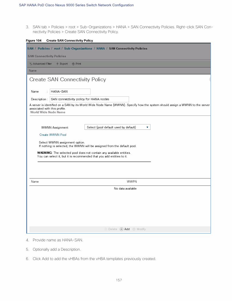
SAP HANA PoD Cisco Nexus 9000 Series Switch Network Configuration
157
3. SAN tab > Policies > root > Sub-Organizations > HANA > SAN Connectivity Policies. Right-click SAN Con-
nectivity Policies > Create SAN Connectivity Policy.
Figure 104 Create SAN Connectivity Policy
4. Provide name as HANA-SAN.
5. Optionally add a Description.
6. Click Add to add the vHBAs from the vHBA templates previously created.
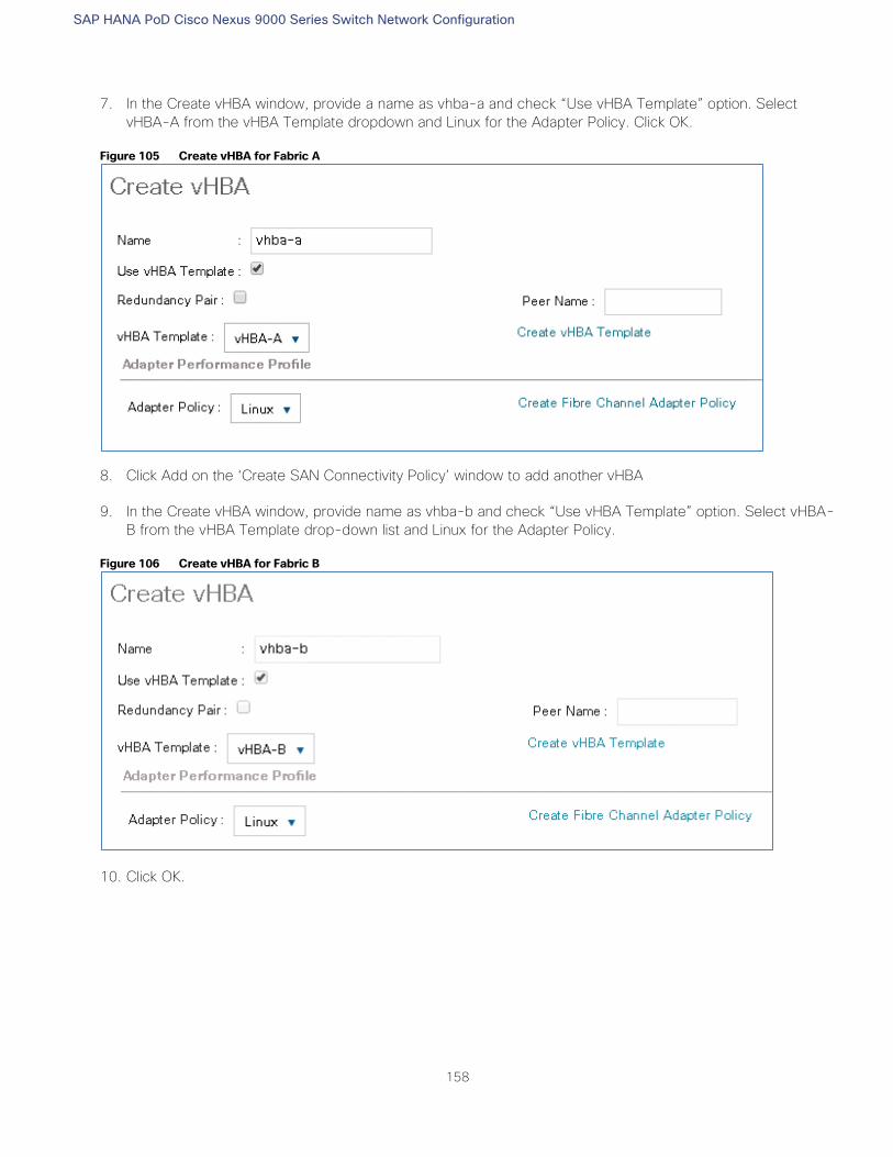
SAP HANA PoD Cisco Nexus 9000 Series Switch Network Configuration
158
7. In the Create vHBA window, provide a name as vhba-a and check “Use vHBA Template” option. Select
vHBA-A from the vHBA Template dropdown and Linux for the Adapter Policy. Click OK.
Figure 105 Create vHBA for Fabric A
8. Click Add on the ‘Create SAN Connectivity Policy’ window to add another vHBA
9. In the Create vHBA window, provide name as vhba-b and check “Use vHBA Template” option. Select vHBA-
B from the vHBA Template drop-down list and Linux for the Adapter Policy.
Figure 106 Create vHBA for Fabric B
10. Click OK.
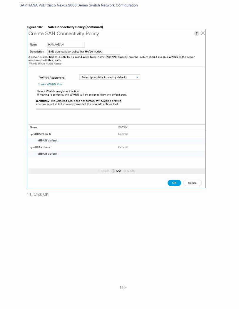
SAP HANA PoD Cisco Nexus 9000 Series Switch Network Configuration
159
Figure 107 SAN Connectivity Policy (continued)
11. Click OK.
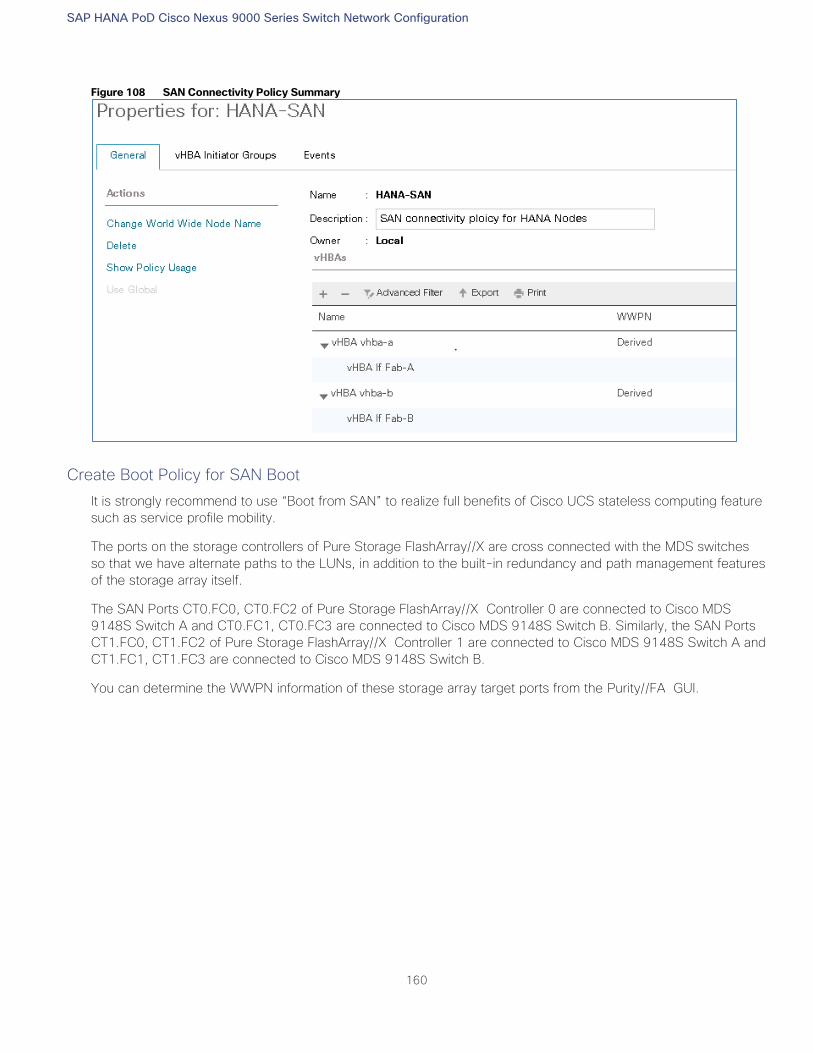
SAP HANA PoD Cisco Nexus 9000 Series Switch Network Configuration
160
Figure 108 SAN Connectivity Policy Summary
Create Boot Policy for SAN Boot
It is strongly recommend to use “Boot from SAN” to realize full benefits of Cisco UCS stateless computing feature
such as service profile mobility.
The ports on the storage controllers of Pure Storage FlashArray//X are cross connected with the MDS switches
so that we have alternate paths to the LUNs, in addition to the built-in redundancy and path management features
of the storage array itself.
The SAN Ports CT0.FC0, CT0.FC2 of Pure Storage FlashArray//X Controller 0 are connected to Cisco MDS
9148S Switch A and CT0.FC1, CT0.FC3 are connected to Cisco MDS 9148S Switch B. Similarly, the SAN Ports
CT1.FC0, CT1.FC2 of Pure Storage FlashArray//X Controller 1 are connected to Cisco MDS 9148S Switch A and
CT1.FC1, CT1.FC3 are connected to Cisco MDS 9148S Switch B.
You can determine the WWPN information of these storage array target ports from the Purity//FA GUI.
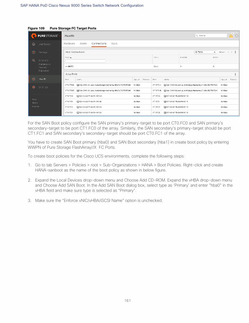
SAP HANA PoD Cisco Nexus 9000 Series Switch Network Configuration
161
Figure 109 Pure Storage FC Target Ports
For the SAN Boot policy configure the SAN primary's primary-target to be port CT0.FC0 and SAN primary's
secondary-target to be port CT1.FC0 of the array. Similarly, the SAN secondary’s primary-target should be port
CT1.FC1 and SAN secondary's secondary-target should be port CT0.FC1 of the array.
You have to create SAN Boot primary (hba0) and SAN Boot secondary (hba1) in create boot policy by entering
WWPN of Pure Storage FlashArray//X FC Ports.
To create boot policies for the Cisco UCS environments, complete the following steps:
1. Go to tab Servers > Policies > root > Sub-Organizations > HANA > Boot Policies. Right-click and create
HANA-sanboot as the name of the boot policy as shown in below figure.
2. Expand the Local Devices drop-down menu and Choose Add CD-ROM. Expand the vHBA drop-down menu
and Choose Add SAN Boot. In the Add SAN Boot dialog box, select type as ‘Primary’ and enter "hba0" in the
vHBA field and make sure type is selected as “Primary”.
3. Make sure the “Enforce vNIC/vHBA/iSCSI Name” option is unchecked.
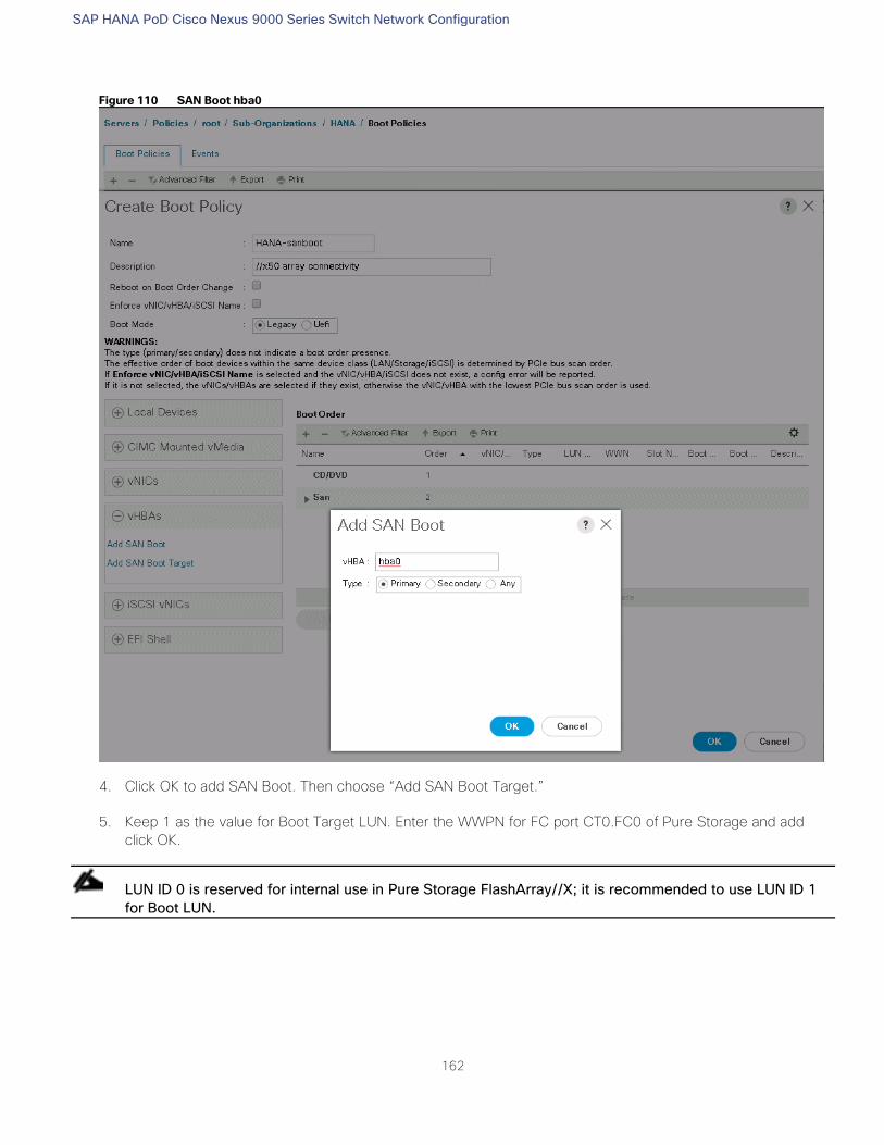
SAP HANA PoD Cisco Nexus 9000 Series Switch Network Configuration
162
Figure 110 SAN Boot hba0
4. Click OK to add SAN Boot. Then choose “Add SAN Boot Target.”
5. Keep 1 as the value for Boot Target LUN. Enter the WWPN for FC port CT0.FC0 of Pure Storage and add
click OK.
LUN ID 0 is reserved for internal use in Pure Storage FlashArray//X; it is recommended to use LUN ID 1
for Boot LUN.
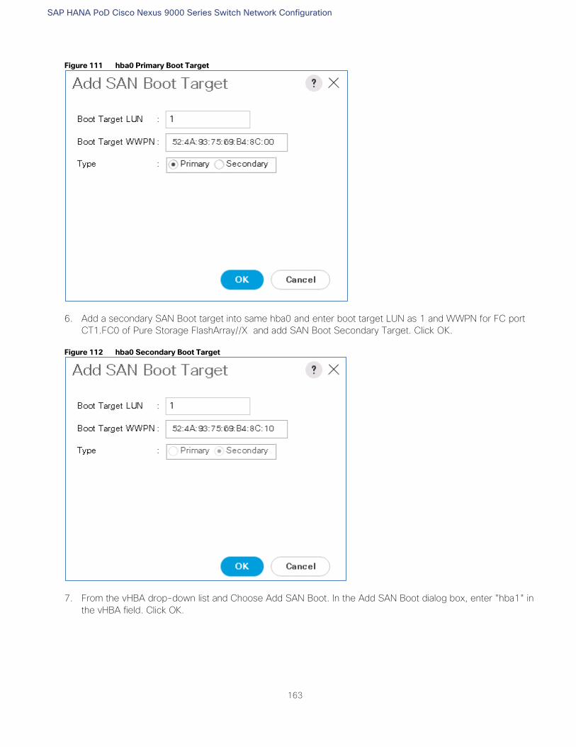
SAP HANA PoD Cisco Nexus 9000 Series Switch Network Configuration
163
Figure 111 hba0 Primary Boot Target
6. Add a secondary SAN Boot target into same hba0 and enter boot target LUN as 1 and WWPN for FC port
CT1.FC0 of Pure Storage FlashArray//X and add SAN Boot Secondary Target. Click OK.
Figure 112 hba0 Secondary Boot Target
7. From the vHBA drop-down list and Choose Add SAN Boot. In the Add SAN Boot dialog box, enter "hba1" in
the vHBA field. Click OK.
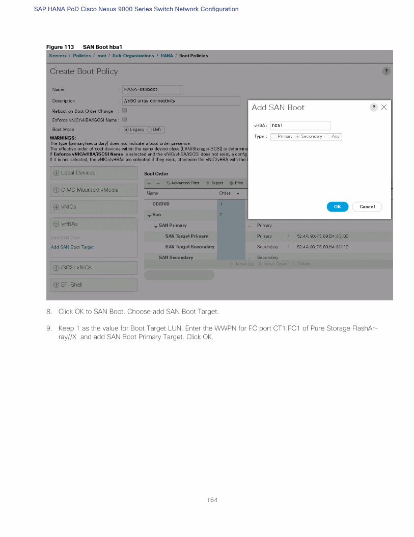
SAP HANA PoD Cisco Nexus 9000 Series Switch Network Configuration
164
Figure 113 SAN Boot hba1
8. Click OK to SAN Boot. Choose add SAN Boot Target.
9. Keep 1 as the value for Boot Target LUN. Enter the WWPN for FC port CT1.FC1 of Pure Storage FlashAr-
ray//X and add SAN Boot Primary Target. Click OK.
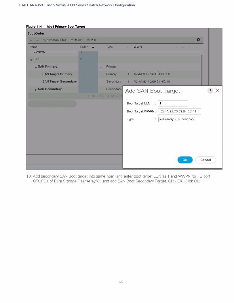
SAP HANA PoD Cisco Nexus 9000 Series Switch Network Configuration
165
Figure 114 hba1 Primary Boot Target
10. Add secondary SAN Boot target into same hba1 and enter boot target LUN as 1 and WWPN for FC port
CT0.FC1 of Pure Storage FlashArray//X and add SAN Boot Secondary Target. Click OK. Click OK.
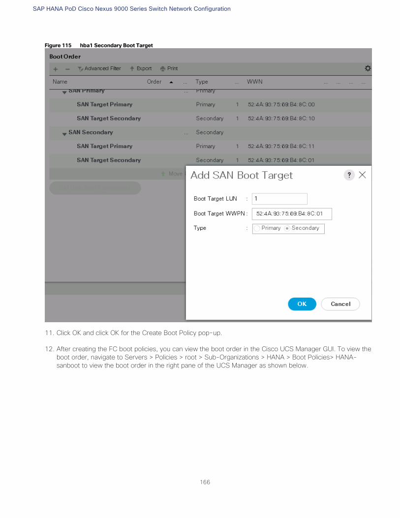
SAP HANA PoD Cisco Nexus 9000 Series Switch Network Configuration
166
Figure 115 hba1 Secondary Boot Target
11. Click OK and click OK for the Create Boot Policy pop-up.
12. After creating the FC boot policies, you can view the boot order in the Cisco UCS Manager GUI. To view the
boot order, navigate to Servers > Policies > root > Sub-Organizations > HANA > Boot Policies> HANA-
sanboot to view the boot order in the right pane of the UCS Manager as shown below.
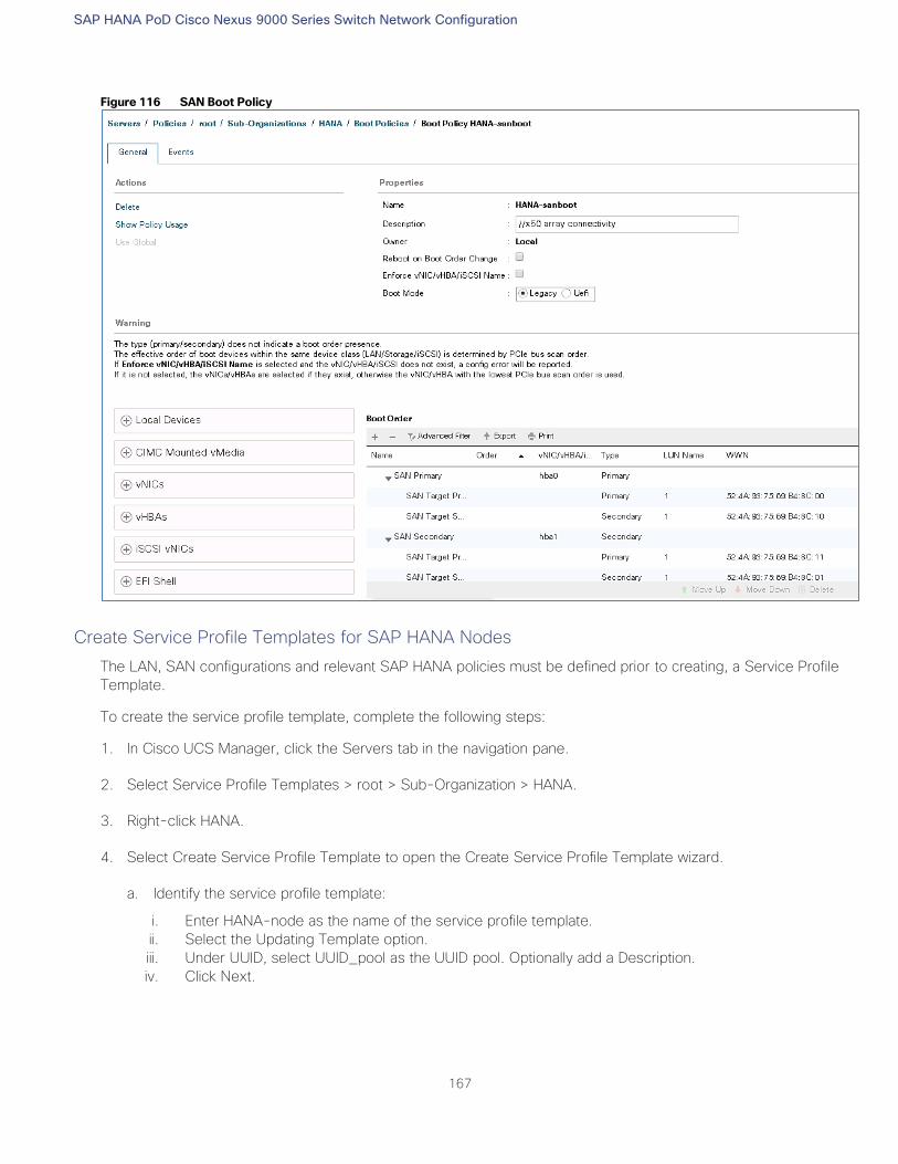
SAP HANA PoD Cisco Nexus 9000 Series Switch Network Configuration
167
Figure 116 SAN Boot Policy
Create Service Profile Templates for SAP HANA Nodes
The LAN, SAN configurations and relevant SAP HANA policies must be defined prior to creating, a Service Profile
Template.
To create the service profile template, complete the following steps:
1. In Cisco UCS Manager, click the Servers tab in the navigation pane.
2. Select Service Profile Templates > root > Sub-Organization > HANA.
3. Right-click HANA.
4. Select Create Service Profile Template to open the Create Service Profile Template wizard.
a. Identify the service profile template:
i. Enter HANA-node as the name of the service profile template.
ii. Select the Updating Template option.
iii. Under UUID, select UUID_pool as the UUID pool. Optionally add a Description.
iv. Click Next.
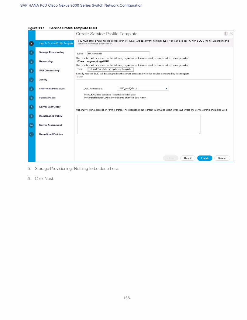
SAP HANA PoD Cisco Nexus 9000 Series Switch Network Configuration
168
Figure 117 Service Profile Template UUID
5. Storage Provisioning: Nothing to be done here.
6. Click Next.
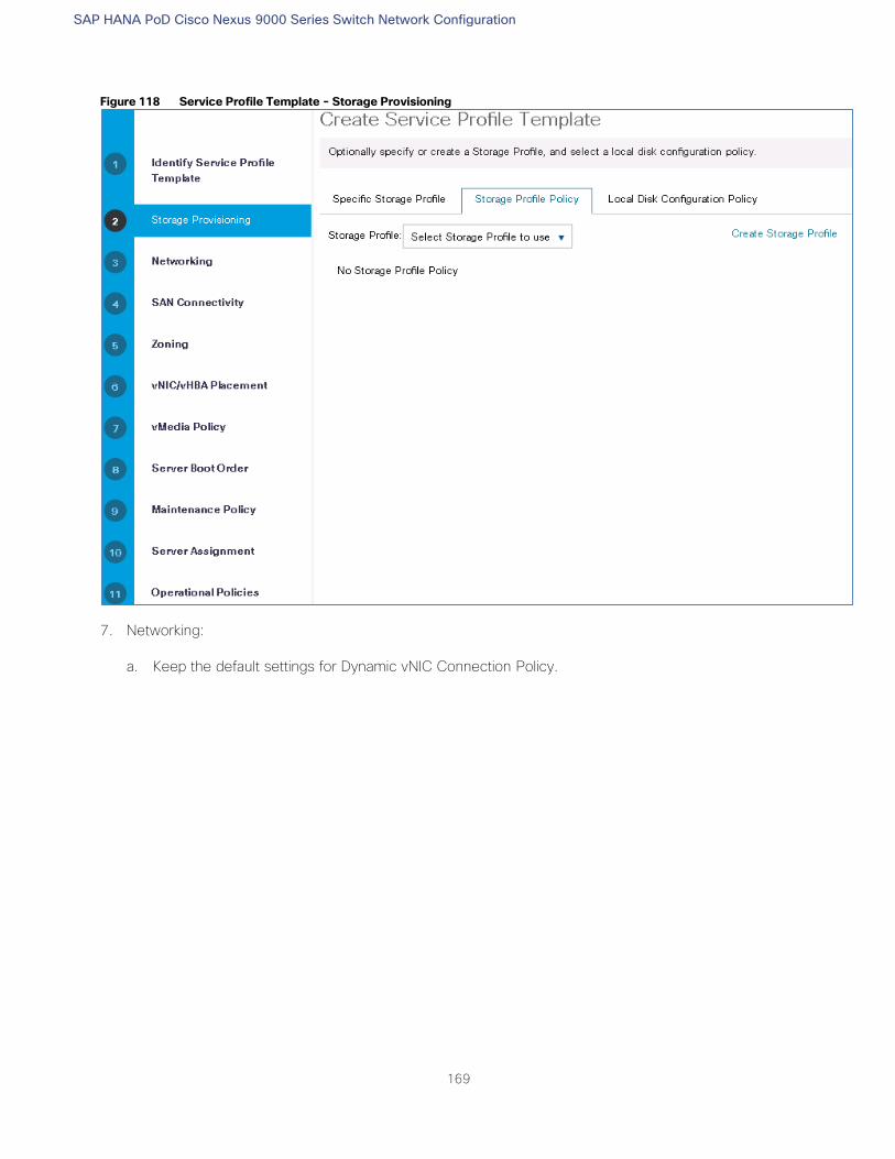
SAP HANA PoD Cisco Nexus 9000 Series Switch Network Configuration
169
Figure 118 Service Profile Template - Storage Provisioning
7. Networking:
a. Keep the default settings for Dynamic vNIC Connection Policy.
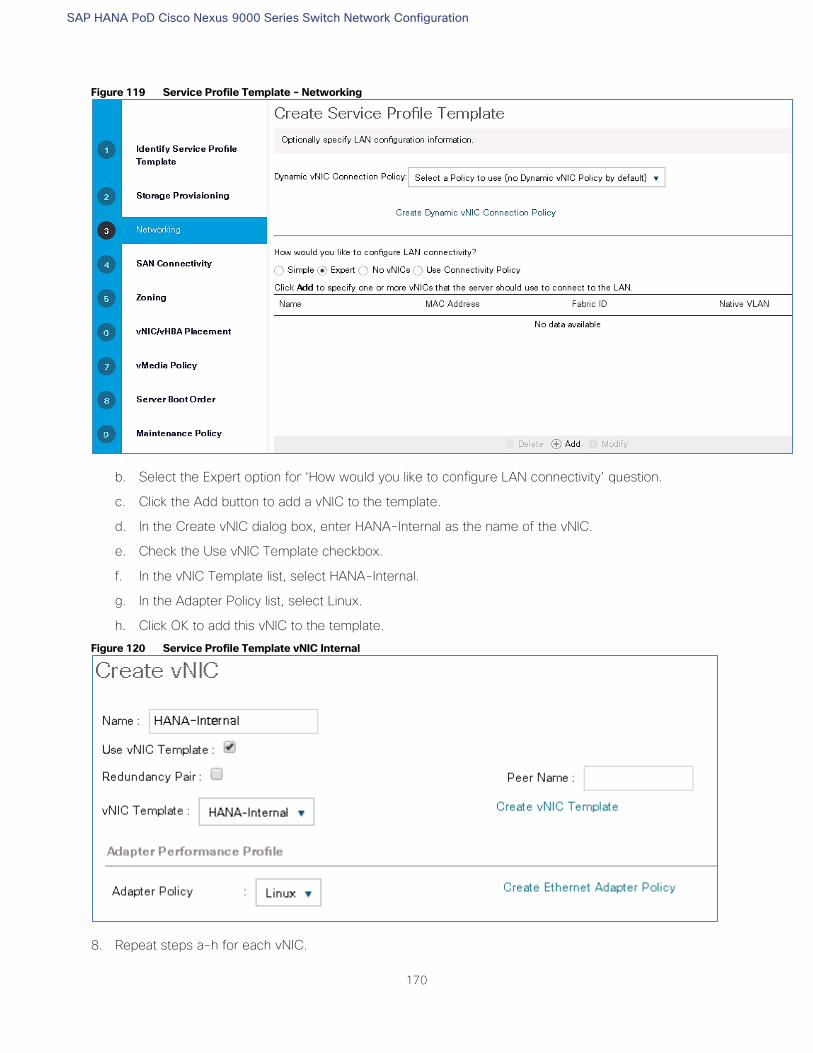
SAP HANA PoD Cisco Nexus 9000 Series Switch Network Configuration
170
Figure 119 Service Profile Template - Networking
b. Select the Expert option for ‘How would you like to configure LAN connectivity’ question.
c. Click the Add button to add a vNIC to the template.
d. In the Create vNIC dialog box, enter HANA-Internal as the name of the vNIC.
e. Check the Use vNIC Template checkbox.
f. In the vNIC Template list, select HANA-Internal.
g. In the Adapter Policy list, select Linux.
h. Click OK to add this vNIC to the template.
Figure 120 Service Profile Template vNIC Internal
8. Repeat steps a-h for each vNIC.
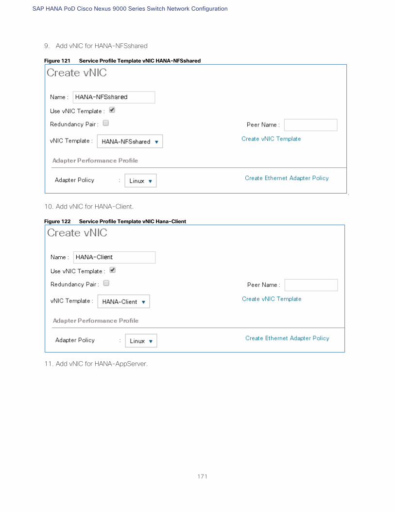
SAP HANA PoD Cisco Nexus 9000 Series Switch Network Configuration
171
9. Add vNIC for HANA-NFSshared
Figure 121 Service Profile Template vNIC HANA-NFSshared
.
10. Add vNIC for HANA-Client.
Figure 122 Service Profile Template vNIC Hana-Client
11. Add vNIC for HANA-AppServer.
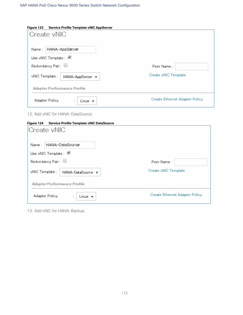
SAP HANA PoD Cisco Nexus 9000 Series Switch Network Configuration
172
Figure 123 Service Profile Template vNIC AppServer
12. Add vNIC for HANA-DataSource.
Figure 124 Service Profile Template vNIC DataSource
13. Add vNIC for HANA-Backup.
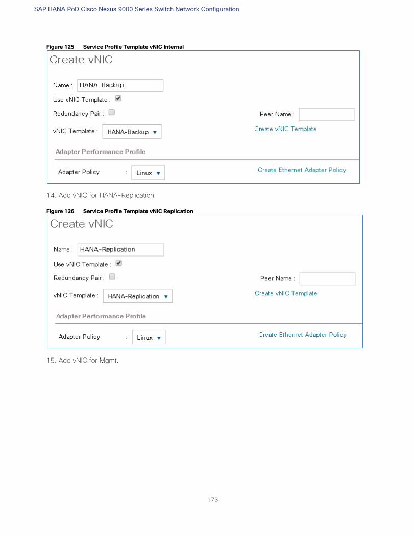
SAP HANA PoD Cisco Nexus 9000 Series Switch Network Configuration
173
Figure 125 Service Profile Template vNIC Internal
14. Add vNIC for HANA-Replication.
Figure 126 Service Profile Template vNIC Replication
15. Add vNIC for Mgmt.
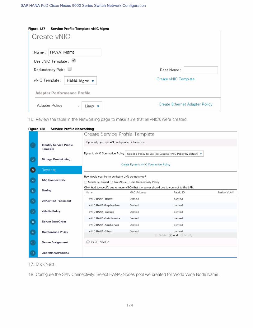
SAP HANA PoD Cisco Nexus 9000 Series Switch Network Configuration
174
Figure 127 Service Profile Template vNIC Mgmt
16. Review the table in the Networking page to make sure that all vNICs were created.
Figure 128 Service Profile Networking
17. Click Next.
18. Configure the SAN Connectivity: Select HANA-Nodes pool we created for World Wide Node Name.
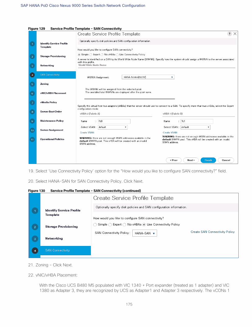
SAP HANA PoD Cisco Nexus 9000 Series Switch Network Configuration
175
Figure 129 Service Profile Template - SAN Connectivity
19. Select ‘Use Connectivity Policy’ option for the “How would you like to configure SAN connectivity?” field.
20. Select HANA-SAN for SAN Connectivity Policy. Click Next.
Figure 130 Service Profile Template - SAN Connectivity (continued)
21. Zoning – Click Next.
22. vNIC/vHBA Placement:
With the Cisco UCS B480 M5 populated with VIC 1340 + Port expander (treated as 1 adapter) and VIC
1380 as Adapter 3, they are recognized by UCS as Adapter1 and Adapter 3 respectively. The vCONs 1
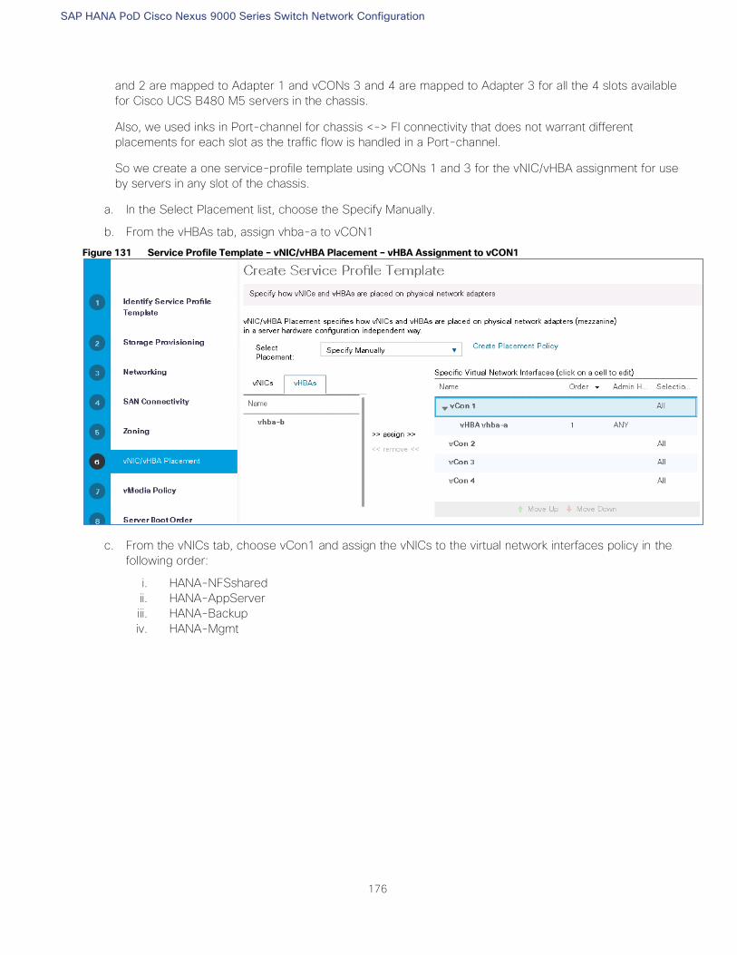
SAP HANA PoD Cisco Nexus 9000 Series Switch Network Configuration
176
and 2 are mapped to Adapter 1 and vCONs 3 and 4 are mapped to Adapter 3 for all the 4 slots available
for Cisco UCS B480 M5 servers in the chassis.
Also, we used inks in Port-channel for chassis <-> FI connectivity that does not warrant different
placements for each slot as the traffic flow is handled in a Port-channel.
So we create a one service-profile template using vCONs 1 and 3 for the vNIC/vHBA assignment for use
by servers in any slot of the chassis.
a. In the Select Placement list, choose the Specify Manually.
b. From the vHBAs tab, assign vhba-a to vCON1
Figure 131 Service Profile Template – vNIC/vHBA Placement – vHBA Assignment to vCON1
c. From the vNICs tab, choose vCon1 and assign the vNICs to the virtual network interfaces policy in the
following order:
i. HANA-NFSshared
ii. HANA-AppServer
iii. HANA-Backup
iv. HANA-Mgmt
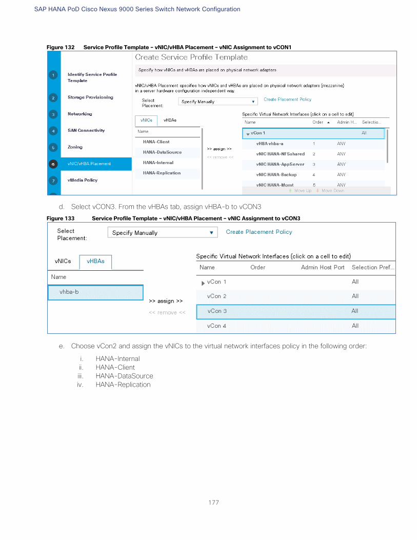
SAP HANA PoD Cisco Nexus 9000 Series Switch Network Configuration
177
Figure 132 Service Profile Template – vNIC/vHBA Placement – vNIC Assignment to vCON1
d. Select vCON3. From the vHBAs tab, assign vHBA-b to vCON3
Figure 133 Service Profile Template – vNIC/vHBA Placement – vNIC Assignment to vCON3
e. Choose vCon2 and assign the vNICs to the virtual network interfaces policy in the following order:
i. HANA-Internal
ii. HANA-Client
iii. HANA-DataSource
iv. HANA-Replication
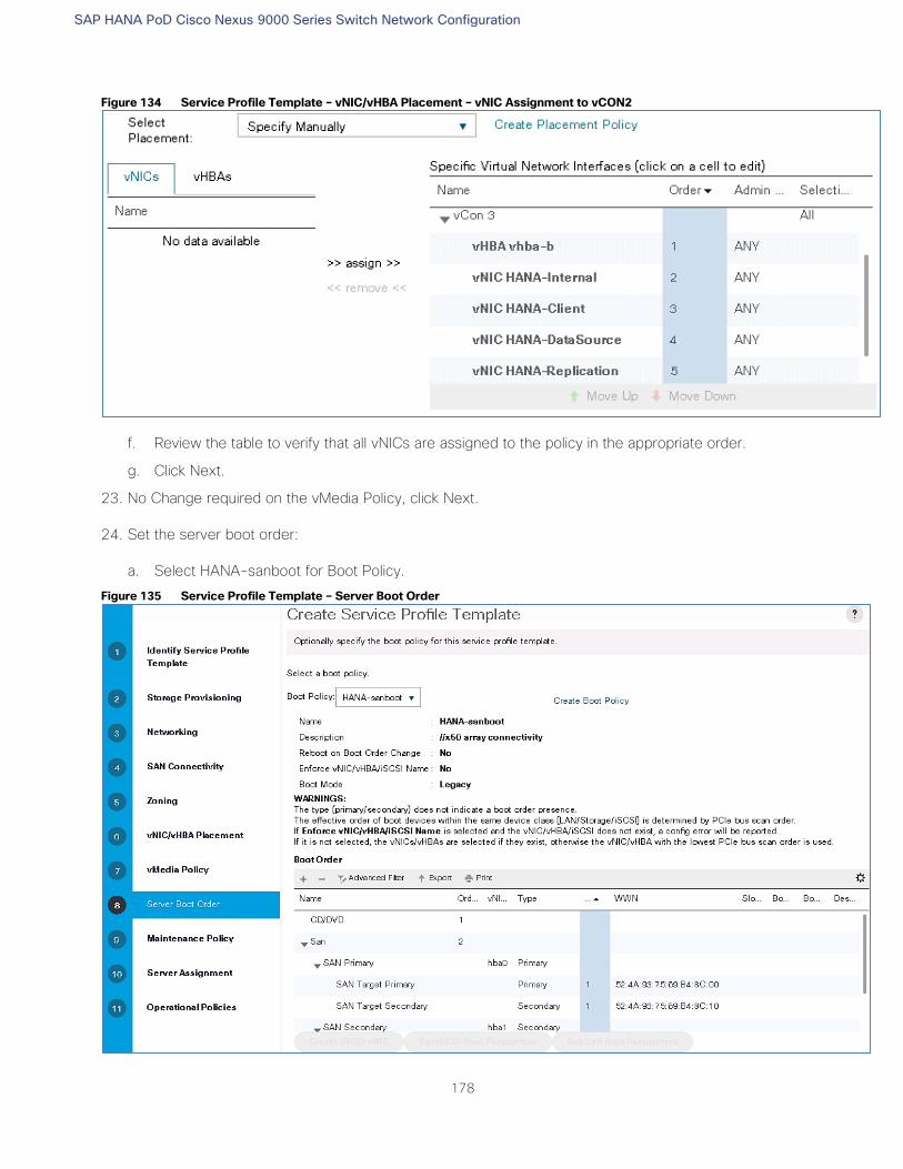
SAP HANA PoD Cisco Nexus 9000 Series Switch Network Configuration
178
Figure 134 Service Profile Template – vNIC/vHBA Placement – vNIC Assignment to vCON2
f. Review the table to verify that all vNICs are assigned to the policy in the appropriate order.
g. Click Next.
23. No Change required on the vMedia Policy, click Next.
24. Set the server boot order:
a. Select HANA-sanboot for Boot Policy.
Figure 135 Service Profile Template – Server Boot Order
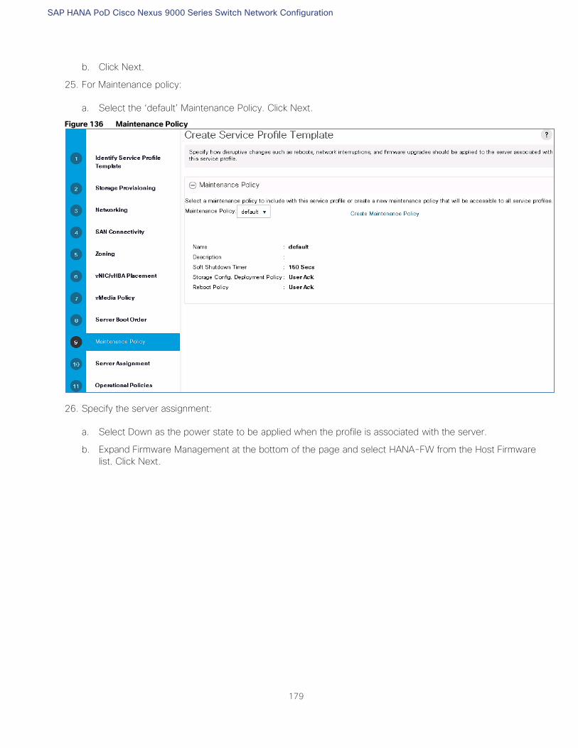
SAP HANA PoD Cisco Nexus 9000 Series Switch Network Configuration
179
b. Click Next.
25. For Maintenance policy:
a. Select the ‘default’ Maintenance Policy. Click Next.
Figure 136 Maintenance Policy
26. Specify the server assignment:
a. Select Down as the power state to be applied when the profile is associated with the server.
b. Expand Firmware Management at the bottom of the page and select HANA-FW from the Host Firmware
list. Click Next.
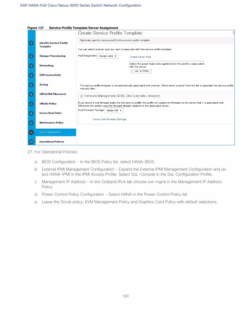
SAP HANA PoD Cisco Nexus 9000 Series Switch Network Configuration
180
Figure 137 Service Profile Template Server Assignment
27. For Operational Policies:
a. BIOS Configuration - In the BIOS Policy list, select HANA-BIOS.
b. External IPMI Management Configuration - Expand the External IPMI Management Configuration and se-
lect HANA-IPMI in the IPMI Access Profile. Select SoL-Console in the SoL Configuration Profile.
c. Management IP Address - In the Outband IPv4 tab choose ext-mgmt in the Management IP Address
Policy.
d. Power Control Policy Configuration - Select HANA in the Power Control Policy list.
e. Leave the Scrub policy, KVM Management Policy and Graphics Card Policy with default selections.
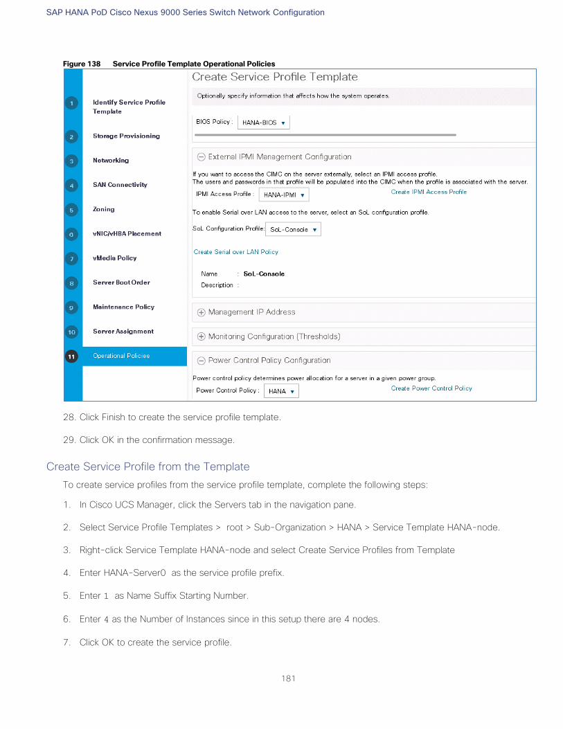
SAP HANA PoD Cisco Nexus 9000 Series Switch Network Configuration
181
Figure 138 Service Profile Template Operational Policies
28. Click Finish to create the service profile template.
29. Click OK in the confirmation message.
Create Service Profile from the Template
To create service profiles from the service profile template, complete the following steps:
1. In Cisco UCS Manager, click the Servers tab in the navigation pane.
2. Select Service Profile Templates > root > Sub-Organization > HANA > Service Template HANA-node.
3. Right-click Service Template HANA-node and select Create Service Profiles from Template
4. Enter HANA-Server0 as the service profile prefix.
5. Enter 1 as Name Suffix Starting Number.
6. Enter 4 as the Number of Instances since in this setup there are 4 nodes.
7. Click OK to create the service profile.
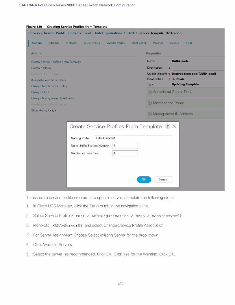
SAP HANA PoD Cisco Nexus 9000 Series Switch Network Configuration
182
Figure 139 Creating Service Profiles from Template
To associate service profile created for a specific server, complete the following steps:
1. In Cisco UCS Manager, click the Servers tab in the navigation pane.
2. Select Service Profile > root > Sub-Organization > HANA > HANA-Server01.
3. Right-click HANA-Server01 and select Change Service Profile Association.
4. For Server Assignment Choose Select existing Server for the drop-down.
5. Click Available Servers.
6. Select the server, as recommended. Click OK. Click Yes for the Warning. Click OK.
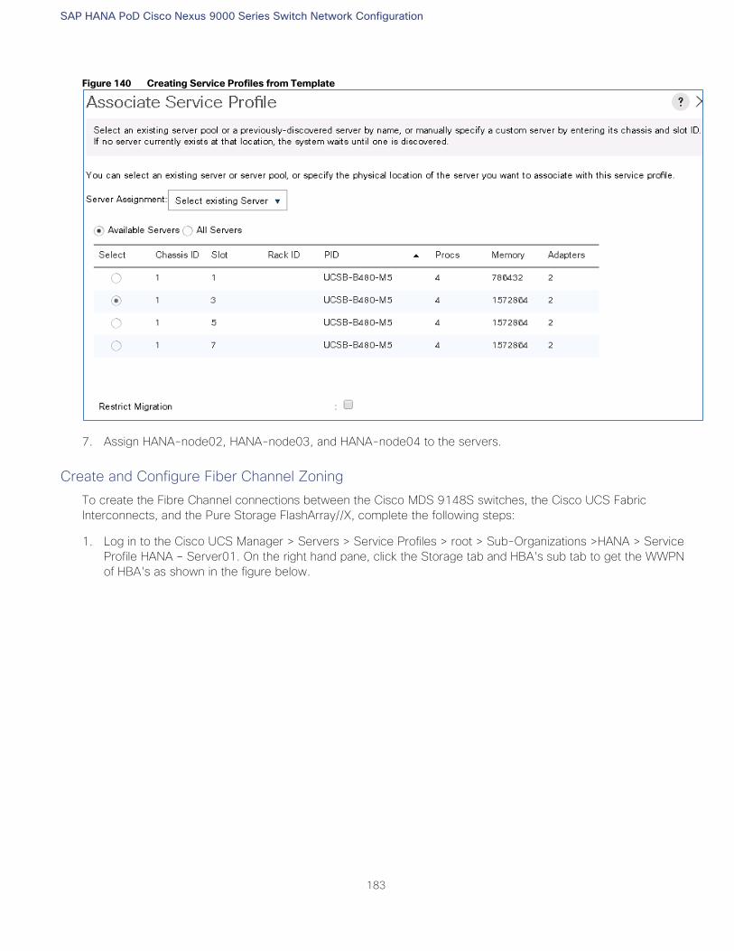
SAP HANA PoD Cisco Nexus 9000 Series Switch Network Configuration
183
Figure 140 Creating Service Profiles from Template
7. Assign HANA-node02, HANA-node03, and HANA-node04 to the servers.
Create and Configure Fiber Channel Zoning
To create the Fibre Channel connections between the Cisco MDS 9148S switches, the Cisco UCS Fabric
Interconnects, and the Pure Storage FlashArray//X, complete the following steps:
1. Log in to the Cisco UCS Manager > Servers > Service Profiles > root > Sub-Organizations >HANA > Service
Profile HANA – Server01. On the right hand pane, click the Storage tab and HBA's sub tab to get the WWPN
of HBA's as shown in the figure below.
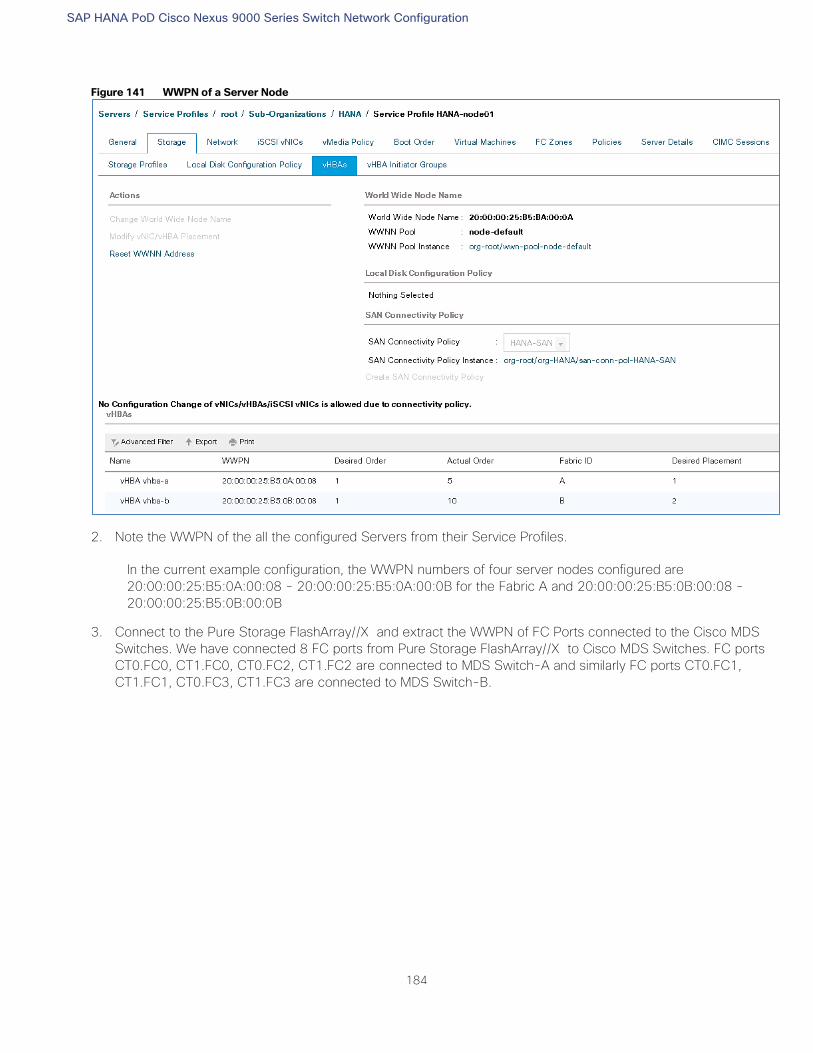
SAP HANA PoD Cisco Nexus 9000 Series Switch Network Configuration
184
Figure 141 WWPN of a Server Node
2. Note the WWPN of the all the configured Servers from their Service Profiles.
In the current example configuration, the WWPN numbers of four server nodes configured are
20:00:00:25:B5:0A:00:08 - 20:00:00:25:B5:0A:00:0B for the Fabric A and 20:00:00:25:B5:0B:00:08 -
20:00:00:25:B5:0B:00:0B
3. Connect to the Pure Storage FlashArray//X and extract the WWPN of FC Ports connected to the Cisco MDS
Switches. We have connected 8 FC ports from Pure Storage FlashArray//X to Cisco MDS Switches. FC ports
CT0.FC0, CT1.FC0, CT0.FC2, CT1.FC2 are connected to MDS Switch-A and similarly FC ports CT0.FC1,
CT1.FC1, CT0.FC3, CT1.FC3 are connected to MDS Switch-B.
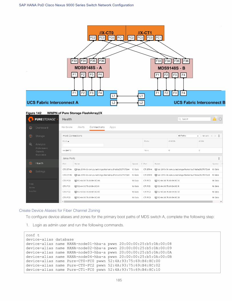
SAP HANA PoD Cisco Nexus 9000 Series Switch Network Configuration
185
Figure 142 WWPN of Pure Storage FlashArray//X
Create Device Aliases for Fiber Channel Zoning
To configure device aliases and zones for the primary boot paths of MDS switch A, complete the following step:
1. Login as admin user and run the following commands.
conf t
device-alias database
device-alias name HANA-node01-hba-a pwwn 20:00:00:25:b5:0A:00:08
device-alias name HANA-node02-hba-a pwwn 20:00:00:25:b5:0A:00:09
device-alias name HANA-node03-hba-a pwwn 20:00:00:25:b5:0A:00:0A
device-alias name HANA-node04-hba-a pwwn 20:00:00:25:b5:0A:00:0B
device-alias name Pure-CT0-FC0 pwwn 52:4A:93:75:69:B4:8C:00
device-alias name Pure-CT0-FC2 pwwn 52:4A:93:75:69:B4:8C:02
device-alias name Pure-CT1-FC0 pwwn 52:4A:93:75:69:B4:8C:10
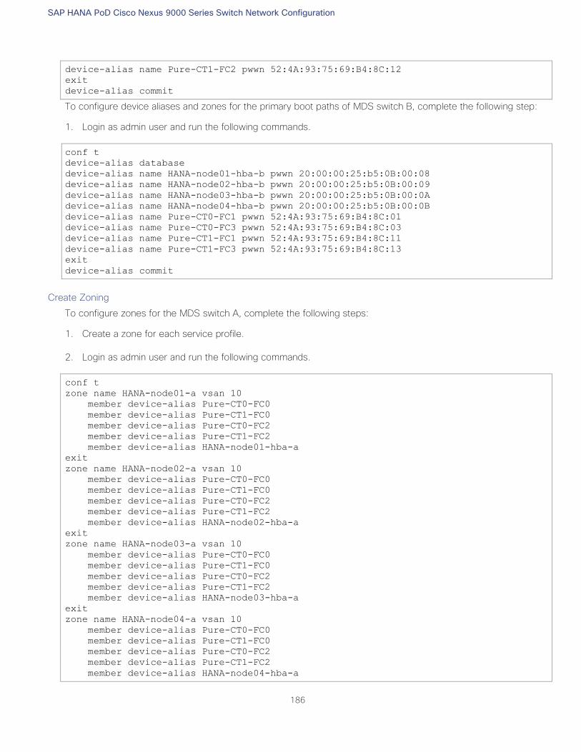
SAP HANA PoD Cisco Nexus 9000 Series Switch Network Configuration
186
device-alias name Pure-CT1-FC2 pwwn 52:4A:93:75:69:B4:8C:12
exit
device-alias commit
To configure device aliases and zones for the primary boot paths of MDS switch B, complete the following step:
1. Login as admin user and run the following commands.
conf t
device-alias database
device-alias name HANA-node01-hba-b pwwn 20:00:00:25:b5:0B:00:08
device-alias name HANA-node02-hba-b pwwn 20:00:00:25:b5:0B:00:09
device-alias name HANA-node03-hba-b pwwn 20:00:00:25:b5:0B:00:0A
device-alias name HANA-node04-hba-b pwwn 20:00:00:25:b5:0B:00:0B
device-alias name Pure-CT0-FC1 pwwn 52:4A:93:75:69:B4:8C:01
device-alias name Pure-CT0-FC3 pwwn 52:4A:93:75:69:B4:8C:03
device-alias name Pure-CT1-FC1 pwwn 52:4A:93:75:69:B4:8C:11
device-alias name Pure-CT1-FC3 pwwn 52:4A:93:75:69:B4:8C:13
exit
device-alias commit
Create Zoning
To configure zones for the MDS switch A, complete the following steps:
1. Create a zone for each service profile.
2. Login as admin user and run the following commands.
conf t
zone name HANA-node01-a vsan 10
member device-alias Pure-CT0-FC0
member device-alias Pure-CT1-FC0
member device-alias Pure-CT0-FC2
member device-alias Pure-CT1-FC2
member device-alias HANA-node01-hba-a
exit
zone name HANA-node02-a vsan 10
member device-alias Pure-CT0-FC0
member device-alias Pure-CT1-FC0
member device-alias Pure-CT0-FC2
member device-alias Pure-CT1-FC2
member device-alias HANA-node02-hba-a
exit
zone name HANA-node03-a vsan 10
member device-alias Pure-CT0-FC0
member device-alias Pure-CT1-FC0
member device-alias Pure-CT0-FC2
member device-alias Pure-CT1-FC2
member device-alias HANA-node03-hba-a
exit
zone name HANA-node04-a vsan 10
member device-alias Pure-CT0-FC0
member device-alias Pure-CT1-FC0
member device-alias Pure-CT0-FC2
member device-alias Pure-CT1-FC2
member device-alias HANA-node04-hba-a
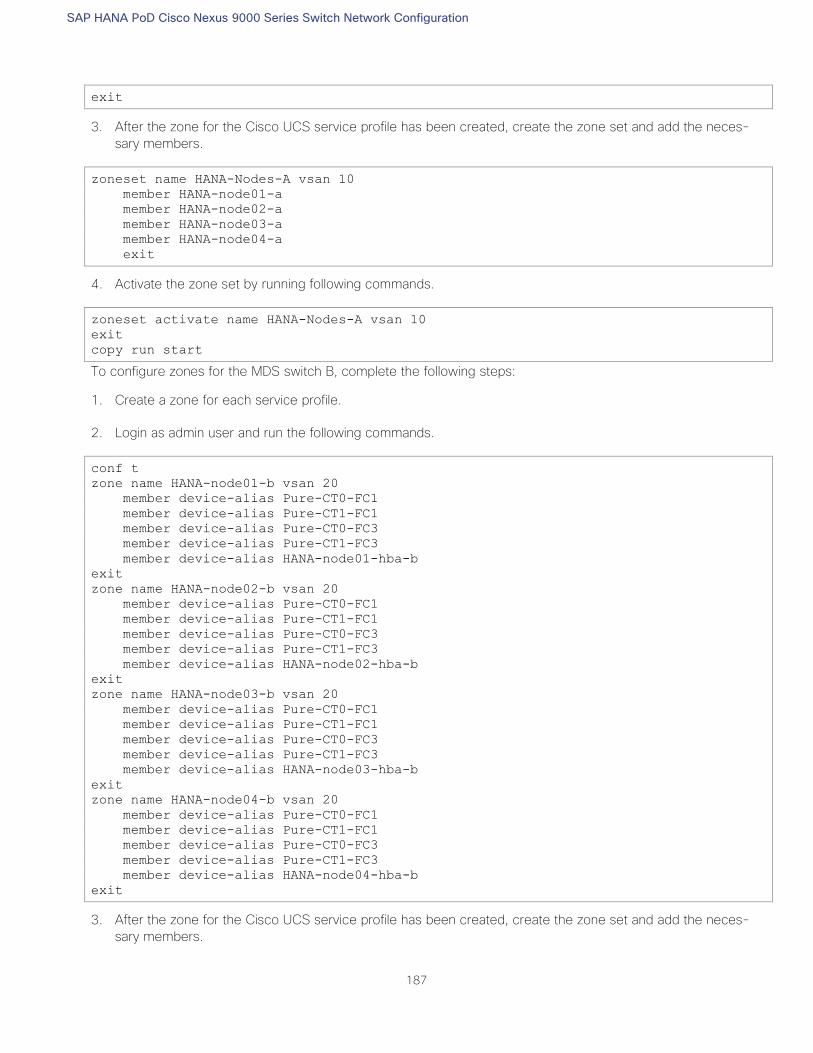
SAP HANA PoD Cisco Nexus 9000 Series Switch Network Configuration
187
exit
3. After the zone for the Cisco UCS service profile has been created, create the zone set and add the neces-
sary members.
zoneset name HANA-Nodes-A vsan 10
member HANA-node01-a
member HANA-node02-a
member HANA-node03-a
member HANA-node04-a
exit
4. Activate the zone set by running following commands.
zoneset activate name HANA-Nodes-A vsan 10
exit
copy run start
To configure zones for the MDS switch B, complete the following steps:
1. Create a zone for each service profile.
2. Login as admin user and run the following commands.
conf t
zone name HANA-node01-b vsan 20
member device-alias Pure-CT0-FC1
member device-alias Pure-CT1-FC1
member device-alias Pure-CT0-FC3
member device-alias Pure-CT1-FC3
member device-alias HANA-node01-hba-b
exit
zone name HANA-node02-b vsan 20
member device-alias Pure-CT0-FC1
member device-alias Pure-CT1-FC1
member device-alias Pure-CT0-FC3
member device-alias Pure-CT1-FC3
member device-alias HANA-node02-hba-b
exit
zone name HANA-node03-b vsan 20
member device-alias Pure-CT0-FC1
member device-alias Pure-CT1-FC1
member device-alias Pure-CT0-FC3
member device-alias Pure-CT1-FC3
member device-alias HANA-node03-hba-b
exit
zone name HANA-node04-b vsan 20
member device-alias Pure-CT0-FC1
member device-alias Pure-CT1-FC1
member device-alias Pure-CT0-FC3
member device-alias Pure-CT1-FC3
member device-alias HANA-node04-hba-b
exit
3. After the zone for the Cisco UCS service profile has been created, create the zone set and add the neces-
sary members.
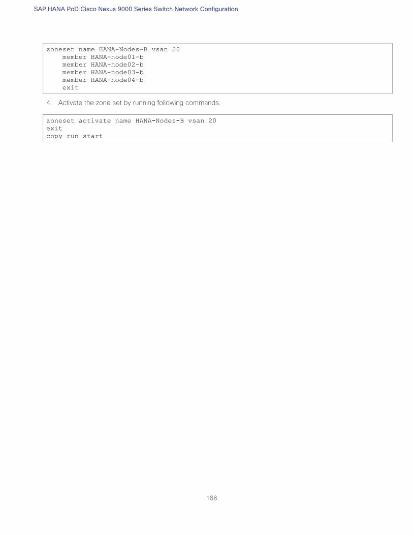
SAP HANA PoD Cisco Nexus 9000 Series Switch Network Configuration
188
zoneset name HANA-Nodes-B vsan 20
member HANA-node01-b
member HANA-node02-b
member HANA-node03-b
member HANA-node04-b
exit
4. Activate the zone set by running following commands.
zoneset activate name HANA-Nodes-B vsan 20
exit
copy run start
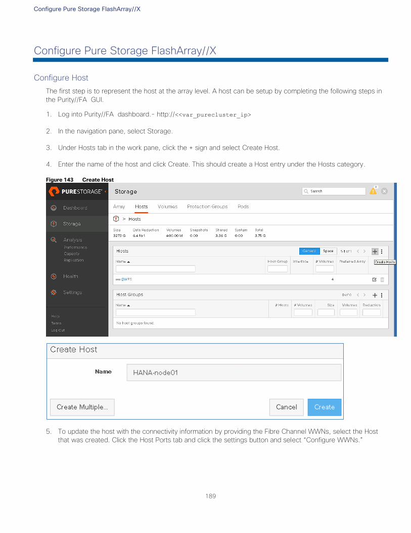
Configure Pure Storage FlashArray//X
189
Configure Pure Storage FlashArray//X
Configure Host
The first step is to represent the host at the array level. A host can be setup by completing the following steps in
the Purity//FA GUI.
1. Log into Purity//FA dashboard.- http://<<var_purecluster_ip>
2. In the navigation pane, select Storage.
3. Under Hosts tab in the work pane, click the + sign and select Create Host.
4. Enter the name of the host and click Create. This should create a Host entry under the Hosts category.
Figure 143 Create Host
5. To update the host with the connectivity information by providing the Fibre Channel WWNs, select the Host
that was created. Click the Host Ports tab and click the settings button and select “Configure WWNs.”
Configure Pure Storage FlashArray//X
190
Figure 144 Configure Host Port WWNs
6. Select the vhba-a and vhba-b pwwns from the listed WWNs for the host in question, by verifying this infor-
mation from UCSM.
Figure 145 Assign Fabric –A PWWN to Host
7. Click Add.
Configure Pure Storage FlashArray//X
191
Figure 146 Host WWNs Ports Summary
8. Follow steps 1-7 to configure the Hosts – HANA-node02, HANA-node03 and HANA-node04, mapping their
respective vHBAs Port WWNs.
Configure Pure Storage FlashArray//X
192
Figure 147 Host Summary
Configure Volume
To configure a volume, complete the following steps:
1. Go to the Storage tab on the navigation pane. Select the Volumes tab in the work pane and click the + sign to
create volumes.
Figure 148 Create Boot Volume
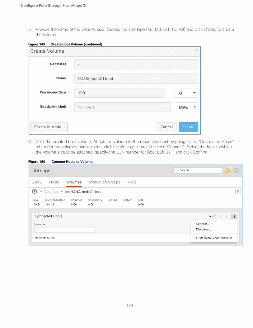
Configure Pure Storage FlashArray//X
193
2. Provide the name of the volume, size, choose the size type (KB, MB, GB, TB, PB) and click Create to create
the volume.
Figure 149 Create Boot Volume (continued)
3. Click the created boot volume. Attach the volume to the respective host by going to the “Connected Hosts”
tab under the volume context menu, click the Settings icon and select “Connect”. Select the host to which
the volume should be attached, specify the LUN number for Boot LUN as 1 and click Confirm.
Figure 150 Connect Hosts to Volume
Configure Pure Storage FlashArray//X
194
Figure 151 Connect Hosts to Volume (continued)
This completes the connectivity of the volume to the server node. We have created one boot volume (HANA-
node01-boot) of 100GB and assigned this volume to the first HANA node “HANA-node01”. Install the OS and
perform all prerequisites to be able to install SAP HANA on this LUN.
When there is a reference configuration of the OS, complaint with SAP Note recommendations, you could create
clones of this volume for use with other hosts in the cluster. For example, HANA-node02-boot, HANA-node03-
boot and HANA-node04-boot for use with HANA-node02, HANA-node03 and HANA-node04.
To create a volume clone, complete the following steps:
1. Select the volume to be used as clone source under Storage> Volumes.
2. In the right pane, use the menu bar to on the right to select ‘Copy volume’ option. Provide a name in the
Copy Volume pop-up and click Create.
Configure Pure Storage FlashArray//X
195
Figure 152 Select Volume for Clone
Figure 153 Copy Volume
3. The clone generated volume can now be associated with the host. In the Connect Hosts pane, select the vol-
ume by clicking the > and right-click the menu bar to select Connect Host.
Configure Pure Storage FlashArray//X
196
Figure 154 Connect Hosts to Volume
4. In the left pane select the host to connect and select 1 for LUN ID and click Confirm.
Figure 155 Connect Hosts to Volume (continued)
5. Post OS installation and configuration of the HANA-node01 system, prepare clones of HANA-node01-boot
volume as HANA-node02-boot, HANA-node03-boot, and HANA-node04-boot for use with hosts HANA-
nodes02, HANA-node03 and HANA-node04.
Configure Pure Storage FlashArray//X
197
Configure NFS share for /hana/shared
With Pure's Purity//FA 4.10.9 or higher, it is possible to have VM instance of Windows Server 2016 running in
each of the controllers which will then form a Windows Failover Cluster. File Servers will then be created within
the cluster to serve NFS shares.
Each WFS VM is installed on its own separate boot volume. For Windows clustering purposes, a default quorum
witness volume is exported to both WFS VMs. Lastly, a default data volume is also created where file services
data will reside. Subsequent data volumes can be created if additional capacity is required. Data volumes are also
exported to both WFS VMs to ensure persistent data across WFS VM failovers.
For more information about the best practices for WFS on Purity RUN refer to the Support page.
Requirements for the WFS configuration:
The FlashArray must have two 10G iSCSI ports on each controller for cluster and file services client traffic
— iSCSI ports eth4 and eth5 on controllers 0 and 1 are used for the same
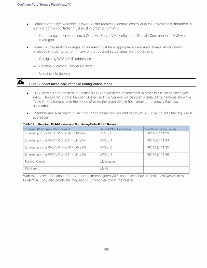
Configure Pure Storage FlashArray//X
198
Domain Controller: Microsoft Failover Cluster requires a domain controller in the environment, therefore, a
working domain controller must exist in order to run WFS.
— In the validation environment a Windows Server VM configured a Domain Controller with DNS was
leveraged.
Domain Administrator Privileges: Customers must have appropriately elevated Domain Administrator
privileges in order to perform many of the required setup steps like the following:
— Configuring WFS VM IP addresses
— Creating Microsoft Failover Clusters
— Creating File Servers
Pure Support takes care of these configuration steps.
DNS Server: There must be a functional DNS server in the environment in order to run file services with
WFS. The two WFS VMs, Failover Cluster, and File Servers will be given a default hostname as shown in
Table A. Customers have the option of using the given default hostnames or to specify their own
hostnames.
IP Addresses: A minimum of six total IP addresses are required to run WFS. Table 17 lists the required IP
addresses.
Table 17 Required IP Addresses and Correlating Default DNS Names
Ethernet IP Address Requirement Default DNS Hostname Validation setup values
Ethernet port for WFS VM on CT0 - ct0.eth4 WFS-ct0 192.168.111.33
Ethernet port for WFS VM on CT1 - ct1.eth4 WFS-ct1 192.168.111.34
Ethernet port for WFS VM on CT0 - ct0.eth5 WFS-ct0 192.168.111.35
Ethernet port for WFS VM on CT1 - ct1.eth5 WFS-ct1 192.168.111.36
Failover Cluster wfs-cluster
File Server wfs-fs
With the above information, Pure Support team configures WFS and makes it available as host @WFS in the
Purity//FA. They also create the required NFS fileserver role in the cluster.
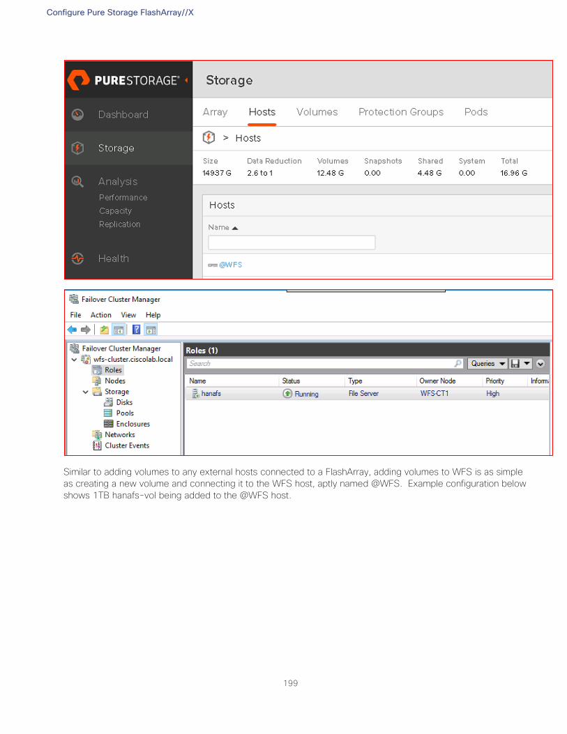
Configure Pure Storage FlashArray//X
199
Similar to adding volumes to any external hosts connected to a FlashArray, adding volumes to WFS is as simple
as creating a new volume and connecting it to the WFS host, aptly named @WFS. Example configuration below
shows 1TB hanafs-vol being added to the @WFS host.
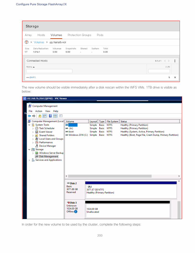
Configure Pure Storage FlashArray//X
200
The new volume should be visible immediately after a disk rescan within the WFS VMs. 1TB drive is visible as
below:
In order for the new volume to be used by the cluster, complete the following steps:
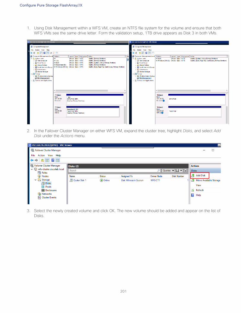
Configure Pure Storage FlashArray//X
201
1. Using Disk Management within a WFS VM, create an NTFS file system for the volume and ensure that both
WFS VMs see the same drive letter. Form the validation setup, 1TB drive appears as Disk 3 in both VMs.
2. In the Failover Cluster Manager on either WFS VM, expand the cluster tree, highlight Disks, and select Add
Disk under the Actions menu.
3. Select the newly created volume and click OK. The new volume should be added and appear on the list of
Disks.
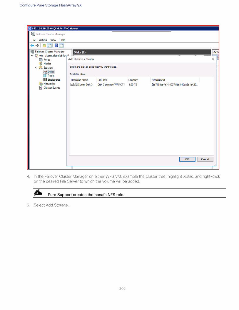
Configure Pure Storage FlashArray//X
202
4. In the Failover Cluster Manager on either WFS VM, example the cluster tree, highlight Roles, and right-click
on the desired File Server to which the volume will be added.
Pure Support creates the hanafs NFS role.
5. Select Add Storage.
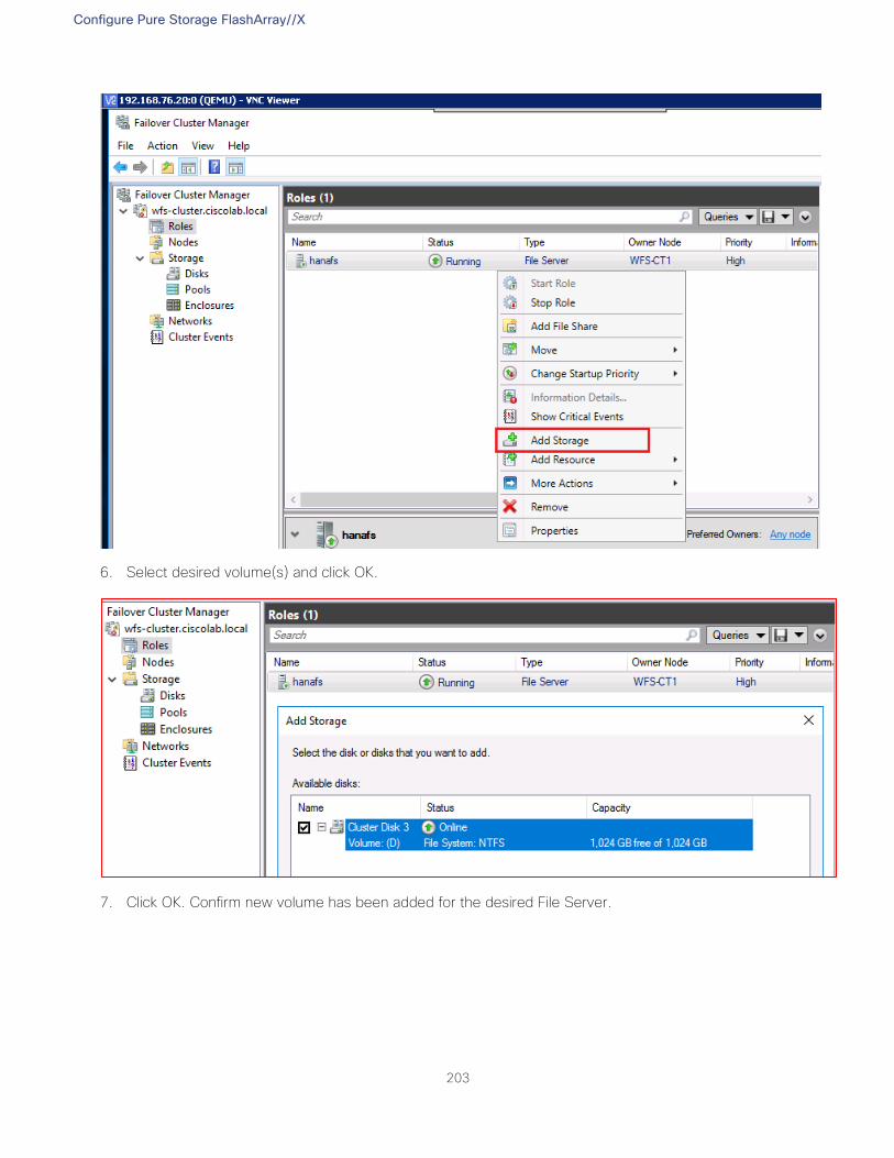
Configure Pure Storage FlashArray//X
203
6. Select desired volume(s) and click OK.
7. Click OK. Confirm new volume has been added for the desired File Server.
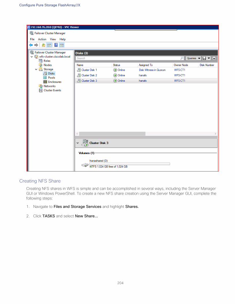
Configure Pure Storage FlashArray//X
204
Creating NFS Share
Creating NFS shares in WFS is simple and can be accomplished in several ways, including the Server Manager
GUI or Windows PowerShell. To create a new NFS share creation using the Server Manager GUI, complete the
following steps:
1. Navigate to Files and Storage Services and highlight Shares.
2. Click TASKS and select New Share…
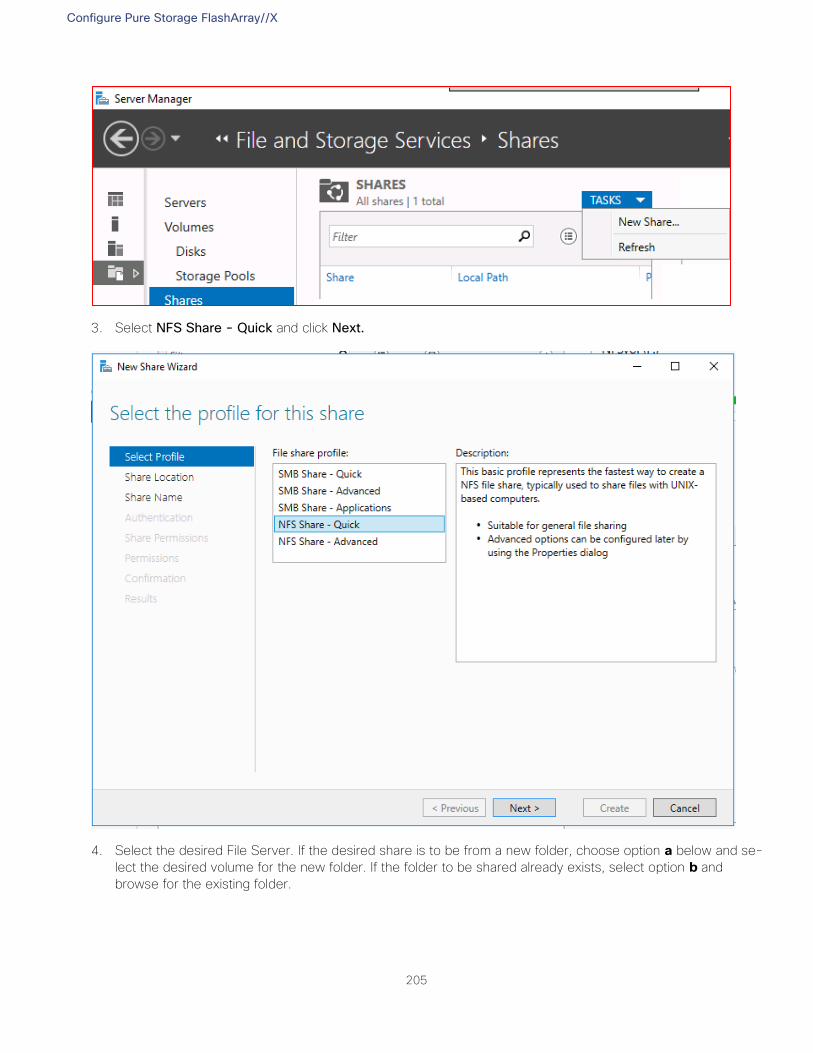
Configure Pure Storage FlashArray//X
205
3. Select NFS Share - Quick and click Next.
4. Select the desired File Server. If the desired share is to be from a new folder, choose option a below and se-
lect the desired volume for the new folder. If the folder to be shared already exists, select option b and
browse for the existing folder.
Configure Pure Storage FlashArray//X
206
5. Click Next.
6. Give the share a name and click Next.
7. Select the Authentication type for the client server. For simplicity, select No server authentication
(AUTH_SYS).
Configure Pure Storage FlashArray//X
207
8. Select Enable unmapped user access and Allow unmapped user access by UID/GID.
You can choose Kerberos v5 authentication as long as it is configured appropriately in your environment.
9. Click Next.
10. Select the client hosts that are allowed to mount the NFS shares. You can select individual host names (or IP
addresses), groups, or all host machines. For simplicity in this example, select All Machines.
11. Set the share permissions to Read/Write.
Configure Pure Storage FlashArray//X
208
12. Click Add.
13. Confirm the selected hosts, groups, or all machines appear. Click Next.
Configure Pure Storage FlashArray//X
209
14. In the next Permissions window, click Customized permissions...
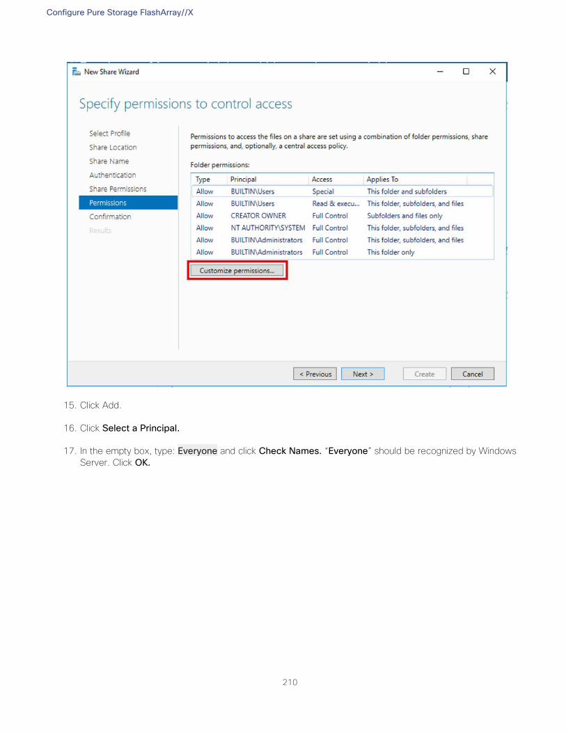
Configure Pure Storage FlashArray//X
210
15. Click Add.
16. Click Select a Principal.
17. In the empty box, type: Everyone and click Check Names. “Everyone” should be recognized by Windows
Server. Click OK.
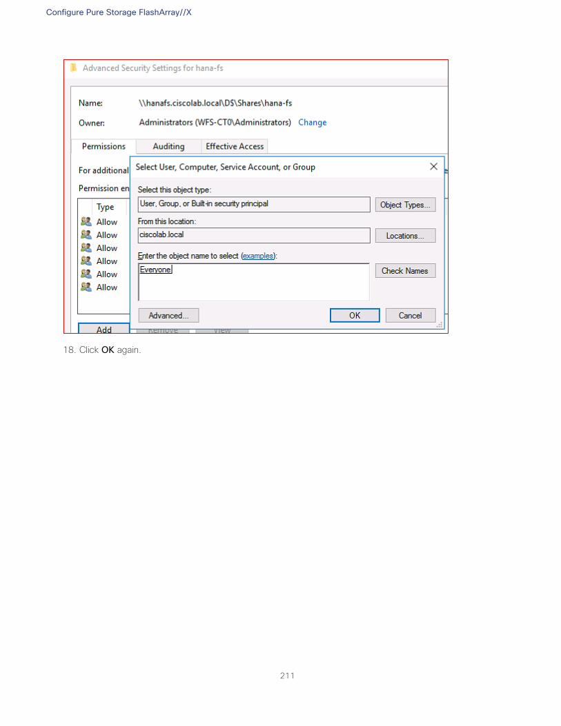
Configure Pure Storage FlashArray//X
211
18. Click OK again.
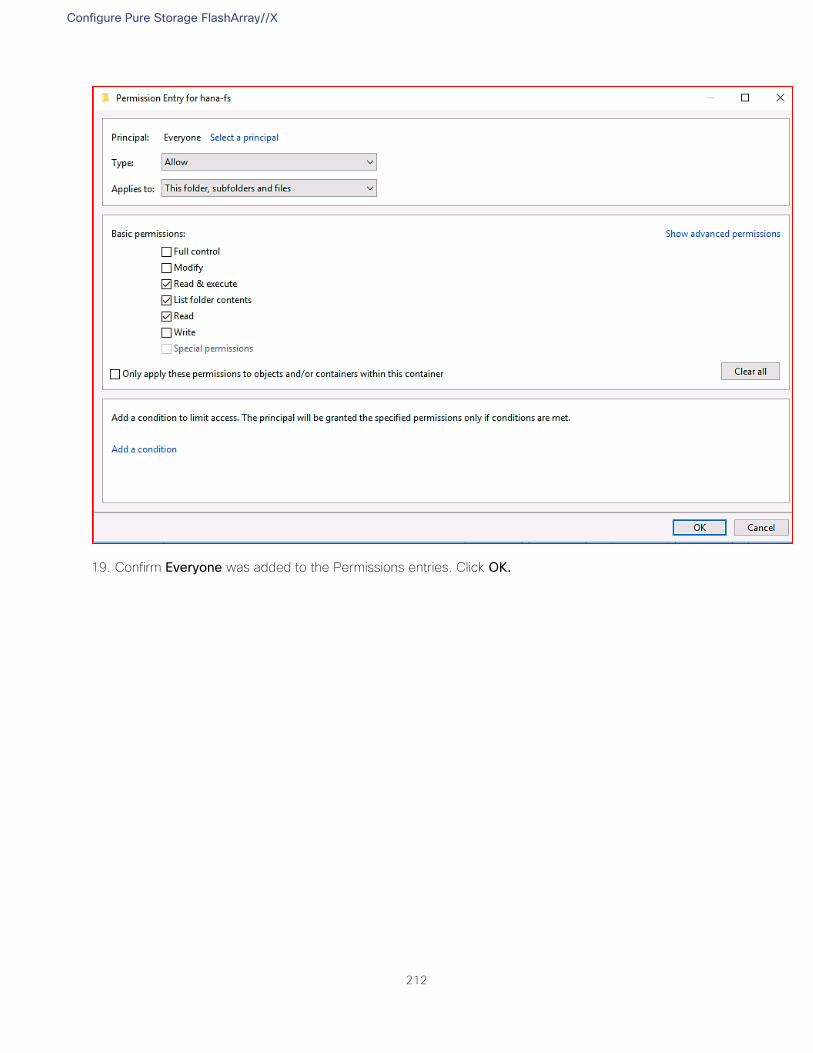
Configure Pure Storage FlashArray//X
212
19. Confirm Everyone was added to the Permissions entries. Click OK.
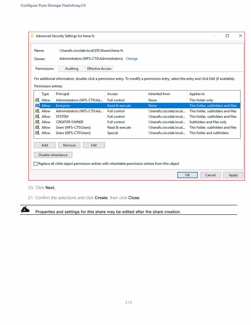
Configure Pure Storage FlashArray//X
213
.
20. Click Next.
21. Confirm the selections and click Create, then click Close.
Properties and settings for this share may be edited after the share creation.
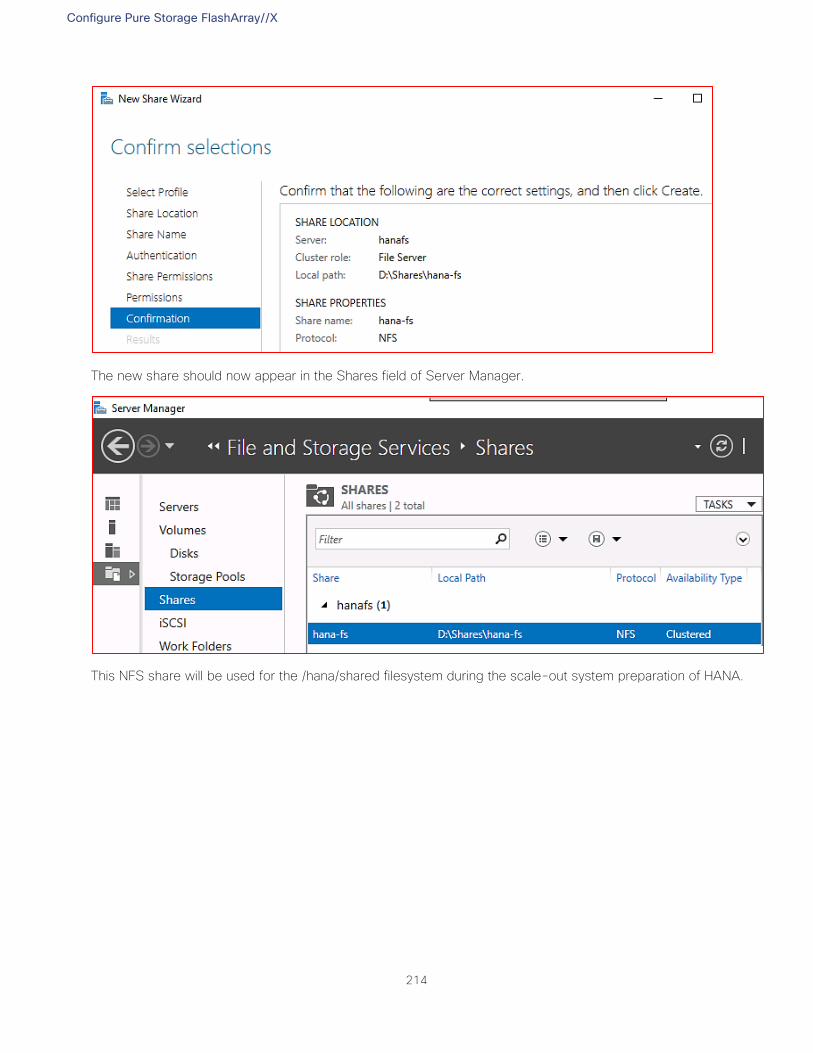
Configure Pure Storage FlashArray//X
214
The new share should now appear in the Shares field of Server Manager.
This NFS share will be used for the /hana/shared filesystem during the scale-out system preparation of HANA.
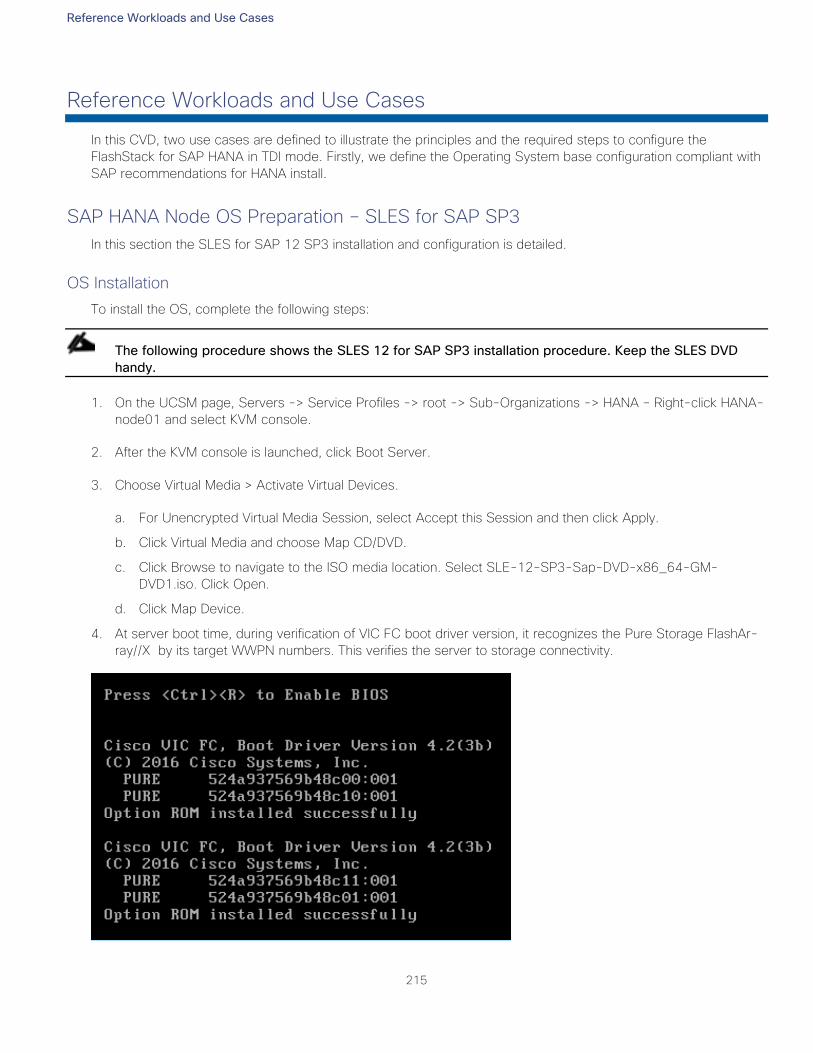
Reference Workloads and Use Cases
215
Reference Workloads and Use Cases
In this CVD, two use cases are defined to illustrate the principles and the required steps to configure the
FlashStack for SAP HANA in TDI mode. Firstly, we define the Operating System base configuration compliant with
SAP recommendations for HANA install.
SAP HANA Node OS Preparation – SLES for SAP SP3
In this section the SLES for SAP 12 SP3 installation and configuration is detailed.
OS Installation
To install the OS, complete the following steps:
The following procedure shows the SLES 12 for SAP SP3 installation procedure. Keep the SLES DVD
handy.
1. On the UCSM page, Servers -> Service Profiles -> root -> Sub-Organizations -> HANA – Right-click HANA-
node01 and select KVM console.
2. After the KVM console is launched, click Boot Server.
3. Choose Virtual Media > Activate Virtual Devices.
a. For Unencrypted Virtual Media Session, select Accept this Session and then click Apply.
b. Click Virtual Media and choose Map CD/DVD.
c. Click Browse to navigate to the ISO media location. Select SLE-12-SP3-Sap-DVD-x86_64-GM-
DVD1.iso. Click Open.
d. Click Map Device.
4. At server boot time, during verification of VIC FC boot driver version, it recognizes the Pure Storage FlashAr-
ray//X by its target WWPN numbers. This verifies the server to storage connectivity.
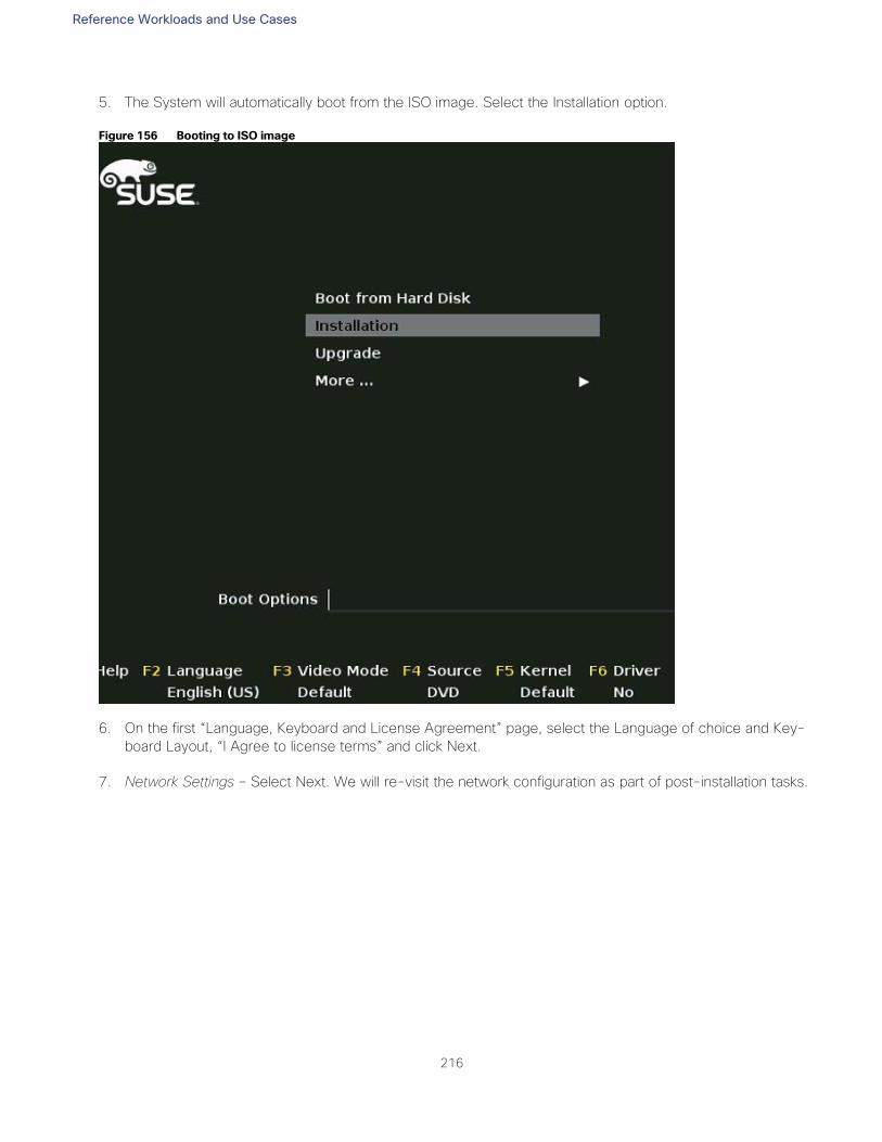
Reference Workloads and Use Cases
216
5. The System will automatically boot from the ISO image. Select the Installation option.
Figure 156 Booting to ISO image
6. On the first “Language, Keyboard and License Agreement” page, select the Language of choice and Key-
board Layout, “I Agree to license terms” and click Next.
7. Network Settings – Select Next. We will re-visit the network configuration as part of post-installation tasks.
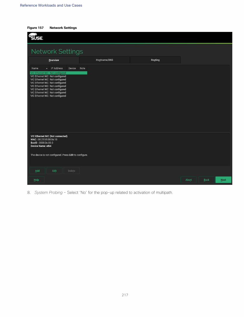
Reference Workloads and Use Cases
217
Figure 157 Network Settings
8. System Probing – Select ‘No’ for the pop-up related to activation of multipath.
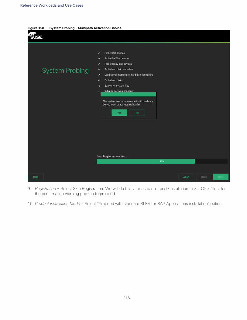
Reference Workloads and Use Cases
218
Figure 158 System Probing – Multipath Activation Choice
9. Registration – Select Skip Registration. We will do this later as part of post-installation tasks. Click ‘Yes’ for
the confirmation warning pop-up to proceed.
10. Product Installation Mode – Select “Proceed with standard SLES for SAP Applications installation” option.
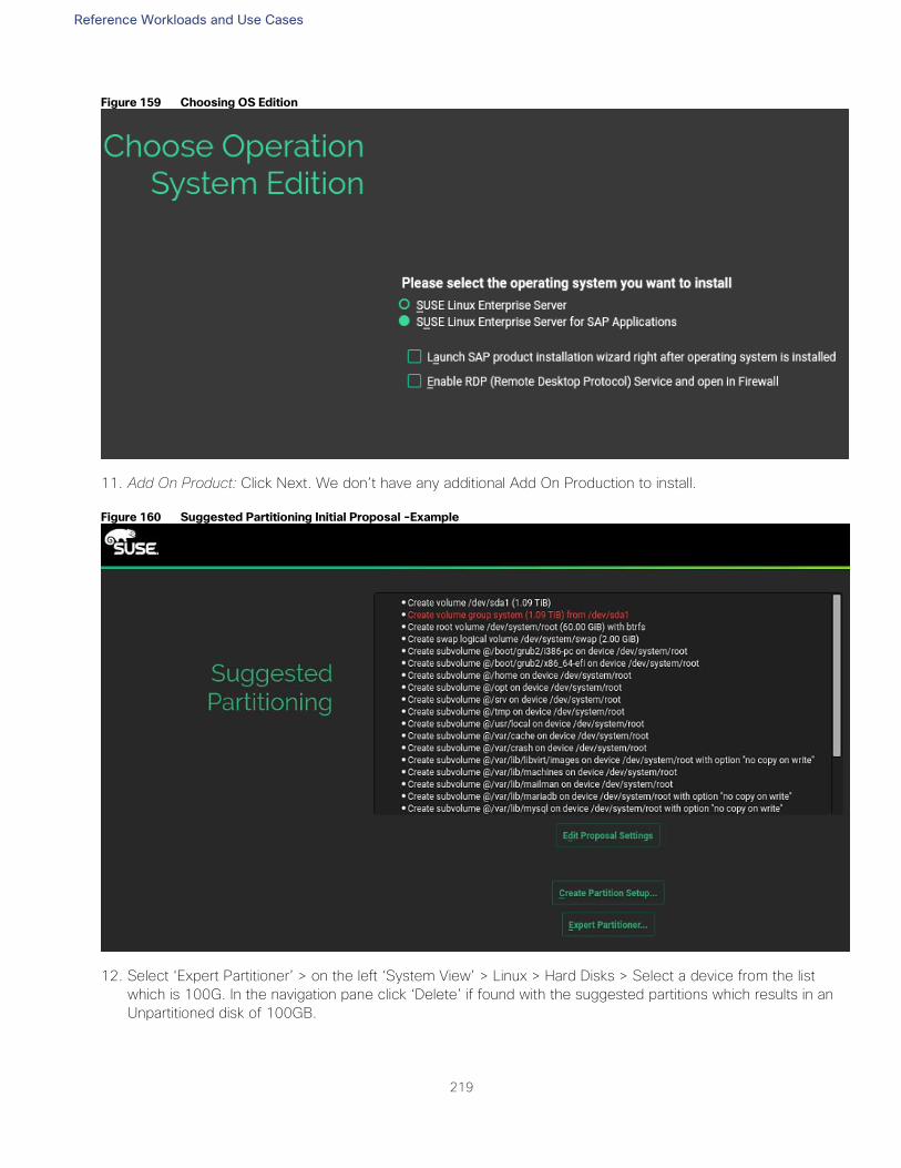
Reference Workloads and Use Cases
219
Figure 159 Choosing OS Edition
11. Add On Product: Click Next. We don’t have any additional Add On Production to install.
Figure 160 Suggested Partitioning Initial Proposal -Example
12. Select ‘Expert Partitioner’ > on the left ‘System View’ > Linux > Hard Disks > Select a device from the list
which is 100G. In the navigation pane click ‘Delete’ if found with the suggested partitions which results in an
Unpartitioned disk of 100GB.
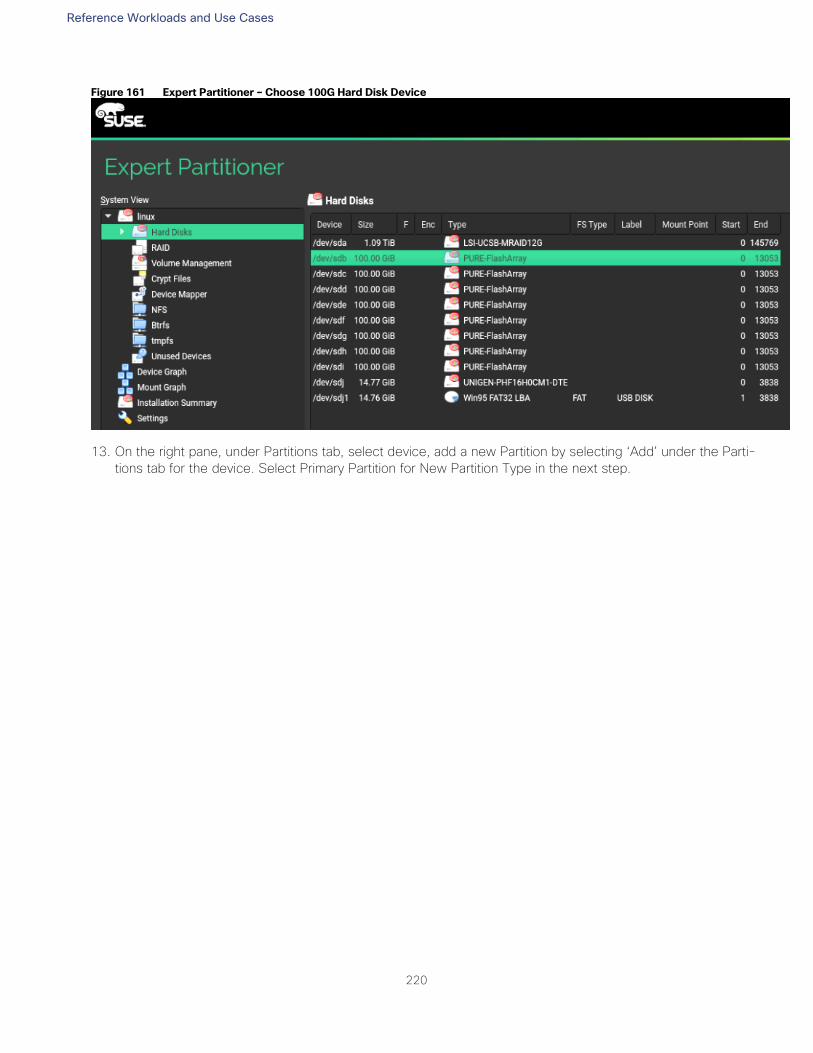
Reference Workloads and Use Cases
220
Figure 161 Expert Partitioner – Choose 100G Hard Disk Device
13. On the right pane, under Partitions tab, select device, add a new Partition by selecting ‘Add’ under the Parti-
tions tab for the device. Select Primary Partition for New Partition Type in the next step.
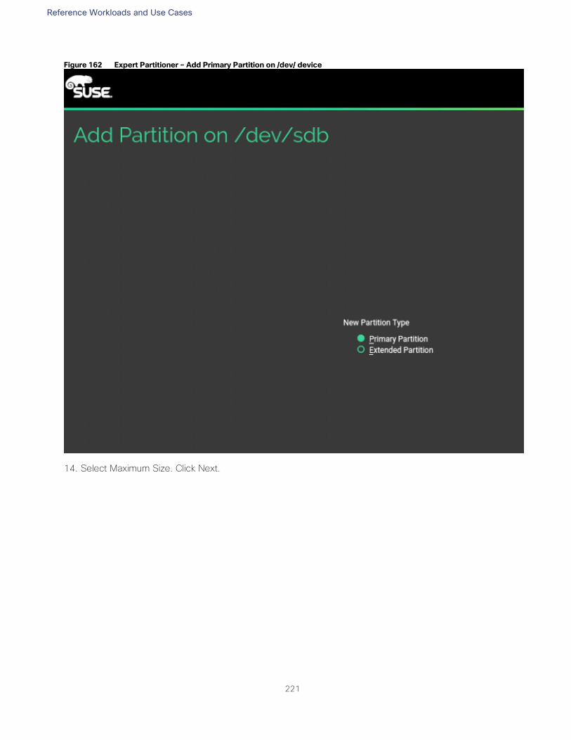
Reference Workloads and Use Cases
221
Figure 162 Expert Partitioner – Add Primary Partition on /dev/ device
14. Select Maximum Size. Click Next.
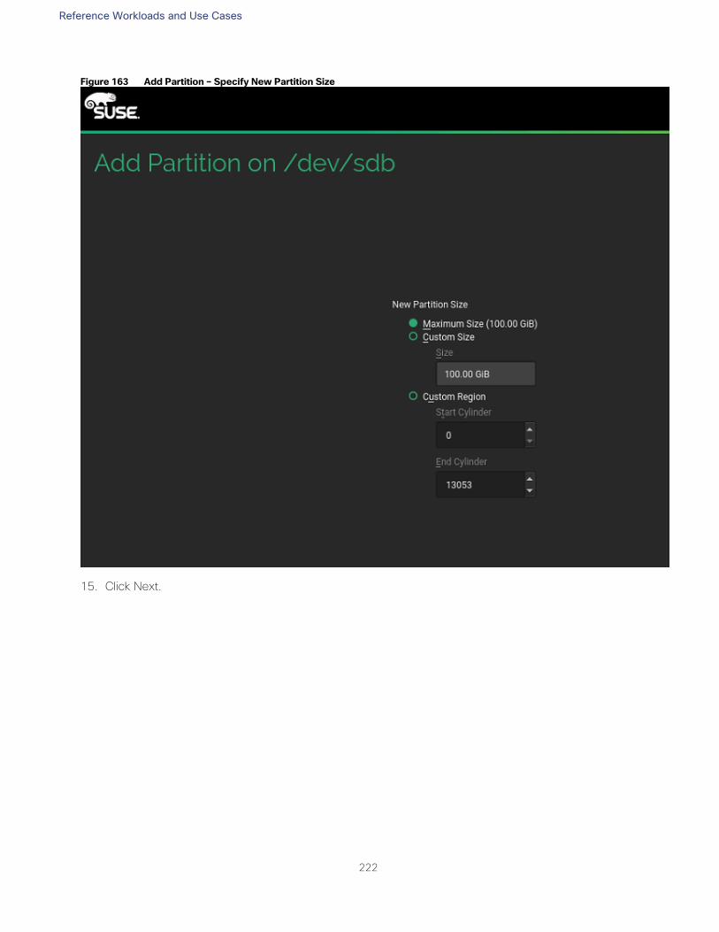
Reference Workloads and Use Cases
222
Figure 163 Add Partition – Specify New Partition Size
15. Click Next.
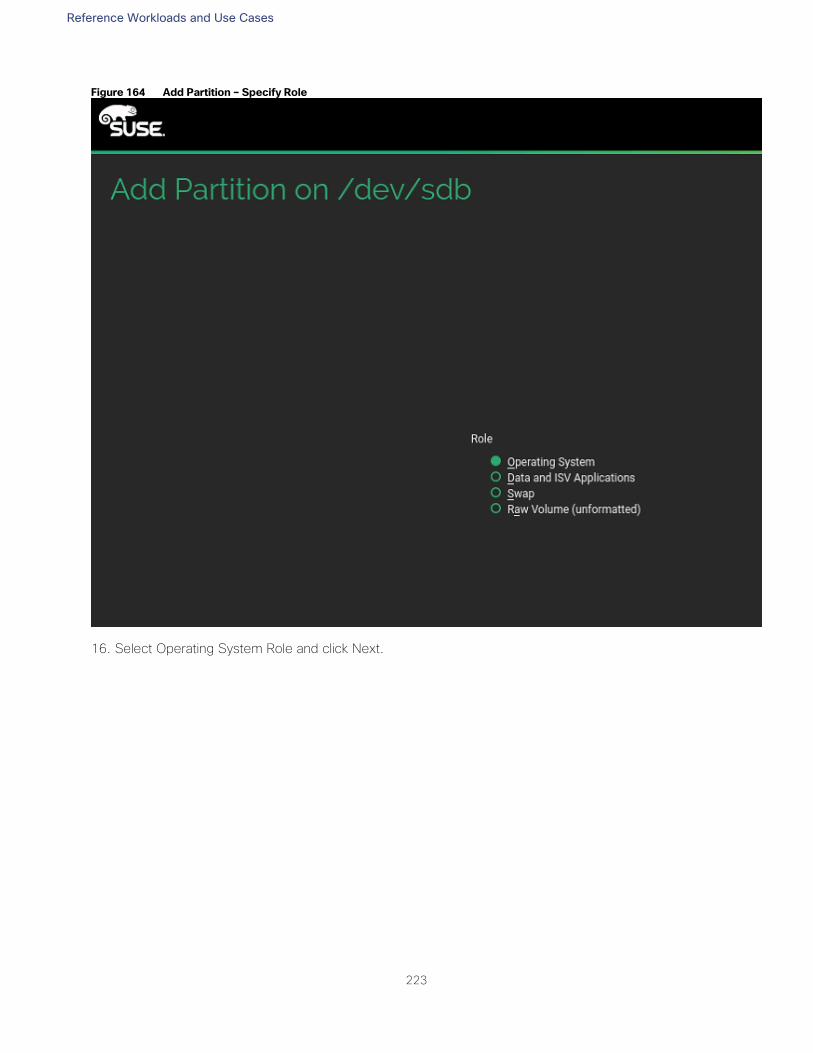
Reference Workloads and Use Cases
223
Figure 164 Add Partition – Specify Role
16. Select Operating System Role and click Next.
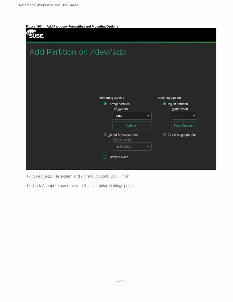
Reference Workloads and Use Cases
224
Figure 165 Add Partition- Formatting and Mounting Options
17. Select ext3 File system and / or mount point. Click Finish.
18. Click Accept to come back to the Installation Settings page.
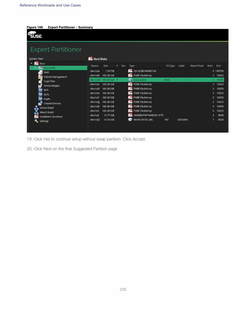
Reference Workloads and Use Cases
225
Figure 166 Expert Partitioner – Summary
19. Click Yes to continue setup without swap partition. Click Accept.
20. Click Next on the final Suggested Partition page.
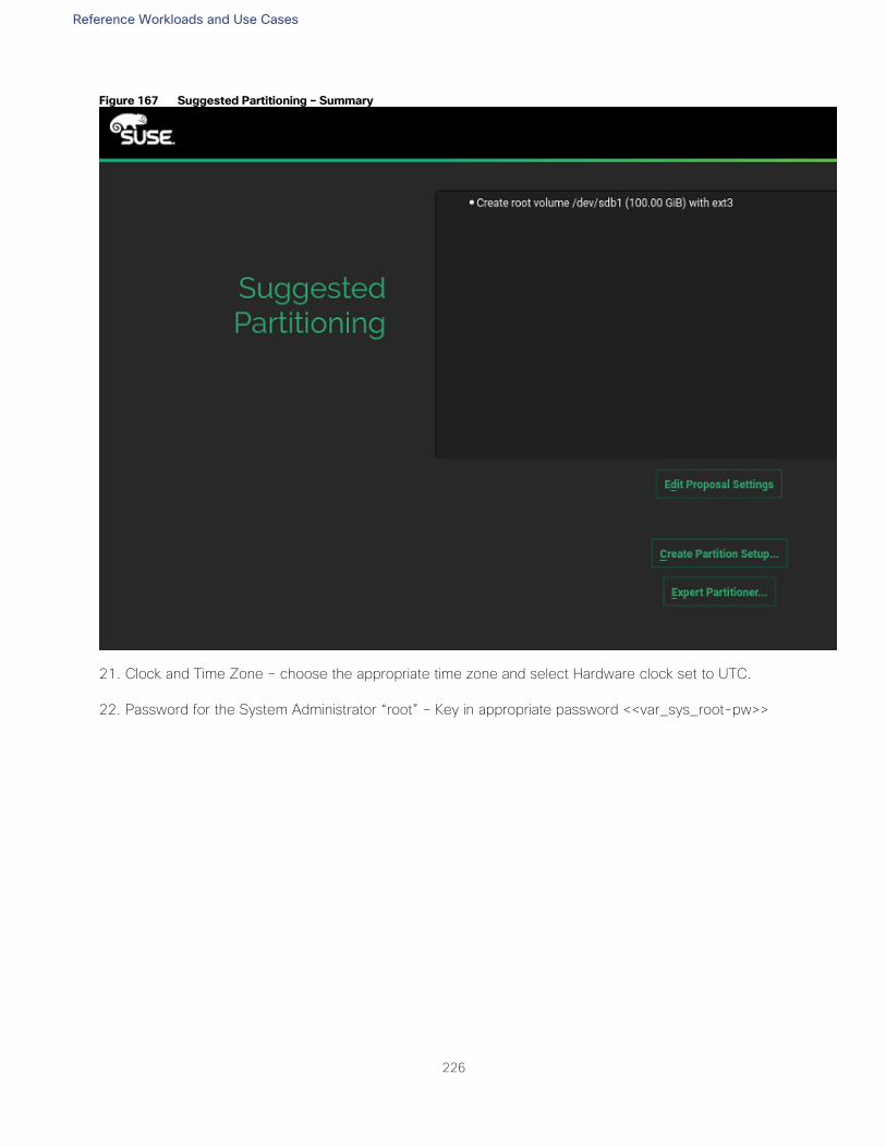
Reference Workloads and Use Cases
226
Figure 167 Suggested Partitioning – Summary
21. Clock and Time Zone – choose the appropriate time zone and select Hardware clock set to UTC.
22. Password for the System Administrator “root” – Key in appropriate password <<var_sys_root-pw>>
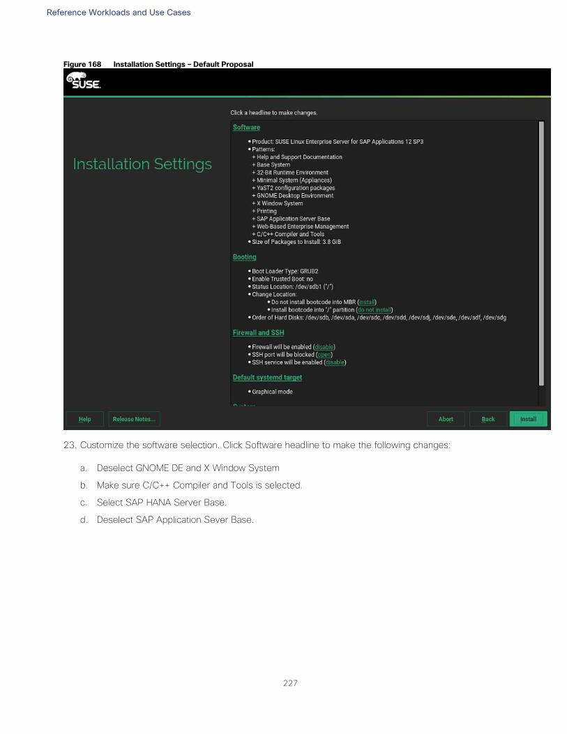
Reference Workloads and Use Cases
227
Figure 168 Installation Settings – Default Proposal
23. Customize the software selection. Click Software headline to make the following changes:
a. Deselect GNOME DE and X Window System
b. Make sure C/C++ Compiler and Tools is selected.
c. Select SAP HANA Server Base.
d. Deselect SAP Application Sever Base.
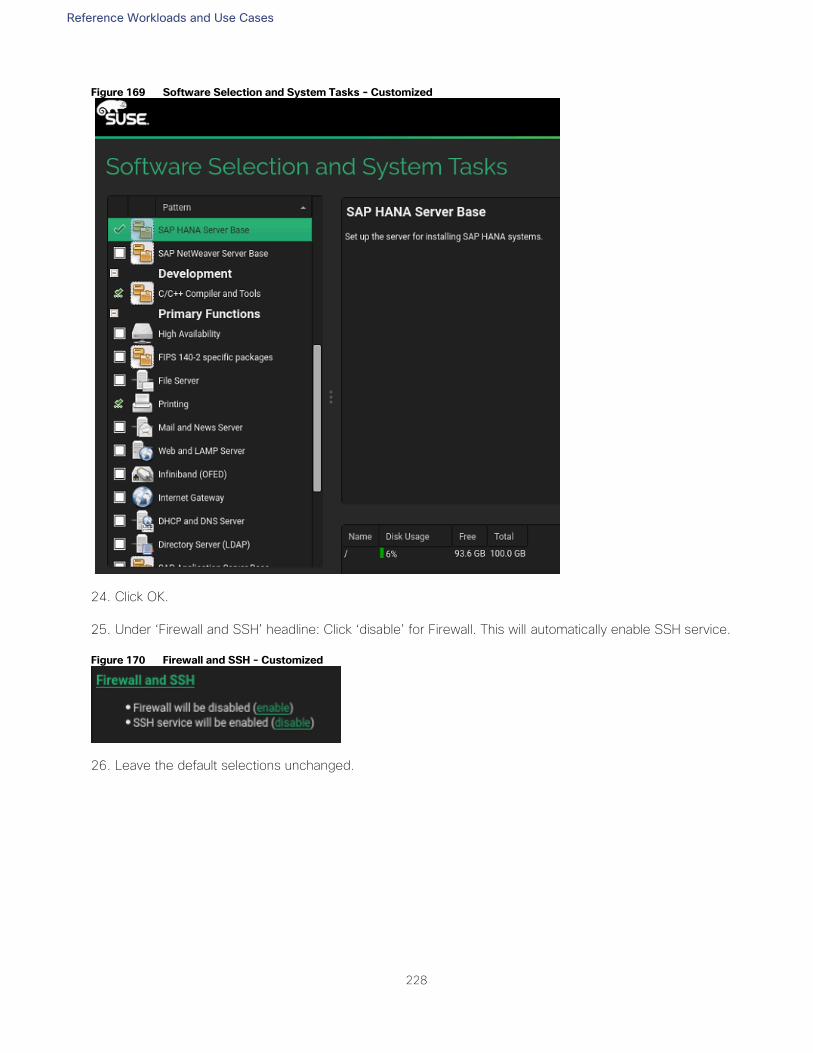
Reference Workloads and Use Cases
228
Figure 169 Software Selection and System Tasks - Customized
24. Click OK.
25. Under ‘Firewall and SSH’ headline: Click ‘disable’ for Firewall. This will automatically enable SSH service.
Figure 170 Firewall and SSH - Customized
26. Leave the default selections unchanged.
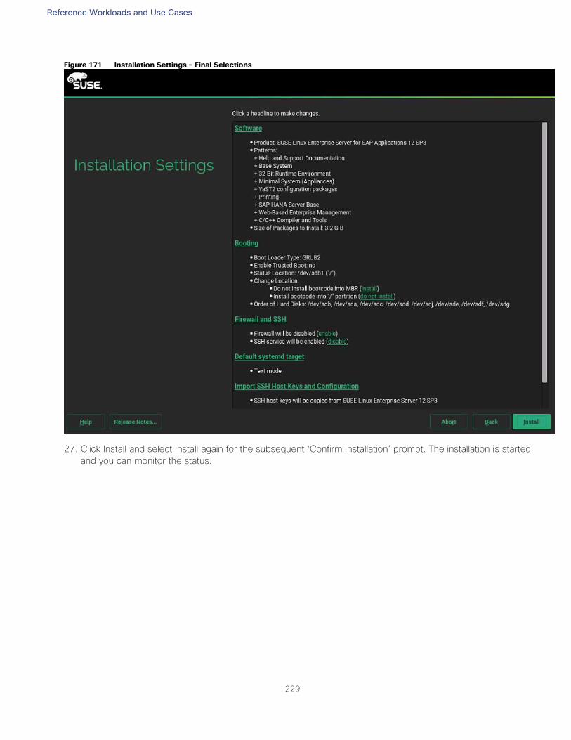
Reference Workloads and Use Cases
229
Figure 171 Installation Settings – Final Selections
27. Click Install and select Install again for the subsequent ‘Confirm Installation’ prompt. The installation is started
and you can monitor the status.
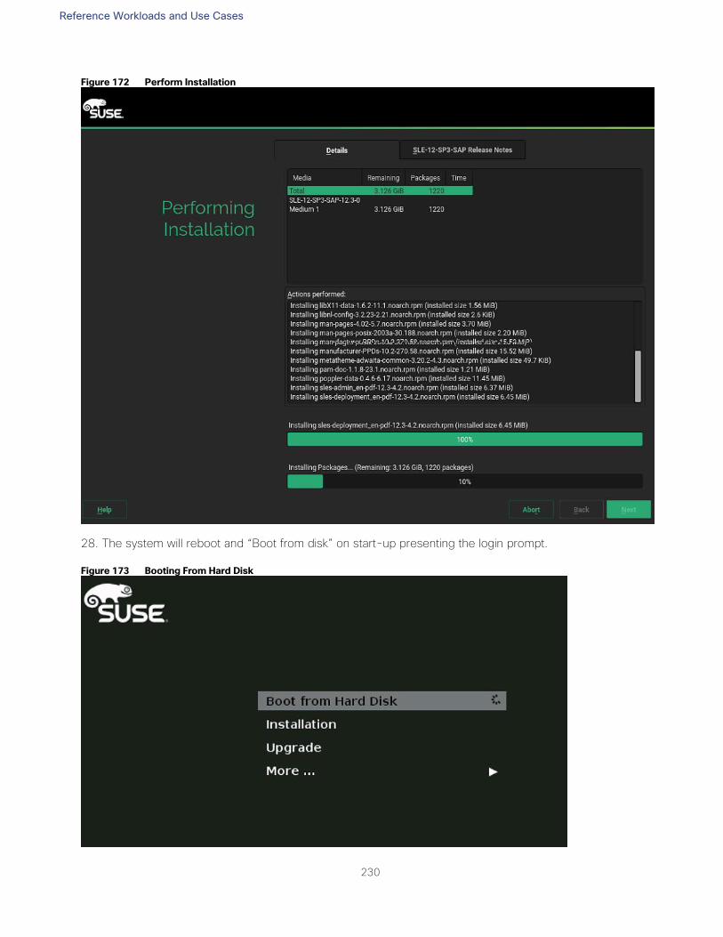
Reference Workloads and Use Cases
230
Figure 172 Perform Installation
28. The system will reboot and “Boot from disk” on start-up presenting the login prompt.
Figure 173 Booting From Hard Disk
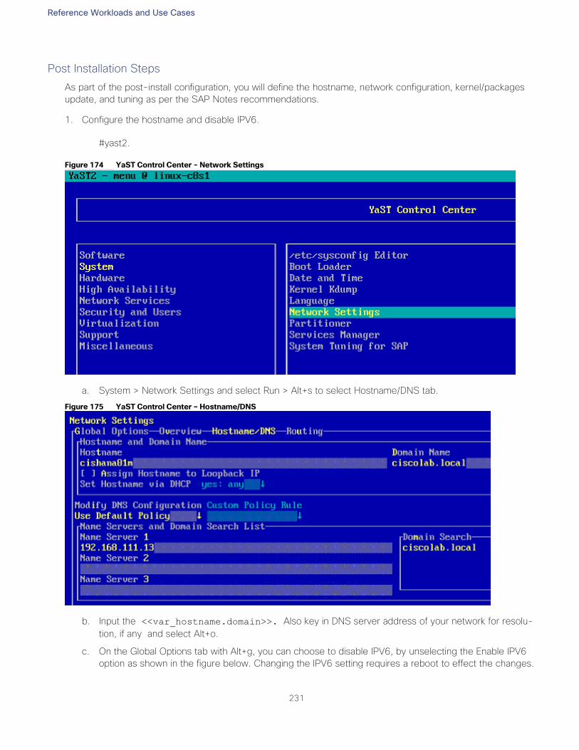
Reference Workloads and Use Cases
231
Post Installation Steps
As part of the post-install configuration, you will define the hostname, network configuration, kernel/packages
update, and tuning as per the SAP Notes recommendations.
1. Configure the hostname and disable IPV6.
#yast2.
Figure 174 YaST Control Center - Network Settings
a. System > Network Settings and select Run > Alt+s to select Hostname/DNS tab.
Figure 175 YaST Control Center – Hostname/DNS
b. Input the <<var_hostname.domain>>. Also key in DNS server address of your network for resolu-
tion, if any and select Alt+o.
c. On the Global Options tab with Alt+g, you can choose to disable IPV6, by unselecting the Enable IPV6
option as shown in the figure below. Changing the IPV6 setting requires a reboot to effect the changes.
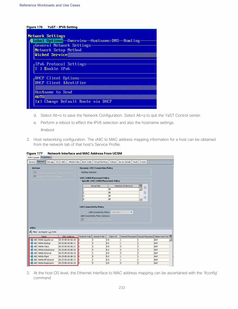
Reference Workloads and Use Cases
232
Figure 176 YaST - IPV6 Setting
d. Select Alt+o to save the Network Configuration. Select Alt+q to quit the YaST Control center.
e. Perform a reboot to effect the IPV6 selection and also the hostname settings.
#reboot
2. Host networking configuration. The vNIC to MAC address mapping information for a host can be obtained
from the network tab of that host’s Service Profile.
Figure 177 Network Interface and MAC Address From UCSM
3. At the host OS level, the Ethernet interface to MAC address mapping can be ascertained with the ‘ifconfig’
command
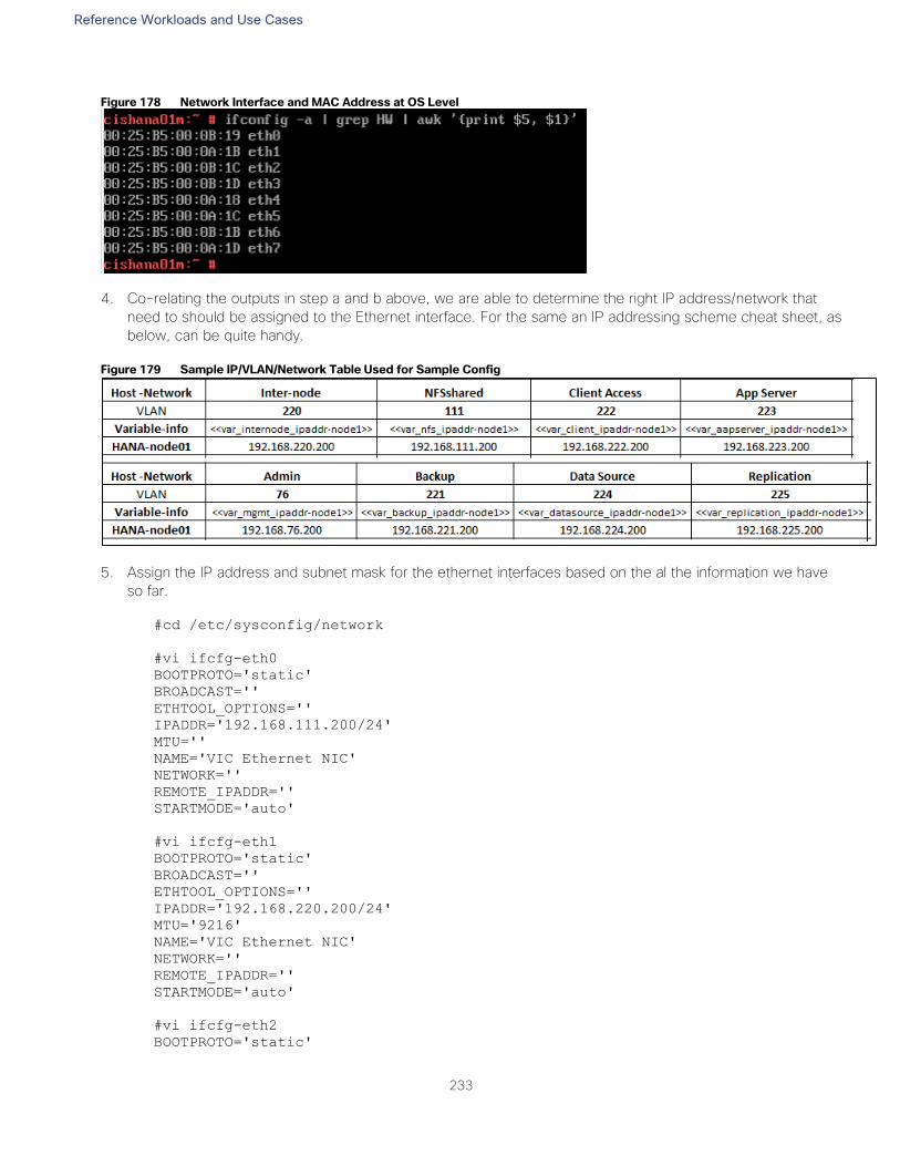
Reference Workloads and Use Cases
233
Figure 178 Network Interface and MAC Address at OS Level
4. Co-relating the outputs in step a and b above, we are able to determine the right IP address/network that
need to should be assigned to the Ethernet interface. For the same an IP addressing scheme cheat sheet, as
below, can be quite handy.
Figure 179 Sample IP/VLAN/Network Table Used for Sample Config
5. Assign the IP address and subnet mask for the ethernet interfaces based on the al the information we have
so far.
#cd /etc/sysconfig/network
#vi ifcfg-eth0
BOOTPROTO='static'
BROADCAST=''
ETHTOOL_OPTIONS=''
IPADDR='192.168.111.200/24'
MTU=''
NAME='VIC Ethernet NIC'
NETWORK=''
REMOTE_IPADDR=''
STARTMODE='auto'
#vi ifcfg-eth1
BOOTPROTO='static'
BROADCAST=''
ETHTOOL_OPTIONS=''
IPADDR='192.168.220.200/24'
MTU='9216'
NAME='VIC Ethernet NIC'
NETWORK=''
REMOTE_IPADDR=''
STARTMODE='auto'
#vi ifcfg-eth2
BOOTPROTO='static'
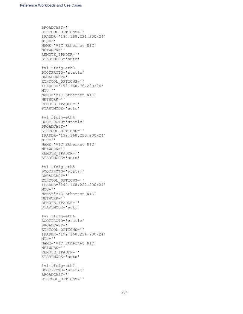
Reference Workloads and Use Cases
234
BROADCAST=''
ETHTOOL_OPTIONS=''
IPADDR='192.168.221.200/24'
MTU=''
NAME='VIC Ethernet NIC'
NETWORK=''
REMOTE_IPADDR=''
STARTMODE='auto'
#vi ifcfg-eth3
BOOTPROTO='static'
BROADCAST=''
ETHTOOL_OPTIONS=''
IPADDR='192.168.76.200/24'
MTU=''
NAME='VIC Ethernet NIC'
NETWORK=''
REMOTE_IPADDR=''
STARTMODE='auto'
#vi ifcfg-eth4
BOOTPROTO='static'
BROADCAST=''
ETHTOOL_OPTIONS=''
IPADDR='192.168.223.200/24'
MTU=''
NAME='VIC Ethernet NIC'
NETWORK=''
REMOTE_IPADDR=''
STARTMODE='auto'
#vi ifcfg-eth5
BOOTPROTO='static'
BROADCAST=''
ETHTOOL_OPTIONS=''
IPADDR='192.168.222.200/24'
MTU=''
NAME='VIC Ethernet NIC'
NETWORK=''
REMOTE_IPADDR=''
STARTMODE='auto
#vi ifcfg-eth6
BOOTPROTO='static'
BROADCAST=''
ETHTOOL_OPTIONS=''
IPADDR='192.168.224.200/24'
MTU=''
NAME='VIC Ethernet NIC'
NETWORK=''
REMOTE_IPADDR=''
STARTMODE='auto'
#vi ifcfg-eth7
BOOTPROTO='static'
BROADCAST=''
ETHTOOL_OPTIONS=''
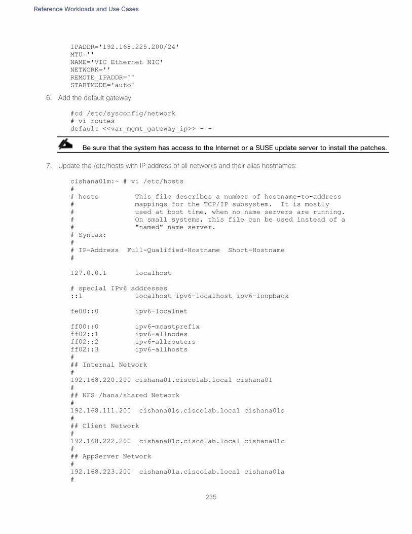
Reference Workloads and Use Cases
235
IPADDR='192.168.225.200/24'
MTU=''
NAME='VIC Ethernet NIC'
NETWORK=''
REMOTE_IPADDR=''
STARTMODE='auto'
6. Add the default gateway.
#cd /etc/sysconfig/network
# vi routes
default <<var_mgmt_gateway_ip>> - -
Be sure that the system has access to the Internet or a SUSE update server to install the patches.
7. Update the /etc/hosts with IP address of all networks and their alias hostnames:
cishana01m:~ # vi /etc/hosts
#
# hosts This file describes a number of hostname-to-address
# mappings for the TCP/IP subsystem. It is mostly
# used at boot time, when no name servers are running.
# On small systems, this file can be used instead of a
# "named" name server.
# Syntax:
#
# IP-Address Full-Qualified-Hostname Short-Hostname
#
127.0.0.1 localhost
# special IPv6 addresses
::1 localhost ipv6-localhost ipv6-loopback
fe00::0 ipv6-localnet
ff00::0 ipv6-mcastprefix
ff02::1 ipv6-allnodes
ff02::2 ipv6-allrouters
ff02::3 ipv6-allhosts
#
## Internal Network
#
192.168.220.200 cishana01.ciscolab.local cishana01
#
## NFS /hana/shared Network
#
192.168.111.200 cishana01s.ciscolab.local cishana01s
#
## Client Network
#
192.168.222.200 cishana01c.ciscolab.local cishana01c
#
## AppServer Network
#
192.168.223.200 cishana01a.ciscolab.local cishana01a
#
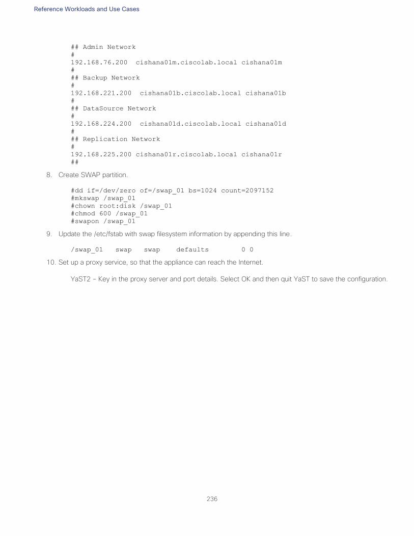
Reference Workloads and Use Cases
236
## Admin Network
#
192.168.76.200 cishana01m.ciscolab.local cishana01m
#
## Backup Network
#
192.168.221.200 cishana01b.ciscolab.local cishana01b
#
## DataSource Network
#
192.168.224.200 cishana01d.ciscolab.local cishana01d
#
## Replication Network
#
192.168.225.200 cishana01r.ciscolab.local cishana01r
##
8. Create SWAP partition.
#dd if=/dev/zero of=/swap_01 bs=1024 count=2097152
#mkswap /swap_01
#chown root:disk /swap_01
#chmod 600 /swap_01
#swapon /swap_01
9. Update the /etc/fstab with swap filesystem information by appending this line.
/swap_01 swap swap defaults 0 0
10. Set up a proxy service, so that the appliance can reach the Internet.
YaST2 – Key in the proxy server and port details. Select OK and then quit YaST to save the configuration.
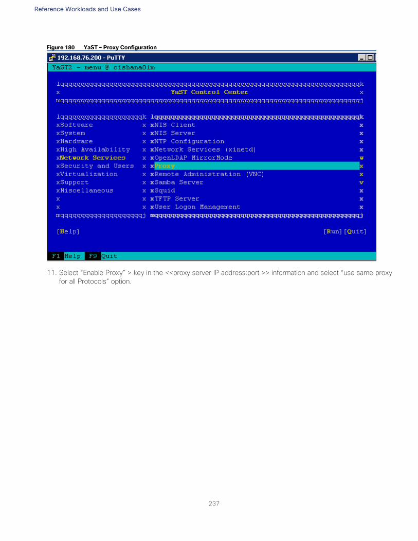
Reference Workloads and Use Cases
237
Figure 180 YaST – Proxy Configuration
11. Select “Enable Proxy” > key in the <<proxy server IP address:port >> information and select “use same proxy
for all Protocols” option.
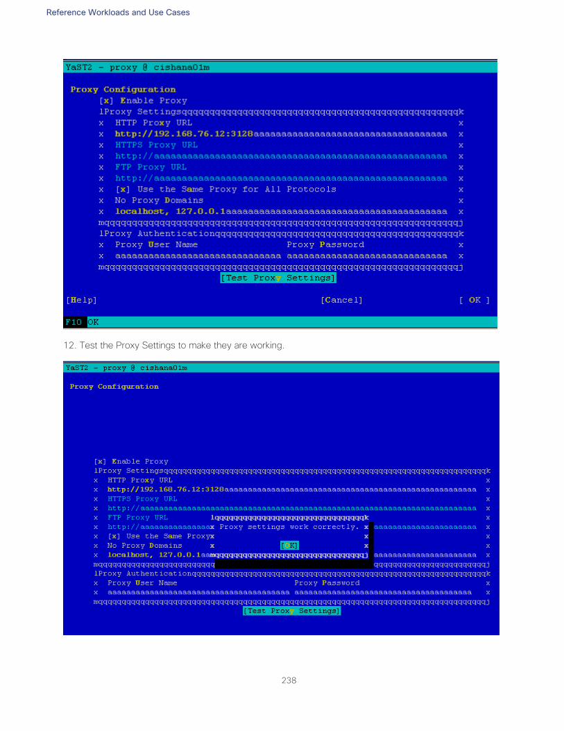
Reference Workloads and Use Cases
238
12. Test the Proxy Settings to make they are working.
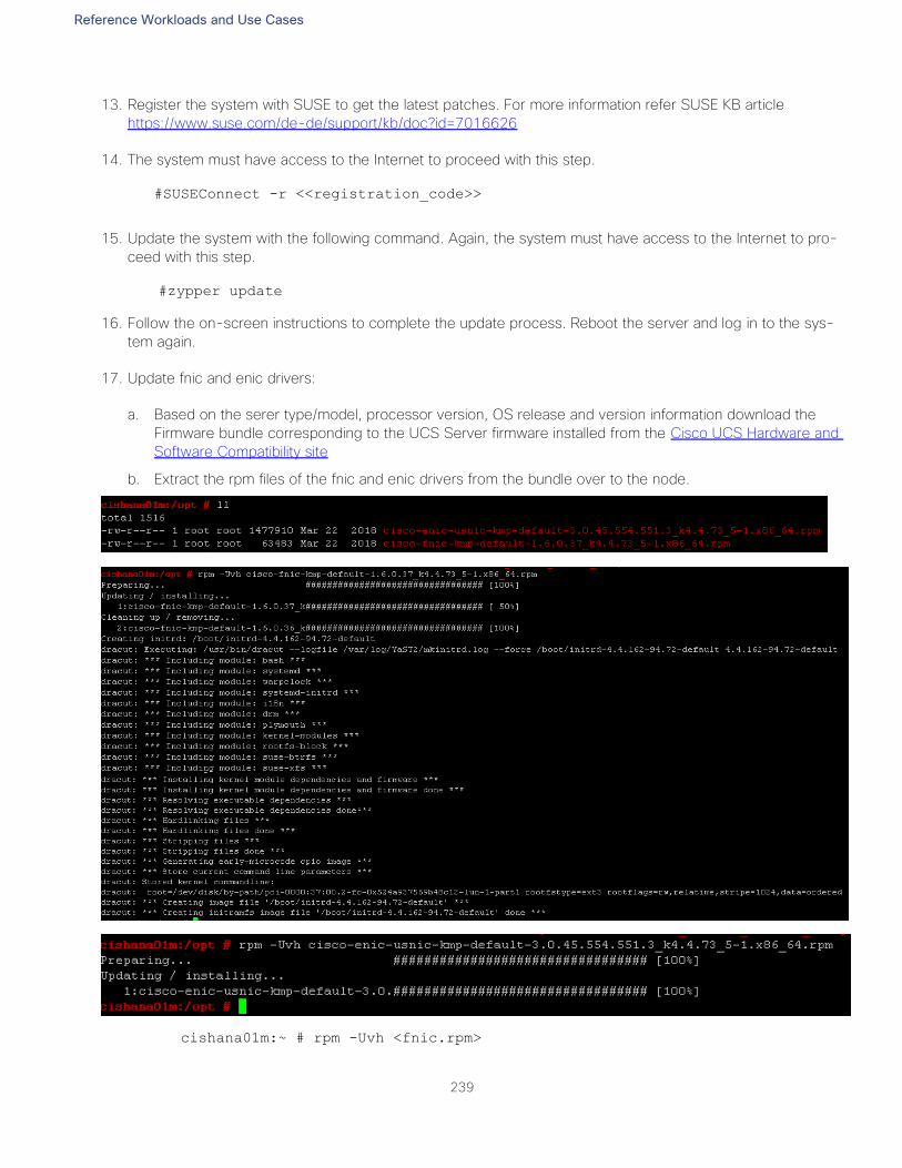
Reference Workloads and Use Cases
239
13. Register the system with SUSE to get the latest patches. For more information refer SUSE KB article
https://www.suse.com/de-de/support/kb/doc?id=7016626
14. The system must have access to the Internet to proceed with this step.
#SUSEConnect -r <<registration_code>>
15. Update the system with the following command. Again, the system must have access to the Internet to pro-
ceed with this step.
#zypper update
16. Follow the on-screen instructions to complete the update process. Reboot the server and log in to the sys-
tem again.
17. Update fnic and enic drivers:
a. Based on the serer type/model, processor version, OS release and version information download the
Firmware bundle corresponding to the UCS Server firmware installed from the Cisco UCS Hardware and
Software Compatibility site
b. Extract the rpm files of the fnic and enic drivers from the bundle over to the node.
cishana01m:~ # rpm -Uvh <fnic.rpm>
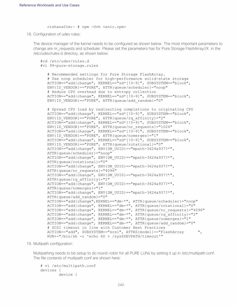
Reference Workloads and Use Cases
240
cishana01m:~ # rpm -Uvh <enic.rpm>
18. Configuration of udev rules:
The device manager of the kernel needs to be configured as shown below. The most important parameters to
change are nr_requests and scheduler. Please set the parameters has for Pure Storage FlashArray//X in the
/etc/udev/rules.d directoy, as shown below:
#cd /etc/udev/rules.d
#vi 99-pure-storage.rules
# Recommended settings for Pure Storage FlashArray.
# Use noop scheduler for high-performance solid-state storage
ACTION=="add|change", KERNEL=="sd*[!0-9]", SUBSYSTEM=="block",
ENV{ID_VENDOR}=="PURE", ATTR{queue/scheduler}="noop"
# Reduce CPU overhead due to entropy collection
ACTION=="add|change", KERNEL=="sd*[!0-9]", SUBSYSTEM=="block",
ENV{ID_VENDOR}=="PURE", ATTR{queue/add_random}="0"
# Spread CPU load by redirecting completions to originating CPU
ACTION=="add|change", KERNEL=="sd*[!0-9]", SUBSYSTEM=="block",
ENV{ID_VENDOR}=="PURE", ATTR{queue/rq_affinity}="2"
ACTION=="add|change", KERNEL=="sd*[!0-9]", SUBSYSTEM=="block",
ENV{ID_VENDOR}=="PURE", ATTR{queue/nr_requests}="1024"
ACTION=="add|change", KERNEL=="sd*[!0-9]", SUBSYSTEM=="block",
ENV{ID_VENDOR}=="PURE", ATTR{queue/nomerges}="1"
ACTION=="add|change", KERNEL=="sd*[!0-9]", SUBSYSTEM=="block",
ENV{ID_VENDOR}=="PURE", ATTR{queue/rotational}="0"
ACTION=="add|change", ENV{DM_UUID}=="mpath-3624a937?*",
ATTR{queue/scheduler}="noop"
ACTION=="add|change", ENV{DM_UUID}=="mpath-3624a937?*",
ATTR{queue/rotational}="0"
ACTION=="add|change", ENV{DM_UUID}=="mpath-3624a937?*",
ATTR{queue/nr_requests}="4096"
ACTION=="add|change", ENV{DM_UUID}=="mpath-3624a937?*",
ATTR{queue/rq_affinity}="2"
ACTION=="add|change", ENV{DM_UUID}=="mpath-3624a937?*",
ATTR{queue/nomerges}="1"
ACTION=="add|change", ENV{DM_UUID}=="mpath-3624a937?*",
ATTR{queue/add_random}="0"
ACTION=="add|change",KERNEL=="dm-*", ATTR{queue/scheduler}="noop"
ACTION=="add|change", KERNEL=="dm-*", ATTR{queue/rotational}="0"
ACTION=="add|change", KERNEL=="dm-*", ATTR{queue/nr_requests}="4096"
ACTION=="add|change", KERNEL=="dm-*", ATTR{queue/rq_affinity}="2"
ACTION=="add|change", KERNEL=="dm-*", ATTR{queue/nomerges}="1"
ACTION=="add|change", KERNEL=="dm-*", ATTR{queue/add_random}="0"
# SCSI timeout in line with Customer Best Practices
ACTION=="add", SUBSYSTEM=="scsi", ATTRS{model}=="FlashArray ",
RUN+="/bin/sh -c 'echo 60 > /sys$DEVPATH/timeout'"
19. Multipath configuration:
Multipathing needs to be setup to do round-robin for all PURE LUNs by setting it up in /etc/multipath.conf.
The file contents of multipath.conf are shown here:
# vi /etc/multipath.conf
devices {
device {
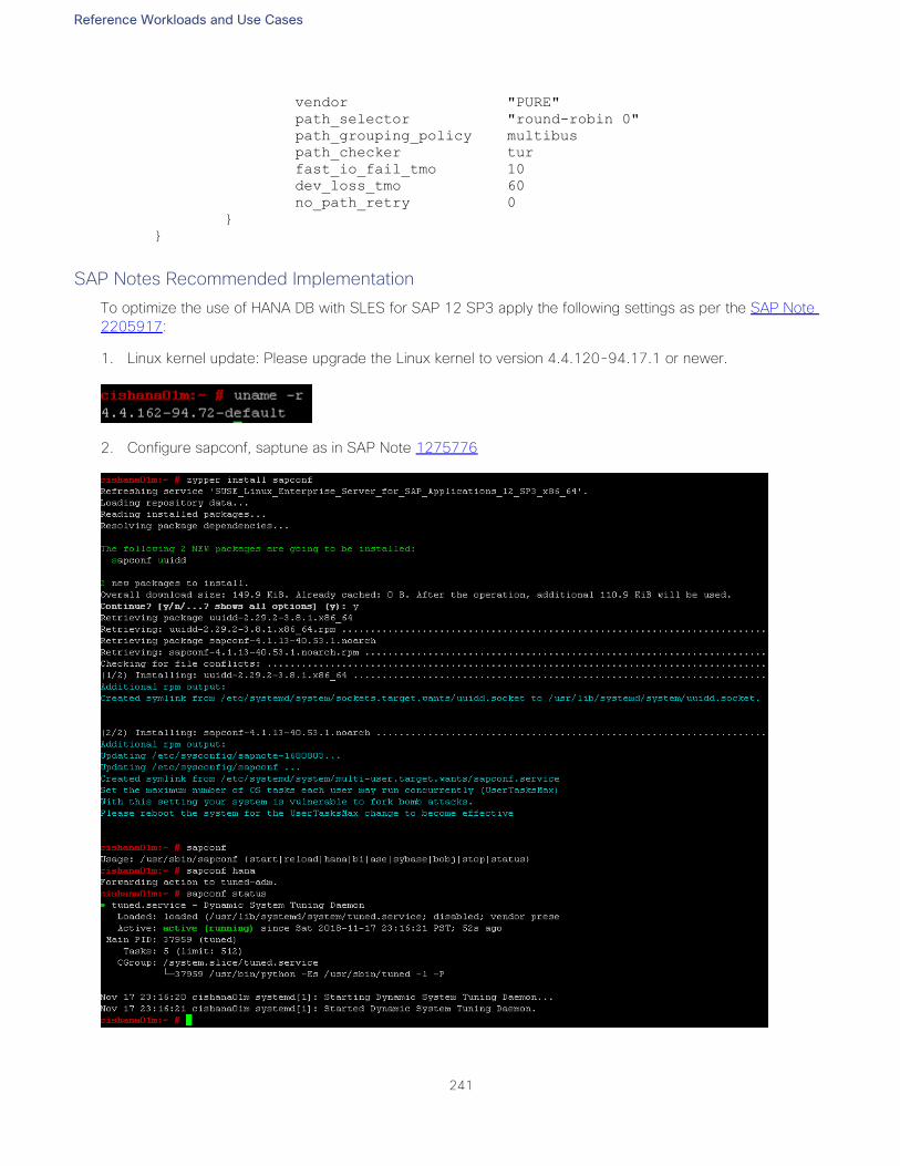
Reference Workloads and Use Cases
241
vendor "PURE"
path_selector "round-robin 0"
path_grouping_policy multibus
path_checker tur
fast_io_fail_tmo 10
dev_loss_tmo 60
no_path_retry 0
}
}
SAP Notes Recommended Implementation
To optimize the use of HANA DB with SLES for SAP 12 SP3 apply the following settings as per the SAP Note
2205917:
1. Linux kernel update: Please upgrade the Linux kernel to version 4.4.120-94.17.1 or newer.
2. Configure sapconf, saptune as in SAP Note 1275776
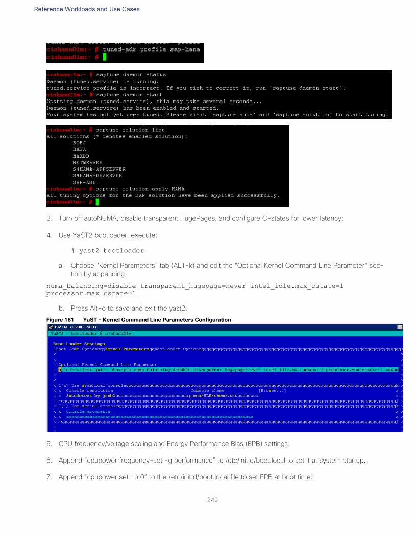
Reference Workloads and Use Cases
242
3. Turn off autoNUMA, disable transparent HugePages, and configure C-states for lower latency:
4. Use YaST2 bootloader, execute:
# yast2 bootloader
a. Choose "Kernel Parameters" tab (ALT-k) and edit the "Optional Kernel Command Line Parameter" sec-
tion by appending:
numa_balancing=disable transparent_hugepage=never intel_idle.max_cstate=1
processor.max_cstate=1
b. Press Alt+o to save and exit the yast2.
Figure 181 YaST – Kernel Command Line Parameters Configuration
5. CPU frequency/voltage scaling and Energy Performance Bias (EPB) settings:
6. Append “cpupower frequency-set -g performance” to /etc/init.d/boot.local to set it at system startup.
7. Append “cpupower set -b 0” to the /etc/init.d/boot.local file to set EPB at boot time:
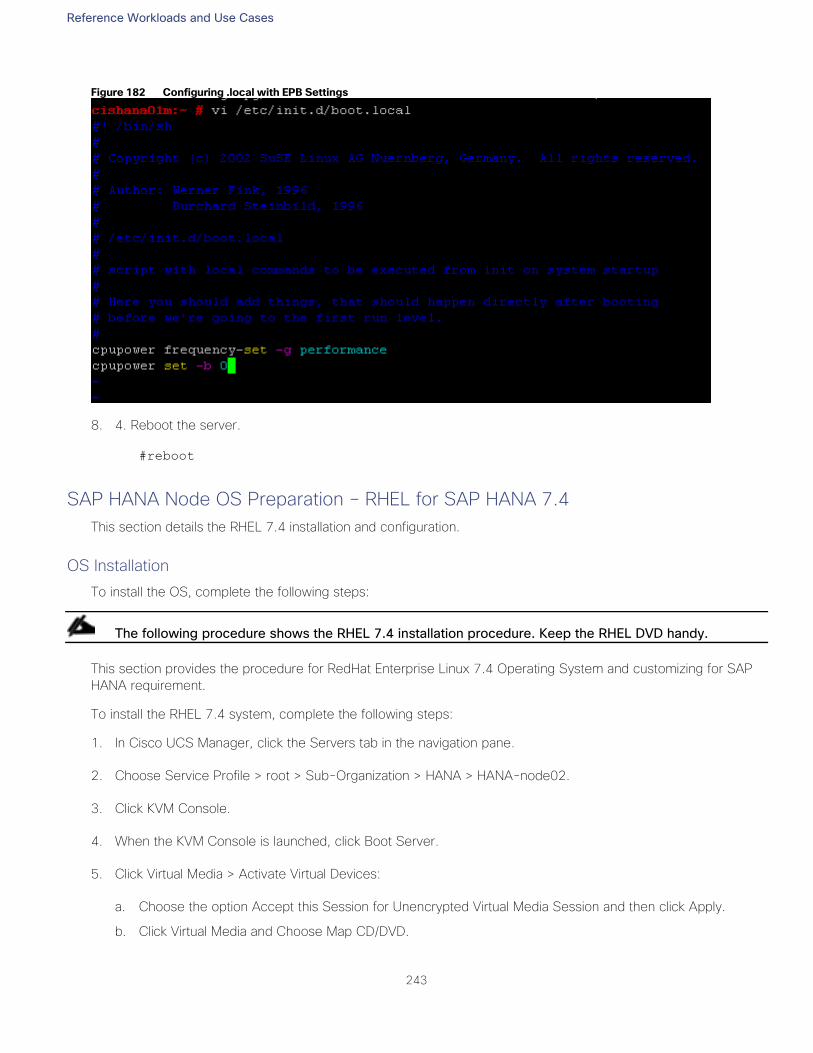
Reference Workloads and Use Cases
243
Figure 182 Configuring .local with EPB Settings
8. 4. Reboot the server.
#reboot
SAP HANA Node OS Preparation – RHEL for SAP HANA 7.4
This section details the RHEL 7.4 installation and configuration.
OS Installation
To install the OS, complete the following steps:
The following procedure shows the RHEL 7.4 installation procedure. Keep the RHEL DVD handy.
This section provides the procedure for RedHat Enterprise Linux 7.4 Operating System and customizing for SAP
HANA requirement.
To install the RHEL 7.4 system, complete the following steps:
1. In Cisco UCS Manager, click the Servers tab in the navigation pane.
2. Choose Service Profile > root > Sub-Organization > HANA > HANA-node02.
3. Click KVM Console.
4. When the KVM Console is launched, click Boot Server.
5. Click Virtual Media > Activate Virtual Devices:
a. Choose the option Accept this Session for Unencrypted Virtual Media Session and then click Apply.
b. Click Virtual Media and Choose Map CD/DVD.
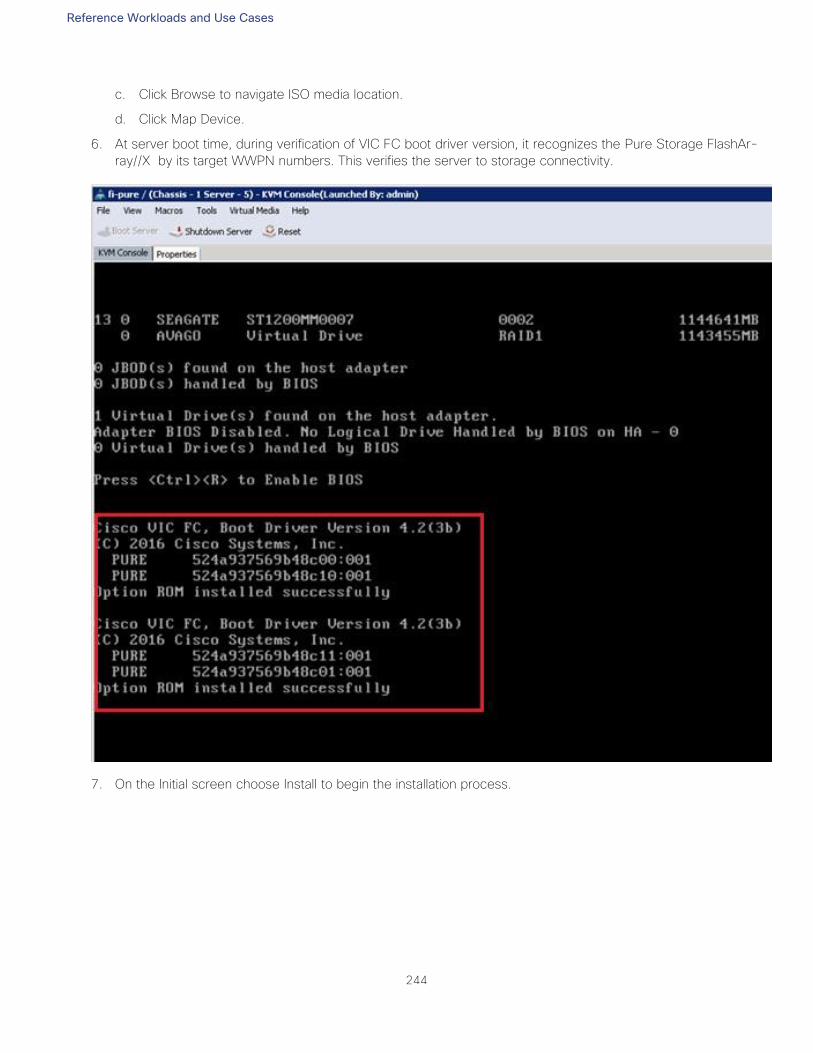
Reference Workloads and Use Cases
244
c. Click Browse to navigate ISO media location.
d. Click Map Device.
6. At server boot time, during verification of VIC FC boot driver version, it recognizes the Pure Storage FlashAr-
ray//X by its target WWPN numbers. This verifies the server to storage connectivity.
7. On the Initial screen choose Install to begin the installation process.
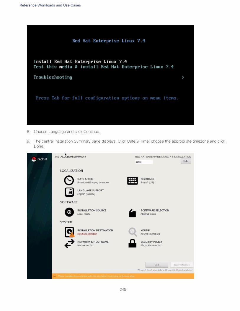
Reference Workloads and Use Cases
245
8. Choose Language and click Continue.
9. The central Installation Summary page displays. Click Date & Time; choose the appropriate timezone and click
Done.
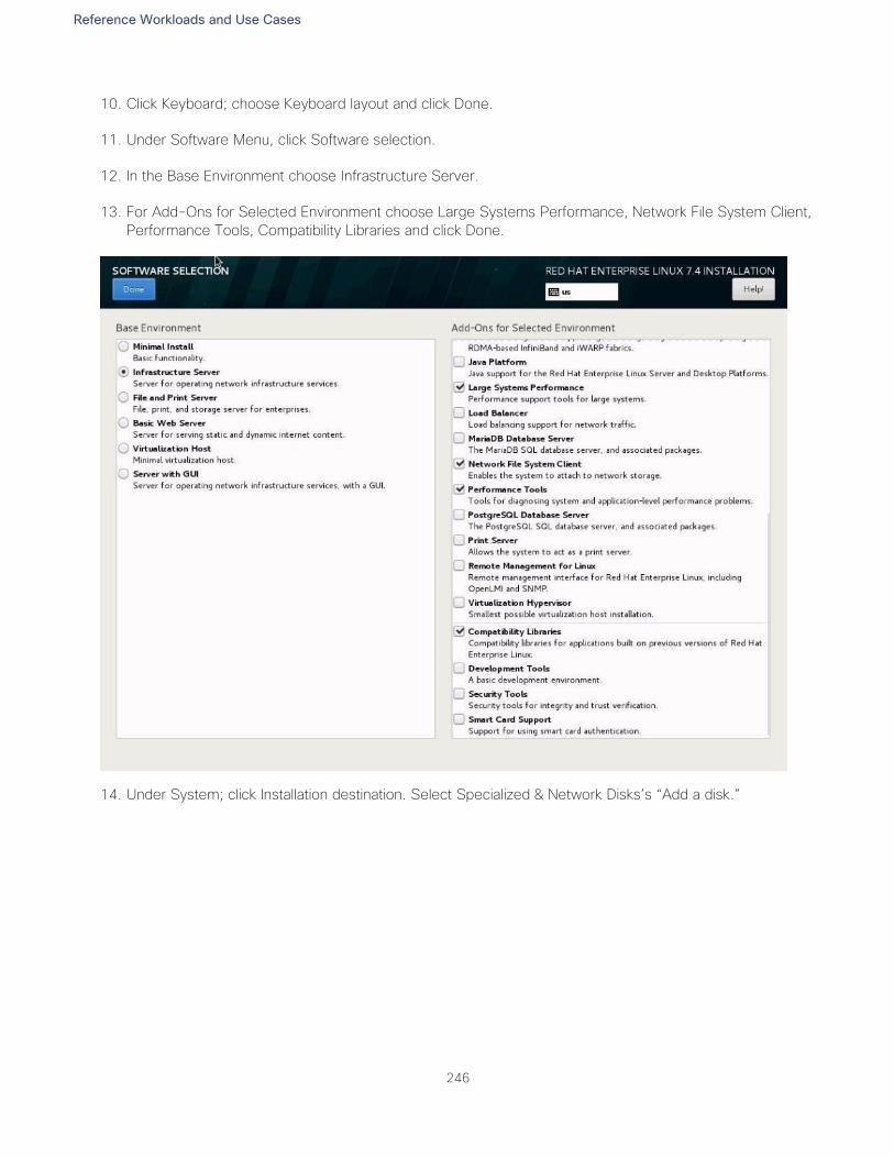
Reference Workloads and Use Cases
246
10. Click Keyboard; choose Keyboard layout and click Done.
11. Under Software Menu, click Software selection.
12. In the Base Environment choose Infrastructure Server.
13. For Add-Ons for Selected Environment choose Large Systems Performance, Network File System Client,
Performance Tools, Compatibility Libraries and click Done.
14. Under System; click Installation destination. Select Specialized & Network Disks’s “Add a disk.”
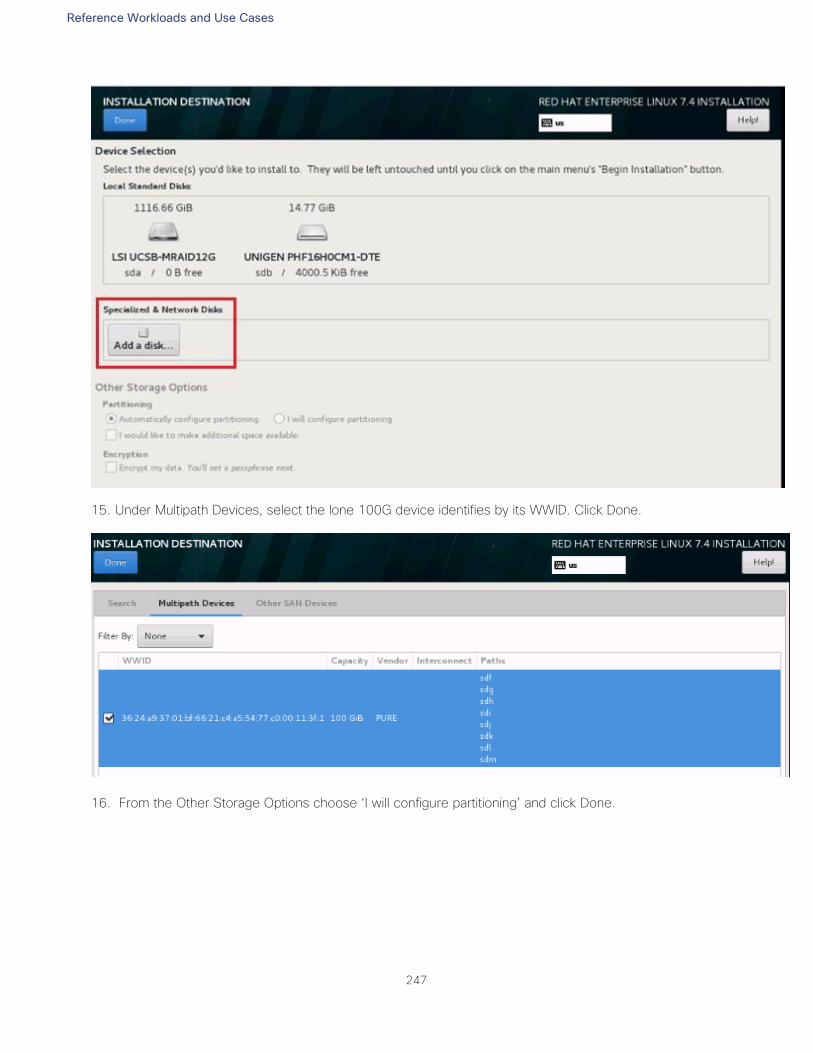
Reference Workloads and Use Cases
247
15. Under Multipath Devices, select the lone 100G device identifies by its WWID. Click Done.
16. From the Other Storage Options choose ‘I will configure partitioning’ and click Done.
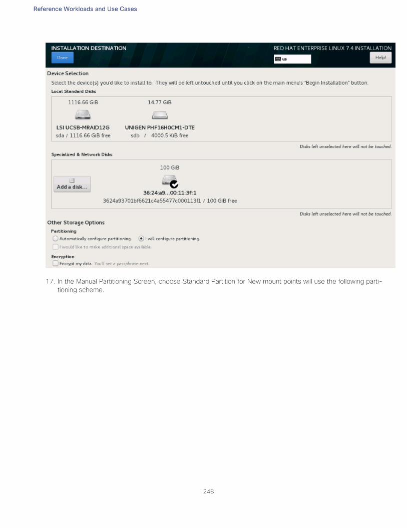
Reference Workloads and Use Cases
248
17. In the Manual Partitioning Screen, choose Standard Partition for New mount points will use the following parti-
tioning scheme.
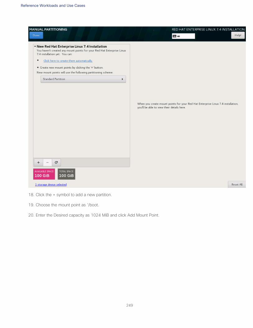
Reference Workloads and Use Cases
249
18. Click the + symbol to add a new partition.
19. Choose the mount point as ‘/boot.
20. Enter the Desired capacity as 1024 MiB and click Add Mount Point.
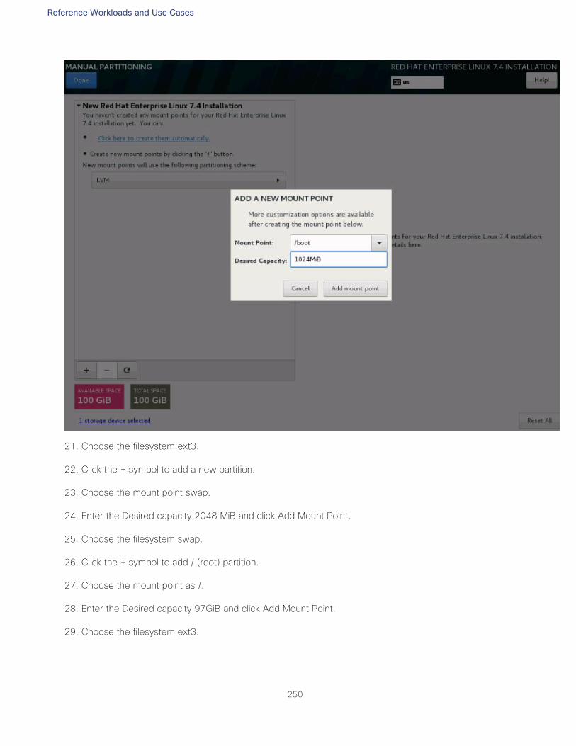
Reference Workloads and Use Cases
250
21. Choose the filesystem ext3.
22. Click the + symbol to add a new partition.
23. Choose the mount point swap.
24. Enter the Desired capacity 2048 MiB and click Add Mount Point.
25. Choose the filesystem swap.
26. Click the + symbol to add / (root) partition.
27. Choose the mount point as /.
28. Enter the Desired capacity 97GiB and click Add Mount Point.
29. Choose the filesystem ext3.
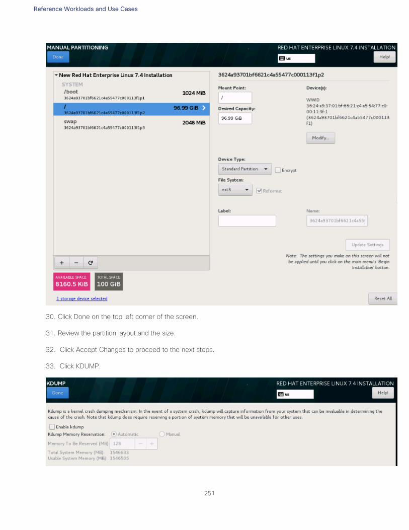
Reference Workloads and Use Cases
251
30. Click Done on the top left corner of the screen.
31. Review the partition layout and the size.
32. Click Accept Changes to proceed to the next steps.
33. Click KDUMP.
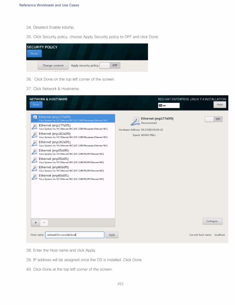
Reference Workloads and Use Cases
252
34. Deselect Enable kdump.
35. Click Security policy, choose Apply Security policy to OFF and click Done.
36. Click Done on the top left corner of the screen.
37. Click Network & Hostname.
38. Enter the Host name and click Apply.
39. IP address will be assigned once the OS is installed. Click Done.
40. Click Done at the top left corner of the screen.
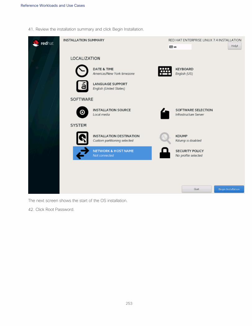
Reference Workloads and Use Cases
253
41. Review the installation summary and click Begin Installation.
The next screen shows the start of the OS installation.
42. Click Root Password.
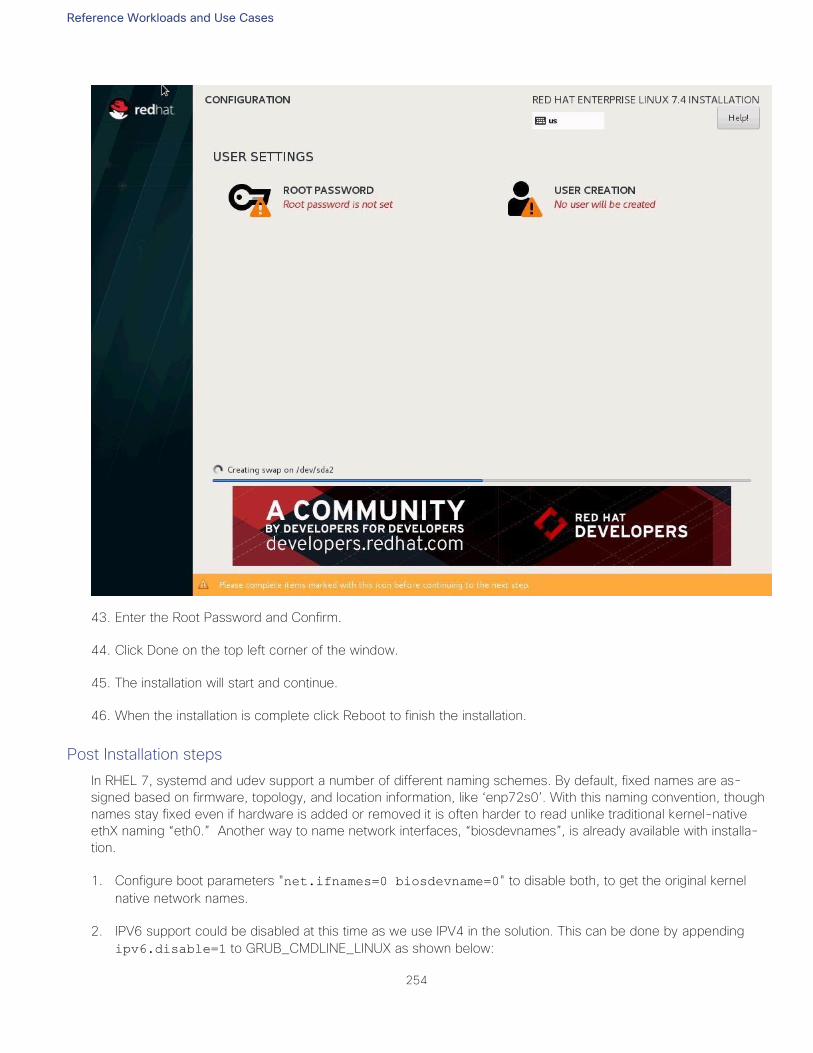
Reference Workloads and Use Cases
254
43. Enter the Root Password and Confirm.
44. Click Done on the top left corner of the window.
45. The installation will start and continue.
46. When the installation is complete click Reboot to finish the installation.
Post Installation steps
In RHEL 7, systemd and udev support a number of different naming schemes. By default, fixed names are as-
signed based on firmware, topology, and location information, like ‘enp72s0’. With this naming convention, though
names stay fixed even if hardware is added or removed it is often harder to read unlike traditional kernel-native
ethX naming “eth0.” Another way to name network interfaces, “biosdevnames”, is already available with installa-
tion.
1. Configure boot parameters "net.ifnames=0 biosdevname=0" to disable both, to get the original kernel
native network names.
2. IPV6 support could be disabled at this time as we use IPV4 in the solution. This can be done by appending
ipv6.disable=1 to GRUB_CMDLINE_LINUX as shown below:
Reference Workloads and Use Cases
255
cat /etc/default/grub
GRUB_TIMEOUT=5
GRUB_DISTRIBUTOR="$(sed 's, release .*$,,g' /etc/system-release)"
GRUB_DEFAULT=saved
GRUB_DISABLE_SUBMENU=true
GRUB_TERMINAL_OUTPUT="console"
GRUB_CMDLINE_LINUX="rhgb quiet net.ifnames=0 biosdevname=0 ipv6.disable=1"
GRUB_DISABLE_RECOVERY="true"
3. To Run the grub2-mkconfig command to regenerate the grub.cfg file:
grub2-mkconfig -o /boot/grub2/grub.cfg
4. Finally reboot system to effect the changes.
To configure the network interface on the OS, it is required to identify the mapping of the ethernet device on the
OS to vNIC interface on the Cisco UCS.
5. From the OS, execute the following command to get list of Ethernet device with MAC Address:
[root@cishanaso11 ~]# ip addr
1: lo: <LOOPBACK,UP,LOWER_UP> mtu 65536 qdisc noqueue state UNKNOWN qlen 1
link/loopback 00:00:00:00:00:00 brd 00:00:00:00:00:00
2: eth0: <BROADCAST,MULTICAST,UP,LOWER_UP> mtu 9000 qdisc mq state UP qlen 1000
link/ether 00:25:b5:00:0b:1e brd ff:ff:ff:ff:ff:ff
3: eth1: <BROADCAST,MULTICAST,UP,LOWER_UP> mtu 9000 qdisc mq state UP qlen 1000
link/ether 00:25:b5:00:0a:1f brd ff:ff:ff:ff:ff:ff
4: eth2: <BROADCAST,MULTICAST,UP,LOWER_UP> mtu 9000 qdisc mq state UP qlen 1000
link/ether 00:25:b5:00:0b:20 brd ff:ff:ff:ff:ff:ff
5: eth3: <BROADCAST,MULTICAST,UP,LOWER_UP> mtu 1500 qdisc mq state UP qlen 1000
link/ether 00:25:b5:00:0b:21 brd ff:ff:ff:ff:ff:ff
6: eth4: <BROADCAST,MULTICAST,UP,LOWER_UP> mtu 9000 qdisc mq state UP qlen 1000
link/ether 00:25:b5:00:0a:1e brd ff:ff:ff:ff:ff:ff
7: eth5: <BROADCAST,MULTICAST,UP,LOWER_UP> mtu 9000 qdisc mq state UP qlen 1000
link/ether 00:25:b5:00:0a:20 brd ff:ff:ff:ff:ff:ff
8: eth6: <BROADCAST,MULTICAST,UP,LOWER_UP> mtu 9000 qdisc mq state UP qlen 1000
link/ether 00:25:b5:00:0b:1f brd ff:ff:ff:ff:ff:ff
9: eth7: <BROADCAST,MULTICAST,UP,LOWER_UP> mtu 9000 qdisc mq state UP qlen 1000
link/ether 00:25:b5:00:0a:21 brd ff:ff:ff:ff:ff:ff
6. In Cisco UCS Manager, click the Servers tab in the navigation pane. Expand Servers > Service Profile > root >
Sub-Organization > HANA > HANA-node02. Click + to Expand. Click vNICs. On the right pane list of the
vNICs with MAC Address are listed.
Reference Workloads and Use Cases
256
Notice the MAC Address of the HANA-Internal vNIC is “00:25:B5:00:0B:21”. By comparing MAC Ad-
dress on the OS and Cisco UCS, we can derive that eth3 on OS will carry the VLAN for HANA-Mgmt. A
VLAN-ethernet-IPaddress mapping cheat sheet as below would help.
7. Go to network configuration directory and create a configuration for eth0:
cd /etc/sysconfig/network-scripts/
vi ifcfg-eth0
DEVICE=eth0
TYPE=Ethernet
ONBOOT=yes
BOOTPROTO=static
IPV6INIT=no
USERCTL=no
NM_CONTROLLED=no
IPADDR=<<IP address for HANA-Mgmt network example:192.168.76.201>>
NETMASK=<<subnet mask for HANA-Mgmt192.168 network 255.255.255.0>>
8. Derive and assign IP addresses for the rest of the interfaces.
9. Add default gateway:
vi /etc/sysconfig/network
NETWORKING=yes
HOSTNAME=<<HOSTNAME.DOMAIN>>
GATEWAY=<<IP Address of default gateway>>
10. Restart network to effect the IP address and gateway assignment.
systemctl restart network
Reference Workloads and Use Cases
257
11. Domain Name Service configuration must be done based on the local requirements.
12. Add DNS IP if it is required to access internet:
vi /etc/resolv.conf
DNS1=<<IP of DNS Server1>>
DNS2=<<IP of DNS Server2>>
DOMAIN= <<Domain_name>>
13. Update fnic and enic drivers:
Based on the serer type/model, processor version, OS release and version information download the Firware
bundle corresponding to the UCS Server firmware installed from the Cisco UCS Hardware and Software
Compatibility site
Extract the rpm files of the fnic and enic drivers from the bundle over to the node.
cishana02m:~ # rpm -Uvh <fnic.rpm>
cishana02m:~ # rpm -Uvh <enic.rpm>
14. Configure the udev rules:
The device manager of the kernel needs to be configured as shown below. Most important parameters to be
changed are nr_requests and scheduler. Please set parameters has shown below for Pure Storage in the
/etc/udev/rules.d directoy as shown below:
#cd /etc/udev/rules.d
#vi 99-pure-storage.rules
# Recommended settings for Pure Storage FlashArray.
# Use noop scheduler for high-performance solid-state storage
ACTION=="add|change", KERNEL=="sd*[!0-9]", SUBSYSTEM=="block",
ENV{ID_VENDOR}=="PURE", ATTR{queue/scheduler}="noop"
# Reduce CPU overhead due to entropy collection
ACTION=="add|change", KERNEL=="sd*[!0-9]", SUBSYSTEM=="block",
ENV{ID_VENDOR}=="PURE", ATTR{queue/add_random}="0"
# Spread CPU load by redirecting completions to originating CPU
ACTION=="add|change", KERNEL=="sd*[!0-9]", SUBSYSTEM=="block",
ENV{ID_VENDOR}=="PURE", ATTR{queue/rq_affinity}="2"
ACTION=="add|change", KERNEL=="sd*[!0-9]", SUBSYSTEM=="block",
ENV{ID_VENDOR}=="PURE", ATTR{queue/nr_requests}="1024"
ACTION=="add|change", KERNEL=="sd*[!0-9]", SUBSYSTEM=="block",
ENV{ID_VENDOR}=="PURE", ATTR{queue/nomerges}="1"
ACTION=="add|change", KERNEL=="sd*[!0-9]", SUBSYSTEM=="block",
ENV{ID_VENDOR}=="PURE", ATTR{queue/rotational}="0"
ACTION=="add|change", ENV{DM_UUID}=="mpath-3624a937?*",
ATTR{queue/scheduler}="noop"
ACTION=="add|change", ENV{DM_UUID}=="mpath-3624a937?*",
ATTR{queue/rotational}="0"
ACTION=="add|change", ENV{DM_UUID}=="mpath-3624a937?*",
ATTR{queue/nr_requests}="4096"
ACTION=="add|change", ENV{DM_UUID}=="mpath-3624a937?*",
ATTR{queue/rq_affinity}="2"
ACTION=="add|change", ENV{DM_UUID}=="mpath-3624a937?*",
ATTR{queue/nomerges}="1"
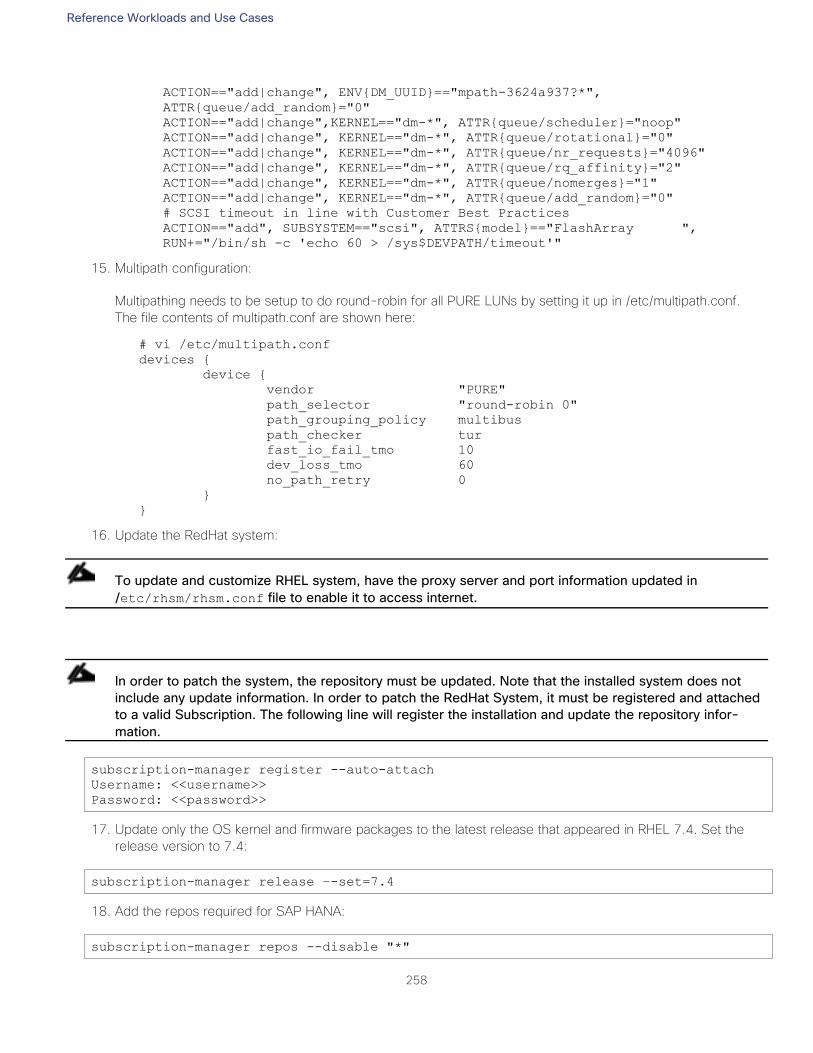
Reference Workloads and Use Cases
258
ACTION=="add|change", ENV{DM_UUID}=="mpath-3624a937?*",
ATTR{queue/add_random}="0"
ACTION=="add|change",KERNEL=="dm-*", ATTR{queue/scheduler}="noop"
ACTION=="add|change", KERNEL=="dm-*", ATTR{queue/rotational}="0"
ACTION=="add|change", KERNEL=="dm-*", ATTR{queue/nr_requests}="4096"
ACTION=="add|change", KERNEL=="dm-*", ATTR{queue/rq_affinity}="2"
ACTION=="add|change", KERNEL=="dm-*", ATTR{queue/nomerges}="1"
ACTION=="add|change", KERNEL=="dm-*", ATTR{queue/add_random}="0"
# SCSI timeout in line with Customer Best Practices
ACTION=="add", SUBSYSTEM=="scsi", ATTRS{model}=="FlashArray ",
RUN+="/bin/sh -c 'echo 60 > /sys$DEVPATH/timeout'"
15. Multipath configuration:
Multipathing needs to be setup to do round-robin for all PURE LUNs by setting it up in /etc/multipath.conf.
The file contents of multipath.conf are shown here:
# vi /etc/multipath.conf
devices {
device {
vendor "PURE"
path_selector "round-robin 0"
path_grouping_policy multibus
path_checker tur
fast_io_fail_tmo 10
dev_loss_tmo 60
no_path_retry 0
}
}
16. Update the RedHat system:
To update and customize RHEL system, have the proxy server and port information updated in
/etc/rhsm/rhsm.conf file to enable it to access internet.
In order to patch the system, the repository must be updated. Note that the installed system does not
include any update information. In order to patch the RedHat System, it must be registered and attached
to a valid Subscription. The following line will register the installation and update the repository infor-
mation.
subscription-manager register --auto-attach
Username: <<username>>
Password: <<password>>
17. Update only the OS kernel and firmware packages to the latest release that appeared in RHEL 7.4. Set the
release version to 7.4:
subscription-manager release –-set=7.4
18. Add the repos required for SAP HANA:
subscription-manager repos --disable "*"
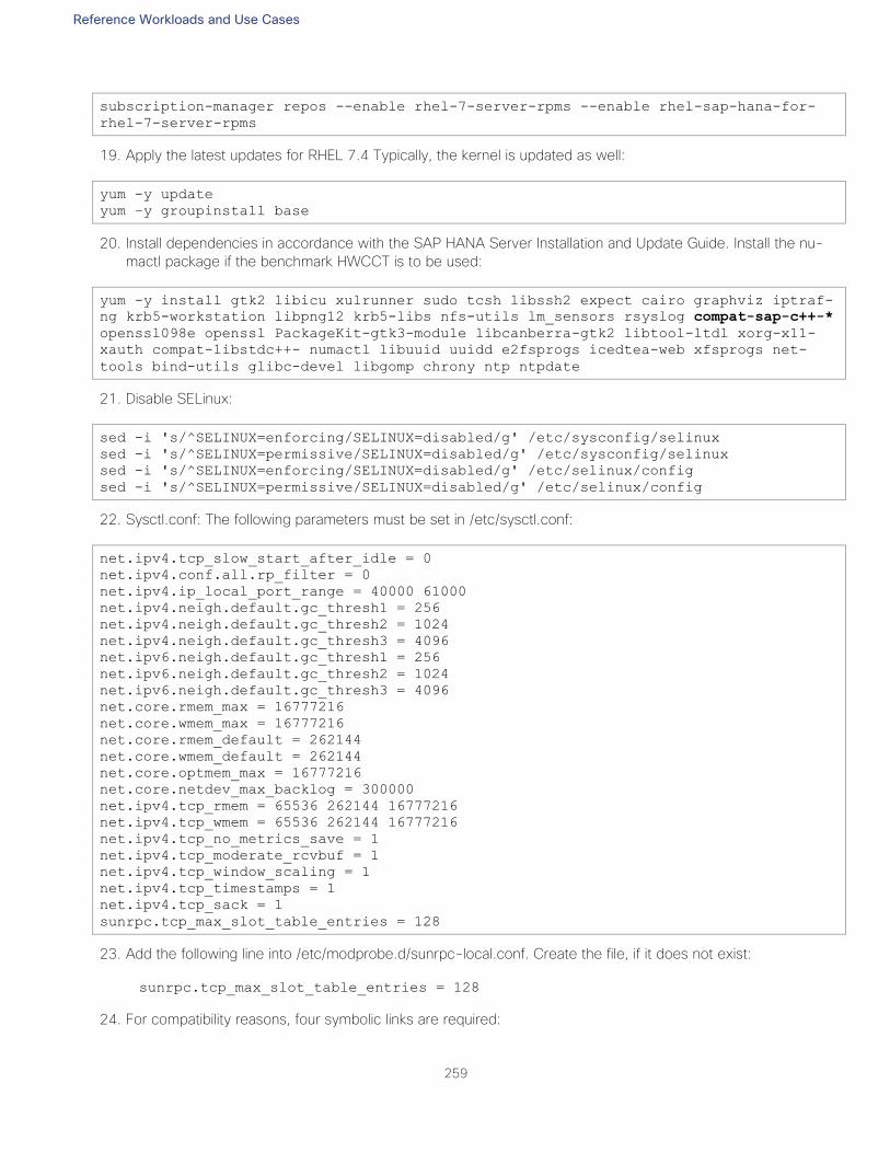
Reference Workloads and Use Cases
259
subscription-manager repos --enable rhel-7-server-rpms --enable rhel-sap-hana-for-
rhel-7-server-rpms
19. Apply the latest updates for RHEL 7.4 Typically, the kernel is updated as well:
yum -y update
yum –y groupinstall base
20. Install dependencies in accordance with the SAP HANA Server Installation and Update Guide. Install the nu-
mactl package if the benchmark HWCCT is to be used:
yum -y install gtk2 libicu xulrunner sudo tcsh libssh2 expect cairo graphviz iptraf-
ng krb5-workstation libpng12 krb5-libs nfs-utils lm_sensors rsyslog compat-sap-c++-*
openssl098e openssl PackageKit-gtk3-module libcanberra-gtk2 libtool-ltdl xorg-x11-
xauth compat-libstdc++- numactl libuuid uuidd e2fsprogs icedtea-web xfsprogs net-
tools bind-utils glibc-devel libgomp chrony ntp ntpdate
21. Disable SELinux:
sed -i 's/^SELINUX=enforcing/SELINUX=disabled/g' /etc/sysconfig/selinux
sed -i 's/^SELINUX=permissive/SELINUX=disabled/g' /etc/sysconfig/selinux
sed -i 's/^SELINUX=enforcing/SELINUX=disabled/g' /etc/selinux/config
sed -i 's/^SELINUX=permissive/SELINUX=disabled/g' /etc/selinux/config
22. Sysctl.conf: The following parameters must be set in /etc/sysctl.conf:
net.ipv4.tcp_slow_start_after_idle = 0
net.ipv4.conf.all.rp_filter = 0
net.ipv4.ip_local_port_range = 40000 61000
net.ipv4.neigh.default.gc_thresh1 = 256
net.ipv4.neigh.default.gc_thresh2 = 1024
net.ipv4.neigh.default.gc_thresh3 = 4096
net.ipv6.neigh.default.gc_thresh1 = 256
net.ipv6.neigh.default.gc_thresh2 = 1024
net.ipv6.neigh.default.gc_thresh3 = 4096
net.core.rmem_max = 16777216
net.core.wmem_max = 16777216
net.core.rmem_default = 262144
net.core.wmem_default = 262144
net.core.optmem_max = 16777216
net.core.netdev_max_backlog = 300000
net.ipv4.tcp_rmem = 65536 262144 16777216
net.ipv4.tcp_wmem = 65536 262144 16777216
net.ipv4.tcp_no_metrics_save = 1
net.ipv4.tcp_moderate_rcvbuf = 1
net.ipv4.tcp_window_scaling = 1
net.ipv4.tcp_timestamps = 1
net.ipv4.tcp_sack = 1
sunrpc.tcp_max_slot_table_entries = 128
23. Add the following line into /etc/modprobe.d/sunrpc-local.conf. Create the file, if it does not exist:
sunrpc.tcp_max_slot_table_entries = 128
24. For compatibility reasons, four symbolic links are required:
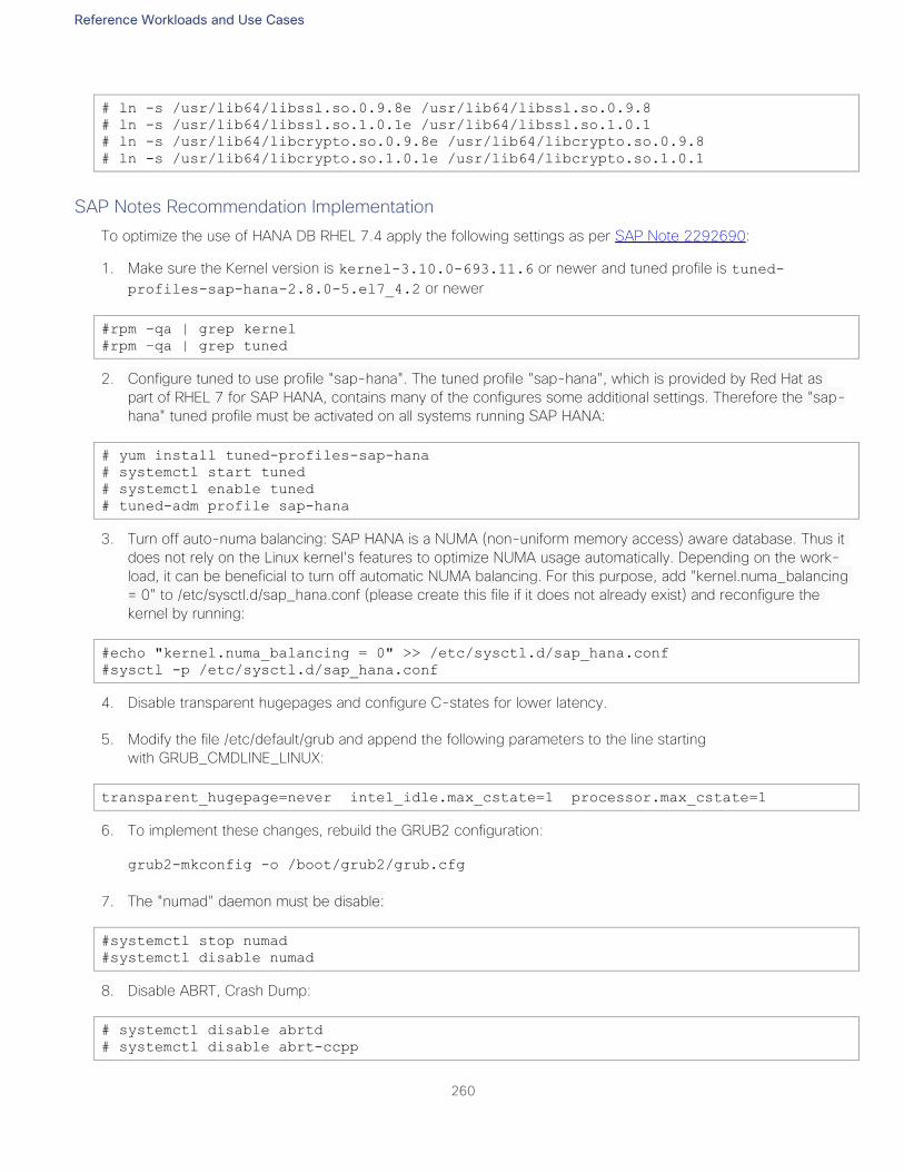
Reference Workloads and Use Cases
260
# ln -s /usr/lib64/libssl.so.0.9.8e /usr/lib64/libssl.so.0.9.8
# ln -s /usr/lib64/libssl.so.1.0.1e /usr/lib64/libssl.so.1.0.1
# ln -s /usr/lib64/libcrypto.so.0.9.8e /usr/lib64/libcrypto.so.0.9.8
# ln -s /usr/lib64/libcrypto.so.1.0.1e /usr/lib64/libcrypto.so.1.0.1
SAP Notes Recommendation Implementation
To optimize the use of HANA DB RHEL 7.4 apply the following settings as per SAP Note 2292690:
1. Make sure the Kernel version is kernel-3.10.0-693.11.6 or newer and tuned profile is tuned-
profiles-sap-hana-2.8.0-5.el7_4.2 or newer
#rpm –qa | grep kernel
#rpm –qa | grep tuned
2. Configure tuned to use profile "sap-hana". The tuned profile "sap-hana", which is provided by Red Hat as
part of RHEL 7 for SAP HANA, contains many of the configures some additional settings. Therefore the "sap-
hana" tuned profile must be activated on all systems running SAP HANA:
# yum install tuned-profiles-sap-hana
# systemctl start tuned
# systemctl enable tuned
# tuned-adm profile sap-hana
3. Turn off auto-numa balancing: SAP HANA is a NUMA (non-uniform memory access) aware database. Thus it
does not rely on the Linux kernel's features to optimize NUMA usage automatically. Depending on the work-
load, it can be beneficial to turn off automatic NUMA balancing. For this purpose, add "kernel.numa_balancing
= 0" to /etc/sysctl.d/sap_hana.conf (please create this file if it does not already exist) and reconfigure the
kernel by running:
#echo "kernel.numa_balancing = 0" >> /etc/sysctl.d/sap_hana.conf
#sysctl -p /etc/sysctl.d/sap_hana.conf
4. Disable transparent hugepages and configure C-states for lower latency.
5. Modify the file /etc/default/grub and append the following parameters to the line starting
with GRUB_CMDLINE_LINUX:
transparent_hugepage=never intel_idle.max_cstate=1 processor.max_cstate=1
6. To implement these changes, rebuild the GRUB2 configuration:
grub2-mkconfig -o /boot/grub2/grub.cfg
7. The "numad" daemon must be disable:
#systemctl stop numad
#systemctl disable numad
8. Disable ABRT, Crash Dump:
# systemctl disable abrtd
# systemctl disable abrt-ccpp
Reference Workloads and Use Cases
261
# systemctl stop abrtd
# systemctl stop abrt-ccpp
9. Disable core file creation. To disable core dumps for all users, open /etc/security/limits.conf, and add the line:
* soft core 0
* hard core 0
10. Enable group "sapsys" to create an unlimited number of processes:
echo "@sapsys soft nproc unlimited" > /etc/security/limits.d/99-sapsys.conf
11. Disable Firewall:
# systemctl stop firewalld
# systemctl disable firewalld
12. Reboot the OS by issuing reboot command.
13. Optional: old kernels can be removed after OS update:
package-cleanup --oldkernels --count=1 -y
System preparation for SAP HANA Scale-Up use-case
This is a common deployment methodology of SAP HANA on premise. The high-level steps for this use case are
as follows:
Create the Boot, Data, Log, and Shared Filesystem LUNs
Install and Configure the Operating System
Install SAP HANA
Test the connection to the SAP HANA database
Workload Definition
As an example, Customer XX wants to implement SAP HANA with a requirement of a single system to start with
and database growth not exceeding 1.5TB. Customer XX has the latest Skylake-based Cisco UCS B480 M5
servers and Pure Storage in his datacenter that he likes to leverage in a sharing mode. Since this is a TDI
implementation, Customer XX can repurpose the FlashStack gear he has, making sure that HANA HWCCT TDI
KPIs are met to receive SAP support.
Requirements
As a best practice, it is good to Scale-UP and then to Scale-Out based on the future growth requirements. For a
SAP HANA database in a Scale-Up configuration, the required networks are the access network and the storage
network. All other networks are optional.
Memory: 1.5 TB
CPU: 4x Intel Xeon Skylake CPUs 8176
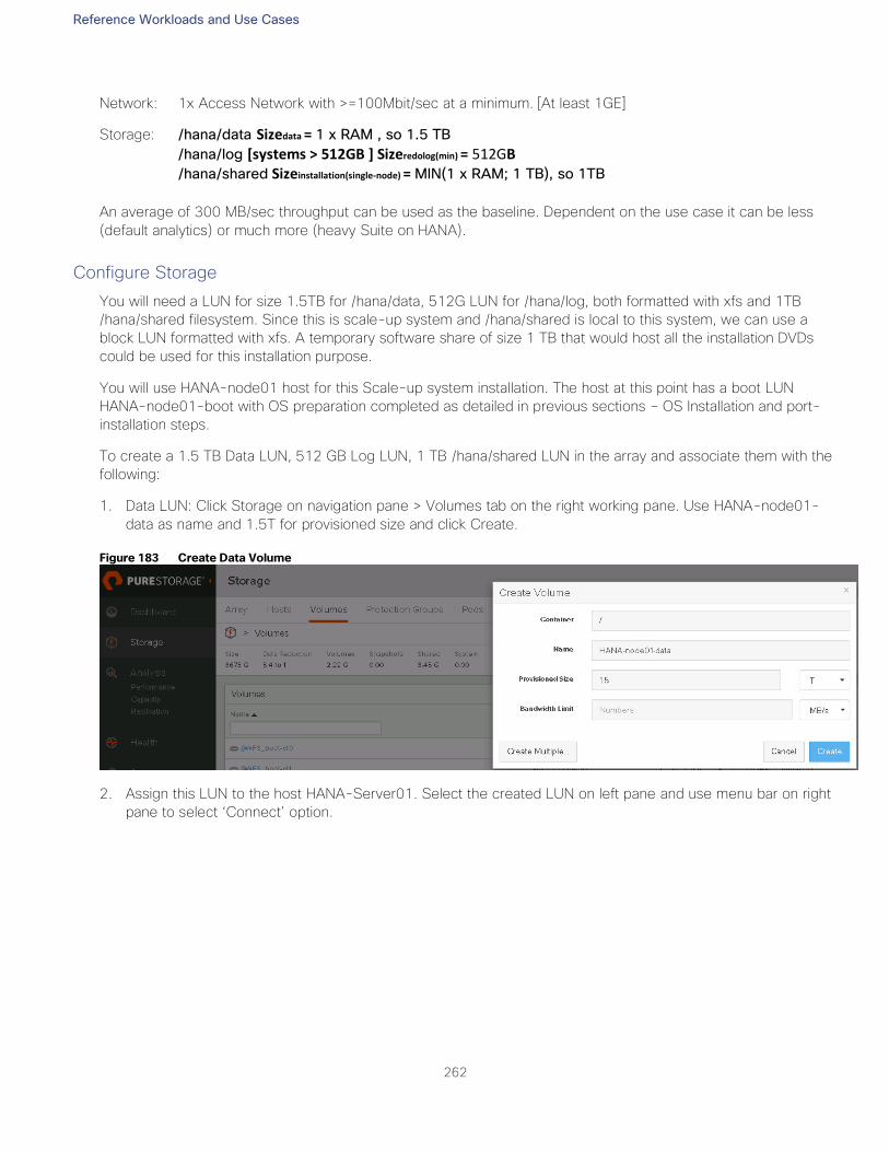
Reference Workloads and Use Cases
262
Network: 1x Access Network with >=100Mbit/sec at a minimum. [At least 1GE]
Storage: /hana/data Sizedata = 1 x RAM , so 1.5 TB
/hana/log [systems > 512GB ] Sizeredolog(min) = 512GB /hana/shared Sizeinstallation(single-node) = MIN(1 x RAM; 1 TB), so 1TB
An average of 300 MB/sec throughput can be used as the baseline. Dependent on the use case it can be less
(default analytics) or much more (heavy Suite on HANA).
Configure Storage
You will need a LUN for size 1.5TB for /hana/data, 512G LUN for /hana/log, both formatted with xfs and 1TB
/hana/shared filesystem. Since this is scale-up system and /hana/shared is local to this system, we can use a
block LUN formatted with xfs. A temporary software share of size 1 TB that would host all the installation DVDs
could be used for this installation purpose.
You will use HANA-node01 host for this Scale-up system installation. The host at this point has a boot LUN
HANA-node01-boot with OS preparation completed as detailed in previous sections – OS Installation and port-
installation steps.
To create a 1.5 TB Data LUN, 512 GB Log LUN, 1 TB /hana/shared LUN in the array and associate them with the
following:
1. Data LUN: Click Storage on navigation pane > Volumes tab on the right working pane. Use HANA-node01-
data as name and 1.5T for provisioned size and click Create.
Figure 183 Create Data Volume
2. Assign this LUN to the host HANA-Server01. Select the created LUN on left pane and use menu bar on right
pane to select ‘Connect’ option.
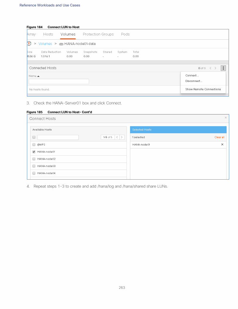
Reference Workloads and Use Cases
263
Figure 184 Connect LUN to Host
3. Check the HANA-Server01 box and click Connect.
Figure 185 Connect LUN to Host- Cont’d
4. Repeat steps 1-3 to create and add /hana/log and /hana/shared share LUNs.
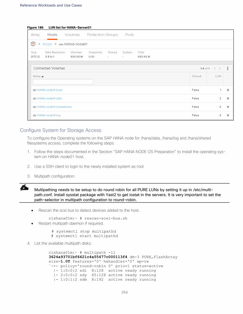
Reference Workloads and Use Cases
264
Figure 186 LUN list for HANA-Server01
Configure System for Storage Access
To configure the Operating systems on the SAP HANA node for /hana/data, /hana/log and /hana/shared
filesystems access, complete the following steps:
1. Follow the steps documented in the Section “SAP HANA NODE OS Preparation” to install the operating sys-
tem on HANA-node01 host.
2. Use a SSH client to login to the newly installed system as root
3. Multipath configuration:
Multipathing needs to be setup to do round robin for all PURE LUNs by setting it up in /etc/multi-
path.conf. Install sysstat package with Yast2 to get iostat in the servers. It is very important to set the
path-selector in multipath configuration to round-robin.
Rescan the scsi bus to detect devices added to the host.
cishana01m:~ # rescan-scsi-bus.sh
Restart multipath daemon if required.
# systemctl stop multipathd
# systemctl start multipathd
4. List the available multipath disks:
cishana01m:~ # multipath -ll
3624a93701bf6621c4a55477c000113f4 dm-3 PURE,FlashArray
size=1.0T features='0' hwhandler='0' wp=rw
`-+- policy='round-robin 0' prio=1 status=active
|- 1:0:0:2 sdi 8:128 active ready running
|- 2:0:0:2 sdy 65:128 active ready running
|- 1:0:1:2 sdm 8:192 active ready running
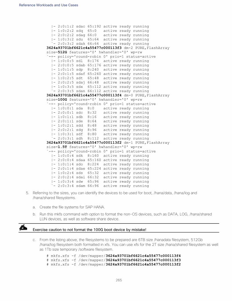
Reference Workloads and Use Cases
265
|- 2:0:1:2 sdac 65:192 active ready running
|- 1:0:2:2 sdq 65:0 active ready running
|- 2:0:2:2 sdag 66:0 active ready running
|- 1:0:3:2 sdu 65:64 active ready running
`- 2:0:3:2 sdak 66:64 active ready running
3624a93701bf6621c4a55477c000113f3 dm-2 PURE,FlashArray
size=512G features='0' hwhandler='0' wp=rw
`-+- policy='round-robin 0' prio=1 status=active
|- 1:0:0:5 sdl 8:176 active ready running
|- 2:0:0:5 sdab 65:176 active ready running
|- 1:0:1:5 sdp 8:240 active ready running
|- 2:0:1:5 sdaf 65:240 active ready running
|- 1:0:2:5 sdt 65:48 active ready running
|- 2:0:2:5 sdaj 66:48 active ready running
|- 1:0:3:5 sdx 65:112 active ready running
`- 2:0:3:5 sdan 66:112 active ready running
3624a93701bf6621c4a55477c000113f4 dm-0 PURE,FlashArray
size=100G features='0' hwhandler='0' wp=rw
`-+- policy='round-robin 0' prio=1 status=active
|- 1:0:0:1 sda 8:0 active ready running
|- 2:0:0:1 sdc 8:32 active ready running
|- 1:0:1:1 sdb 8:16 active ready running
|- 2:0:1:1 sde 8:64 active ready running
|- 1:0:2:1 sdd 8:48 active ready running
|- 2:0:2:1 sdg 8:96 active ready running
|- 1:0:3:1 sdf 8:80 active ready running
`- 2:0:3:1 sdh 8:112 active ready running
3624a93701bf6621c4a55477c000113f2 dm-1 PURE,FlashArray
size=1.5T features='0' hwhandler='0' wp=rw
`-+- policy='round-robin 0' prio=1 status=active
|- 1:0:0:4 sdk 8:160 active ready running
|- 2:0:0:4 sdaa 65:160 active ready running
|- 1:0:1:4 sdo 8:224 active ready running
|- 2:0:1:4 sdae 65:224 active ready running
|- 1:0:2:4 sds 65:32 active ready running
|- 2:0:2:4 sdai 66:32 active ready running
|- 1:0:3:4 sdw 65:96 active ready running
`- 2:0:3:4 sdam 66:96 active ready running
5. Referring to the sizes, you can identify the devices to be used for boot, /hana/data, /hana/log and
/hana/shared filesystems.
a. Create the file systems for SAP HANA.
b. Run this mkfs command with option to format the non-OS devices, such as DATA, LOG, /hana/shared
LUN devices, as well as software share device.
Exercise caution to not format the 100G boot device by mistake!
c. From the listing above, the filesystems to be prepared are 6TB size /hanadata filesystem, 512Gb
/hana/log filesystem both formatted in xfs. You can use xfs for the 2T size /hana/shared filesystem as well
as 1Tb size temporary /software filesystem.
# mkfs.xfs -f /dev/mapper/3624a93701bf6621c4a55477c000113f4
# mkfs.xfs -f /dev/mapper/3624a93701bf6621c4a55477c000113f3
# mkfs.xfs -f /dev/mapper/3624a93701bf6621c4a55477c000113f2
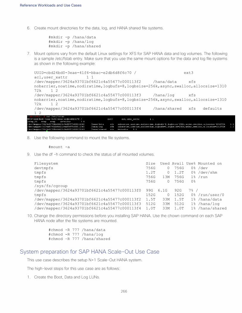
Reference Workloads and Use Cases
266
6. Create mount directories for the data, log, and HANA shared file systems.
#mkdir -p /hana/data
#mkdir -p /hana/log
#mkdir -p /hana/shared
7. Mount options vary from the default Linux settings for XFS for SAP HANA data and log volumes. The following
is a sample /etc/fstab entry. Make sure that you use the same mount options for the data and log file systems
as shown in the following example:
UUID=cbd24bd0-3eae-41f6-bbac-e2db6d8f6c70 / ext3
acl,user_xattr 1 1
/dev/mapper/3624a93701bf6621c4a55477c000113f2 /hana/data xfs
nobarrier,noatime,nodiratime,logbufs=8,logbsize=256k,async,swalloc,allocsize=1310
72k 1 2
/dev/mapper/3624a93701bf6621c4a55477c000113f3 /hana/log xfs
nobarrier,noatime,nodiratime,logbufs=8,logbsize=256k,async,swalloc,allocsize=1310
72k 1 2
/dev/mapper/3624a93701bf6621c4a55477c000113f4 /hana/shared xfs defaults
1 2
8. Use the following command to mount the file systems.
#mount -a
9. Use the df –h command to check the status of all mounted volumes.
Filesystem Size Used Avail Use% Mounted on
devtmpfs 756G 0 756G 0% /dev
tmpfs 1.2T 0 1.2T 0% /dev/shm
tmpfs 756G 13M 756G 1% /run
tmpfs 756G 0 756G 0%
/sys/fs/cgroup
/dev/mapper/3624a93701bf6621c4a55477c000113f0 99G 6.1G 92G 7% /
tmpfs 152G 0 152G 0% /run/user/0
/dev/mapper/3624a93701bf6621c4a55477c000113f2 1.5T 33M 1.5T 1% /hana/data
/dev/mapper/3624a93701bf6621c4a55477c000113f3 512G 33M 512G 1% /hana/log
/dev/mapper/3624a93701bf6621c4a55477c000113f4 1.0T 33M 1.0T 1% /hana/shared
10. Change the directory permissions before you installing SAP HANA. Use the chown command on each SAP
HANA node after the file systems are mounted.
#chmod -R 777 /hana/data
#chmod -R 777 /hana/log
#chmod –R 777 /hana/shared
System preparation for SAP HANA Scale-Out Use Case
This use case describes the setup N+1 Scale-Out HANA system.
The high-level steps for this use case are as follows:
1. Create the Boot, Data and Log LUNs.
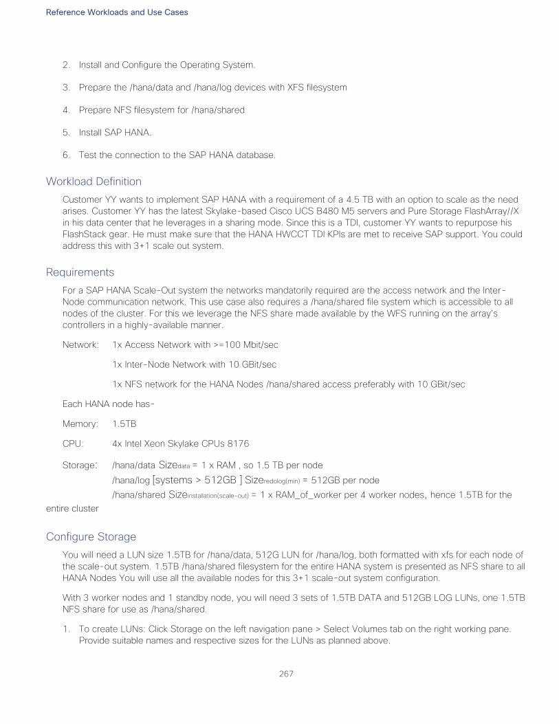
Reference Workloads and Use Cases
267
2. Install and Configure the Operating System.
3. Prepare the /hana/data and /hana/log devices with XFS filesystem
4. Prepare NFS filesystem for /hana/shared
5. Install SAP HANA.
6. Test the connection to the SAP HANA database.
Workload Definition
Customer YY wants to implement SAP HANA with a requirement of a 4.5 TB with an option to scale as the need
arises. Customer YY has the latest Skylake-based Cisco UCS B480 M5 servers and Pure Storage FlashArray//X
in his data center that he leverages in a sharing mode. Since this is a TDI, customer YY wants to repurpose his
FlashStack gear. He must make sure that the HANA HWCCT TDI KPIs are met to receive SAP support. You could
address this with 3+1 scale out system.
Requirements
For a SAP HANA Scale-Out system the networks mandatorily required are the access network and the Inter-
Node communication network. This use case also requires a /hana/shared file system which is accessible to all
nodes of the cluster. For this we leverage the NFS share made available by the WFS running on the array’s
controllers in a highly-available manner.
Network: 1x Access Network with >=100 Mbit/sec
1x Inter-Node Network with 10 GBit/sec
1x NFS network for the HANA Nodes /hana/shared access preferably with 10 GBit/sec
Each HANA node has-
Memory: 1.5TB
CPU: 4x Intel Xeon Skylake CPUs 8176
Storage: /hana/data Sizedata = 1 x RAM , so 1.5 TB per node
/hana/log [systems > 512GB ] Sizeredolog(min) = 512GB per node
/hana/shared Sizeinstallation(scale-out) = 1 x RAM_of_worker per 4 worker nodes, hence 1.5TB for the
entire cluster
Configure Storage
You will need a LUN size 1.5TB for /hana/data, 512G LUN for /hana/log, both formatted with xfs for each node of
the scale-out system. 1.5TB /hana/shared filesystem for the entire HANA system is presented as NFS share to all
HANA Nodes You will use all the available nodes for this 3+1 scale-out system configuration.
With 3 worker nodes and 1 standby node, you will need 3 sets of 1.5TB DATA and 512GB LOG LUNs, one 1.5TB
NFS share for use as /hana/shared.
1. To create LUNs: Click Storage on the left navigation pane > Select Volumes tab on the right working pane.
Provide suitable names and respective sizes for the LUNs as planned above.
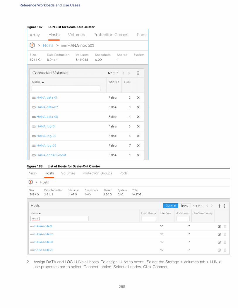
Reference Workloads and Use Cases
268
Figure 187 LUN List for Scale-Out Cluster
Figure 188 List of Hosts for Scale-Out Cluster
2. Assign DATA and LOG LUNs all hosts. To assign LUNs to hosts: Select the Storage > Volumes tab > LUN >
use properties bar to select ‘Connect’ option. Select all nodes. Click Connect.
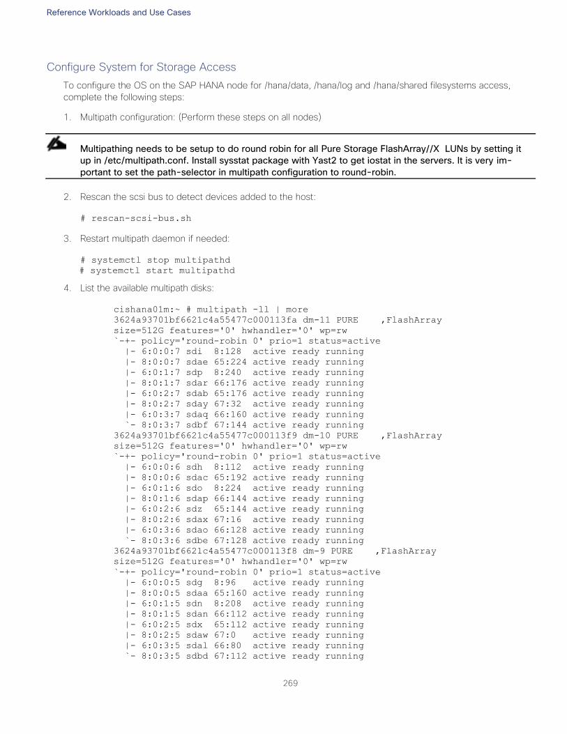
Reference Workloads and Use Cases
269
Configure System for Storage Access
To configure the OS on the SAP HANA node for /hana/data, /hana/log and /hana/shared filesystems access,
complete the following steps:
1. Multipath configuration: (Perform these steps on all nodes)
Multipathing needs to be setup to do round robin for all Pure Storage FlashArray//X LUNs by setting it
up in /etc/multipath.conf. Install sysstat package with Yast2 to get iostat in the servers. It is very im-
portant to set the path-selector in multipath configuration to round-robin.
2. Rescan the scsi bus to detect devices added to the host:
# rescan-scsi-bus.sh
3. Restart multipath daemon if needed:
# systemctl stop multipathd
# systemctl start multipathd
4. List the available multipath disks:
cishana01m:~ # multipath -ll | more
3624a93701bf6621c4a55477c000113fa dm-11 PURE ,FlashArray
size=512G features='0' hwhandler='0' wp=rw
`-+- policy='round-robin 0' prio=1 status=active
|- 6:0:0:7 sdi 8:128 active ready running
|- 8:0:0:7 sdae 65:224 active ready running
|- 6:0:1:7 sdp 8:240 active ready running
|- 8:0:1:7 sdar 66:176 active ready running
|- 6:0:2:7 sdab 65:176 active ready running
|- 8:0:2:7 sday 67:32 active ready running
|- 6:0:3:7 sdaq 66:160 active ready running
`- 8:0:3:7 sdbf 67:144 active ready running
3624a93701bf6621c4a55477c000113f9 dm-10 PURE ,FlashArray
size=512G features='0' hwhandler='0' wp=rw
`-+- policy='round-robin 0' prio=1 status=active
|- 6:0:0:6 sdh 8:112 active ready running
|- 8:0:0:6 sdac 65:192 active ready running
|- 6:0:1:6 sdo 8:224 active ready running
|- 8:0:1:6 sdap 66:144 active ready running
|- 6:0:2:6 sdz 65:144 active ready running
|- 8:0:2:6 sdax 67:16 active ready running
|- 6:0:3:6 sdao 66:128 active ready running
`- 8:0:3:6 sdbe 67:128 active ready running
3624a93701bf6621c4a55477c000113f8 dm-9 PURE ,FlashArray
size=512G features='0' hwhandler='0' wp=rw
`-+- policy='round-robin 0' prio=1 status=active
|- 6:0:0:5 sdg 8:96 active ready running
|- 8:0:0:5 sdaa 65:160 active ready running
|- 6:0:1:5 sdn 8:208 active ready running
|- 8:0:1:5 sdan 66:112 active ready running
|- 6:0:2:5 sdx 65:112 active ready running
|- 8:0:2:5 sdaw 67:0 active ready running
|- 6:0:3:5 sdal 66:80 active ready running
`- 8:0:3:5 sdbd 67:112 active ready running
Reference Workloads and Use Cases
270
3624a93701bf6621c4a55477c000113f7 dm-8 PURE ,FlashArray
size=1.5T features='0' hwhandler='0' wp=rw
`-+- policy='round-robin 0' prio=1 status=active
|- 6:0:0:4 sdf 8:80 active ready running
|- 8:0:0:4 sdy 65:128 active ready running
|- 6:0:1:4 sdm 8:192 active ready running
|- 8:0:1:4 sdam 66:96 active ready running
|- 6:0:2:4 sdu 65:64 active ready running
|- 8:0:2:4 sdav 66:240 active ready running
|- 6:0:3:4 sdaj 66:48 active ready running
`- 8:0:3:4 sdbc 67:96 active ready running
3624a93701bf6621c4a55477c000113f6 dm-7 PURE ,FlashArray
size=1.5T features='0' hwhandler='0' wp=rw
`-+- policy='round-robin 0' prio=1 status=active
|- 6:0:0:3 sde 8:64 active ready running
|- 8:0:0:3 sdw 65:96 active ready running
|- 6:0:1:3 sdl 8:176 active ready running
|- 8:0:1:3 sdak 66:64 active ready running
|- 6:0:2:3 sdt 65:48 active ready running
|- 8:0:2:3 sdau 66:224 active ready running
|- 6:0:3:3 sdah 66:16 active ready running
`- 8:0:3:3 sdbb 67:80 active ready running
3624a93701bf6621c4a55477c000113f5 dm-6 PURE ,FlashArray
size=1.5T features='0' hwhandler='0' wp=rw
`-+- policy='round-robin 0' prio=1 status=active
|- 6:0:0:2 sdd 8:48 active ready running
|- 8:0:0:2 sdv 65:80 active ready running
|- 6:0:1:2 sdk 8:160 active ready running
|- 8:0:1:2 sdai 66:32 active ready running
|- 6:0:2:2 sdr 65:16 active ready running
|- 8:0:2:2 sdat 66:208 active ready running
|- 6:0:3:2 sdaf 65:240 active ready running
`- 8:0:3:2 sdba 67:64 active ready running
3624a93701bf6621c4a55477c000113f1 dm-0 PURE ,FlashArray
size=100G features='0' hwhandler='0' wp=rw
`-+- policy='round-robin 0' prio=1 status=active
|- 6:0:0:1 sdc 8:32 active ready running
|- 8:0:0:1 sds 65:32 active ready running
|- 6:0:1:1 sdj 8:144 active ready running
|- 8:0:1:1 sdag 66:0 active ready running
|- 6:0:2:1 sdq 65:0 active ready running
|- 8:0:2:1 sdas 66:192 active ready running
|- 6:0:3:1 sdad 65:208 active ready running
`- 8:0:3:1 sdaz 67:48 active ready running
5. Referring to the sizes you can identify the devices to be used for /hana/data and /hana/log devices..
6. Create the file systems for SAP HANA [Step to be performed on one of the modes in the cluster only].
7. Run this mkfs command with option to format the non-OS devices, such as DATA, and LOG LUN devices as
well as software share device.
Exercise caution to not format the 100G boot device by mistake!
Reference Workloads and Use Cases
271
8. From the listing above, the filesystems to be prepared are 1.5TB size /hanadata filesystem, 512GB /hana/log
filesystem both formatted in xfs.
# mkfs.xfs -f /dev/mapper/3624a93701bf6621c4a55477c000113fa
# mkfs.xfs -f /dev/mapper/3624a93701bf6621c4a55477c000113f9
# mkfs.xfs -f /dev/mapper/3624a93701bf6621c4a55477c000113f8
# mkfs.xfs -f /dev/mapper/3624a93701bf6621c4a55477c000113f7
# mkfs.xfs -f /dev/mapper/3624a93701bf6621c4a55477c000113f6
# mkfs.xfs -f /dev/mapper/3624a93701bf6621c4a55477c000113f5
9. Create mount directories for the data, log, and HANA shared file systems on all nodes:
#mkdir -p /hana/data/<SID>
#cd /hana/data/<SID>
#mkdir mnt00001 mnt00002 mnt00003
#mkdir -p /hana/log/<SID>
#cd /hana/log/<SID>
#mkdir mnt00001 mnt00002 mnt00003
#mkdir -p /hana/shared
10. Change the directory permissions on all nodes before you installing SAP HANA. Use the chown command on
each SAP HANA node after the file systems are mounted.
#chmod -R 777 /hana/data
#chmod -R 777 /hana/log
#chmod –R 777 /hana/shared
11. Mount options vary from the default Linux settings for XFS for SAP HANA data and log volumes and NFS for
/hana/shared. The following is a sample /etc/fstab entry. Make sure that you use the same mount options for
the data, log and /hana/shared file systems as shown in the following example:
UUID=cbd24bd0-3eae-41f6-bbac-e2db6d8f6c70 / ext3
acl,user_xattr 1 1
/ /dev/mapper/3624a93701bf6621c4a55477c000113f5 /hana/data/ANA/mnt00001 xfs
nobarrier,noatime,nodiratime,logbufs=8,logbsize=256k,async,swalloc,allocsiz
e=131072k 1 2
/dev/mapper/3624a93701bf6621c4a55477c000113f8 /hana/log/ANA/mnt00001 xfs
nobarrier,noatime,nodiratime,logbufs=8,logbsize=256k,async,swalloc,allocsiz
e=131072k 1 2
/dev/mapper/3624a93701bf6621c4a55477c000113f6 /hana/data/ANA/mnt00002 xfs
nobarrier,noatime,nodiratime,logbufs=8,logbsize=256k,async,swalloc,allocsiz
e=131072k 1 2
/dev/mapper/3624a93701bf6621c4a55477c000113f9 /hana/log/ANA/mnt00002 xfs
nobarrier,noatime,nodiratime,logbufs=8,logbsize=256k,async,swalloc,allocsiz
e=131072k 1 2
/dev/mapper/3624a93701bf6621c4a55477c000113f7 /hana/data/ANA/mnt00003 xfs
nobarrier,noatime,nodiratime,logbufs=8,logbsize=256k,async,swalloc,allocsiz
e=131072k 1 2
Reference Workloads and Use Cases
272
/dev/mapper/3624a93701bf6621c4a55477c000113fa /hana/log/ANA/mnt00003 xfs
nobarrier,noatime,nodiratime,logbufs=8,logbsize=256k,async,swalloc,allocsiz
e=131072k 1 2
192.168.111.25:/hana-fs /hana/shared nfs4
rw,relatime,vers=4.1,rsize=1048576,wsize=1048576,namlen=255,hard,proto=tcp,port=0
,timeo=600,retrans=2,sec=sys,local_lock=none 0 0
We created the 1 TB size NFS share hana-fs for /hana/shared filesystem earlier and using the mount in-
formation here to update the /etc/fstab above.
12. Use the following command to mount the file systems:
#mount -a
13. Use the df –h command to check the status of all mounted volumes:
[root@cishana01m ~]# df -h
Filesystem Size Used Avail Use% Mounted on
/dev/mapper/3624a93701bf6621c4a55477c000113f1p2 96G 1.8G 89G 2% /
devtmpfs 756G 0 756G 0% /dev
tmpfs 756G 0 756G 0% /dev/shm
tmpfs 756G 11M 756G 1% /run
tmpfs 756G 0 756G 0%
/sys/fs/cgroup
/dev/mapper/3624a93701bf6621c4a55477c000113f1p1 976M 101M 824M 11% /boot
tmpfs 152G 0 152G 0%
/run/user/0
192.168.111.25:/hanashared 1.0T 227M 1.0T 1%
/hana/shared
/dev/mapper/3624a93701bf6621c4a55477c000113f5 1.5T 33M 1.5T 1%
/hana/data/ANA/mnt00001
/dev/mapper/3624a93701bf6621c4a55477c000113f8 512G 33M 512G 1%
/hana/log/ANA/mnt00001
/dev/mapper/3624a93701bf6621c4a55477c000113f6 1.5T 33M 1.5T 1%
/hana/data/ANA/mnt00002
/dev/mapper/3624a93701bf6621c4a55477c000113f9 512G 33M 512G 1%
/hana/log/ANA/mnt00002
/dev/mapper/3624a93701bf6621c4a55477c000113f7 1.5T 33M 1.5T 1%
/hana/data/ANA/mnt00003
/dev/mapper/3624a93701bf6621c4a55477c000113fa 512G 33M 512G 1%
/hana/log/ANA/mnt00003
[root@cishana02m ~]#
14. Enter the required information into the hosts file:
a. Update the /etc/hosts file of all nodes with the IP addresses of different networks assigned to the hosts’
interfaces.
vi /etc/hosts
127.0.0.1 localhost
# special IPv6 addresses
::1 localhost ipv6-localhost ipv6-loopback
fe00::0 ipv6-localnet
ff00::0 ipv6-mcastprefix
ff02::1 ipv6-allnodes
Reference Workloads and Use Cases
273
ff02::2 ipv6-allrouters
ff02::3 ipv6-allhosts
192.168.76.12 linux-jumpbox
#
## Internal Network
#
192.168.220.201 cishana01.ciscolab.local cishana01
192.168.220.202 cishana02.ciscolab.local cishana02
192.168.220.203 cishana03.ciscolab.local cishana03
192.168.220.204 cishana04.ciscolab.local cishana04
#
## NFS-shared Network
#
192.168.111.201 cishana01s.ciscolab.local cishana01s
192.168.111.202 cishana02s.ciscolab.local cishana02s
192.168.111.203 cishana03s.ciscolab.local cishana03s
192.168.111.204 cishana04s.ciscolab.local cishana04s
#
## Client Network
#
192.168.222.201 cishana01c.ciscolab.local cishana01c
192.168.222.202 cishana02c.ciscolab.local cishana02c
192.168.222.203 cishana03c.ciscolab.local cishana03c
192.168.222.204 cishana04c.ciscolab.local cishana04c
#
## AppServer Network
#
192.168.223.201 cishana01a.ciscolab.local cishana01a
192.168.223.202 cishana02a.ciscolab.local cishana02a
192.168.223.203 cishana03a.ciscolab.local cishana03a
192.168.223.204 cishana04a.ciscolab.local cishana04a
#
## Admin Network
#
192.168.76.201 cishana01m.ciscolab.local cishana01m
192.168.76.202 cishana02m.ciscolab.local cishana02m
192.168.76.203 cishana03m.ciscolab.local cishana03m
192.168.76.204 cishana04m.ciscolab.local cishana04m
#
## Backup Network
#
192.168.221.201 cishana01b.ciscolab.local cishana01b
192.168.221.202 cishana02b.ciscolab.local cishana02b
192.168.221.203 cishana03b.ciscolab.local cishana03b
192.168.221.204 cishana04b.ciscolab.local cishana04b
#
## DataSource Network
#
192.168.224.201 cishana01d.ciscolab.local cishana01d
192.168.224.202 cishana02d.ciscolab.local cishana02d
192.168.224.203 cishana03d.ciscolab.local cishana03d
192.168.224.204 cishana04d.ciscolab.local cishana04d
#
## Replication Network
#
Reference Workloads and Use Cases
274
192.168.225.201 cishana01r.ciscolab.local cishana01r
192.168.225.202 cishana02r.ciscolab.local cishana02r
192.168.225.203 cishana03r.ciscolab.local cishana03r
192.168.225.204 cishana04r.ciscolab.local cishana04r
SSH Keys
The SSH Keys must be exchanged between all nodes in a SAP HANA Scale-Out system for user ‘root’ and user
<sid>adm.
1. Generate the rsa public key by executing the command:
ssh-keygen -b 2048
2. The SSH Keys must be exchanged between all nodes in a SAP HANA Scale-Out system for user ‘root’ and
<sid>adm user.
3. Exchange the rsa public key by executing the following command from the first server to rest of the servers in
the scale-out system:
ssh-copy-id -i /root/.ssh/id_rsa.pub cishana02
4. Repeat steps 1- 3 for all the servers in the SAP HANA scale-out cluster.
SAP HANA Nodes Access to DATA and LOG LUNs
The next step is preparing the HANA nodes for access to DATA and LOG LUNs via SAP Storage Connector API
The SAP HANA Storage Connector API for Block is responsible for mounting and I/O fencing of the HANA
persistent layer. It must be used in a HANA scale-out installation where the persistence resides on block-
attached storage devices.
The API will be implemented by enabling the appropriate entry in the HANA global.ini file. This file resides in the
/hana/shared/>SID>/global/hdb/custom/config directory.
The following is an example of a global.ini file for this 2+1 nodes scale out system.
The values for DATA and LOG partitions are its scsi-id which can be derived by doing a check on ls
/dev/mapper/36* and a look at their capacity with fdisk –l on each of the device helps categorizing DATA
and LOG partitions.
[communication]
listeninterface = .global
[persistence]
basepath_datavolumes = /hana/data/ <<SID>> basepath_logvolumes = /hana/log/ <<SID>> use_mountpoints = yes
basepath_shared=yes
[storage]
ha_provider = hdb_ha.fcClient
partition_*_*__prType = 5
partition_1_data__wwid = 3624a93701bf6621c4a55477c000113f5
partition_1_log__wwid = 3624a93701bf6621c4a55477c000113f8
partition_2_data__wwid = 3624a93701bf6621c4a55477c000113f6
Reference Workloads and Use Cases
275
partition_2_log__wwid = 3624a93701bf6621c4a55477c000113fa
partition_3_data__wwid = 3624a93701bf6621c4a55477c000113f7
partition_3_log__wwid = 3624a93701bf6621c4a55477c000113f9
[trace]
ha_fcclient = info
SAP HANA Installation
Please refer to the official SAP documentation which describes the installation process with and without the SAP
unified installer.
Read the SAP Notes before you start the installation (see Important SAP Notes). These SAP Notes con-
tain the latest information about the installation, as well as corrections to the installation documentation.
SAP HANA Server Installation Guide
All other SAP installation and administration documentation is available here: http://service.sap.com/instguides
Important SAP Notes
Read the following SAP Notes before you start the installation. These SAP Notes contain the latest information
about the installation, as well as corrections to the installation documentation.
The latest SAP Notes can be found here: https://service.sap.com/notes.
SAP HANA IMDB Related Notes
SAP Note 1514967 - SAP HANA: Central Note
SAP Note 1523337 - SAP HANA Database: Central Note
SAP Note 2000003 - FAQ: SAP HANA
SAP Note 1730999 - Configuration changes in SAP HANA appliance
SAP Note 1514966 - SAP HANA 1.0: Sizing SAP In-Memory Database
SAP Note 1780950 - Connection problems due to host name resolution
SAP Note 1743225 - SAP HANA: Potential failure of connections with scale out nodes
SAP Note 1755396 - Released DT solutions for SAP HANA with disk replication
SAP Note 1890444 - HANA system slow due to CPU power save mode
SAP Note 1681092 - Support for multiple SAP HANA databases on a single SAP HANA appliance
SAP Note 1514966 - SAP HANA: Sizing SAP HANA Database
SAP Note 1637145 - SAP BW on HANA: Sizing SAP HANA Database
SAP Note 1793345 - Sizing for Suite on HANA
Linux Related Notes
SAP Note 2235581 - SAP HANA: Supported Operating Systems
Reference Workloads and Use Cases
276
SAP Note 2009879 - SAP HANA Guidelines for RedHat Enterprise Linux (RHEL)
SAP Note 2292690 - SAP HANA DB: Recommended OS settings for RHEL 7
SAP Note 2228351 - SAP HANA Database SPS 11 revision 110 (or higher) on RHEL 6 or SLES 11
SAP Note 1944799 - SAP HANA Guidelines for SLES Operating System
SAP Note 2205917 - SAP HANA DB: Recommended OS settings for SLES 12 / SLES for SAP Applications 12
SAP Note 1731000 - Non-recommended configuration changes
SAP Note 2382421 - Optimizing the Network Configuration on HANA- and OS-Level
SAP Note 1557506 - Linux paging improvements
SAP Note 1740136 - SAP HANA: wrong mount option may lead to corrupt persistency
SAP Note 1829651 - Time zone settings in SAP HANA scale out landscapes
SAP Application Related Notes
SAP Note 1658845 - SAP HANA DB hardware check
SAP Note 1637145 - SAP BW on SAP HANA: Sizing SAP In-Memory Database
SAP Note 1661202 - Support for multiple applications on SAP HANA
SAP Note 1681092 - Support for multiple SAP HANA databases one HANA aka Multi SID
SAP Note 1577128 - Supported clients for SAP HANA 1.0
SAP Note 1808450 - Homogenous system landscape for on BW-HANA
SAP Note 1976729 - Application Component Hierarchy for SAP HANA
SAP Note 1927949 - Standard Behavior for SAP Logon Tickets
SAP Note 1577128 - Supported clients for SAP HANA
SAP Note 2186744 - FAQ: SAP HANA Parameters
SAP Note 2267798 - Configuration of the SAP HANA Database during Installation Using hdbparam
SAP Note 2156526 - Parameter constraint validation on section indices does not work correctly with hdbparam
SAP Note 2399079 - Elimination of hdbparam in HANA 2
Third Party Software
SAP Note 1730928 - Using external software in a SAP HANA appliance
SAP Note 1730929 - Using external tools in an SAP HANA appliance
SAP Note 1730930 - Using antivirus software in an SAP HANA appliance
SAP Note 1730932 - Using backup tools with Backint for SAP HANA
SAP HANA Virtualization
SAP Note 1788665 - SAP HANA running on VMware vSphere VMs
Reference Workloads and Use Cases
277
HWCCT: fsperf paramaters
The following parameters were set for the new performance test tool from SAP HWCCT tool fsperf. This would
change I/O behavior and to enhance the database to work with the file system and storage.
For Data Volumes use the following hdbparams:
async_read_submit=off
async_write_submit_blocks=auto
max_parallel_io_requests=128
async_write_submit_blocks=new
For Log Volumes use the following hdbparams:
async_read_submit=off
async_write_submit_blocks=new
SAP HANA 1.0
For more information regarding these parameters please refer to SAP Note 1943937. In order to use these
parameters in SAP HANA you need to execute the following commands in the Linux shell as <sid>adm user.
hdbparam –paraset fileio “[<path>]” async_write_submit_blocks=new
To set async_write_submit_blocks for Data persistence: (Check the select query on the view
M_VOLUME_IO_TOTAL_STATISTICS shown below to get the information on the path and trigger ratios)
hdbparam –paraset fileio “[/hana/data/<SID>/mnt00001/hdb0000<n>/]”. async_write_submit_blocks=new
The command would return lines indicating the success of the parameter setting for all the services like
NameServer, Preprocessor, IndexServer etc.
SAP HANA 2.0
Up to HANA1SP12, the hdbparam tool was part of the HANA installation and was used to manage a subset of
HANA configuration parameters. With HANA 2.0, the hdbparam tool has been deprecated. It is no longer installed
as part of HANA. When upgrading to HANA 2.0 from HANA 1.0, the tool and the binary files storing the
configured parameter values will be removed.
The parameters managed by hdbparam have been moved to global.ini. All normal rules for Ini-file-parameters
apply.
The parameters managed by hdbparam were:
fileio.num_submit_queues
fileio.num_completion_queues
fileio.size_kernel_io_queue
fileio.max_paralle_io_requests
fileio.min_submit_batch_size
Reference Workloads and Use Cases
278
fileio.max_submit_batch_size
fileio.async_write_submit_active
fileio.async_write_submit_blocks
fileio.async_read_submit
You can update these parameters directly in global.ini or see the example below.
For example, here only two parameters exported in step differ from the defaults in global.ini:
fileio.max_submit_batch_size = 64
fileio.async_read_submit[DATA] = off
Use ALTER SYSTEM ALTER CONFIGURATION as follows
ALTER SYSTEM ALTER CONFIGURATION ('global.ini', 'SYSTEM') SET ('fileio', 'max_submit_batch_size') = '64';
ALTER SYSTEM ALTER CONFIGURATION ('global.ini', 'SYSTEM') SET ('fileio', 'async_read_submit[DATA]') = 'off';
Add a "WITH RECONFIGURE" to all or at least the last ALTER SYSTEM ALTER CONFIGURATION command if you
want to apply the parameter changes. If you have changed the fileio.size_kernel_io_queue parameter, you have
to restart the database since the parameter change cannot be applied online.following parameters were set
during tests with SAP HWCCT’s tool ‘fsperf’. This changes I/O behavior and tunes the database to work with the
file system and storage.
async_read_submit=off
async_write_submit_blocks=new
For more information regarding these parameters please refer to SAP Note 1943937. In order to use these
parameters in SAP HANA you need to execute the following commands in the Linux shell as <sid>adm user.
hdbparam –paraset fileio “[<path>]” . async_write_submit_blocks=new
To set async_write_submit_blocks for Data persistence: (Check the select query on the view
M_VOLUME_IO_TOTAL_STATISTICS shown below to get the information on the path and trigger ratios)
hdbparam –paraset fileio “[/hana/data/<SID>/mnt00001/hdb00003/]”.
async_write_submit_blocks=new
Pure Storage FlashArray//X: Sizing Guidelines
Pure Storage recommends the following guidelines for sizing customer HANA environments. Please consult with
your Pure Storage sales team for more detailed information.
AFA Model SAP HANA Nodes
//X10 R2 Up to 14
//X20 R2 Up to 22
//X50 R2 Up to 30

Reference Workloads and Use Cases
279
AFA Model SAP HANA Nodes
//X70 R2 Up to 38
//X90 R2 Up to 44
References
280
References
Certified SAP HANA Hardware Directory
Certified SAP HANA Hardware Directory: Enterprise Storage
SAP HANA TDI Documentation
SAP HANA TDI: Overview
SAP HANA TDI: FAQ
SAP HANA TDI: Storage Requirements
SAP HANA TDI: Network Requirements
SAP Notes
SAP Note 1943937: Hardware Configuration Check Tool - Central Note
Cisco and Pure Storage: FlashStack
Cisco UCS: Design Zone for SAP Applications (technical documentation)
Cisco UCS: Data Center Solutions for SAP (customer references)
Pure Storage: FlashArray //X series
Pure Storage: FlashArray //X for SAP applications
Summary
281
Summary
Cisco and Pure Storage have partnered to deliver the FlashStack solution, which uses best-in-class storage,
server, and network components to serve as the foundation for a variety of workloads, enabling efficient
architectural designs that can be quickly and confidently deployed. FlashStack Datacenter is predesigned to
provide agility to the large enterprise data centers with high availability and storage scalability. With a FlashStack
solution, customers can leverage a secure, integrated, and optimized stack that includes compute, network, and
storage resources that are sized, configured and deployed in a flexible manner.
The following factors make the combination of Cisco UCS with Pure Storage FlashArray//X so powerful for SAP
environments:
Cisco UCS stateless computing architecture provided by the Service Profile capability of Cisco UCS allows
for fast, non-disruptive workload changes to be executed simply and seamlessly across the integrated
Cisco UCS infrastructure and Cisco x86 servers.
Hardware-level redundancy for all major components using Cisco UCS and Pure Storage availability
features.
Integrated, holistic system and data management across your entire infrastructure whether on-premise, in
a Cloud, or a hybrid combination of both.
Purity//FA’s Evergreen solution allows customers to move storage costs from CapEx to OpEx with
consumption-based pricing and cloud-like flexibility, even on-prem. Storage never goes out of date and
you never run short of capacity.
FlashStack is a flexible infrastructure platform composed of pre-sized storage, networking, and server
components. It is designed to ease your IT transformation and operational challenges with maximum efficiency
and minimal risk.
FlashStack differs from other solutions by providing:
Integrated, validated technologies from industry leaders and top-tier software partners.
A single platform built from unified compute, fabric, and storage technologies, allowing you to scale to
large-scale data centers without architectural changes.
Centralized, simplified management of infrastructure resources, including end-to-end automation.
Evergreen storage so you will never pay for more storage than you need, but still have ample storage
available on demand when you need it.
A flexible Cooperative Support Model that resolves issues rapidly and spans across new and legacy
products.
About the Author
282
About the Author
Pramod Ramamurthy, Engineer, Technical Marketing, Cisco Systems, Inc.
Pramod is a Technical Marketing Engineer with Cisco UCS Solutions and Performance Group. Pramod has over
15 years of experience in the IT industry focusing on SAP technologies. Pramod is currently leading the
Converged Infrastructure Solutions design, validation and associated marketing collaterals’ build for SAP
applications and SAP HANA.
Acknowledgements
Shailendra Mruthunjaya, Cisco Systems Inc.
Erik Lillestolen, Cisco Systems, Inc.
Krishna Satyavarapu, Pure Storage
Van Phan, Pure Storage