
FlashLinQ: A Synchronous Distributed Scheduler...
14
1 FlashLinQ: A Synchronous Distributed Scheduler for Peer-to-Peer Ad Hoc Networks Xinzhou Wu, Saurabha Tavildar, Sanjay Shakkottai, Tom Richardson, Junyi Li, Rajiv Laroia, Aleksandar Jovicic Abstract—This paper proposes FlashLinQ - a synchronous peer-to-peer wireless PHY/MAC network architecture. Flash- LinQ leverages the fine-grained parallel channel access offered by OFDM and incorporates an analog energy-level-based signaling scheme that enables SIR- (Signal to Interference Ratio) based distributed scheduling. This new signaling mechanism, and the concomitant scheduling algorithm, enables efficient channel- aware spatial resource allocation, leading to significant gains over a CSMA/CA system using RTS/CTS. FlashLinQ is a complete system architecture including (i) timing and frequency synchronization derived from cellular spectrum, (ii) peer discovery, (iii) link management, and (iv) channel-aware distributed power, data-rate and link scheduling. FlashLinQ has been implemented for operation over licensed spectrum on a DSP/FPGA platform. In this paper, we present FlashLinQ performance results derived from both measurements and simulations. I. I NTRODUCTION With the proliferation of data services and smart-phones (e.g., the iPhone), there has been a renewed interest in ad hoc wireless networks. Such networks promise scalability and other improvements in the utilization of scarce spectrum re- sources. This motivated the network modeling and algorithms community to develop cross-layer synchronous resource allo- cation mechanisms [2] which, in theory, promise significant gains. Wireless ad hoc network implementations and deploy- ments, however, have focused predominantly on asynchronous CSMA/CA mechanisms and modifications thereof. This is par- tially due to the belief that both messaging (for channel-state aware spatial coordination) and synchronization overheads will render synchronous cross-layer schemes impractical. This paper describes a wireless system called FlashLinQ that, by example, demonstrates that we can design and im- plement a practical, synchronous MAC and PHY architec- ture that can support cross-layer mechanisms (e.g., back- pressure [2], MaxWeight [3]) that have been proposed for network resource allocation. FlashLinQ is a new OFDM-based synchronous architecture for MAC/PHY, that (i) incorporates new analog signaling mechanisms for multi-node distributed coordination, (ii) enables distributed channel-aware spatial A shorter version of this paper appeared in the Proceedings of the 48th Annual Allerton Conference on Communication, Control, and Computing, October 2010, [1]. X. Wu, S. Tavildar, T. Richardson, J. Li, R. Laroia and A. Jovicic are with Qualcomm New Jersey Research Center, Bridgewater, NJ, Email: {xinzhouw, tavildar, tomr, junyil, ajovicic}@qti.qualcomm.com. R. Laroia is with Charles Rivers Ventures, [email protected]. S. Shakkottai is with the ECE Department at The University of Texas at Austin, Email: [email protected]. Shakkottai’s research was supported by and conducted at Qualcomm New Jersey Research Center. resource allocation and packing, and (iii) supports QoS and fairness at multiple time-scales. In coordination with cellular providers, from which FlashLinQ extracts fine-grained timing for network synchronization, we have implemented FlashLinQ over a licensed spectrum on a DSP and FPGA-based platform to demonstrate its feasibility and the significant performance benefits that accrue. Technical Overview: FlashLinQ is a synchronous (time slot- ted) OFDM-based system that enables node discovery, channel allocation, and link scheduling with power control. This sys- tem allows for an opportunistic fading-state aware schedule to be re-computed each time-slot (roughly 2 msec). The key technical innovation is to leverage the physics of propaga- tion and parallel signaling enabled by OFDM to develop a tone-matrix-based analog signaling scheme. This mechanism encodes, within each tone, both the presence of a signal as well as the signal strength. Leveraging this, the OFDM matrix enables the transmitters and receivers to sample the potential interfering links, thus enabling calculation of estimates of SIR 1 at each link (transmitter/receiver). This, in turn, enables explicit link and rate scheduling, where each link that is scheduled for transmission optimizes its data-rate to obtain an efficient spatial packing of links. Thus, the new signaling mechanism addresses several key problems in spatial resource allocation: (a) orthogonality vs. reuse (i.e., which links are allowed to simultaneously transmit and at what power-levels and data-rates); (b) channel-aware distributed scheduling (to account for fast/slow fading based channel gain variations); (c) large dynamic range in signal strengths (enabling very long links, e.g. 250 meters, to co- exist in a “sea” of short links, e.g. 10 meters); and (d) hidden/exposed nodes. Hardware Overview: The FlashLinQ modem prototype is based on a general FPGA and DSP based platform which operates at a carrier frequency of 2.586 GHz using a band- width of 5 MHz. The time domain sample level processing and LDPC decoder are implemented in FPGA (Xilinx Virtex-4). The frequency domain symbol level processing is implemented in a TI TMSC64x DSP chip. The L2 functionalities, including packet disassembling and reassembling, fast ARQ, etc., are also implemented in the DSP. The DSP communicates with a Linux based host machine via Ethernet interface. Deployment Overview: Ad-hoc peer-to-peer communication systems have traditionally operated in unlicensed spectrum. 1 Signal to Interference Ratio at a receiver, where the term “signal” corresponds to the received power due to the intended transmitter, and the term “interference” corresponds to the power received due to all other nodes that are simultaneously transmitting.
Transcript of FlashLinQ: A Synchronous Distributed Scheduler...
1
FlashLinQ: A Synchronous Distributed Schedulerfor Peer-to-Peer Ad Hoc Networks
Xinzhou Wu, Saurabha Tavildar, Sanjay Shakkottai, Tom Richardson, Junyi Li, Rajiv Laroia, Aleksandar Jovicic
Abstract—This paper proposes FlashLinQ - a synchronouspeer-to-peer wireless PHY/MAC network architecture. Flash-LinQ leverages the fine-grained parallel channel access offered byOFDM and incorporates an analog energy-level-based signalingscheme that enables SIR- (Signal to Interference Ratio) baseddistributed scheduling. This new signaling mechanism, and theconcomitant scheduling algorithm, enables efficient channel-aware spatial resource allocation, leading to significant gains overa CSMA/CA system using RTS/CTS.
FlashLinQ is a complete system architecture including (i)timing and frequency synchronization derived from cellularspectrum, (ii) peer discovery, (iii) link management, and (iv)channel-aware distributed power, data-rate and link scheduling.FlashLinQ has been implemented for operation over licensedspectrum on a DSP/FPGA platform. In this paper, we presentFlashLinQ performance results derived from both measurementsand simulations.
I. INTRODUCTION
With the proliferation of data services and smart-phones(e.g., the iPhone), there has been a renewed interest in adhoc wireless networks. Such networks promise scalability andother improvements in the utilization of scarce spectrum re-sources. This motivated the network modeling and algorithmscommunity to develop cross-layer synchronous resource allo-cation mechanisms [2] which, in theory, promise significantgains. Wireless ad hoc network implementations and deploy-ments, however, have focused predominantly on asynchronousCSMA/CA mechanisms and modifications thereof. This is par-tially due to the belief that both messaging (for channel-stateaware spatial coordination) and synchronization overheads willrender synchronous cross-layer schemes impractical.
This paper describes a wireless system called FlashLinQthat, by example, demonstrates that we can design and im-plement a practical, synchronous MAC and PHY architec-ture that can support cross-layer mechanisms (e.g., back-pressure [2], MaxWeight [3]) that have been proposed fornetwork resource allocation. FlashLinQ is a new OFDM-basedsynchronous architecture for MAC/PHY, that (i) incorporatesnew analog signaling mechanisms for multi-node distributedcoordination, (ii) enables distributed channel-aware spatial
A shorter version of this paper appeared in the Proceedings ofthe 48th Annual Allerton Conference on Communication, Control, andComputing, October 2010, [1]. X. Wu, S. Tavildar, T. Richardson,J. Li, R. Laroia and A. Jovicic are with Qualcomm New JerseyResearch Center, Bridgewater, NJ, Email: {xinzhouw, tavildar,tomr, junyil, ajovicic}@qti.qualcomm.com. R. Laroia is withCharles Rivers Ventures, [email protected]. S. Shakkottai is withthe ECE Department at The University of Texas at Austin, Email:[email protected]. Shakkottai’s research was supportedby and conducted at Qualcomm New Jersey Research Center.
resource allocation and packing, and (iii) supports QoS andfairness at multiple time-scales. In coordination with cellularproviders, from which FlashLinQ extracts fine-grained timingfor network synchronization, we have implemented FlashLinQover a licensed spectrum on a DSP and FPGA-based platformto demonstrate its feasibility and the significant performancebenefits that accrue.Technical Overview: FlashLinQ is a synchronous (time slot-ted) OFDM-based system that enables node discovery, channelallocation, and link scheduling with power control. This sys-tem allows for an opportunistic fading-state aware scheduleto be re-computed each time-slot (roughly 2 msec). The keytechnical innovation is to leverage the physics of propaga-tion and parallel signaling enabled by OFDM to develop atone-matrix-based analog signaling scheme. This mechanismencodes, within each tone, both the presence of a signal aswell as the signal strength. Leveraging this, the OFDM matrixenables the transmitters and receivers to sample the potentialinterfering links, thus enabling calculation of estimates ofSIR1 at each link (transmitter/receiver). This, in turn, enablesexplicit link and rate scheduling, where each link that isscheduled for transmission optimizes its data-rate to obtainan efficient spatial packing of links.
Thus, the new signaling mechanism addresses several keyproblems in spatial resource allocation: (a) orthogonality vs.reuse (i.e., which links are allowed to simultaneously transmitand at what power-levels and data-rates); (b) channel-awaredistributed scheduling (to account for fast/slow fading basedchannel gain variations); (c) large dynamic range in signalstrengths (enabling very long links, e.g. 250 meters, to co-exist in a “sea” of short links, e.g. 10 meters); and (d)hidden/exposed nodes.Hardware Overview: The FlashLinQ modem prototype isbased on a general FPGA and DSP based platform whichoperates at a carrier frequency of 2.586 GHz using a band-width of 5 MHz. The time domain sample level processing andLDPC decoder are implemented in FPGA (Xilinx Virtex-4).The frequency domain symbol level processing is implementedin a TI TMSC64x DSP chip. The L2 functionalities, includingpacket disassembling and reassembling, fast ARQ, etc., arealso implemented in the DSP. The DSP communicates with aLinux based host machine via Ethernet interface.Deployment Overview: Ad-hoc peer-to-peer communicationsystems have traditionally operated in unlicensed spectrum.
1Signal to Interference Ratio at a receiver, where the term “signal”corresponds to the received power due to the intended transmitter, and theterm “interference” corresponds to the power received due to all other nodesthat are simultaneously transmitting.

2
This paper is different – we are proposing to deploy an ad-hocnetwork to extend managed services by cellular providers inlicensed spectrum. This has important benefits for users as wellas network providers. Users get more predictable performance,because the interference is managed, and an extended batterylife, because fine-grained synchronization enables low duty-cycle operation. (FlashLinQ is designed to leverage any ofCDMA/GSM cellular timing [4], DVBH timing [5], GPStiming [6], along with in-band timing.) In addition, networkproviders get increased spectral and power efficiency. As anaside, we note that FlashLinQ can be deployed in a mixedlicensed-unlicensed spectrum configuration; indeed, licensedspectrum communication, since it is inherently more reliable,can be used as a control layer in which, for example, peers dis-cover each other and negotiate the use of unlicensed spectrumfor bulk data traffic. System design trade-offs are different ina licensed spectrum setting than in unlicensed spectrum. Inparticular, licensed spectrum has high capital costs and, cor-respondingly, the available bandwidth is usually smaller thanin unlicensed bands. Therefore, maximizing spectral efficiencyis a crucial design objective. Here “spectral efficiency” shouldbe maximized not just on a link level but on a system level,where multiple links share the spectrum.
A. Motivation for FlashLinQ Scheduling
The (idealized) goal of FlashLinQ scheduling is to find,for every time slot, a maximal feasible subset of links, i.e.,a set of transmissions that can simultaneously coexist witheach other while maintaining a sufficiently large SIR, amongall the (directed) links that have data to transmit. Note thatthe notion of “sufficiently large” depends on the desire rate.Under a simplistic binary interference model in which either agiven link interferes with another link, B say, to such an extentthat if it transmits then B cannot maintain adequate SIR, orthe link does not interfere with B at all, a maximal subsetcorresponds to an independent set in a directed graph whosevertices correspond to directed links and whose edges indicateinterference. Roughly, the vertices {A,B, ...} are connectedby (oriented) edges {(A,B), ...} that indicate an exclusioncondition, e.g., (A,B) indicates that link B cannot transmit iflink A transmits. More generally and more realistically, a linkA contributes some interference to B depending on transmitpower and channel conditions. Thus, the determination of amaximal feasible subset is a complex time-varying problemsince each link’s SIR potentially depends on all the otherlinks and on the desired rate. The FlashLinQ scheduler isdesigned to provide distributed determination of a feasiblesubset, ideally a maximal one.
To illustrate the importance of the SIR in link scheduling,consider a fixed transmitter-receiver pair (denoted by Tx-A,Rx-A) over which data transfer is to take place. From a spatialspectral efficiency perspective, the key problem in resourceallocation is to determine which other links (transmitter-receiver pairs) are allowed to simultaneously transmit with-out creating too much interference at Rx-A. With a pureCSMA/CA mechanism, the transmitter simply senses thecarrier and transmits if it hears no interference. This provides
no protection at the receiver. To alleviate this problem, anRTS/CTS mechanism is used in conjunction with CSMA/CA:effectively, a potential transmitter, say Tx-B, that can heareither an RTS from Tx-A or a CTS from Rx-A, and hence cancause interference either at Tx-A (for ACK protection) or Rx-A (for data protection) to exceed −91 dBm is not permittedto transmit2. As a first approximation, this is equivalent toboth Tx-A and Rx-A drawing a “protection circle” of a fixedradius (see Figure 1) around them – any transmitter withinthese circles is not permitted to transmit simultaneously (notethat “distance” here corresponds to RF-distance that dependson both physical distance as well as channel fading). Thismechanism ensures that as long as the intended transmitter(i.e. Tx-A) is close enough to the intended receiver (i.e. Rx-A), any single transmitter will not cause the data-transfer andthe data acknowledgment on the link Tx-A – Rx-A to fail. Asimilar restriction is also placed on a potential receiver Rx-B.
From communications theory we know, however, that thistype of protection is, in general, neither necessary nor suffi-cient for optimal performance3: successful decoding occursat Rx-A as long as the SIR (Signal to Interference Ratio)is sufficiently large to permit message decoding. Ensuringsuccessful decoding (at adequate rate) is very different fromrequiring a maximum interference level at Tx-A or Rx-A –what we really need to ensure is the ratio of signal power tointerference to be large enough. This implies that the protec-tion circle drawn by Rx-A should be of a variable radius that isproportional to the RF-distance between Tx-A and Rx-A. Thisis illustrated in Figure 1. As we will show in Section III-A,this condition ensures a fixed SIR protection at Rx-A fromTx-B. With this mechanism, much more efficient channel-aware spatial packing occurs. Consequently, our SIR basedmechanism leads to a channel-state aware maximal matching(see Section III-A) that can achieve spatial throughput gainsover an 802.11g system (see Section IV).
Fig. 1. Reuse radius in FlashLinQ vs. 802.11 (CSMA/CA with RTS/CTS).
2Note that the actual energy threshold depends on the decoding algorithmas well as on transmit power; see Section IV for additional discussion.
3These problems with CSMA/CA and RTS/CTS have been noted inliterature. In particular, the insufficient protection provided by RTS/CTS hasbeen observed in [7]. Also, the unnecessary excess protection provided byRTS/CTS has been studied in [8].

3
II. RELATED WORK
Distributed scheduling in wireless networks has attractedattention of many researchers over the last several years.Interesting results and insights have been obtained concerningthe potential throughput loss suffered by a class of maximalmatching distributed scheduling algorithms, as compared to agenie-aided centralized algorithm [9][10][11]. Various ways toimprove the maximal matching have been proposed [12][13].In particular, recent results in this field [14][15] show thatqueue length based distributed scheduling can be throughputoptimal. Many of these schemes assume a combinatorial inter-ference model at the physical layer and focus on schedulinglinks given the feasible independent sets, i.e., subsets oflinks are allowed to transmit simultaneously according to thecombinatorial interference model. The possibilities raised bydefining feasible independent sets using actual SIRs underfading channels (channel coefficients that can change on a per-time-slot basis) and then incorporating multiple power-levelsand transmission rates are usually not addressed.
In parallel, there has been a growing interest in integratingadvanced physical layer techniques, including network coding,interference alignment, and cancellation into existing wirelessnetworks [16][17][18][19]. The emphasis of these works isto show the practicality of these techniques in a real networkrather than theoretically characterizing the potential gain. Mostof these analyses and prototyping efforts are based on the WiFiphysical layer, where OFDM is used only as a point-to-pointphysical layer technology, i.e. both control signaling and datatransmissions use full bandwidth to transmit rather than tryingto multiplex users in the frequency domain.
In this paper, we study distributed maximal-matching-typescheduling protocols based on an SIR model on top of afully implemented OFDMA-based PHY layer. As comparedto CSMA/CA with RTS/CTS based protocols proposed for802.11 [20], the key differences here are threefold: (1) NoCSMA is needed after introducing a new synchronous PHY;(2) the signaling equivalent to RTS and CTS are very differentin FlashLinQ, exploiting the OFDMA-based PHY; (3) theyielding decisions are SIR based rather than SNR based asin 802.11. We show that a significant gain in spatial reuse canbe achieved in FlashLinQ.
It should be noted that ideas similar to those listed abovehave been proposed in the context of 802.11. For exam-ple, removing CSMA and having a RTS-CTS only MAC isproposed and analyzed in [21] and [22]. Also, introducingSIR based media access via the use of out-of-band controlchannels was proposed in [23]. However, these protocolshave various implementation or robustness issues and are notadopted into the main 802.11 standard body. In FlashLinQ, thesynchronous nature of the PHY and the light weight designof control signals make it much easier to incorporate thesesalient features.
III. PHY/MAC ARCHITECTURE
The FlashLinQ peer-to-peer system has been designed tooperate synchronously in 5 MHz of bandwidth, with protocolsenabling distributed, channel-aware spatial scheduling. The
underlying physical layer technology used for FlashLinQ isOFDM/OFDMA. OFDM is a well-known frequency-divisionmultiplexing (FDM) scheme. OFDM uses a digital multi-carrier modulation method that effectively reduces the channelto a set of orthogonal elementary complex degrees of freedomorganized into a set of distinct carriers (tones). OFDMA is amulti-user version of OFDM that exploits the physical layerorthogonality to easily orthogonalize users. OFDM/OFDMAhas been the underlying technology for many advanced wire-less systems such as 802.11g [20], LTE, and WiMAX. Werefer to [24] for an excellent tutorial on OFDM and OFDMA.
OFDMA requires timing synchronization among multipledevices, whose application is extended in FlashLinQ to providea foundation for efficient operation of all of its key aspects.Synchronization underpins the entire system by providing thebasis for OFDM orthogonal signalling and the ability for alldevices to operate simultaneously with low duty cycle.
There are two key aspects of FlashLinQ’s distributed re-source allocation protocol that are founded on the OFDMAsignal structure.
1) Signaling Mechanism: We exploit the flexibility ofparallel, single-tone channels afforded by OFDM toconstruct an energy-level based (analog) signaling mech-anism that provides a miniaturized template of datatransmissions, but without collisions. This mechanismenables all links to observe and infer (both from inter-ference and rate perspectives) what would happen if theywere to transmit data, but without actually spending theresources needed to perform the data transmissions andwithout realizing the resulting contentions.
2) Spatial Packing: By carefully choosing the energy levelat which single-tone signals are transmitted, this analogand parallel signaling mechanism enables each link (Tx-Rx pair) to determine the degradation to the SIR thatit causes at each receiver. This enables a feasible set oftransmissions to be determined taking into considerationthe link qualities that result from choosing this feasibleset. As we discussed earlier (see Section I-A), this iscritical to ensure efficient spatial packing.
The scheduling operation (feasible set selection) occurs every2.08 msec in FlashLinQ (see Figure 2 for a timeline).
On a slightly longer time scale, there occur the followingtwo processes fundamental to the FlashLinQ system.
1) Peer discovery: This enables nodes to transmit presenceinformation and detect the presence of other nodes in theneighborhood.
2) Link management: This allows nodes to operate inpower saving mode and to page and be paged as neededfor the purpose of establishing links (assign link IDs).
In the remainder of the section, we present a detaileddescription of scheduling and resource allocation, followedby an abridged description of timing synchronization, peerdiscvoery and link management.
A. Scheduling and Data Transmission
This section contains the main technical contribution of thepaper: a low-overhead distributed scheduling algorithm. We
4
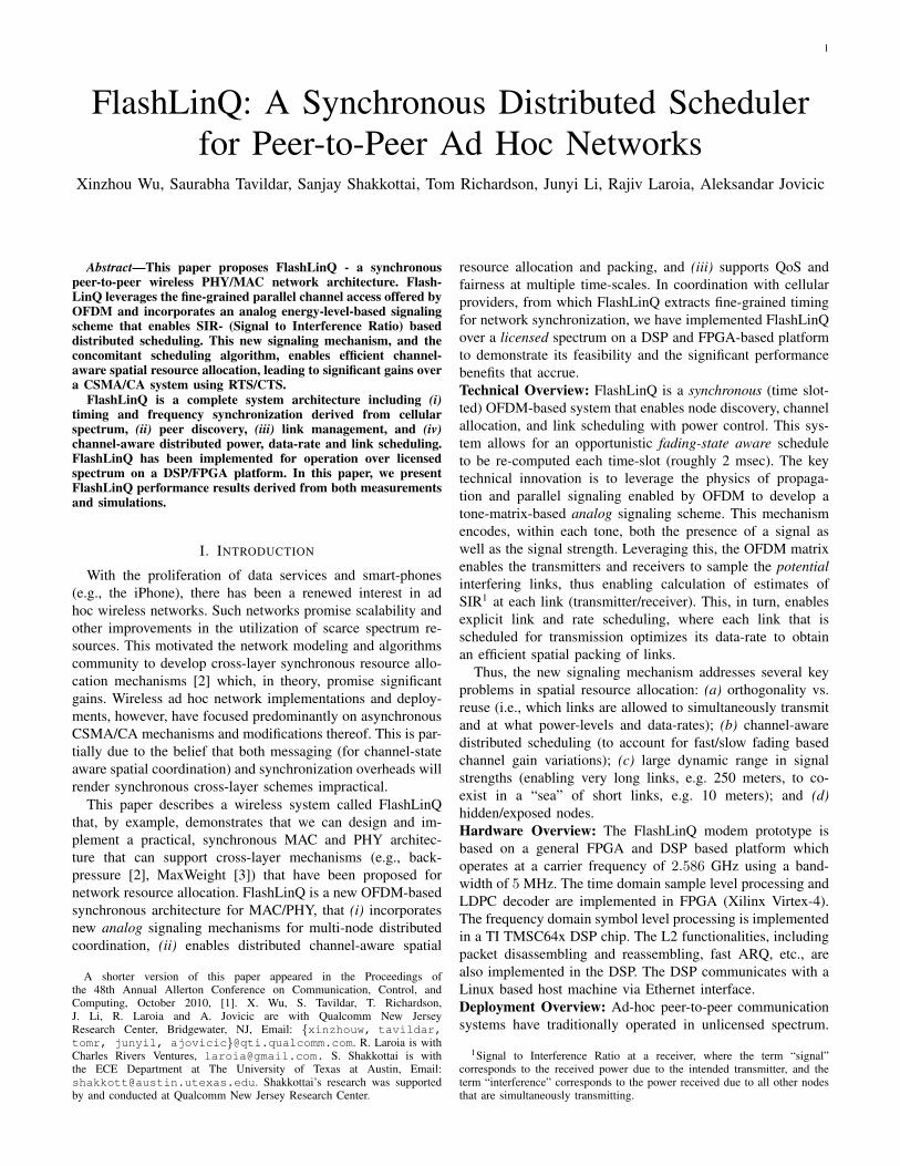
Fig. 2. The FlashLinQ operation timeline: data transmissions occur in slottedtime of around 2 msec each. Within each slot, link and rate schedulingis followed by the actual data transmission. In addition, every 1 second,resources are allocated for other channels such as peer discovery and linkmanagement.
first describe the key ideas underlying our algorithm and thendescribe the signaling mechanisms that enable the approach.
As discussed in Section I-A, the goal of FlashLinQ is toschedule a channel-state aware maximal feasible set of linksfor any given time slot based on the current traffic and channelconditions. The feasible set is defined based on the link SIRs,i.e., all links in the chosen independent set simultaneouslyhave a “large enough” SIR.
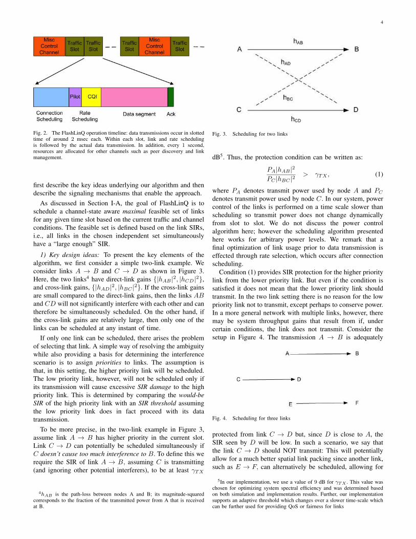
1) Key design ideas: To present the key elements of thealgorithm, we first consider a simple two-link example. Weconsider links A → B and C → D as shown in Figure 3.Here, the two links4 have direct-link gains {|hAB |2, |hCD|2},and cross-link gains, {|hAD|2, |hBC |2}. If the cross-link gainsare small compared to the direct-link gains, then the links ABand CD will not significantly interfere with each other and cantherefore be simultaneously scheduled. On the other hand, ifthe cross-link gains are relatively large, then only one of thelinks can be scheduled at any instant of time.
If only one link can be scheduled, there arises the problemof selecting that link. A simple way of resolving the ambiguitywhile also providing a basis for determining the interferencescenario is to assign priorities to links. The assumption isthat, in this setting, the higher priority link will be scheduled.The low priority link, however, will not be scheduled only ifits transmission will cause excessive SIR damage to the highpriority link. This is determined by comparing the would-beSIR of the high priority link with an SIR threshold assumingthe low priority link does in fact proceed with its datatransmission.
To be more precise, in the two-link example in Figure 3,assume link A → B has higher priority in the current slot.Link C → D can potentially be scheduled simultaneously ifC doesn’t cause too much interference to B. To define this werequire the SIR of link A → B, assuming C is transmitting(and ignoring other potential interferers), to be at least γTX
4hAB is the path-loss between nodes A and B; its magnitude-squaredcorresponds to the fraction of the transmitted power from A that is receivedat B.
Fig. 3. Scheduling for two links
dB5. Thus, the protection condition can be written as:
PA|hAB |2
PC |hBC |2> γTX , (1)
where PA denotes transmit power used by node A and PC
denotes transmit power used by node C. In our system, powercontrol of the links is performed on a time scale slower thanscheduling so transmit power does not change dynamicallyfrom slot to slot. We do not discuss the power controlalgorithm here; however the scheduling algorithm presentedhere works for arbitrary power levels. We remark that afinal optimization of link usage prior to data transmission iseffected through rate selection, which occurs after connectionscheduling.
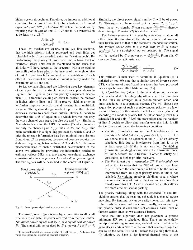
Condition (1) provides SIR protection for the higher prioritylink from the lower priority link. But even if the condition issatisfied it does not mean that the lower priority link shouldtransmit. In the two link setting there is no reason for the lowpriority link not to transmit, except perhaps to conserve power.In a more general network with multiple links, however, theremay be system throughput gains that result from if, undercertain conditions, the link does not transmit. Consider thesetup in Figure 4. The transmission A → B is adequately
Fig. 4. Scheduling for three links
protected from link C → D but, since D is close to A, theSIR seen by D will be low. In such a scenario, we say thatthe link C → D should NOT transmit: This will potentiallyallow for a much better spatial link packing since another link,such as E → F, can alternatively be scheduled, allowing for
5In our implementation, we use a value of 9 dB for γTX . This value waschosen for optimizing system spectral efficiency and was determined basedon both simulation and implementation results. Further, our implementationsupports an adaptive threshold which changes over a slower time-scale whichcan be further used for providing QoS or fairness for links
5
higher system throughput. Therefore, we impose an additionalcondition for a link C → D to be scheduled: D shouldexpect adequate SIR if scheduled. We define the condition byrequiring that the SIR of link C → D due to A’s transmissionat be least γRX dB: 6
PC |hCD|2
PA|hAD|2> γRX (2)
These two mechanisms ensure, in the two link scenario,that the high priority link is protected and both links getscheduled only if the cross-link gains are “weak enough”. Byrandomizing the priority of links over time, a basic level of“fairness” across links can be maintained in the sense thatall links will have access to the spectrum with a schedulingprobability of at least 1
|Nl| , or the inverse of the neighbor sizeof link l. Here two links are said to be neighbors of eachother if they cannot be scheduled simultaneously under theconstraints of (1) and (2).
So far, we have illustrated the following three key elementsof our algorithm in the simple network examples shown inFigure 3 and Figure 4: (i) a fair priority assignment mecha-nism; (ii) a transmit yielding criterion to protect the receiverin higher priority links; and (iii) a receive yielding criterionto further improve network spatial packing in a multi-linkscenario. The system design needs to provide the relevantdevices a means to check these criteria. Device C needs todetermine the LHS of equation (1) which involves not onlythe cross channel gain hBC , but also PA and hAB . Similarly,D needs to determine the LHS of equation (2) which involvesnot only the channel gain hCD, but also PA and hAD. Ourmain contribution is a signalling protocol by which C and Dinfer the relevant information based on minimal transmissionsfrom A and B. In particular, the protocol does not require anydedicated signaling between links AB and CD. The mainmechanism used to enable distributed determination of theabove two criteria by providing the information needed toestimate various SIRs is a two analog-tone-signal exchangeconsisting of a inverse power echo and a direct power signal.The two signals will be described in the context of Figure 5.
Fig. 5. Direct power signal and inverse power echo
The direct power signal is sent by a transmitter to allow allreceivers to estimate the power received from that transmitter.The direct power signal sent by A is a signal sent at powerPA. The signal will be received by D at power PA× |hAD|2.
6In our implementation, we use a value of 9 dB for γRX . As before, thisvalue was chosen for optimizing spectral efficiency.
Similarly, the direct power signal sent by C will be of powerPC . This signal will be received by D at power PC ×|hCD|2.From these two signals, D can estimate PC×|hCD|2
PA×|hAD|2 therebydetermining if Equation (2) is satisfied or not.
The inverse power echo is sent by a receiver to allow allother transmitters to estimate the ratio of the received power oftheir transmission to that of the receiver’s intended transmitter.The inverse power echo is a signal sent by B at power
KPA|hAB |2 for a well-defined system constant K. The signal
will be received by C at power rp = K|hBC |2PA|hAB |2 . From this, C
can now form the SIR estimate:
PA × |hAB |2PC × |hBC |2
=K
rp × PC. (3)
This estimate is then used to determine if Equation (1) issatisfied or not. We note that a similar idea of inverse powerCTS, via the use of out-of-band busy tones, has been proposedin an asynchronous 802.11-like setting [23].
2) Algorithm description: In the network setting, we con-sider a cascaded scheduling algorithm where the prioritiesof the links are arranged in a pseudo-random order, andlinks scheduled in a sequential manner. (We will discuss theacquisition process of such a pseudo-random priority in a latersection III-A3.) In other words, the links are strictly orderedaccording to a random priority list. A link at priority level L isscheduled if and only if both the transmitter and the receiverof link L decide to allow data transfer over this link. It willdecide to transmit under the following conditions.
• The link L doesn’t cause too much interference to analready scheduled link (i.e., of priority {1, 2, . . . , L−1}:we define this to be satisfied if the SIR of an alreadyscheduled link due to interference from link L to beat least γTX dB. If this is not satisfied, Tx-yielding(transmitter yielding) occurs, where the transmitter nodeof link L decides not to transmit in order to satisfy SIRconstraints at higher priority receivers.
• The link L will see a reasonable SIR if scheduled: wedefine this to mean that the SIR of link L is at leastγRX dB where the interference is taken to be the sum ofinterference from all higher priority links. If this is notsatisfied, Rx-yielding (receiver yielding) occurs, wherethe receiver node of link L decides not to allow datatransfer over this link. As we discussed earlier, this allowsfor more efficient spatial packing.
The priority ordering, along with the cascaded Tx and Rx-yielding ensures that the resulting schedule is a channel-awarematching. By iterating, it can be easily shown that this algo-rithm leads to a maximal matching. Finally, re-randomizingthe priority order at each time slot ensures a basic level offairness across links as we discussed before.
Note that this algorithm does not guarantee a preciseminimum SIR for a scheduled link. There are potentiallymultiple interfering transmitters, each of which individuallyguarantees a certain SIR to a receiver, that combined togethercan cause the actual SIR to fall below the yielding threshold.(In addition, we have so far ignored thermal noise at the

6
receiver.) This is addressed by using a rate scheduling mech-anism that subsequent to the scheduling operation performsan SIR estimation based on wide-band pilots from all thescheduled transmitters (see Section III-A3). This estimatedSIR (based on total interference) is used to determine the coderate and modulation to be used for each of the links for a giventime slot. This is further discussed in Section IV-B.
3) Signaling design: As discussed earlier, the basic datatransfer unit is a time slot, with each slot being 2.08 mil-liseconds in duration. Each slot occupies the entire 5 MHz,and a scheduling decision is made on per slot basis andindependently of other slots. Further, each slot is divided intofour physically separate subchannels (see Figure 6): connec-tion scheduling, rate scheduling, data segment and ACK, eachdescribed below.
Connection scheduling: Each link has an associated locallyunique connection ID (or CID) which is an index between 1and 112, which is acquired as part of the link managementprocess. When there are more than 112 links present in acollision domain, new devices cannot find a free CID inthe “slower” link management, and thus cannot participate inthe FlashLinQ scheduling phase (see Section III-D for moredetails on CID acquisition). They however periodically probefor a free CID; when available, they can capture it and thenparticipate in connection scheduling and data transmission asdescribed below.
For every slot, connection scheduling signaling consists oftwo signaling blocks: Tx-block and Rx-block, as shown inFigure 6. Both Tx-block and Rx-block have four OFDM-symbols with FFT size 32, i.e, each symbol has 32 differenttones (or sub-carriers), out of which, 28 are usable for signaltransmission. A link with an assigned CID corresponds to apair of single tones, one in Tx-block, to be used for transmitter,and the other in Rx-block, to be used for receiver. Themapping from the CIDs to the actual tone pair within theconnection scheduling blocks is randomized (every time-slot,a new mapping is used). Figure 6 shows a realization for twoCIDs, say 3 and 7.
Recall that the scheduling algorithm described earlier inthis section requires (i) a mechanism for sending analogsignals between Tx-Rx pairs, (ii) that these signals should notinterfere with each other, and (iii) a priority ordering amonglinks. The tone matrix of single-tone pairs satisfies all theserequirements: these tones are orthogonal and analog, and anatural priority ordering is assigning the highest priority tothe top-left tone-pair and the lowest to the bottom-right, andwith lexicographical ordering (the ’x’ coordinate has higherpriority than the ’y’ coordinate) – thus in Figure 6, CID7 has higher priority than CID 3. The random remappingof CIDs to tone pairs for each time-slot ensures fairnessacross links. To elaborate, each link has a Connection ID(CID) that is associated with it in the link management outercontrol (see Section III-D). The priority of links is drivenby this Connection ID. This connection ID is mapped to apriority level (that is time-varying). Since two links in thesame collision domain have different Connection IDs, thisensures that tones are not in conflict if the mapping is unique(i.e., two links do not take the same priority). There are two
implementations of the mapping between the CID and priority– one, via a deterministic table mapping CID to priority-levelthat is hardwired into each device, and another via a globalpseudo-random number generator in the FlashLinQ system(i.e., same algorithm and seed at each device).
Fig. 6. Structure of connection scheduling
To use the language of WiFi, the Tx-block is analogousto the RTS block and the Rx-block is analogous to the CTSblock. The purpose of these two blocks is as follows:• The Tx-block is used by potential transmitters to make a
request to be scheduled. The transmitter node “lights up”(i.e., transmits power on) the symbol and tone allocated toit in the Tx-block. This request is a direct power signal,that is it is sent at power that would be used for the trafficchannel. All the potential receivers listen to the Tx-blocksand determine if they need to perform Rx-yielding.
• The Rx-block If a receiver chooses to Rx-yield, it doesnot respond (i.e., sends no power in the symbol allocatedto the link in the Rx-block); other-wise it “lights up”its symbol and tone using its inverse echo power leveldescribed earlier in this section. All the transmitters listento all the tones and symbols in the Rx-block to determinewhether to Tx-yield.
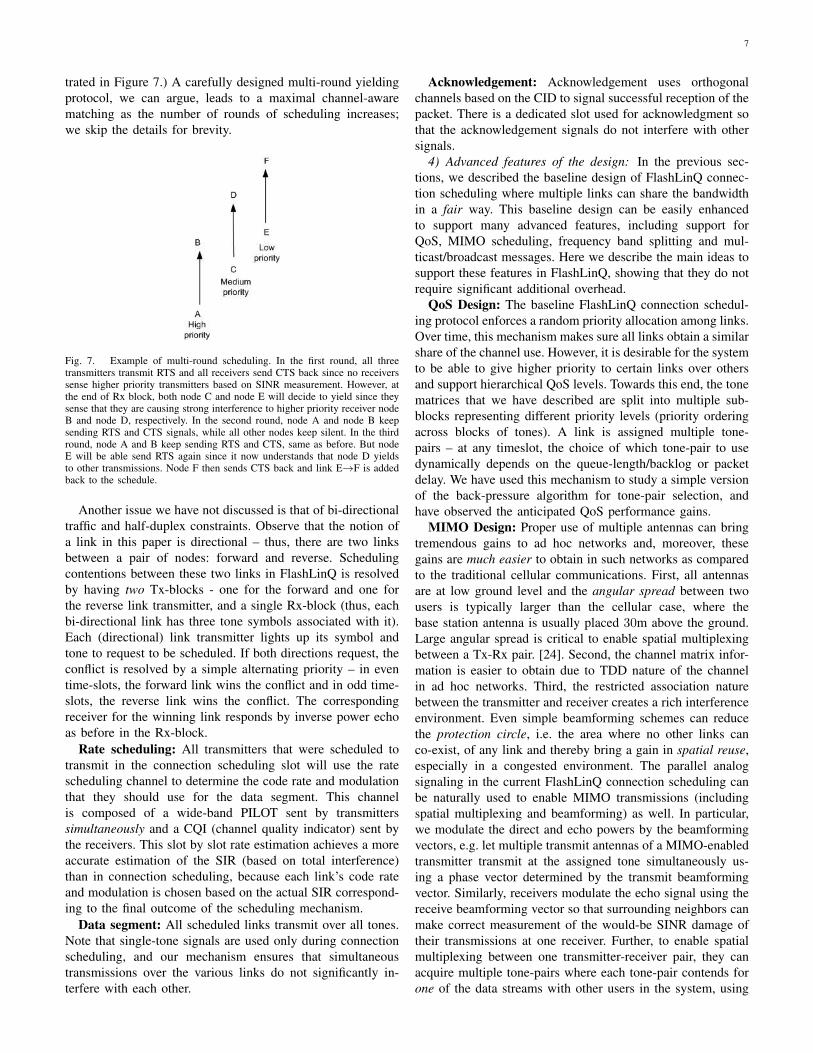
A link is scheduled if neither the transmitter nor the receiveryields. This operation is repeated over multiple rounds (seeFigure 6, where the tone matrix is repeated multiple times)to optimize the packing – in subsequent rounds, additionallinks can be added, but already scheduled links will not yield.We now provide a high level overview about the multi-roundscheduling protocol. In each round, the surviving links fromprevious rounds of scheduling keeps transmitting RTS andCTS beacon. However, the links which have decided to yieldearlier can have another chance to decide whether they can beadded. For example, links which yielded in the Rx block fromprevious rounds can measure the energy in the Rx block againin the current round to see whether the link(s) causing theyielding decision previously survives the previous scheduling.(A more detailed example of multi-round operation is illus-
7
trated in Figure 7.) A carefully designed multi-round yieldingprotocol, we can argue, leads to a maximal channel-awarematching as the number of rounds of scheduling increases;we skip the details for brevity.
Fig. 7. Example of multi-round scheduling. In the first round, all threetransmitters transmit RTS and all receivers send CTS back since no receiverssense higher priority transmitters based on SINR measurement. However, atthe end of Rx block, both node C and node E will decide to yield since theysense that they are causing strong interference to higher priority receiver nodeB and node D, respectively. In the second round, node A and node B keepsending RTS and CTS signals, while all other nodes keep silent. In the thirdround, node A and B keep sending RTS and CTS, same as before. But nodeE will be able send RTS again since it now understands that node D yieldsto other transmissions. Node F then sends CTS back and link E→F is addedback to the schedule.
Another issue we have not discussed is that of bi-directionaltraffic and half-duplex constraints. Observe that the notion ofa link in this paper is directional – thus, there are two linksbetween a pair of nodes: forward and reverse. Schedulingcontentions between these two links in FlashLinQ is resolvedby having two Tx-blocks - one for the forward and one forthe reverse link transmitter, and a single Rx-block (thus, eachbi-directional link has three tone symbols associated with it).Each (directional) link transmitter lights up its symbol andtone to request to be scheduled. If both directions request, theconflict is resolved by a simple alternating priority – in eventime-slots, the forward link wins the conflict and in odd time-slots, the reverse link wins the conflict. The correspondingreceiver for the winning link responds by inverse power echoas before in the Rx-block.
Rate scheduling: All transmitters that were scheduled totransmit in the connection scheduling slot will use the ratescheduling channel to determine the code rate and modulationthat they should use for the data segment. This channelis composed of a wide-band PILOT sent by transmitterssimultaneously and a CQI (channel quality indicator) sent bythe receivers. This slot by slot rate estimation achieves a moreaccurate estimation of the SIR (based on total interference)than in connection scheduling, because each link’s code rateand modulation is chosen based on the actual SIR correspond-ing to the final outcome of the scheduling mechanism.
Data segment: All scheduled links transmit over all tones.Note that single-tone signals are used only during connectionscheduling, and our mechanism ensures that simultaneoustransmissions over the various links do not significantly in-terfere with each other.
Acknowledgement: Acknowledgement uses orthogonalchannels based on the CID to signal successful reception of thepacket. There is a dedicated slot used for acknowledgment sothat the acknowledgement signals do not interfere with othersignals.
4) Advanced features of the design: In the previous sec-tions, we described the baseline design of FlashLinQ connec-tion scheduling where multiple links can share the bandwidthin a fair way. This baseline design can be easily enhancedto support many advanced features, including support forQoS, MIMO scheduling, frequency band splitting and mul-ticast/broadcast messages. Here we describe the main ideas tosupport these features in FlashLinQ, showing that they do notrequire significant additional overhead.
QoS Design: The baseline FlashLinQ connection schedul-ing protocol enforces a random priority allocation among links.Over time, this mechanism makes sure all links obtain a similarshare of the channel use. However, it is desirable for the systemto be able to give higher priority to certain links over othersand support hierarchical QoS levels. Towards this end, the tonematrices that we have described are split into multiple sub-blocks representing different priority levels (priority orderingacross blocks of tones). A link is assigned multiple tone-pairs – at any timeslot, the choice of which tone-pair to usedynamically depends on the queue-length/backlog or packetdelay. We have used this mechanism to study a simple versionof the back-pressure algorithm for tone-pair selection, andhave observed the anticipated QoS performance gains.
MIMO Design: Proper use of multiple antennas can bringtremendous gains to ad hoc networks and, moreover, thesegains are much easier to obtain in such networks as comparedto the traditional cellular communications. First, all antennasare at low ground level and the angular spread between twousers is typically larger than the cellular case, where thebase station antenna is usually placed 30m above the ground.Large angular spread is critical to enable spatial multiplexingbetween a Tx-Rx pair. [24]. Second, the channel matrix infor-mation is easier to obtain due to TDD nature of the channelin ad hoc networks. Third, the restricted association naturebetween the transmitter and receiver creates a rich interferenceenvironment. Even simple beamforming schemes can reducethe protection circle, i.e. the area where no other links canco-exist, of any link and thereby bring a gain in spatial reuse,especially in a congested environment. The parallel analogsignaling in the current FlashLinQ connection scheduling canbe naturally used to enable MIMO transmissions (includingspatial multiplexing and beamforming) as well. In particular,we modulate the direct and echo powers by the beamformingvectors, e.g. let multiple transmit antennas of a MIMO-enabledtransmitter transmit at the assigned tone simultaneously us-ing a phase vector determined by the transmit beamformingvector. Similarly, receivers modulate the echo signal using thereceive beamforming vector so that surrounding neighbors canmake correct measurement of the would-be SINR damage oftheir transmissions at one receiver. Further, to enable spatialmultiplexing between one transmitter-receiver pair, they canacquire multiple tone-pairs where each tone-pair contends forone of the data streams with other users in the system, using
8
corresponding transmit and receive beamforming vectors.FDM Design: In the baseline design, all scheduled links
transmit simultaneously over all tones. Instead, one can po-tentially split the data segment into multiple parallel blocks(frequency band splitting into four blocks of 1.25 MHz each)– we have observed that this is useful (can potentially doublethe measured throughput) in settings with a few very long links(e.g., 500 meters), requiring a low rate, and many short links,requiring higher rate. This band-splitting modification enablessimultaneous scheduling of long links with the short linksby using a simple modification of the scheduling algorithmsdescribed above.
Multi-tone Design for Mitigating Frequency SelectiveFading: As mentiond earlier, single tone signaling has lowPAPR, which can be exploited in connection scheduling byincreasing transmit power. On the other hand, connectionscheduling with single tone signaling might suffer from fre-quency selective fading, e.g., the channel on the selectedtone might be in a deep fade and the power measured onthat tone would then poorly represent the overall channelquality. When FlashLinQ is considered for deployment inenvironments with extensive multipath delay spread a multi-tone connection scheduling should be considered. In this case,a CID corresponds to multiple tone pairs, e.g. four, that are“spread-out” across the frequencies within the tone matrix.Yielding decisions will then be based on the average measuredenergy over the multiple tone-pairs. This mitigates frequencyselective fading and improves the SINR estimate made duringconnection scheduling. The rate scheduling signals use wide-band pilot signals and are therefore inherently robust againstfrequency selective fading.
Broadcast Design: Another important feature of the Flash-LinQ design is its support of reliable broadcast and multicast.A characteristic capability of the FlashLinQ system is the peerdiscovery, see Section III-C. During the peer discovery phase,mobiles exchange identity and interests with each other; thepeer discovery channel is essentially a light-weight broadcastchannel. The data rate for the peer discovery channels isintentionally quite low (72 bits per user every 8 seconds)to ensure low system overhead, low power consumption, andrelatively large range. In addition to peer discovery, to supporthigher rate broadcast messages, FlashLinQ can provision ad-ditional periodic traffic resources for dedicated broadcast. Forexample, one out of 25 traffic slots can be designated broadcastslots. During these traffic slots, the data segment is furtherpartitioned into multiple, e.g. 9, transmission blocks. Multipletransmitters compete separately in corresponding connectionscheduling blocks for the use of these transmission blocks. Theconnection scheduling block is also tailored for the broadcastnature of the transmissions, in which traffic from a singletransmitter is supposed to reach multiple receivers. Overall,in addition to the peer discovery capability, FlashLinQ cansupport up to 1800 bits/s of broadcast messages for eachtransmitter.
B. Timing SynchronizationAd-hoc networks are usually conceived as operating
largely asynchronously in unlicensed spectrum. Synchroniza-
tion brings many advantages but achieving synchronizationin a distributed wireless system is a resource and energyintensive problem. In the FlashLinQ system, which operates inlicensed spectrum, we achieve synchronization using existinginfrastructure. In particular, we use CDMA systems deployedin the US that send unscrambled signals from which fine-grained timing and frequency information can be derived. InEurope, DVB-H is a potential source for such timing andfrequency information. In addition, one can envision deployingan in-band timing source explicitly for this purpose (we havedone this for our prototype system, see Section IV).
However, base stations may not be completely synchronizedto each other, which may lead to timing offsets betweennodes on cell boundaries, causing FLQ devices to fail todetect timing signals in the presence of channel fading. Thus,residual timing errors can remain even with infrastructurebased synchronization. We address this problem using a twostep approach:• Secondary timing synchronization: this protocol works in
the FlashLinQ spectrum and is used to correct the timingerrors between different nodes after synchronization tothe base station. Note that the secondary timing syn-chronization protocol solves the problem of distributedsynchronization for the case when all nodes have alreadyachieved rough synchronization. This is a much simplerproblem than a completely distributed synchronizationproblem.
• Larger cyclic prefix (CP): The residual errors after thesecondary timing synchronization protocols are accom-modated by using a larger CP for the OFDM system,one that covers for propagation delay as well as timingerrors.
For our system, the timing synchronization algorithm achievestiming synchronization to within the propagation delay (max-imum of 5 microseconds) between different nodes.
C. Peer discoveryThe peer discovery mechanism enables nodes to discover
the presence of other nodes in their neighborhood, whichis about a 1 km range. This long range is facilitated byusing rateless codes to broadcast peer IDs, enabling discoveryat extremely low SNR over moderate timescales. Here, webriefly summarize two important aspects of peer discovery.The details are not discussed in this paper since the focus ofthis paper is on the scheduling algorithm.
Energy efficiency: One of the chronic concerns about peerdiscovery in ad hoc wireless networks is the energy efficiencyof the process. We use synchronization (Section III-B) todedicate small time slots for the purpose of peer discovery(roughly 20 ms per second). This time slot is used fortransmitting as well as receiving presence information to andfrom nearby nodes. In our system, this amounts to a 2% activeduty cycle, which leaves an acceptable device standby time.All devices participate in peer discovery even if they are notactively communicating with other devices.
Discovery performance: The peer discovery time slot ispartitioned into orthogonal resources using the robust orthog-onalization inherent in OFDM: each resource uses a subset

9
of the tone-time matrix determined by OFDM for the peerdiscovery slot. A node monitors the peer discovery channel andpicks a locally unused resource to transmit on. The node thensends coded information using codes similar to fountain codes.In our study, we have seen that the protocol can successfullydiscover up to a few thousand devices over a 1 km radius andwithin, roughly, a 10 - 15 second time interval.
D. Link management
After a device detects another device of interest in peerdiscovery, it may page that device to establish a link betweenthe two devices. The paging channels are a set of timerecurring resources (every 1 second) which support multiplesimultaneous pages with low failure probability. As part ofthe paging process, the transmitter and receiver exchange useridentity and other authentication information to establish alink. Another important component of the link establishmentprocess is the acquisition and determination of a locallyunique connection identifier (CID) that is used in connectionscheduling to identify the link. For managing this resource weprovision a special channel, the CID channel, which operatesin conjunction with paging, This allows devices to monitorCID usage and identify a viable resource using the protocoldescribed below.
We assume that links remain in the system for long periodsof time (a few seconds) relative to a communication burst(2.08 ms). This assumption is used to allocate distinct linkidentifiers (CID) to each (local) link, that are used during thescheduling process. Note that, even though we assume thatthe links communicate over relatively long periods of time,the traffic itself may be bursty in nature. As described below,CIDs are selected based on a SIR criterion that is analogousto that used in link scheduling.
Before we describe the CID selection algorithm, we need tofirst address the meaning of local uniqueness in this context.We define local uniqueness in terms of SIR rather thaninterference. The motivation for this is similar to that for thelink scheduling algorithm: for a wireless system, the criterionof importance is the SIR, and not merely the absolute signaland interference levels.
To be specific, consider two links A ↔ B and C ↔ D.The various channel gains associated to them are shown inFigure 8. The transmit powers used by nodes are denoted asPA, PB , etc.
Fig. 8. CID Reuse
We say that a link A ↔ B can reuse a CID with a linkC ↔ D (A ↔ B is not local to C ↔ D) if the following
conditions are satisfied:
min(PB |hAB |2
PC |hAC |2,PB |hAB |2
PD|hAD|2) > SIRthreshold, (4)
min(PA|hAB |2
PC |hBC |2,PA|hAB |2
PD|hBD|2) > SIRthreshold, (5)
min(PD|hCD|2
PA|hAC |2,PD|hCD|2
PB |hBC |2) > SIRthreshold, (6)
min(PC |hCD|2
PA|hAD|2,PC |hCD|2
PB |hBD|2) > SIRthreshold, (7)
where SIRthreshold is a constant, set to be 20 dB for our sys-tem. The motivation for this definition is as follows: equation(4) says that the SIR seen by A when B is transmitting to A,and simultaneously C is transmitting to D, or D is transmittingto C is at least SIRthreshold. Similarly, equations (5), (6),and (7) ensure that the SIRs seen by B, C, and D shouldbe at least SIRthreshold. If all these equations are satisfied itmeans link A ↔ B does not interfere significantly with linkC ↔ D, and hence they can use the same CID. Note theSIRthrehold (20dB) here is chosen to be much larger than thescheduling yielding threshold γTX and γRX (9dB) as definedin (1) and (2). Roughly speaking, the CID selection protocolensures that the CID is not reused by another link within thetwo-hop neighborhood of any link.
This raises the question of how to design a distributedsystem that allocates CIDs so that equations (4) to (7) aresatisfied for every pair of links. The main idea here is touse analog signals: inverse power echo and a direct powersignal, described in Section III-A. We assume that for eachlink A ↔ B, both A and B know the powers PA and PB aswell as the channel gain hAB (similarly for C ↔ D; powersare known due to FlashLinQ design parameters, and channelgains are learned analogous to connection scheduling).
The protocol uses a dedicated signaling resource for CIDselection. The resource occupies roughly 1 millisecond everysecond. The resource is partitioned into orthogonal compo-nents, using OFDM tone-time matrix, one for each CID. Eachcomponent contains four sub-resources (elementary complexdegrees of freedom). The protocol followed by an active link(say A ↔ B ) that has a CID is as follows:
1) A uses two sub-resources to send out two signals thatindicate that the CID is currently being used: a directpower signal and an inverse power echo.
2) B uses the other sub-resources to send out a direct powersignal and an inverse power echo.
The protocol followed by a link (say C ↔ D ) that wantsto grab a CID is as follows. C monitors all the sub-resourcesfor each CID. For each CID, based on the power received, itdecides whether that CID can be used while still satisfyingequations (4) and (5). This is done as follows:
1) Using A’s direct power signal, C estimates PD|hCD|2PA|hAC |2 .
2) Using A’s inverse power echo, C estimates PC |hAC |2PB |hAB |2 .
3) C similarly uses the two signals sent by B.D follows a protocol similar to C’s protocol described above.Based on this, C and D both jointly determine through amessage exchange for each CID if the equations (4) to (7)are met for a given CID and then agree upon a CID.

10
E. Comparison with 802.11
In this section, we summarize some of the key differenceswith the 802.11g (CSMA/CA with RTS/CTS) protocol. Thesebenefits will be quantified through measurements and simula-tions in Section IV.
1) Synchronization: FlashLinQ is a time slotted system.This allows FlashLinQ to have dedicated slots for con-nection scheduling as well as rate scheduling. The directimpact of this is that it reduces system overhead. A moreindirect benefit for FlashLinQ is that it enables many al-gorithms that are hard to implement in an asynchronoussystem. Arguably, one can incorporate many of the ideasin this paper into 802.11, but the asynchronous natureof 802.11 makes the implementation significantly moredifficult, and the resulting gains much lower.
2) Tx-Rx yielding: In FlashLinQ, transmitters yield onlybased on receiver echoes and do not yield to other trans-mitters. Similarly, receivers yield only to other transmit-ters. This is in contrast with 802.11 where transmittersand receivers both yield to transmitters (CSMA/CA) ortransmitters and receivers both yield to transmitters aswell as receivers (RTS/CTS). The FlashLinQ approachenables more spatial reuse, and solves the hidden nodeproblem without a spatial reuse penalty.
3) Spatial reuse: In 802.11 the reuse decisions are madebased on sensing, meaning that the reuse radius is fixedand independent of the length of the primary link. Fur-ther, the reuse region is drawn around the transmitter andexcludes both transmitters and receivers7. This makesthe 802.11 reuse decision highly suboptimal, particularlyfor short links. On the other hand, in FlashLinQ the reuseradius depends on the primary link length; the shorter theprimary link, shorter the reuse radius. This is illustratedin Figure 1.
4) Power control: In FlashLinQ, short links can use lowertransmit power and hence can coexist with long linksthat use higher transmit power. This is akin to beingable to whisper (short range communication) in a largelecture hall without interrupting the lecture for otheraudience members (long range communication). In Fig-ure 9, C can transmit to D at lower power since Dis close to C thereby allowing A to transmit to Bsimultaneously. We discussed the power control issuein much greater details in a separate paper [25].
Fig. 9. Power control facilitates reuse
5) Rate scheduling: In FlashLinQ, we have dedicated perslot rate scheduling in which interference estimationis done before every transmission. This provides muchmore robust rate scheduling than 802.11 rate scheduling
7This is true in the case of CSMA/CA. If RTS/CTS is incorporated, thereuse region is around both transmitter and receiver, and excludes othertransmitters and receivers
which is typically based on ack/nak. It is particularlyuseful in a dynamic interference environment.
6) Range: From a link budget point of view, FlashLinQ’straffic link is supported at 14 dB lower power than802.11, thus inherently supporting longer links. Thiscorresponds to 2X-3X range improvement dependingon the propagation environment. From a schedulingperspective, the FlashLinQ mechanism enables longerlinks to periodically “win” a chance to get scheduled –in 802.11, it is hard to sustain long links due to a lackof MAC-level coordination.
IV. IMPLEMENTATION AND SIMULATIONS
In this section, we evaluate the efficiency of FlashLinQlink scheduling by experiments using the FlashLinQ prototypedevices and also simulations.
A. Measurement Setup and Results
The FlashLinQ prototype modem (as shown in Figure 10) isbased on a general FPGA/DSP based platform which operatesat 2.586GHz carrier frequency. We chose TI DSP chipsetTMS-C6482 and XiLinx Virtex-4 FPGA to build the OFDMAbased FlashLinQ physical layer modules. Specifically, thetime-domain sample rate processing and FFT are performedin the FPGA and frequency domain symbol level processingis performed mainly in the DSP. As a result of this separation,the link scheduling algorithms reside in the DSP. Furtherimplementation details are available in [26].
Fig. 10. Prototype modem.
Our experiments are conducted with four devices namedAMC Theaters (AT), Movie Buff (MB), Teen Shopper (TS)and Pub Patron (PP). The first set of results shows how Flash-LinQ devices make transmitting or yielding decisions (spatialpacking) at different channel conditions. In this experiment,we have four devices forming two links, one between AT andMB and the other between TS and PP. We let the four ofthem sit on a straight line (as shown in Figure 11) withina room. In the beginning of the experiment, we let the twotransmitters, TS and AT, stay at the far sides of the picture(about 3 meters away from each other) and the two receivers,PP and MB close to their interferers. We then move PP andMB closer to their transmitters and thus create strong signaland weaker interference for both links. In FlashLinQ, since theyielding decisions are made upon SIRs instead of measuredenergy levels of the interference, we would expect the twolinks to orthogonalize the channel use in the beginning of the

11
experiment and switch to full reuse when the interferers arenot strong enough. Note that if a 802.11 type of protocol isused, fully orthogonalization is the only possible result since,in our experiment, each node is well within the carrier sensingrange of any other node in the system, including its intendedtransmitter or receiver and also its interferers.
Fig. 11. Reuse versus orthogonalization experiment setup
To collect the data, the modem reports its current linkscheduling status to the Linux based host every second.Figure 12 shows plots for the sum rate (the top window)and individual rates for TS, PP, MB, and AT (the bottom 4windows in that order) along Y-axis versus time along theX-axis. Since the traffic was unidirectional, two of the nodes(TS and AT) report zero rate throughout. From Figure 12, wecan see that both links are yielding to the other transmitter inthe beginning of the experiment and both links achieve halfof the full capacity. Since FlashLinQ guarantees fair sharingof the air interface between the contending links, both linksget 50% of the resource. When the two receivers move closerto their intended transmitter, both users get scheduled in alltraffic slots by reusing the available bandwidth. We remarkthat in these experiments, we only enabled low rate optionswith at peak rate limit of 1.5Mbits/s.
Fig. 12. Measurement data as a time series.
The second set of measurements are collected by repeatingthe previous experiments with different yielding thresholds.The emphasis here is to show the importance of SIR basedyielding as compared to energy-measurement based yielding,e.g., the carrier sensing protocol in 802.11, and also fullreuse. In particular, we compare the system behavior underthe following three different choices of yielding thresholds:(1) Both transmit and receive yielding threshold to be around9dB: this is the normal operation of FlashLinQ; (2) Bothtransmit and receive yielding threshold to be around 18dB:this choice of yielding threshold has a strong bias towardsorthogonalization. The purpose of this scenario is to mimicthe behavior of 802.11; and (3) Both transmit and receiveyielding are disabled, i.e. the yielding thresholds are chosen tobe −∞dB: this forces all devices to reuse the full spectrum,
regardless the surrounding environment. The measured resultsare shown in Figure 13. In the low interference scenario,where two links are geographically separated, yielding thresh-old choices at −∞ and 9 dB lead to similar result sinceboth links see little interference from the other link. Yet theaggressive threshold of 18 dB suffers since it orthogonalizesunnecessarily and thus gets only 50% of the full capacity. Inthe strong interference case where the receivers get closer totheir interfering transmitters, the results obtained with 9dB and18dB yielding threshold are roughly the same since both forcethe two links to orthogonalize which is better than completelyreusing the spectrum. However, the performance with fullreuse is much worse since both links transmit simultaneouslybut with bad SIRs. It can be easily seen here that a properchoice of the yielding threshold can achieve a good throughputin both strong and weak interference scenarios.
Fig. 13. Lab measurement data with different yielding thresholds.
B. Simulation Results
In this section, we present simulation results comparingFlashLinQ with a 802.11g protocol. Our simulations are basedon a detailed software implementation of both FlashLinQand 802.11g, and all signaling overheads are fully accounted.The FlashLinQ system operates over a 5 MHz spectrum(for which this system is designed), whereas the 802.11gprotocol operates over a 20 MHz spectrum. Our results arehence normalized to bits/sec/Hz to account for the excessbandwidth for 802.11g. For the WiFi protocol, as per 802.11gspecifications, an energy sensing threshold of −76 dBm andPLCP header decoding (at 0.5 dB SINR) is used for yielding.
Before discussing the simulation settings, it is important tonote that there are several design modifications that can bemade to 802.11g, such as out-of-band SIR based signaling[23], power and rate control, etc., that can lead to improvedperformance of the 802.11g system. However, as our simu-lations are based on a detailed software implementation, thiswould require us to fully spec-out such a system, which isbeyond the scope of our work here. In any case, our main

12
Indoor OutdoorFlashLinQ 125 17.3
802.11g 21.2 3.2
TABLE ISUM RATE (BITS/SEC/HZ) FOR 256 LINKS.
objective here is to demonstrate that we can indeed design asynchronous and distributed opportunistic scheduling systemthat is competes well with traditional 802.11g systems, evenafter accounting for all signaling overheads.
We simulate both outdoor and indoor settings. For theoutdoor deployment, links are dropped randomly in a 1000m×1000m square. Link lengths are chosen to be 20m. To removethe boundary effect, we use a wrap-around model (torus) inthe signal strength calculation between any two nodes. Thepathloss between any two nodes is modeled using an ITU-1411LOS model with antenna height of 1.5 meters (see [27] for asummary of channel models). For the indoor deployment, linksare dropped randomly in a 50m× 100m× 20m building with5 floors each of height 4 meters. Link lengths are chosen to be20m. For 40% of the links, the two devices are one floor apart,while for the remaining links, the devices are on the samefloor. The pathloss between any two nodes is based on Keenan-Motley model with the following parameters: floor penetrationloss = 15 dB; wall penetration loss = 5 dB; 1 wall every 22meters. In addition, for both scenarios, carrier frequency isassumed to be 2.4GHz. Slow fading is modeled as independentshadowing for each channel gain with standard deviation of 10dB. Fast fading is not modeled in the simulations. A transmitpower of 20dBm is used for both systems along with a noisefigure of 7 dB and an antenna gain of −2.5 dB per device.
The Figure 14 shows the capacity gain we have with theFlashLinQ protocol as compared to WiFi protocol in abovetwo deployments. We vary the number of links from 1 to 256.The sum throughput of the network under these two protocolsare shown in Table I, where an increase of 450% can be seenin sum spectrum efficiency with 256 links by using FlashLinQfor both indoor and outdoor deployments.
Next, we present comparison of the CDF of the individ-ual links (see Figure 15). We see that there is a uniformimprovement of link rates. Moreover, since FlashLinQ doesnot suffer from the hidden node problem, we see that thetail performance has improved significantly for FlashLinQ.This effect is particularly pronounced for the indoor scenario.This is because a number of links are dropped with receiverand transmitter across different floors thereby increasing theprobability of hidden nodes. This impacts the link performancesignificantly since WiFi, even with RTS-CTS, cannot effec-tively deal with the hidden node problem due to asynchronousnature of WiFi.
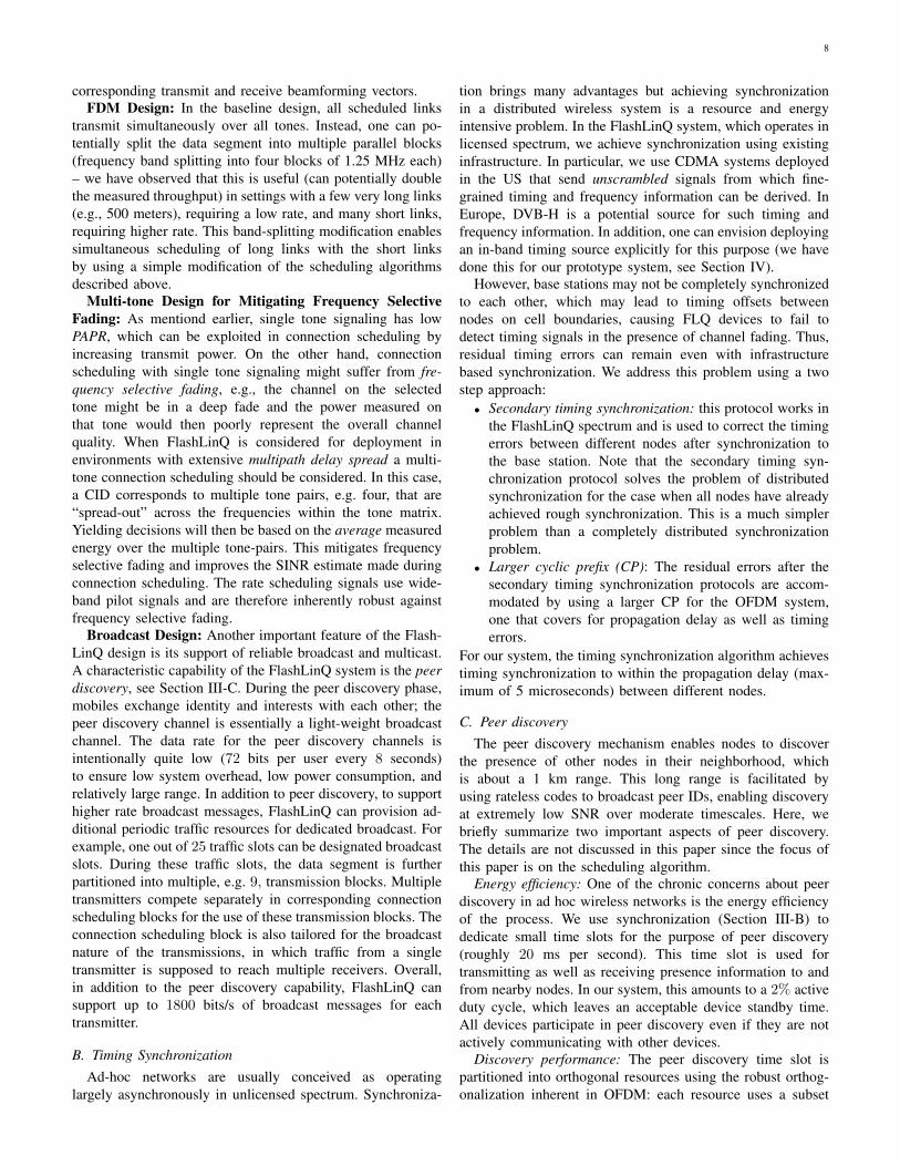
Finally, we compare the CDF of average scheduling latency(scheduling latency = inter-schedule delay, see Figure 16)among all links. Here we see that for the outdoor scenario,WiFi has similar performance as FlashLinQ for most of thelinks, in terms average inter-schedule delay, despite the four-fold bandwidth advantage of WiFi. WiFi has a slight advantage
Fig. 14. Sum throughput comparison
Fig. 15. Rate CDF comparison between WiFi and FlashLinQ for indoor andoutdoor scenarios
over FlashLinQ for users with few interfering neighbors. Thisis because in FlashLinQ, the inter-schedule delay is lowerbounded by the slot size 2ms, while in WiFi, the inter-schedule delay can be much smaller due to larger bandwidthand limited maximum packet size. On the other hand, forthe indoor scenario, we observe a significant improvementwith FlashLinQ on the tail performance. This is due to theinsufficient link protection under the WiFi CSMA protocol,which leads to starvation for some links with a large amountof interfering neighbors.
V. CONCLUSIONS
This paper proposes FlashLinQ – a synchronous peer-to-peer wireless PHY/MAC network architecture for distributedchannel allocation. The key scheduling objective has been todevelop a distributed, channel-aware maximal independent setscheduling algorithm. Our performance study has indicatedthat significant spectral efficiency gains can be obtained over802.11 – and this is key for the licensed spectrum deploymentscenario.
13
Fig. 16. Latency (inter-schedule delay) CDF comparison between WiFi andFlashLinQ for indoor and outdoor scenarios
Finally, we comment that FlashLinQ is by no means op-timal, and that there are several other design optimizationsthat can be made in 802.11 systems to improve performanceas the vast literature in this research area indicates. However,FlashLinQ demonstrates that we can indeed architect, designand implement a fast (timeslot-by-timeslot) channel-aware op-portunistic synchronous system, that accounts for all signalingoverheads and results in gains over a conventional 802.11system. This is of interest, given the considerable interest inslotted-time opportunistic scheduling that is an active area ofresearch today, and indicates that such systems may be a viablealternative to 802.11-based systems.
REFERENCES
[1] X. Wu, S. Tavildar, S. Shakkottai, T. Richardson, J. Li, R. Laroia, andA. Jovicic. Flashlinq: A synchronous distributed scheduler for peer-to-peer ad hoc networks. In Proceedings of the 48th Annual AllertonConference on Communication, Control, and Computing, October 2010.
[2] L. Georgiadis, M. J. Neely, and L. Tassiulas. Resource allocation andcross-layer control in wireless networks. Foundations and Trends inNetworking, 1(1), 2006.
[3] M. Andrews, K. Kumaran, K. Ramanan, A. Stolyar, R. Vijayakumar,and P. Whiting. Scheduling in a queuing system with asynchronouslyvarying service rates. Probab. Eng. Inf. Sci., 18(2):191–217, 2004.
[4] 3rd Generation Partnership Project 2 (3GPP2). Cdma2000 high ratepacket data air interface specification c.s20024-a v2.0. September 2005.
[5] Digital video broadcasting (dvb); transmission system for handheldterminals (dvb-h), etsi en 302 304 v1.1.1 (2004-11).
[6] B. W. Parkinson and J. J. Spilker. The global positioning system: theoryand applications. AIAA (American Institute of Aeronautics & Ast); 1stedition, January 1996.
[7] K. Xu, M. Gerla, and S. Bae. How effective is the IEEE 802.11 RTS/CTShandshake in ad hoc networks? In Proceedings of IEEE GLOBECOM,2002.
[8] F. Ye, S. Yi, and B. Sikdar. Improving spatial reuse of IEEE 802.11based ad hoc networks. In Proceedings of IEEE GLOBECOM, 2003.
[9] X. Lin and N. Shroff. The impact of imperfect scheduling on cross-layer congestion control in wireless networks. IEEE/ACM Trans. Netw.,14(2):302–315, 2006.
[10] S. Sarkar, P. Chaporkar, and K. Kar. Fairness and throughput guaranteeswith maximal scheduling in multi-hop wireless networks. In Proceedingsof WiOpt, pages 286–298, 2006.
[11] L. Bui, A. Eryilmaz, R. Srikant, and X. Wu. Asynchronous congestioncontrol in multi-hop wireless networks with maximal matching-basedscheduling. IEEE/ACM Trans. Netw., 16(4):826–839, 2008.
[12] C. Joo, X. Lin, and N. Shroff. Understanding the capacity region of thegreedy maximal scheduling algorithm in multihop wireless networks.IEEE/ACM Trans. Netw., 17(4):1132–1145, 2009.
[13] S. Sanghavi, L. Bui, and R. Srikant. Distributed link scheduling withconstant overhead. In Proceedings of ACM SIGMETRICS, pages 313–324, 2007.
[14] Libin Jiang and Jean C. Walrand. Convergence and stability ofa distributed csma algorithm for maximal network throughput. InProceedings of IEEE CDC, pages 4840–4845, 2009.
[15] Jian Ni and R. Srikant. Distributed csma/ca algorithms for achievingmaximum throughput in wireless networks. CoRR, abs/0901.2333, 2009.
[16] S. Katti, S. Gollakota, and D. Katabi. Embracing wireless interference:analog network coding. In Proceedings of ACM SIGCOMM, pages 397–408, 2007.
[17] S. Gollakota and D. Katabi. Zigzag decoding: combating hiddenterminals in wireless networks. In Proceedings of ACM SIGCOMM,pages 159–170, 2008.
[18] S. Gollakota, S. Perli, and D. Katabi. Interference alignment andcancellation. In Proceedings of ACM SIGCOMM, pages 159–170, 2009.
[19] P. Bahl, R. Chandra, T. Moscibroda, R. Murty, and M. Welsh. Whitespace networking with wi-fi like connectivity. In Proceedings of ACMSIGCOMM, pages 27–38, 2009.
[20] IEEE 802.11g-2003: http://standards.ieee.org/getieee802/download/802.11g-2003.pdf.
[21] P. Karn. MACA - a new channel access method for packet radio.In ARRI /CRRI, Amateur Radio 9th Computer Networking Conference,September 1990.
[22] V. Bharghavan, A. Demers, S. Shenker, and L. Zhang. MACAW: a mediaaccess protocol for wireless LAN’s. In Proceedings of ACM SIGCOMM,pages 212–225, London, United Kingdom, 1994.
[23] J. Monks, V. Bharghavan, and W. Hwu. A power controlled multipleaccess protocol for wireless packet networks. In Proceedings of IEEEINFOCOM, 2001.
[24] D. Tse and P. Viswanath. Fundamentals of wireless communication.Cambridge University Press, Cambridge, UK, 2005.
[25] Francois Baccelli, Junyi Li, Thomas Richardson, Sundar Subramanian,Xinzhou Wu, and Sanjay Shakkottai. On optimizing csma for wide areaad-hoc networks. In WiOpt, pages 354–359, 2011.
[26] X. Wu, S. Tavildar, S. Shakkottai, T. Richardson, J. Li, R. Laroia, andA. Jovicic. Flashlinq: A synchronous distributed scheduler for peer-to-peer ad hoc networks. Technical Report, 2010.
[27] Dieter J. Cichon and Thomas Krner. Propagation prediction models.COST 231 Final Rep, 1995.
Xinzhou Wu received the B.E. degree from Ts-inghua University, China in 1998, the M.S. andPh.D. degrees from University of Illinois at Urbana-Champaign in 2000 and 2004, all in electrical en-gineering. From 2005 to 2006, he was a Memberof Technical Staff at Flarion Technologies, whichpioneered in OFDMA based cellular technologies.He is currently a Principal Engineer/Manager atQualcomm Research. He currently holds 51 USpatents and has more than 100 pending US patentapplications in the area of wireless communications
and wireless networking. He is a coauthor of the book ”OFDMA MobileBroadband Communications: A Systems Approach” with Dr. Junyi Li andDr. Rajiv Laroia.
Saurabha Tavildar received his B. Tech degreefrom Indian Institute of Technology, Bombay in2001, and M.S. and Ph.D. degrees from Universityof Illinois at Urbana-Champaign in 2003 and 2006,all in electrical engineering. He is currently a SeniorEngineer/Manager at Qualcomm Research. He holds38 US patents and has more than 100 pending USpatent applications in the area of wireless commu-nications and wireless networking.
14
Sanjay Shakkottai (M’02, SM’11) received hisPh.D. from the ECE Department at the Universityof Illinois at Urbana-Champaign in 2002. He iswith The University of Texas at Austin, where he iscurrently a Professor in the Department of Electricaland Computer Engineering, and the Associate Di-rector of Wireless Networking and CommunicationsGroup (WNCG). He received the NSF CAREERaward in 2004. His current research interests includenetwork architectures, algorithms and performanceanalysis for wireless networks, and algorithms for
learning and inference over complex networks.
Tom Richardson (F 2007) is Vice President ofEngineering at Qualcomm’s New Jersey ResearchCenter. He came to Qualcomm through its acqui-sition of Flarion Technologies, a wireless startupspun out of Bell Labs in 2000, where he was VicePresident and Chief Scientist. He was awarded hisPh.D. degree in electrical engineering in 1990 fromMIT after which he worked for 10 years at the BellLabs’ Mathematical Sciences Research Center. Heis coauthor, with Ruediger Urbanke, of ”ModernCoding Theory” a book on iterative coding. He
received the 2002 information theory best paper award and the 2011 IEEEKobayashi award. He is an IEEE fellow and a member of National Academyof Engineering.
Junyi Li is a Vice President of Engineering atQualcomm. He was a key inventor of Flash-OFDM,arguably the first commercially deployed OFDMA-based mobile broadband wireless communicationssystem. He holds over 200 U.S. patents and hasmore than 400 pending patent applications. He was afounding member of Flarion Technologies, a startupacquired by QUALCOMM in 2006. Prior to that,he was with Bell-Labs research in Lucent Technolo-gies. He has a Ph.D. degree in E.E. from PurdueUniversity and an MBA from the Wharton School
at University of Pennsylvania. He is a Fellow of the IEEE. He is a co-author of the book “OFDMA Mobile Broadband Communications” publishedby Cambridge University Press. He received the Outstanding Electrical andComputer Engineers award from Purdue University in 2012.
Rajiv Laroia is currently an Entrepreneur in Res-idence at Charles River Ventures. From February2011 to September 2012 he was Senior Vice Pres-ident and Chief Technology Officer of Sonus Net-works. Prior to that he was Senior Vice Presidentof Technology at Qualcomm Incorporated (Nasdaq:QCOM). In February 2000 he founded Flarion Tech-nologies and was the CTO until it was acquiredby Qualcomm in January of 2006. Rajiv receivedhis Ph.D. and Master’s degrees from the Universityof Maryland, College Park and a Bachelor’s degree
from the Indian Institute of Technology, Delhi, all in electrical engineering.His thesis also contributed to V.34, the ITU voice-band modem internationalstandard. He has coauthored the book ”OFDMA Mobile Broadband Com-munications: A Systems Approach” with Dr. Junyi Li and Dr. Xinzhou Wu.He has over 175 issued patents and more than 200 pending. Rajiv has wonnumerous industry awards. He was inducted to the Innovations Hall of Fame,University of Maryland, College Park, in 2006. In 2007 he received the IITDelhi Distinguished Alumni Award. Rajiv is a Fellow of the IEEE.
Aleksandar Jovicic received his Ph.D. in ECE fromthe University of Illinois at Urbana-Champaign in2007. He is currently with Qualcomm Research NewJersey where he is a Senior Staff Engineer in theSystems group. At Qualcomm Research, Aleksandarhas worked on a number of forward-looking projectsin wireless communication and machine learning.