FLASH - Home - Micross Components AS8F128K32 AS8F128K32 Rev. 2.8 01/10 Micross Components reserves...
22
FLASH AS8F128K32 AS8F128K32 Rev. 2.8 01/10 Micross Components reserves the right to change products or specifications without notice. 1 GENERAL DESCRIPTION The AS8F128K32 is a 4 Megabit CMOS FLASH Memory Module organized as 128K x 32 bits. The AS8F128K32 achieves high speed access (60 to 150 ns), low power consumption and high reliability by employing advanced CMOS memory technology. The device is designed to be programmed in-system with the stan- dard system 5.0V V CC supply. A 12.0V V PP is not required for program or erase operation. The device can also be programmed or erased in standard EPROM programmers. To eliminate bus contention the device has seperate chip enbaled (CEx\), write enable (WEx\) and output enable (OE) controls. The device requires only a single 5.0 volt power supply for both read and write functions. Internally generated and regulated voltages are provided for the program and erase operations. The device is entirely command set compatible with the JEDEC single-power-supply Flash standard. Commands are written to the com- mand register using standard microprocessor write timings. Register contents serve as input to an internal state machine that controls the FEATURES • Fast Access Times: 60, 70, 90, 120 and 150ns • Operation with single 5V (±10%) • Compatible with JEDEC EEPROM command set • Any Combination of Sectors can be Erased • Supports Full Chip Erase • Embedded Erase and Program Algorithms • TTL Compatible Inputs and CMOS Outputs • Hardware Data Protection • Data\ Polling and Toggle Bits • Low Power consumption • Individual Byte Read/ Write Control • Minimum 1,000,000 Program/Erase Cycles per sector guaranteed PIN ASSIGNMENT (Top View) AVAILABLE AS MILITARY SPECIFICATIONS • SMD 5962-94716 • MIL-STD-883 OPTIONS MARKINGS • Timing 60ns -60 70ns -70 90ns -90 120ns -120 150ns -150 • Package Ceramic Quad Flat pack Q No. 703 Ceramic Quad Flat pack Q1 For more products and information please visit our web site at www.micross.com 128K x 32 FLASH FLASH MEMORY ARRAY erase and programming circuitry. Write cycles also internally latch addresses and data needed for the programming and erase operations. Reading data out of the device is similar to reading from other Flash or EPROM devices. Device programming occurs by executing the program command sequence. This invokes the Embedded Program algorithm—an inter- nal algorithm that automatically times the program pulse widths and verifies proper cell margin. Device erasure occurs by executing the erase command sequence. This invokes the Embedded Erase algorithm—an internal algorithm that automatically preprograms the array (if it is not already pro- grammed) before executing the erase operation. During erase, the device automatically times the erase pulse widths and verifies proper cell margin. The host system can detect whether a program or erase operation is complete by reading the I/O7 (Data\ Polling) and I/O6 (toggle) status bits. After a program or erase cycle has been completed, the device is ready to read array data or accept another command. The sector erase architecture allows memory sectors to be erased and reprogrammed without affecting the data contents of other sectors. The device is erased when shipped from the factory. The hardware data protection measures include a low V CC detector automatically inhibits write operations during power transitions. The hardware sector protection feature disables both program and erase operations in any combination of the sectors of memory, and is implemented using standard EPROM programmers. The system can place the device into the standby mode. Power consumption is greatly reduced in this mode. The device electrically erases all bits within a sector simultane- ously via Fowler-Nordheim tunneling. The bytes are programmed one byte at a time using the EPROM programming mechanism of hot electron injection. I/O 0 I/O 1 I/O 2 I/O 3 I/O 4 I/O 5 I/O 6 I/O 7 GND I/O 8 I/O 9 I/O 10 I/O 11 I/O 12 I/O 13 I/O 14 I/O 15 I/O 16 I/O 17 I/O 18 I/O 19 I/O 20 I/O 21 I/O 22 I/O 23 GND I/O 24 I/O 25 I/O 26 I/O 27 I/O 28 I/O 29 I/O 30 I/O 31 Vcc A11 A12 A13 A14 A15 A16 CS1\ OE CS2\ NC WE2\ WE3\ WE4\ NC NC NC NC A0 A1 A2 A3 A4 A5 CS3\ GND CS4\ WE1\ A6 A7 A8 A9 A10 Vcc 68 Lead CQFP (Q & Q1)
Transcript of FLASH - Home - Micross Components AS8F128K32 AS8F128K32 Rev. 2.8 01/10 Micross Components reserves...

FLASHAS8F128K32
AS8F128K32Rev. 2.8 01/10
Micross Components reserves the right to change products or specifi cations without notice.
1
GENERAL DESCRIPTION The AS8F128K32 is a 4 Megabit CMOS FLASH Memory Module organized as 128K x 32 bits. The AS8F128K32 achieves high speed access (60 to 150 ns), low power consumption and high reliability by employing advanced CMOS memory technology. The device is designed to be programmed in-system with the stan-dard system 5.0V VCC supply. A 12.0V VPP is not required for program or erase operation. The device can also be programmed or erased in standard EPROM programmers. To eliminate bus contention the device has seperate chip enbaled (CEx\), write enable (WEx\) and output enable (OE) controls. The device requires only a single 5.0 volt power supply for both read and write functions. Internally generated and regulated voltages are provided for the program and erase operations. The device is entirely command set compatible with the JEDEC single-power-supply Flash standard. Commands are written to the com-mand register using standard microprocessor write timings. Register contents serve as input to an internal state machine that controls the
FEATURES• Fast Access Times: 60, 70, 90, 120 and 150ns• Operation with single 5V (±10%)• Compatible with JEDEC EEPROM command set• Any Combination of Sectors can be Erased• Supports Full Chip Erase• Embedded Erase and Program Algorithms• TTL Compatible Inputs and CMOS Outputs • Hardware Data Protection• Data\ Polling and Toggle Bits• Low Power consumption• Individual Byte Read/ Write Control• Minimum 1,000,000 Program/Erase Cycles per sector guaranteed
PIN ASSIGNMENT (Top View)
AVAILABLE AS MILITARYSPECIFICATIONS• SMD 5962-94716• MIL-STD-883
OPTIONS MARKINGS• Timing 60ns -60 70ns -70 90ns -90 120ns -120 150ns -150
• Package Ceramic Quad Flat pack Q No. 703 Ceramic Quad Flat pack Q1
For more products and informationplease visit our web site at
www.micross.com
128K x 32 FLASHFLASH MEMORY ARRAY
erase and programming circuitry. Write cycles also internally latch addresses and data needed for the programming and erase operations. Reading data out of the device is similar to reading from other Flash or EPROM devices. Device programming occurs by executing the program command sequence. This invokes the Embedded Program algorithm—an inter-nal algorithm that automatically times the program pulse widths and verifi es proper cell margin. Device erasure occurs by executing the erase command sequence. This invokes the Embedded Erase algorithm—an internal algorithm that automatically preprograms the array (if it is not already pro-grammed) before executing the erase operation. During erase, the device automatically times the erase pulse widths and verifi es proper cell margin. The host system can detect whether a program or erase operation is complete by reading the I/O7 (Data\ Polling) and I/O6 (toggle) status bits. After a program or erase cycle has been completed, the device is ready to read array data or accept another command. The sector erase architecture allows memory sectors to be erased and reprogrammed without affecting the data contents of other sectors. The device is erased when shipped from the factory. The hardware data protection measures include a low VCC detector automatically inhibits write operations during power transitions. The hardware sector protection feature disables both program and erase operations in any combination of the sectors of memory, and is implemented using standard EPROM programmers. The system can place the device into the standby mode. Power consumption is greatly reduced in this mode. The device electrically erases all bits within a sector simultane-ously via Fowler-Nordheim tunneling. The bytes are programmed one byte at a time using the EPROM programming mechanism of hot electron injection.
I/O 0I/O 1I/O 2I/O 3I/O 4I/O 5I/O 6I/O 7GNDI/O 8I/O 9
I/O 10I/O 11I/O 12I/O 13I/O 14I/O 15
I/O 16I/O 17I/O 18I/O 19I/O 20I/O 21I/O 22I/O 23GNDI/O 24I/O 25I/O 26I/O 27I/O 28I/O 29I/O 30I/O 31
Vcc
A11
A12
A13
A14
A15
A16
CS
1\ OE
CS
2\ NC
WE
2\W
E3\
WE
4\ NC
NC
NC
NC
A0
A1
A2
A3
A4
A5
CS
3\G
ND
CS
4\W
E1\
A6
A7
A8
A9
A10
Vcc
68 Lead CQFP (Q & Q1)

FLASHAS8F128K32
AS8F128K32Rev. 2.8 01/10
Micross Components reserves the right to change products or specifi cations without notice.
2
FUNCTIONAL BLOCK DIAGRAM
PIN CONFIGURATION
PIN DESCRIPTIONA0 - A16 AddressesI/O0 - I/O31 Input/OutputCEx\ Chip EnableOE\ Output EnableWEx\ Write Enable
VCC 5.0V Power Supply
GND Device GroundNC No Connect
LOGIC SYMBOL
x = 1, 2, 3 or 4

FLASHAS8F128K32
AS8F128K32Rev. 2.8 01/10
Micross Components reserves the right to change products or specifi cations without notice.
3
DEVICE BUS OPERATIONSNOTE: All device/algorithm descriptions contained in this data sheet reference each individual die. This section describes the requirements and use of the device bus operations, which are initiated through the inter-nal command register. The command register itself does not occupy any addressable memory location. The register is composed of latches that store the commands, along with the address and data information needed to execute the command. The contents of the register serve as inputs to the internal state machine. The state machine outputs dictate the function of the device. The appropriate device bus operations table lists the inputs and control levels required, and the resulting output. The following subsections describe each of these operations in further detail.
Requirements for Reading Array Data To read array data from the outputs, the system must drive the CEx\ and OE\ pins to VIL. CEx\ is the power control and selects the device. OE\ is the output control and gates array data to the output pins. WEx\ should remain at VIH. The internal state machine is set for reading array data upon device power-up. This ensures that no spurious altera-tion of the memory content occurs during the power transition. No command is necessary in this mode to obtain array data. Standard microprocessor read cycles that assert valid addresses on the device address inputs produce valid data on the device data outputs. The device remains enabled for read access until
the command register contents are altered. See “Reading Array Data” for more information. Refer to the AC Read Operations table for timing specifi cations and to the Read Operations Timings diagram for the timing wave-forms. ICC1 in the DC Characteristics table represents the active current specifi cation for reading array data.
Writing Commands/Command Sequences To write a command or command sequence (which in-cludes programming data to the device and erasing sectors of memory), the system must drive WEx\ and CEx\ to VIL, and OE\ to VIH. An erase operation can erase one sector, multiple sectors, or the entire device. The Sector Address Tables indicate the address space that each sector occupies. A “sector address” consists of the address bits required to uniquely select a sector. See the “Command Defi nitions” section for details on erasing a sector or the entire chip. After the system writes the autoselect command se-quence,the device enters the autoselect mode. The system can then read autoselect codes from the internal register (which is separate from the memory array) on I/O31–I/O0. Standard read cycle timings apply in this mode. Refer to the “Autoselect Mode” and “Autoselect Command Sequence” sections for more information. ICC2 in the DC Characteristics table represents the active current specifi cation for the write mode. The “AC Characteristics” section contains timing specifi cation tables
TABLE 1: Device Bus Operations1
OPERATION CEx\ OE\ WEx\ADRESSES
(A16:A0)I/O0 - I/O31
Read L L H AIN DOUT
Write L H L AIN DIN
Standby VCC ± 0.5V X X X High-Z
Output Disable L H H X High-Z
Hardware Reset X X X X High-Z
Temporary Sector Unprotect X X X AIN DIN
LEGEND:L = Logic Low = VIL, H = Logic High = VIH, VID = 12.0 ± 0.5 V, X = Don’t Care, AIN = Addresses In, DIN = Data In, DOUT = Data Out
NOTES:1. The sector protect and sector unprotect functions must be implemented via programming equipment. See the “Sector Protection/Unprotection” section.

FLASHAS8F128K32
AS8F128K32Rev. 2.8 01/10
Micross Components reserves the right to change products or specifi cations without notice.
4
Program and Erase Operation Status During an erase or program operation, the system may check the status of the operation by reading the status bits on I/O31–I/O0. Standard read cycle timings and ICC read specifi ca-tions apply. Refer to “Write Operation Status” for more informa-tion, and to each AC Characteristics section in the appropriate data sheet for timing diagrams.
Standby Mode When the system is not reading or writing to the device, it can place the device in the standby mode. In this mode, current consumption is greatly reduced, and the outputs are placed in the high impedance state, independent of the OE\ input. The device enters the CMOS standby mode when the CEx\ pin is held at VCC ± 0.5 V. (Note that this is a more restricted voltage range than VIH.) The device enters the TTL standby mode when CEx\ is held at VIH. The device requires the stan-dard access time (tCE) before it is ready to read data. If the device is deselected during erasure or programming, the device draws active current until the operation is completed. ICC3 in the DC Characteristics tables represents the standby current specifi cation.
Output Disable Mode When the OE\ input is at VIH, output from the device is disabled. The output pins are placed in the high impedance state.
Autoselect Mode The autoselect mode provides manufacturer and device identification, and sector protection verification, through identifi er codes output on I/O31–I/O0. This mode is primarily intended for programming equipment to automatically match a device to be programmed with its corresponding programming algorithm. However, the autoselect codes can also be accessed in-system through the command register. When using programming equipment, the autoselect mode requires VID (11.5 V to 12.5 V) on address pin A9. Address pins A6, A1, and A0 must be as shown in Autoselect Codes (High Voltage Method) table. In addition, when verifying sector protection, the sector address must appear on the appropriate highest order address bits. Refer to the corresponding Sector Address Tables. The Command Defi nitions table shows the remaining address bits that are don’t care. When all necessary bits have been set as required, the programming equipment may then read the corresponding identifi er code on I/O31– I/O0. To access the autoselect codes in-system, the host system can issue the autoselect command via the command register, as shown in the Command Defi nitions table. This method does not require VID. See “Command Defi nitions” for details on using the autoselect mode.
TABLE 2: Sector Addresses Table (Each Byte)SECTOR A16 A15 A14 ADDRESS RANGE
SA0 0 0 0 00000h - 03FFFhSA1 0 0 1 04000h - 07FFFhSA2 0 1 0 08000h - 0BFFFhSA3 0 1 1 0C000h - 0FFFFhSA4 1 0 0 10000h - 13FFFhSA5 1 0 1 14000h - 17FFFhSA6 1 1 0 18000h - 1BFFFhSA7 1 1 1 1C000h - 1FFFFh

FLASHAS8F128K32
AS8F128K32Rev. 2.8 01/10
Micross Components reserves the right to change products or specifi cations without notice.
5
Sector Protection/Unprotection The hardware sector protection feature disables both program and erase operations in any sector. The hardware sector unprotection feature re-enables both program and erase operations in previously protected sectors. Sector protection/unprotection must be implemented us-ing programming equipment. The procedure requires a high voltage (VID) on address pin A9 and the control pins. The device is shipped with all sectors unprotected. It is possible to determine whether a sector is protected or un-protected. See “Autoselect Mode” for details.
Hardware Data Protection The command sequence requirement of unlock cycles for programming or erasing provides data protection against inadvertent writes (refer to the Command Defi nitions table). In addition, the following hardware data protection measures prevent accidental erasure or programming, which might otherwise be caused by spurious system level signals during VCC power-up and power-down transitions, or from system noise.
Low VCC Write Inhibit When VCC is less than VLKO, the device does not accept any write cycles. This protects data during VCC power-up and power-down. The command register and all internal program/erase circuits are disabled, and the device resets. Subsequent writes are ignored until VCC is greater than VLKO. The system must provide the proper signals to the control pins to prevent unintentional writes when VCC is greater than VLKO.
Write Pulse “Glitch” Protection Noise pulses of less than 5 ns (typical) on OE\, CEx\ or WEx\ do not initiate a write cycle.
Logical InhibitWrite cycles are inhibited by holding any one of OE\ = VIL, CEx\ = VIH or WEx\ = VIH. To initiate a write cycle, CEx\ and WEx\ must be a logical zero while OE\ is a logical one.
Power-Up Write InhibitIf WEx\ = CEx\ = VIL and OE\ = VIH during power up, the device does not accept commands on the rising edge of WEx\. The internal state machine is automatical ly reset to reading array data on power-up.
TABLE 3: Autoselect Codes (High Voltage Method)
DESCRIPTION CEx\ OE\ WEx\A16 to
A14
A13 to
A10A9
A8 to A7
A6A5 to A2
A1 A0
I/O0 to I/O7 I/O8 to I/O15 I/O16 to I/O23 I/O24 to I/O31
Manufacturer ID: AMD L L H X X VID X L X L L 01h
Device ID: AM29F010B L L H X X VID X L X L H 20h
01h (protected)
00h (unprotected)Sector Protection Verification
L L H SA X VID X L X H L
LEGEND:L = Logic Low = VIL, H = Logic High = VIH, SA = Sector Address, X = Don’t care.
FLASHAS8F128K32
AS8F128K32Rev. 2.8 01/10
Micross Components reserves the right to change products or specifi cations without notice.
6
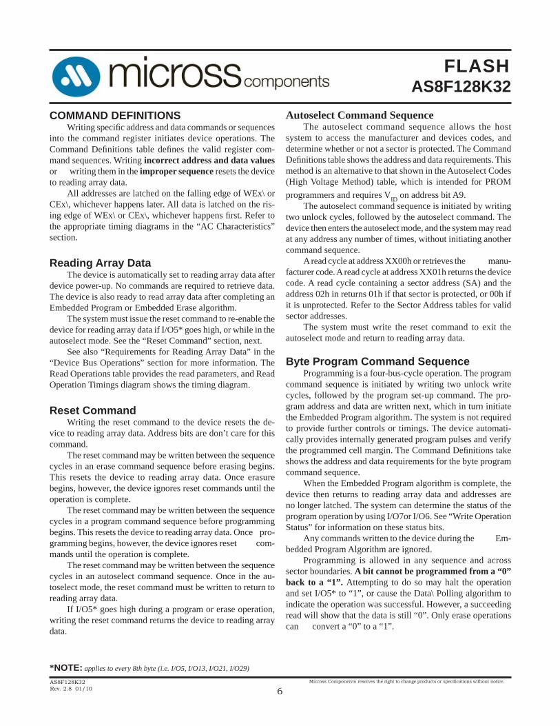
COMMAND DEFINITIONS Writing specifi c address and data commands or sequences into the command register initiates device operations. The Command Defi nitions table defi nes the valid register com-mand sequences. Writing incorrect address and data values or writing them in the improper sequence resets the device to reading array data. All addresses are latched on the falling edge of WEx\ or CEx\, whichever happens later. All data is latched on the ris-ing edge of WEx\ or CEx\, whichever happens fi rst. Refer to the appropriate timing diagrams in the “AC Characteristics” section.
Reading Array Data The device is automatically set to reading array data after device power-up. No commands are required to retrieve data. The device is also ready to read array data after completing an Embedded Program or Embedded Erase algorithm. The system must issue the reset command to re-enable the device for reading array data if I/O5* goes high, or while in the autoselect mode. See the “Reset Command” section, next. See also “Requirements for Reading Array Data” in the “Device Bus Operations” section for more information. The Read Operations table provides the read parameters, and Read Operation Timings diagram shows the timing diagram.
Reset Command Writing the reset command to the device resets the de-vice to reading array data. Address bits are don’t care for this command. The reset command may be written between the sequence cycles in an erase command sequence before erasing begins. This resets the device to reading array data. Once erasure begins, however, the device ignores reset commands until the operation is complete. The reset command may be written between the sequence cycles in a program command sequence before programming begins. This resets the device to reading array data. Once pro-gramming begins, however, the device ignores reset com-mands until the operation is complete. The reset command may be written between the sequence cycles in an autoselect command sequence. Once in the au-toselect mode, the reset command must be written to return to reading array data. If I/O5* goes high during a program or erase operation, writing the reset command returns the device to reading array data.
Autoselect Command Sequence The autoselect command sequence allows the host system to access the manufacturer and devices codes, and determine whether or not a sector is protected. The Command Defi nitions table shows the address and data requirements. This method is an alternative to that shown in the Autoselect Codes (High Voltage Method) table, which is intended for PROM programmers and requires VID on address bit A9. The autoselect command sequence is initiated by writing two unlock cycles, followed by the autoselect command. The device then enters the autoselect mode, and the system may read at any address any number of times, without initiating another command sequence. A read cycle at address XX00h or retrieves the manu-facturer code. A read cycle at address XX01h returns the device code. A read cycle containing a sector address (SA) and the address 02h in returns 01h if that sector is protected, or 00h if it is unprotected. Refer to the Sector Address tables for valid sector addresses. The system must write the reset command to exit the autoselect mode and return to reading array data.
Byte Program Command Sequence Programming is a four-bus-cycle operation. The program command sequence is initiated by writing two unlock write cycles, followed by the program set-up command. The pro-gram address and data are written next, which in turn initiate the Embedded Program algorithm. The system is not required to provide further controls or timings. The device automati-cally provides internally generated program pulses and verify the programmed cell margin. The Command Defi nitions take shows the address and data requirements for the byte program command sequence. When the Embedded Program algorithm is complete, the device then returns to reading array data and addresses are no longer latched. The system can determine the status of the program operation by using I/O7or I/O6. See “Write Operation Status” for information on these status bits. Any commands written to the device during the Em-bedded Program Algorithm are ignored. Programming is allowed in any sequence and across sector boundaries. A bit cannot be programmed from a “0” back to a “1”. Attempting to do so may halt the operation and set I/O5* to “1”, or cause the Data\ Polling algorithm to indicate the operation was successful. However, a succeeding read will show that the data is still “0”. Only erase operations can convert a “0” to a “1”.
*NOTE: applies to every 8th byte (i.e. I/O5, I/O13, I/O21, I/O29)

FLASHAS8F128K32
AS8F128K32Rev. 2.8 01/10
Micross Components reserves the right to change products or specifi cations without notice.
7
Chip Erase Command Sequence Chip erase is a six-bus-cycle operation. The chip erase command sequence is initiated by writing two unlock cycles, followed by a set-up command. Two additional unlock write cycles are then followed by the chip erase command, which in turn invokes the Embedded Erase algorithm. The device does not require the system to preprogram prior to erase. The Embedded Erase algorithm automatically preprograms and verifi es the entire memory for an all zero data pattern prior to electrical erase. The system is not required to provide any controls or timings during these operations. The Command Defi nitions table shows the address and data requirements for the chip erase command sequence. Any commands written to the chip during the Embedded Erase algorithm are ignored. The system can determine the status of the erase op-eration by using I/O7 or I/O6. See “Write Operation Status” for information on these status bits. When the Embedded Erase algorithm is complete, the device returns to reading array data and addresses are no longer latched. Figure 2 illustrates the algorithm for the erase operation. See the Erase/Program Operations tables in “AC Char-acteristics” for parameters, and to the Chip/Sector Erase Opera-tion Timings for timing waveforms.
Sector Erase Command Sequence Sector erase is a six bus cycle operation. The sector erase command sequence is initiated by writing two unlock cycles, followed by a set-up command. Two additional unlock write cycles are then followed by the address of the sector to be erased, and the sector erase command. The Command Defi ni-tions table shows the address and data requirements for the sector erase command sequence. The device does not require the system to preprogram the memory prior to erase. The Embedded Erase algorithm automatically programs and verifi es the sector for an all zero data pattern prior to electrical erase. The system is not required to provide any controls or timings during these operations. After the command sequence is written, a sector erase time-out of 50 ms begins. During the time-out period, additional sector addresses and sector erase commands may be written. Loading the sector erase buffer may be done in any sequence, and the number of sectors may be from one sector to all sec-tors. The time between these additional cycles must be less than 50 ms, otherwise the last address and command might not be accepted, and erasure may begin. It is recommended that processor interrupts be disabled during this time to ensure all commands are accepted. The interrupts can be re-enabled after the last Sector Erase command is written. If the time between
additional sector erase commands can be assumed to be less than 50 ms, the system need not monitor I/O3*. Any command during the time-out period resets the device to reading array data. The system must rewrite the command sequence and any additional sector addresses and commands. The system can monitor I/O3* to determine if the sector erase timer has timed out. (See the “I/O3*: Sector Erase Timer” section.) The time-out begins from the rising edge of the fi nal WE# pulse in the command sequence. Once the sector erase operation has begun, all other com-mands are ignored. When the Embedded Erase algorithm is complete, the device returns to reading array data and addresses are no lon-ger latched. The system can determine the status of the erase operation by using I/O7 or I/O6. Refer to “Write Operation Status” for information on these status bits. Figure 2 illustrates the algorithm for the erase operation. Refer to the Erase/Program Operations tables in the “AC Characteristics” section for parameters, and to the Sector Erase Operations Timing diagram for timing waveforms.
FIGURE 1: Program Operation
NOTE: See the appropriate Command Defi nitions table for program com-mand sequence.*NOTE: applies to every 8th byte (i.e. I/O3, I/O11, I/O19, I/O27)

FLASHAS8F128K32
AS8F128K32Rev. 2.8 01/10
Micross Components reserves the right to change products or specifi cations without notice.
8
Addr Data8 Addr Data8 Addr Data8 Addr Data8 Addr Data8 Addr Data8
1 RA RD
3 555 AA 2AA 55 555 F0
Manufacturer ID 4 555 AA 2AA 55 555 90 XX00 1Device ID 4 555 AA 2AA 55 555 90 XX01 20
555 2AA 555 00
555 2AA 555 01
4 555 AA 2AA 55 555 A0 PA PD6 555 AA 2AA 55 555 80 555 AA 2AA 55 555 106 555 AA 2AA 55 555 80 555 AA 2AA 55 SA 30
90(SA)X02
Chip EraseSector Erase
Reset5
Autoselect6
Sector Protect Verify7
Read4
Program
FIFTH SIXTH
4 AA 55
BUS CYCLES2,3
CY
CL
ES
COMMAND SEQUENCE1 FIRST SECOND THIRD FOURTH
TABLE 4: Command Defi nitions (Applies to each device8)
LEGEND:X = Don’t careRA = Address of the memory location to be read.RD = Data read from location RA during read operation.PA = Address of the memory location to be programmed.Addresses latch on the falling edge of the WEx\ or CEx\ pulse, whichever happens later.PD = Data to be programmed at location PA. Data latches on the rising edge of WEx\ or CEx\ pulse, whichever happens fi rst.SA = Address of the sector to be verifi ed (in autoselect mode) or erased. Ad-dress bits A16–A14 uniquely select any sector.
FIGURE 2: Erase Operation
NOTE: 1. See the appropriate Command Defi nitions table for program command sequence.2. See "I/O3: Sector Erase Timer" for more information.
NOTES:1. See Table 1 for description of bus operations.2. All values are in hexadecimal.3. Except when reading array or autoselect data, all command bus cycles are write operations.4. No unlock or command cycles required when reading array data.5. The Reset command is required to return to reading array data when device is in the autoselect mode, or if I/O5 goes high (while the device is providing status data).6. The fourth cycle of the autoselect command sequence is a read operation.7. The data is 00h for an unprotected sector and 01h for a protected sector. See “Autoselect Command Sequence” for more information.8. Data shown for each respective byte I/O31-I/O24, I/O25-I/O16, I/O15-I/O8, I/O7-I/O0.

FLASHAS8F128K32
AS8F128K32Rev. 2.8 01/10
Micross Components reserves the right to change products or specifi cations without notice.
9
WRITE OPERATION STATUS The device provides several bits to determine the status of a write operation: I/O3, I/O5, I/O6, and I/O7. Table 5 and the following subsections describe the functions of these bits. I/O7 and I/O6 each offer a method for determining whether a program or erase operation is complete or in progress. These three bits are discussed fi rst.
I/O7: Data\ Polling The Data\ Polling bit, I/O7*, indicates to the host system whether an Embedded Algorithm is in progress or completed. Data\ Polling is valid after the rising edge of the fi nal WEx\ pulse in the program or erase command sequence. During the Embedded Program algorithm, the device outputs on I/O7* the complement of the datum programmed to I/O7*. When the Embedded Program algorithm is com-plete, the device outputs the datum programmed to I/O7*. The system must provide the program address to read valid status information on I/O7*. If a program address falls within a protected sector, Data\ Polling on I/O7* is active for approximately 2 ms, then the device returns to reading array data. During the Embedded Erase algorithm, Data\ Polling produces a “0” on I/O7*. When the Embedded Erase algorithm is complete, Data\ Polling produces a “1” on I/O7*. This is analogous to the complement/true datum output described for the Embedded Program algorithm: the erase function changes all the bits in a sector to “1”; prior to this, the device outputs the “complement,” or “0.” The system must provide an address within any of the sectors selected for erasure to read valid status information on I/O7*. After an erase command sequence is written, if all sectors selected for erasing are protected, Data\ Polling on I/O7* is active for approximately 100 ms, then the device returns to reading array data. If not all selected sectors are protected, the Embedded Erase algorithm erases the unprotected sectors, and ignores the selected sectors that are protected. When the system detects I/O7* has changed from the complement to true data, it can read valid data at I/O7– I/O0 on the following read cycles. This is because I/O7* may change asynchronously with I/O0–I/O6 while Output Enable (OE\) is asserted low. The Data\ Polling Timings (During Embedded Algorithms) fi gure in the “AC Characteristics” section il-lustrates this. Table 5 shows the outputs for Data\ Polling on I/O7*. Figure 3 shows the Data\ Polling algorithm.
FIGURE 3: Data\ Polling Algorithm
NOTES:1. VA = Valid address for programming. During a sector erase operation, a valid address is an address within any sector selected for erasure. During chip erase, a valid address is any non-protected sector address.2. I/O7 should be rechecked even if I/O5 = “1” because I/O7 may change simultaneously with I/O5.
*NOTE: applies to every 8th byte.
*
*
*

FLASHAS8F128K32
AS8F128K32Rev. 2.8 01/10
Micross Components reserves the right to change products or specifi cations without notice.
10
I/O6: Toggle Bit I Toggle Bit I on I/O6 indicates whether an Embedded Program or Erase algorithm is in progress or complete. Toggle Bit I may be read at any address, and is valid after the rising edge of the fi nal WEx\ pulse in the command sequence (prior to the program or erase operation), and during the sector erase time-out. During an Embedded Program or Erase algorithm op-eration, successive read cycles to any address cause I/O6 to toggle. (The system may use either OE\ or CEx\ to control the read cycles.) When the operation is complete, I/O6 stops toggling. After an erase command sequence is written, if all sectors selected for erasing are protected, I/O6 toggles or approxi-mately 100 ms, then returns to reading array data. If not all selected sectors are protected, the Embedded Erase algorithm erases the unprotected sectors, and ignores the selected sectors that are protected. If a program address falls within a protected sector, I/O6 toggles for approximately 2 ms after the program command sequence is written, then returns to reading array data. The Write Operation Status table shows the outputs for Toggle Bit I on I/O6. Refer to Figure 4 for the toggle bit algorithm, and to the Toggle Bit Timings fi gure in the “AC Characteristics” section for the timing diagram.
Reading Toggle Bit I/O6 Refer to Figure 4 for the following discussion. Whenever the system initially begins reading toggle bit status, it must read I/O7–I/O0 at least twice in a row to determine whether a toggle bit is toggling. Typically, a system would note and store the value of the toggle bit after the fi rst read. After the second read, the system would compare the new value of the toggle bit with the fi rst. If the toggle bit is not toggling, the device has completed the program or erase operation. The system can read array data on I/O7–I/O0 on the following read cycle. However, if after the initial two read cycles, the system determines that the toggle bit is still toggling, the system also should note whether the value of I/O5 is high (see the sec-tion on I/O5). If it is, the system should then determine again whether the toggle bit is toggling, since the toggle bit may have stopped toggling just as I/O5 went high. If the toggle bit is no longer toggling, the device has successfully completed the program or erase operation. If it is still toggling, the device did not complete the operation successfully, and the system must write the reset command to return to reading array data. The remaining scenario is that the system initially de-termines that the toggle bit is toggling and I/O5 has not gone high. The system may continue to monitor the toggle bit and
I/O5 through successive read cycles, determining the status as described in the previous paragraph. Alternatively, it may choose to perform other system tasks. In this case, the system must start at the beginning of the algorithm when it returns to determine the status of the operation (top of Figure 4).
FIGURE 4: Toggle Bit Algorithm
NOTES:1. Read toggle bit twice to determine whether or not it is toggling. See text.2. Recheck toggle bit because it may stop toggling as I/O5 changes to “1”. See text.
*
*NOTE: applies to every 8th byte.

FLASHAS8F128K32
AS8F128K32Rev. 2.8 01/10
Micross Components reserves the right to change products or specifi cations without notice.
11
I/O5: Exceeded Timing Limits I/O5* indicates whether the program or erase time has exceeded a specifi ed internal pulse count limit. Under these conditions I/O5* produces a “1.” This is a failure condition that indicates the program or erase cycle was not successfully completed. The I/O5* failure condition may appear if the system tries to program a “1” to a location that is previously programmed to “0.” Only an erase operation can change a “0” back to a “1.” Under this condition, the device halts the operation, and when the operation has exceeded the timing limits, I/O5* produces a “1.” Under both these conditions, the system must issue the reset command to return the device to reading array data.
I/O3: Sector Erase Timer After writing a sector erase command sequence, the system may read I/O3* to determine whether or not an erase
operation has begun. (The sector erase timer does not apply to the chip erase command.) If additional sectors are selected for erasure, the entire timeout also applies after each additional sector erase command. When the time-out is complete, I/O3* switches from “0” to “1.” The system may ignore I/O3* if the system can guarantee that the time between additional sector erase commands will always be less than 50 ms. See also the “Sector Erase Command Sequence” section. After the sector erase command sequence is written, the system should read the status on I/O7* (Data\ Polling) or I/O6 (Toggle Bit I) to ensure the device has accepted the command sequence, and then read I/O3. If I/O3 is “1”, the internally con-trolled erase cycle has begun; all further commands are ignored until the erase operation is complete. If I/O3 is “0”, the device will accept additional sector erase commands. To ensure the command has been accepted, the system software should check the status of I/O3 prior to and following each subsequent sector erase command. If I/O3 is high on the second status check, the last command might not have been accepted. Table
TABLE 5: Write Operation StatusOPERATION I/O71,* I/O6* I/O52,* I/O3*
Embedded Program Algorithm I/O7\ Toggle 0 N/AEmbedded Erase Algorithm 0 Toggle 0 1
NOTES: *applies to every 8th byte1. I/O7 requires a valid address when reading status information. Refer to the appropriate subsection for further details.2. I/O5 switches to ‘1’ when an Embedded Program or Embedded Erase operation has exceeded the maximum timing limits. See “I/O5: Exceeded Timing Limits” for more information.
*Stresses greater than those listed under "Absolute Maximum Ratings" may cause permanent damage to the device. This is a stress rating only and functional operation of the device at these or any other conditions above those indicated in the operation section of this specifi cation is not implied. Exposure to absolute maximum rating conditions for extended periods may affect reliability.
ABSOLUTE MAXIMUM RATINGS*Voltage with respect to Ground, VCC
1.............-2.0V to +7.0VVoltage with respect to Ground, A9 2................-2.0V to +14VVoltage with respect to Ground, All other pins 1-2.0V to +7.0VShort-circuit output current..........................................200mAAmbient Temperature with power Applied.....-55°C to 125°CStorage temperature range................................-65°C to 150°CNOTES:1. Minimum DC voltage on input or I/O pin is –0.5 V. During voltage transitions, inputs may overshoot VSS to –2.0 V for periods of up to 20 ns. See Figure 5. Maximum DC on input and I/O pins is VCC + 0.5 V. During voltage transitions, input and I/O pins may overshoot to VCC + 2.0 V for periods up to 20 ns. See Figure 6.2. Minimum DC input voltage on A9 pin is –0.5V. During voltage transitions, A9 pins may overshoot VSS to –2.0 V for periods of up to 20 ns. See Figure 5. Maximum DC input voltage on A9 is +12.5 V which may overshoot to 14V for periods up to 20 ns.3. No more than one output shorted at a time. Duration of the short circuit should not be greater than one second.
FIGURE 5: Maximum Negative Overshoot FIGURE 6: Maximum Positive Overshoot

FLASHAS8F128K32
AS8F128K32Rev. 2.8 01/10
Micross Components reserves the right to change products or specifi cations without notice.
12
DC CHARACTERISTICSSYM CONDITION MIN MAX UNIT
ILI VIN = VSS to VCC, VCC = VCCMax ±10 µA
ILIT VCC = VCCMax, A9 = 12.5V 200 µA
ILO VOUT = VSS to VCC, VCC = VCCMax ±10 µA
ICC1 CEx\ = VIL, OE\ = VIH, VCC = VCCMax, f = 5MHz 140 mA
ICC2 CEx\ = VIL, OE\ = VIH, VCC = VCCMax, f = 5MHz 200 mA
TTL/NMOS ICC3 VCC = VCCMax, CEx\ and OE\ = VIH, f = 5MHz 6.5 mA
CMOS ICC3 VCC = VCCMax, CEx\ = VCC ± 0.3V, OE\ = VIH 2 mA
VIL -0.5 0.8 V
VIH 2.0 VCC + 0.5 V
VID VCC = 5.0V 11.5 12.5 V
VOL IOL = 12mA, VCC = VCCMin 0.45 V
TTL/NMOS VOH IOH = -2.5mA, VCC = VCCMin 2.4 V
VOH1 IOH = -2.5mA, VCC = VCCMin 0.85 VCC V
VOH2 IOH = -100µA, VCC = VCCMin VCC -0.4 V
VLKO 3.2 4.2 V
Voltage for Autoselect and Temporary Sector Unprotect
Output Low Voltage
Low VCC Lock-out Voltage
CMOS
VCC Standby Current
Output High Voltage
PARAMETER
Input Load Current
A9 Input Load Current
Output Leakage Current
VCC Active Current1
VCC Active Current2,3
Input Low Voltage
Input High Voltage
NOTES:1. The ICC current listed is typically less than 8 mA/MHz, with OE\ at VIH.2. ICC active while Embedded Program or Embedded Erase Algorithm is in progress.3. Not 100% tested.
FIGURE 7: Test Setup
NOTE: Diodes are IN3064 or equivalent.
TABLE 6: Test Specifi cationsCONDITION ALL SPEEDS UNIT
Output Load
Output Load Capacitiance, CL
(Including jig capacitance)50 pF
Input Rise and Fall Times 5 nsInput Pulse Levels 0.0 - 0.3 VInput timing measurement reference levels
1.5 V
Output timing measurement reference levels
1.5 V
1 TTL Gate

FLASHAS8F128K32
AS8F128K32Rev. 2.8 01/10
Micross Components reserves the right to change products or specifi cations without notice.
13
AC CHARACTERISTICS
JEDEC Standard
Read Cycle Time1 tAVAV tRC Min 60 70 90 120 150 ns
Address to Output Delay tAVQV tACCCEx\ = VIL
OE\ = VILMax 60 70 90 120 150 ns
Chip Enable to Output Delay tELQV tCE Max 60 70 90 120 150 ns
Output Enable to Output Delay tGLQV tOE Max 30 35 40 50 55 ns
Chip Enable to Output High Z1,2 tEHQZ tDF Max 20 20 25 30 35 ns
Output Enable to Output High Z1,2 tGHQZ tDF Max 20 20 25 30 35 ns
Read Min ns
Toggle and Data Polling
Min ns
Output Hold Time From Addresses CEx\ or OE\, Whichever Comes First
tAXQX tOH Min ns
Write Cycle Time1 tAVAV tWC Min 60 70 90 120 150 ns
Address Setup Time tAVWL tAS Min ns
Address Hold Time tWLAX tAH Min 45 45 45 50 50 ns
Data Setup Time tDVWH tDS Min 30 30 45 50 50 ns
Data Hold Time tWHDX tDH Min ns
Read Recover Time Before Write (OE\ High to WEx\ Low)
tGHWL tGHWL Min ns
CEx\ Setup Time tELWL tCS Min ns
CEx\ Hold Time tWHEH tCH Min ns
Write Pulse Width tWLWH tWP Min 30 35 45 50 50 ns
Write Pulse Width High tWHWL tWPH Min ns
Byte Programming Operation4 tWHWH1 tWHWH1 TYP µs
Sector Erase Operation4 tWHWH2 tWHWH2 TYP sec
VCC Setup Time1 tVCS Min µs
-150SYMBOL
TEST SETUPPARAMETER -60 UNIT
Output Enable Hold Time1
Read-Only Operations
tOEH10
0
-70 -90 -120
0
0
0
0
Erase and Program Operations
1.0
50
0
0
20
14
NOTES:1. Not 100% tested.2. Output Driver Disable Time.3. See Figure 7 and Table 6 for test specifi cations.4. See the “Erase and Programming Performance” section for more information.
FLASHAS8F128K32
AS8F128K32Rev. 2.8 01/10
Micross Components reserves the right to change products or specifi cations without notice.
14
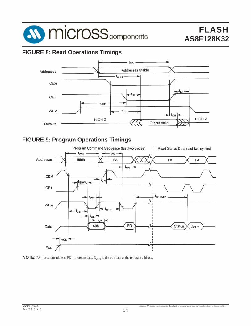
FIGURE 8: Read Operations Timings
FIGURE 9: Program Operations Timings
NOTE: PA = program address, PD = program data, DOUT is the true data at the program address.

FLASHAS8F128K32
AS8F128K32Rev. 2.8 01/10
Micross Components reserves the right to change products or specifi cations without notice.
15
FIGURE 10: Chip/Sector Erase Operations Timings
NOTE: SA = sector address (for Sector Erase), VA = Valid Address for reading status data (see “Write Operation Status”).
FIGURE 11: Data\ Polling Timings (During Embedded Algorithms)
NOTES: VA = Valid address. Illustration shows fi rst status cycle after command sequence, last status read cycle, and array data read cycle.*applies to every 8th byte.
2AAh

FLASHAS8F128K32
AS8F128K32Rev. 2.8 01/10
Micross Components reserves the right to change products or specifi cations without notice.
16
FIGURE 12: Toggle Bit Timings (During Embedded Algorithms)
NOTES: VA = Valid address; not required for I/O6. Illustration shows fi rst two status cycle after command sequence, last status readcycle, and array data read cycle.
AC CHARACTERISTICS: Erase and Program Operations, Alternate CEx\ Controlled Writes
JEDEC Standard
Write Cycle Time1 tAVAV tWC Min 60 70 90 120 150 ns
Address Setup Time tAVEL tAS Min ns
Address Hold Time tELAX tAH Min 45 45 45 50 50 ns
Data Setup Time tDVEH tDS Min 30 30 45 50 50 ns
Data Hold Time tEHDX tDH Min ns
Output Enable Setup Time1 tOES Min ns
Read Recover Time Before Write tGHEL tGHEL Min ns
WEx\ Setup Time tEHWH tWS Min ns
WEx\ Hold Time tEHWH tWH Min ns
CEx\ Pulse Width tELEH tCP Min 30 35 45 50 50 ns
CEx\ Pulse Width High tEHEL tCPH Min ns
Byte Programming Operation2 tWHWH1 tWHWH1 TYP µs
Chip/Sector Erase Operation2 tWHWH2 tWHWH2 TYP sec1.0
0
0
20
14
0
0
0
0
UNIT-70 -90 -120 -150SYMBOL
PARAMETER -60DESCRIPTION
NOTES:1. Not 100% tested.2. See the “Erase and Programming Performance” section for more information.
*applies to every 8th byte.
FLASHAS8F128K32
AS8F128K32Rev. 2.8 01/10
Micross Components reserves the right to change products or specifi cations without notice.
17
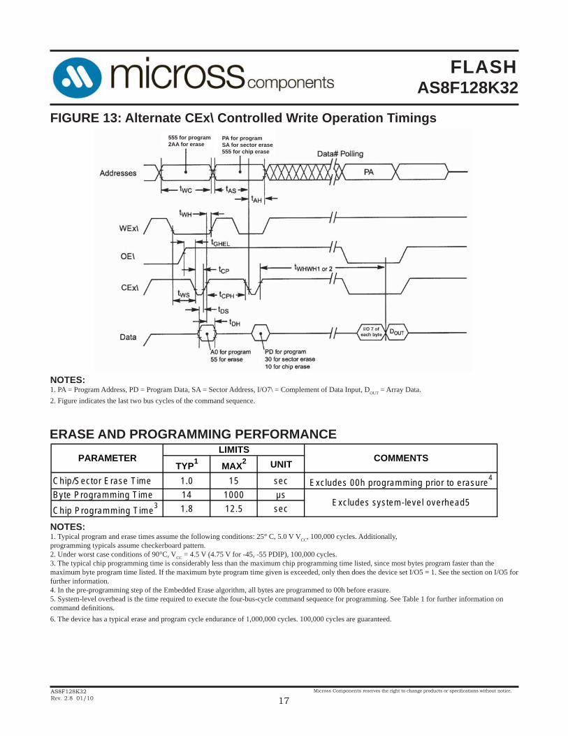
FIGURE 13: Alternate CEx\ Controlled Write Operation Timings
NOTES:1. PA = Program Address, PD = Program Data, SA = Sector Address, I/O7\ = Complement of Data Input, DOUT = Array Data.2. Figure indicates the last two bus cycles of the command sequence.
ERASE AND PROGRAMMING PERFORMANCE
TYP1
MAX2 UNIT
Chip/Sector Erase Time 1.0 15 sec Excludes 00h programming prior to erasure4
Byte Programming Time 14 1000 µs
Chip Programming Time3 1.8 12.5 sec
LIMITSCOMMENTSPARAMETER
Excludes system-level overhead5
NOTES:1. Typical program and erase times assume the following conditions: 25° C, 5.0 V VCC, 100,000 cycles. Additionally,programming typicals assume checkerboard pattern.2. Under worst case conditions of 90°C, VCC = 4.5 V (4.75 V for -45, -55 PDIP), 100,000 cycles.3. The typical chip programming time is considerably less than the maximum chip programming time listed, since most bytes program faster than the maximum byte program time listed. If the maximum byte program time given is exceeded, only then does the device set I/O5 = 1. See the section on I/O5 for further information.4. In the pre-programming step of the Embedded Erase algorithm, all bytes are programmed to 00h before erasure.5. System-level overhead is the time required to execute the four-bus-cycle command sequence for programming. See Table 1 for further information on command defi nitions.6. The device has a typical erase and program cycle endurance of 1,000,000 cycles. 100,000 cycles are guaranteed.
555 for program2AA for erase
PA for programSA for sector erase555 for chip erase

FLASHAS8F128K32
AS8F128K32Rev. 2.8 01/10
Micross Components reserves the right to change products or specifi cations without notice.
18
CAPACITANCEPARAMETER SYMBOL CONDITIONS MAX UNIT
A0 - A16 Capacitance CIN VIN = 0 50 pF
CSx\ & WEx\ Capacitance COUT VOUT = 0 20 pF
I/O0 - I/O31 Capacitance CIN2 VIN = 0 20 pF
NOTES:1. Sampled, not 100% tested.2. Test conditions TA = 25° C, f = 1.0 MHz.

FLASHAS8F128K32
AS8F128K32Rev. 2.8 01/10
Micross Components reserves the right to change products or specifi cations without notice.
19
MECHANICAL DEFINITIONS*
Micross Case #703 (Package Designator Q)SMD 5962-94716, Case Outlines M & N
*All measurements are in inches.
D2
D1
D
b
e
MIN MAXA 0.123 0.160A2 0.005 0.025b 0.013 0.017c 0.009 0.012DD1 0.870 0.890D2 0.980 1.000E 0.936 0.956eRL1 0.035 0.045
0.010 BSC
SYMBOLSMD SPECIFICATIONS, CASE N
0.800 BSC
0.050 BSC
DETAIL A
L1
1o - 7o
R
A A2
SEE DETAIL A
E
c
MIN MAXA 0.123 0.200A2 0.005 0.025b 0.013 0.017c 0.009 0.012DD1 0.870 0.890D2 0.980 1.000E 0.936 0.956eRL1 0.035 0.045
0.010 BSC
SYMBOLSMD SPECIFICATIONS, CASE M
0.800 BSC
0.050 BSC

FLASHAS8F128K32
AS8F128K32Rev. 2.8 01/10
Micross Components reserves the right to change products or specifi cations without notice.
20
MECHANICAL DEFINITIONS*
Micross Case (Package Designator Q1)SMD 5962-94716, Case Outline A
*All measurements are in inches.
MIN MAXA --- 0.200
A1 0.054 ---b 0.013 0.017Bc 0.009 0.012
D/E 0.980 1.000D1/E1 0.870 0.890D2/E2
eL 0.035 0.045R
SYMBOLSMD SPECIFICATIONS
0.010 TYP
0.010 TYP
0.800 BSC0.050 BSC

FLASHAS8F128K32
AS8F128K32Rev. 2.8 01/10
Micross Components reserves the right to change products or specifi cations without notice.
21
ORDERING INFORMATION
*AVAILABLE PROCESSESIT = Industrial Temperature Range -40oC to +85oCXT = Extended Temperature Range -55oC to +125oC883C = Full Military Processing -55oC to +125oC Q = Full QML Processing -55oC to +125oC
Device NumberPackage
TypeSpeed
nsProcess
AS8F128K32 Q -60 /*AS8F128K32 Q -70 /*AS8F128K32 Q -90 /*AS8F128K32 Q -120 /*AS8F128K32 Q -150 /*
Device NumberPackage
TypeSpeed
nsProcess
AS8F128K32 Q1 -60 /*AS8F128K32 Q1 -70 /*AS8F128K32 Q1 -90 /*AS8F128K32 Q1 -120 /*AS8F128K32 Q1 -150 /*
EXAMPLE: AS8F128K32Q-70/XT
EXAMPLE: AS8F128K32Q1-120/883C

FLASHAS8F128K32
AS8F128K32Rev. 2.8 01/10
Micross Components reserves the right to change products or specifi cations without notice.
22
MICROSS TO DSCC PART NUMBER* CROSS REFERENCE
Micross Package Designator Q
Micross Part # SMD Part # AS8F128K32Q-150/Q 5962-9471601HNX AS8F128K32Q-120/Q 5962-9471602HNX AS8F128K32Q-90/Q 5962-9471603HNX AS8F128K32Q-70/Q 5962-9471604HNX AS8F128K32Q-60/Q 5962-9471605HNX
AS8F128K32Q-150/Q 5962-9471601HMX AS8F128K32Q-120/Q 5962-9471602HMX AS8F128K32Q-90/Q 5962-9471603HMX AS8F128K32Q-70/Q 5962-9471604HMX AS8F128K32Q-60/Q 5962-9471605HMX
* Micross part number is for reference only. Orders received referencing the SMD part number will be processed per the SMD.
Micross Package Designator Q1
Micross Part # SMD Part # AS8F128K32Q1-150/Q 5962-9471601HAX AS8F128K32Q1-120/Q 5962-9471602HAX AS8F128K32Q1-90/Q 5962-9471603HAX AS8F128K32Q1-70/Q 5962-9471604HAX AS8F128K32Q1-60/Q 5962-9471605HAX