Flameproof Highproof High Range DP Switch FC series
4
FC HIGH PROOF HIGH RANGE PRESSURE DIFFERENCE SWITCHES Large Flamepa ths for better safety Seperate T erminal block for safe wiring Internal ground screw Robust Snap action microswitches for reliable switching Lock Screw for stable set-points Cover chained to main body Large Springs for finer set-points Nonme tallic diaphragms for minimal drift Large Sensing area for better sensitivity Approximate Weight : Pressure difference switches with Aluminium enclosure : 2.43 Kg. Pressure difference swi tches with Grey CI enclosure : 4.93 Kg. Pressure difference swi tches with SS enclosure : 5.13 Kg. Electrical Connection : Z 2 3 1 Some Applications : Appli cations requiring high static/system pressure but low pressure difference.
-
Upload
nk-instruments-pvt-ltd -
Category
Business
-
view
30 -
download
0
Transcript of Flameproof Highproof High Range DP Switch FC series
FC HIGH PROOF HIGH RANGE PRESSURE DIFFERENCE SWITCHES
Large Flamepaths for better safety
Seperate Terminal block for safe wiring
Internal ground screw Robust Snap action microswitches for reliable switching
Lock Screw for stable set-points
Cover chained to main body
Large Springs for finer set-points
Nonmetallic diaphragms for minimal drift
Large Sensing area for better sensitivity
Approximate Weight :
Pressure difference switches with Aluminium enclosure : 2.43 Kg. Pressure difference switches with Grey CI enclosure : 4.93 Kg. Pressure difference switches with SS enclosure : 5.13 Kg.
Electrical Connection :
Z 2 3
1 Some Applications :
Applications requiring high static/system pressure but low pressure difference.
HIGH PROOF HIGH RANGE PRESSURE DIFFERENCE SWITCHES FC
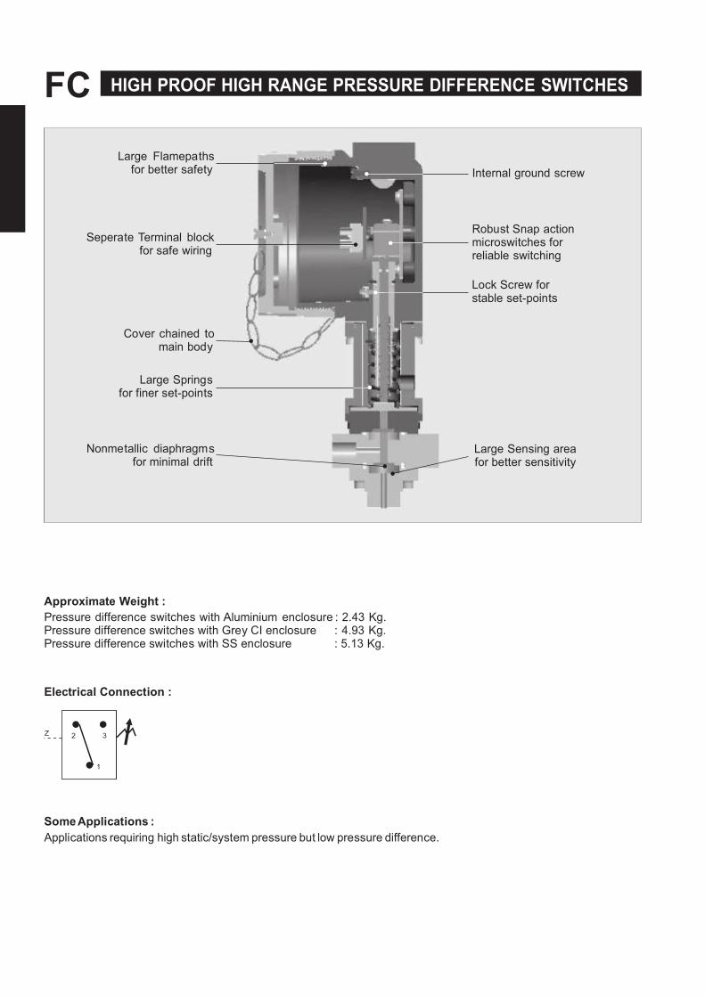
PRESSURE CAPSULE DETAILS
1 6
2 7
3 8
4
5 9
Note : wetted parts are mentioned in italics. 10
INSTALLATION DRAWING 145.0
110.0 (5.71)
(4.33) 126.0
26.0 (4.96) (1.02)
No. Description 1. Sealing Diaphragm (Teflon)
2. Sealing O Ring (Teflon) 3. Disc 4. Sealing O Ring
5. HP Plunger 6. LP Plunger
7. O Ring 8. Diaphragm 9. Csk. Screw (S.S.)
10. Pressure Housing
CABLE ENTRY
1/2" NPT(F) (Options Avail)
Ø7, MOUNTING HOLES
2 NOS
A/F 22
(A/F 0.86) LOW PRESSURE PORT
1/4" BSP(F)
HIGH PRESSURE PORT
1/4" BSP(F) APPROX. DIMENSIONS IN inches

NK Instruments Pvt. Ltd.B-501/504, 5th floor, Raunak Arcade, Near THC Hospital, Gokhale Road, Naupada,
Thane(W) 400602. Maharashtra INDIA Telefax Nos.: 91-22-25301330 / 31 / 32
E-Mail: [email protected] Web: http://www.nkinstruments.com
Skype: nitinkelkarskype Gtalk: nkinstruments2006
Authorised Dealer
FC HIGH PROOF HIGH RANGE PRESSURE DIFFERENCE SWITCHES
RANGE SELECTION TABLE
Range Code
Range bar (psi)
Differential* bar (psi)
Maximum Working Pressure
bar (psi)
Approximate Maximum for "A1"
microswitch
P01
0.1 - 1.0 (1.45 - 14.50)
0.24 (3.48)
200 (2900.76)
P02
0.1 - 1.5 (1.45 - 21.76)
0.40 (5.80)
200 (2900.76)
P03
0.2 - 2.6 (2.90 - 37.71)
0.40 (5.80)
200 (2900.76)
P04
0.2 - 3.6 (2.90 - 52.21)
0.60 (8.70)
200 (2900.76)
*Minimum differential increases with setpoint (Graphs available on request) * Note : Microswitches A2 through A9 can be supplied in some ranges and differentials will vary with microswitch used. Please contact sales office for details. Please check availability of adjustable differential with sales office.

NK Instruments Pvt. Ltd.B-501/504, 5th floor, Raunak Arcade, Near THC Hospital, Gokhale Road, Naupada,
Thane(W) 400602. Maharashtra INDIA Telefax Nos.: 91-22-25301330 / 31 / 32
E-Mail: [email protected] Web: http://www.nkinstruments.com
Skype: nitinkelkarskype Gtalk: nkinstruments2006
Authorised Dealer
HIGH PROOF HIGH RANGE PRESSURE DIFFERENCE SWITCHES FC
OW
TO
OE
FL
EP
OO
F
IG P
OO
F
IG
GE
PE
SS
E
IFF
EE
E S
WIT
ES
st
c
t
Gs
G
ss
fct
E
ty
Sz
S
tc T
y
vs
cs
tc
Ty
Go
up
Go
up
Go
up
Go
up
Go
up
Go
up
Go
up
Go
up
=
F =
F
f ss
stc
, A
TE
x &
IE
Ex
v,
t
A
s
IS
/IE
f
Gs
G. II
s f
st
t
s t
cv
ct
. W
v
y
fct
, y
ft t
f s
y t
s
t c
st.
P=
.
.
P=
.
.
P=
.
.
P=
.
.
Go
up
Go
up
Go
up
Go
up
Go
up
Go
up
Go
up
Go
up
. A
ff
stc
f
s
II
, t
½"
PT
c
ty
s
s
SP
T
ss
ffc
stc
, v
.
t
ss
,t
A.
cs
t,S
Sss
st
¼B
SP
tsz
&s
sc
fy
Ps
sc
fy f
t
v
ty. If
y t
fst
t
s
sc
f
,
ct
stc
s
t s
t
tt
tsc
ss
s.
F
P
A
S
F
t
tt
ts
s
f P
ss
s
ts
P
=
t
t
=
=
=
=
=
=
=
Pss
Pt
t /
Sz
S =
=
S
S /
¼"
BS
PF
S =
S
S /
¼
PT
F
Tf
= A
.
½"
PT
ts
= A
.
¾"
PT
ts
= A
.
x
.
ts
= G
y I
½
" P
T
ts
= G
y I
¾
" P
T
ts
= G
y I
x
.
t
s
= S
S
½"
PT
ts
= S
S
¾
" P
T
ts
= S
S
x
.
t
s
=
ss
ffc
stc
, fx
ff
t
tt sc
=
ss
ffc
stc
, fx
ff
t
t s
c
fx
fft
=
ss
ffc
stc
,
t s
c
s
Continuous efforts for product development may necessitate changes in these details without notice